WCDMA物理层协议TS25211-910
- 格式:doc
- 大小:5.25 MB
- 文档页数:58


1.1 小区选择和重选参数1.1.1 基本原理当UE开机后,则首先执行PLMN选择,然后执行小区选择过程。
当选择到合适的小区后,则选择该小区驻留,并向网络侧发起注册等过程。
当驻留到某个服务小区后,随着UE的移动,信道质量的变化,UE将会进行小区重选过程。
(1)PLMN的选择过程PLMN选择的标准是CPICH RSCP值大于或等于-95dBm,UE将读取其搜索到最强信号的小区的PLMN。
如果不满足上述的标准,但能够解出PLMN的标识,则也认为该PLMN是可作为选择接入的PLMN。
(2)小区选择过程选择一个信号最强的小区作为初始接入的小区。
小区选择标准S规则定义如下:其中:(3)小区重选择过程当UE驻留到小区后,则会执行小区重选过程:小区重选包括UE对测量的执行和测量的判决两部分。
下面仅针对小区不属于HCS小区的情况作介绍。
(1)测量规则:在下面的规则中,UE用Squal(FDD 小区)作为Sx :1若Sx > S intrasearch,则UE不需要执行频内测量;若Sx <= S intrasearch,则UE将执行频内测量;若S intrasearch, 未配置,则UE一直进行频内测量;2若Sx > S intersearch,则UE不需进行频间测量;若Sx <= S intersearch,则UE将执行频间测量;若S intersearch未配置,则UE一直进行频间测量;3若Sx > Ssearch RAT m, 则UE不需在不同无线测量技术之间的小区上进行测量;若Sx <= Ssearch RATm, 则UE将对其他RAT m 小区进行测量;若Ssearch RAT m, 未配置,则UE一直对其他RAT m小区进行测量。
(2)小区重选的判决规则:以下小区重选标准用于频内小区,频间小区和inter-RAT 小区:小区排队标准R规则为:其中:其中:Tn是一个定时器,当相邻小区的信号质量比服务小区的信号质量加一个服务小区和该相邻小区的相对偏差(Qoffset1s,n 或者Qoffset2s,n)还要高时,则启动该定时器。
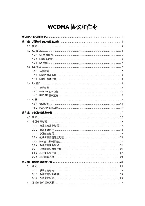
WCDMA协议和信令WCDMA协议和信令 (1)第1章UTRAN接口协议和功能 (4)1.1 概述 (4)1.2 Uu接口 (5)1.2.1 Uu协议结构 (5)1.2.2 RRC层功能 (6)1.2.3 L1功能 (7)1.3 Iub接口 (7)1.3.1 协议结构 (7)1.3.2 NBAP基本功能 (9)1.3.3 NBAP基本过程 (9)1.4 Iur接口 (10)1.4.1 协议结构 (10)1.4.2 RNSAP基本功能 (11)1.4.3 RNSAP基本过程 (12)1.5 Iu接口 (14)1.5.1 协议结构 (14)1.5.2 RANAP基本功能 (17)第2章小区相关流程分析 (17)2.1 概念 (17)2.2 小区相关过程 (18)2.2.1 资源状态指示过程 (18)2.2.2 资源审计过程 (18)2.2.3 小区建立过程 (19)2.2.4 公共传输信道建立过程 (20)2.2.5 Iub接口用户面建立 (21)2.2.6 系统信息更新过程 (21)2.2.7 公共测量初始化过程 (21)2.2.8 小区重配置过程 (22)2.2.9 小区删除过程 (23)第3章系统信息流程分析 (28)3.1 概述 (28)3.1.1 系统信息结构 (28)3.1.2 系统信息监听机制 (29)3.1.3 系统信息功能 (29)3.2 系统信息广播和更新 (30)3.2.2 系统信息更新 (31)第4章呼叫建立和释放流程分析 (31)4.1 概述 (31)4.2 寻呼流程 (32)4.2.1 概述 (32)4.2.2 寻呼空闲模式或PCH状态的UE (32)4.2.3 寻呼CELL_DCH或CELL_FACH状态的UE (33)4.3 RRC连接建立流程 (34)4.3.1 概述 (34)4.3.2 在专用信道上建立RRC连接 (34)4.3.3 在公用信道上建立RRC连接 (35)4.3.4 RRC连接拒绝 (36)4.4 直传消息流程 (36)4.4.1 概述 (36)4.4.2 初始直传 (36)4.4.3 上行直传 (37)4.4.4 下行直传 (38)4.5 UE能力信息流程 (39)4.5.1 UE能力信息查询 (39)4.5.2 UE能力信息更新 (40)4.6 RAB建立流程 (40)4.6.1 概述 (40)4.6.2 DCH-DCH (41)4.6.3 CCH-DCH (44)4.6.4 CCH-CCH (45)4.7 业务释放流程 (45)4.7.1 概述 (45)4.7.2 Iu信令连接释放流程 (46)4.7.3 RAB释放流程 (47)4.7.4 CS域Iu信令连接和RAB的联合释放流程 (49)4.7.5 RRC连接释放流程 (50)第6章移动性管理流程分析 (53)6.1 概述 (53)6.2 前向切换流程 (53)6.2.1 概述 (53)6.2.2 小区更新 (53)6.2.3 URA更新 (55)6.3 软切换流程 (56)6.3.1 概述 (56)6.3.2 无线链路增加 (57)6.3.4 无线链路替换 (59)6.3.5 RADIO LINK SETUP REQUEST消息 (60)6.3.6 ACTIVE SET UPDATE消息 (61)6.4 硬切换流程 (62)6.4.1 概述 (62)6.4.2 压缩模式 (63)6.4.3 Iur接口硬切换 (64)6.4.4 联合硬切换 (64)6.4.5 RADIO LINK SETUP REQUEST消息 (66)6.4.6 PHYSICAL CHANNEL RECONFIGURATION消息 (66)6.5 系统间切换流程 (69)6.5.1 概述 (69)6.5.2 WCDMA—>GSM系统间切换 (70)6.5.3 GSM—>WCDMA系统间切换 (72)6.5.4 GSM/GPRS—>WCDMA小区重选 (74)6.5.5 WCDMA—>GSM/GPRS小区重选 (74)6.5.6 HANDOVER FROM UTRAN COMMAND消息 (76)6.5.7 HANDOVER TO UTRAN COMMAND消息 (77)6.6 迁移流程 (79)6.6.1 概述 (79)6.6.2 静态迁移 (79)6.6.3 硬切换伴随迁移 (83)6.6.4 前向切换伴随迁移 (85)附录A 一次呼叫典型流程 (87)B.1 概述 (87)B.2 主叫流程 (87)B.3 被叫流程 (90)附录C 缩略语 (93)第1章UTRAN接口协议和功能1.1 概述图1-1 UTRAN接口如图1-1所示,UMTS系统中UTRAN接口包括Iub/Iur/Iu/Uu接口,接口连接的网元如表1-1所示:表1-1 UTRAN接口Iub/Iur/Iu/Uu都为标准的接口,可以连接不同设备供应商提供的设备。
![3gppts25[1].212中文规范(无线接口物理层技术规范:复用与信道编码)](https://uimg.taocdn.com/35556ad280eb6294dd886c4d.webp)
通信标准参考性技术文件IMT-DS FDD(WCDMA)系统无线接口物理层技术规范:复用与信道编码IMT-DS FDD(WCDMA) System Radio Interface Physical Layer Techinical Specification: Multiplexing and channel coding20XX-XX-XX发布 20XX-XX-XX实施中华人民共和国信息产业部科学技术司印发目次1 范围 (2)2 引用标准 (2)3名词与缩略语 (2)3.1 定义 (2)3.2 符号 (2)3.3 缩略语 (3)4. 复用、信道编码和交织 (4)4.1 概述 (4)4.2 传输信道编码/复用 (4)4.2.1 CRC附加 (8)4.2.2 传输块的级联和码块分段 (9)4.2.3 信道编码 (10)4.2.4 无线帧尺寸均衡 (17)4.2.5 第一次交织 (18)4.2.6 无线帧分段 (20)4.2.7 速率匹配 (21)4.2.8 传输信道(TRCH)复用 (41)4.2.9 不连续发射(DTX)比特的插入 (42)4.2.10 物理信道的分段 (43)4.2.11 第二次交织 (44)4.2.12 物理信道的映射 (45)4.2.13 对不同编码组合传输信道(CCTRCH)类型的限制 (46)4.2.14 不同传输信道到一个编码组合传输信道(CCTRCH)的复用以及一个编码组合传输信道(CCTRCH)到物理信道的映射 (47)4.3 传输格式检测 (49)4.3.1 盲传输格式检测 (49)4.3.2 基于传输格式组合标识(TFCI)的明确传输格式检测 (50)4.3.3 传输格式合并标志(TFCI)的编码 (50)4.3.4 在分裂模式中的传输格式组合标识(TFCI)的操作 (51)4.3.5 传输格式组合标识(TFCI)码字的映射 (53)4.4 压缩模式 (54)4.4.1 上行链路的帧结构 (54)4.4.2 下行链路帧结构的类型 (54)4.4.3减少传输时间的方法 (55)4.4.4 传输间隔位置 (55)附录A (信息): 盲传输检测 (57)A.1使用固定位置的盲传输格式检测 (57)A.1.1 使用接收功率比的盲传输格式检测 (57)A.1.2 使用CRC的盲传输格式检测 (58)附录B (信息): 压缩模式的等待时间 (61)B.1DL, UL 与DL+UL压缩模式的等待时间 (61)前言本通信标准参考性技术文件主要用于描述IMT-DS FDD(WCDMA)系统的无线接口的物理层的编码与复用部分内容。
WCDMA移动通信系统基本知识介绍技术研发部毕猛内容提要1. WCDMA导论2. 物理层3. 移动性管理4.无线资源管理Section 1 W-CDMA 导论主要内容多址接入及双工技术WCDMA新特点WCDMA与GSM的主要区别业务分类UMTS系统结构DS-CDMA码字Rake接收机发射分集频率时间功率频率时间功率频率时间功率FDMA TDMACDMA 通信系统中有三种多址接入技术:•频分多址Fre •时分多址Fre+Ts •码分多址Fre+Code多址接入双工间隔:190MHzFDD时间频率功率5 MHz5 MHz码复用& 频分双工ULDLUMTS 用户1UMTS 用户2时间频率功率TDD5 MHzDL UL DL码复用&时分双工DL 666.67 μsULUMTS 用户2UMTS 用户1W-CDMA: FDD or TDD双工技术WCDMA的新特点 WCDMA的新特点9提供高速的数据速率,最高可达到2Mbps,将来如果采用HSDPA将提高到8~10Mbps(甚至到20Mbps,如果采用MIMO天线技术。
9可变比特速率。
(可变扩频因子9采用异步方式,无需GPS精确定时,方便室内规划。
9支持上、下行不对称的业务,如视频点播和网页浏览,下行业务远大于上行业务。
9更高的频谱利用率,频率复用度为1。
91500Hz的快速功率控制,更好地克服快衰落的影响。
0.5、1、1.5、2 dB (可变功率控制步长1500Hz功率控制频率软切换,更软切换,硬切换切换666.7us时隙长10ms (包含15个时隙帧长2Mbps (for Release99&Release4最大业务速率 3.84Mcps码片速率上行BPSK ,下行QPSK 调制方式分组和电路交换数据类型Node B :-121dBm ,MS :-117dBm (BER 为10-3接收机灵敏度Rake 接收机接收机异步方式同步方式卷积编码,Turbo 编码(对高速业务信道编码8种速率的AMR 编码(4.75~12.2kbps语音编码 4.4~5.2MHz载波间隔1频率复用度2×5MHz 最小频率需求上行:1920~1980MHz,下行:2110~2170MHz 规划频段频率栅格与定标频率WCDMA 的主要参数语音和低速数据业务(理论最大171.2kbps ,实际几十kbpsAMR 语音(4.75~12.2kbps、CS64kbps 、最大2Mbps 的分组数据业务。
中国联通公司企业标准QB/CU 中国联通WCDMA无线参数规范(V1.0)20**-**-**发布20**-**-**实施编制历史目录前言 (4)1概述 (5)1.1内容介绍 (5)1.2阶段关注 (5)1.3注意事项 (6)1.4版本说明 (6)2功率分配参数 (7)2.1公共信道功率分配 (7)2.2专用信道功率分配 (8)3小区选择和重选参数 (8)3.1同频小区重选 (8)3.2异频小区重选 (9)3.3异系统小区重选 (10)3.3.1WCDMA 至GSM 小区重选 (10)3.3.2GSM 至 WCDMA 小区重选 (11)4接入、寻呼和连接状态参数 (11)4.1空闲态接入参数 (11)4.2空闲态寻呼参数 (13)4.3连接态参数 (14)5功率控制参数 (15)5.1上行功控参数 (16)5.2下行功控参数 (18)6切换控制参数 (19)6.1频内切换参数 (20)6.2频间切换参数 (21)6.3异系统切换参数 (23)7压模参数 (25)7.1准入和负载控制参数 (26)7.2准入控制华为系统: (27)7.3负载控制华为系统: (28)8状态转换参数 (29)9HSPA参数 (31)9.1HSDPA参数 (31)9.2HSUPA参数 (35)10附录: (38)前言本文目的是为规范广东联通WCDMA无线网络性能参数在日常优化工作中优化方向和为各地市分公司从事无线网络优化的工程师了解WCDMA无线参数提供参考。
现规范文档为第一版本,以后会根据网络版本和对网络的认识加深继续完善。
同时,希望得到各位同事的反馈意见,以便改进和修正,谢谢!本规程由中国联合网络通信集团有限公司广东分公司提出并归口本规程起草单位:中国联合网络通信集团有限公司广东分公司本规程最终解释权归中国联合网络通信集团有限公司广东分公司1概述1.1内容介绍本规范文档从WCDMA系统的众多的无线参数中归纳总结一些常用参数,作为WCDMA网规网优人员的参数配置指导书,总结了WCDMA RAN侧的各个系统参数的参数名称、物理意义、设置范围、缺省配置、对系统性能的影响以及它们在特定场景的应用(部分)等。
wcdma终端物理层设计方案全文共四篇示例,供读者参考第一篇示例:WCDMA(Wideband Code Division Multiple Access)是一种第三代移动通信技术,它采用了CDMA技术和宽带信道的组合,可以提供更高的数据传输速率和更好的网络容量。
WCDMA终端物理层设计方案,即终端设备的硬件和软件设计方案,是整个系统中至关重要的一环。
本文将详细介绍WCDMA终端物理层设计方案的关键技术和设计要点。
一、物理层接口在WCDMA系统中,终端设备与基站之间通过物理层接口进行通信。
物理层接口的设计包括传输信道、扰码、调制等技术。
WCDMA 系统中采用了直序扩频技术,通过使用高速码片序列将用户数据进行扩展,使得用户数据传输更加安全可靠。
WCDMA系统中还采用了正交频分多址(OFDM)调制技术,可以在相同带宽下实现更高的数据传输速率和更好的抗干扰性能。
二、天线设计WCDMA终端设备的天线设计对信号接收和发送效果至关重要。
天线设计需要考虑天线增益、辐射模式、频率范围等因素。
为了提高信号接收效果,需要采用多种天线技术,如多天线通信技术、智能天线技术等。
通过合理设计天线参数和优化天线布局,可以有效提高终端设备的信号接收和发送性能。
三、功率控制在WCDMA系统中,功率控制是终端设备与基站之间进行通信的关键技术之一。
功率控制需要根据信道质量和信噪比等因素实时调整终端设备的发射功率,以确保数据传输的可靠性和稳定性。
为了降低电池功耗和减少电磁辐射,需要使用功率控制技术对终端设备的功率进行有效管理。
四、频谱分配在WCDMA系统中,频谱资源是有限的,因此需要合理进行频谱分配,以确保各个终端设备之间的通信不受干扰。
频谱分配需要考虑用户数量、数据传输速率、业务类型等因素,通过动态频谱分配技术可以提高频谱利用率和系统容量。
五、功耗管理WCDMA终端设备的功耗管理是整个系统设计中的一个重要方面。
功耗管理需要根据终端设备的工作状态和用户需求合理调整各个子系统的功耗,以延长终端设备的待机时间和工作时间。


通信标准参考性技术文件IMT-DS FDD(WCDMA)系统无线接口物理层技术规范:物理层过程IMT-DS FDD(WCDMA) System Radio Inerface Physical Layer Technical Specification: Physical Layer Procedure20XX-XX-XX发布 20XX-XX-XX实施中华人民共和国信息产业部科学技术司印发目次1 范围 (1)2 引用标准 (1)3 定义和缩略语 (1)4 同步过程 (2)4.1 小区搜索 (2)4.2 公共物理信道同步 (2)4.3 DPCCH/DPDCH同步 (2)4.3.1 同步原语 (2)4.3.2 无线链路建立 (3)4.3.3 无线链路监测 (4)4.3.4 传输定时的调整 (5)5 功率控制 (5)5.1 上行功率控制 (5)5.1.1 PRA CH (5)5.1.2 DPCCH/DPDCH (5)5.1.3 PCPCH (13)5.2 下行功率控制 (15)5.2.1 DPCCH/DPDCH (15)5.2.2 PDSCH (20)5.2.3 AICH 205.2.4 PICH 205.2.5 S-CCPCH (20)5.2.6 CSICH (20)6 随机接入过程 (20)6.1 物理随机接入过程 (20)6.1.1 RACH子信道 (22)6.1.2 RACH接入时隙集合 (22)6.2 CPCH接入过程 (23)7 闭环模式发射分集 (26)7.1 反馈信息的确定 (27)7.2 闭环模式1 (28)7.2.1 模式1帧尾调整 (29)7.2.2 模式1的正常初始化 (29)7.2.3 压缩模式下模式1的操作 (30)7.3 闭环模式2 (31)7.3.1 模式2的帧尾调整 (32)7.3.2 模式2的初始化 (32)7.3.3 压缩模式下模式2的操作过程 (33)8 IPDL定位方法的空闲周期 (34)8.1 概述 (34)8.2 IPDL的参数 (34)8.3 空闲周期位置的计算 (34)附录A(信息):天线验证 (35)附录B(信息):功率控制 (36)B.1 功率控制定时 (36)B.2 UE实现的例子 (37)B.3 调整环路 (37)附录C(信息):小区搜索过程 (38)前言本通信参考性技术文件主要定义了IMT-2000 DS系统FDD模式(WCDMA)的Uu接口的内容,主要对Uu接口技术规范中的信令传输部分进行规定和说明。
第8章【网络通信】华为培训第8章WCDMA网管系统8.1 概述WCDMA网管建设思路要紧根据TMN管理框架搭建,后续引入了TMF组织提出的TOM理论。
3G网络管理的建立很大程度参考了3GPP 32系列协议,下列是一些与网管有关的常用协议:32101-311协议:要紧描述3G电信管理的基本原理与需求;32102-311协议:要紧描述3G管理框架;32104-311协议:要紧描述3G性能管理;32105-001协议:要紧描述3G计费;32106-301协议:要紧描述3G配置管理;32111-301协议:要紧描述3G故障管理;33102-340协议:要紧描述3G安全管理:安全框架;33103-320协议:要紧描述3G安全管理:安全导引;按照TMN管理框架,WCDMA系统网络管理分为网元管理层、网络管理层、业务管理层与商务管理层。
网管今后的进展趋势是趋近于一个多管理层综合考虑的解决方案,而且管理侧重网络管理、业务管理与企业管理。
不管是综合考虑还是分管理层考虑网管的解决方案,首先要研究清晰的都是各管理层的管理功能、信息模型与上下互通接口的标准化,并逐步将研究中心向上层移动。
研究中心的上移,会影响研究方式的改变。
TMN管理框架通常使用从下向上的设计思想,因此TMN在网元管理层与网络管理层有一套非常稳固的规范。
在高层管理层中网管系统为运营商与最终用户提供客户化的管理,网络管理不再是简单的网络设备操作保护,广义上还要包含在新的商业模式下的网络优化规划决策管理、业务服务支撑管理、客户服务中心与客户关系管理。
本文简单介绍了TMN网管体系基本知识与TOM的基本理论思路,并对3G网管的要紧业务功能进行简单介绍;因在3G网络建设初期,关于网元设备的管理与组网模型更加重要,本文介绍了关于设备管理层面的网管建设思路。
8.2 网管基础知识8.2.1 TMN基本知识介绍1. TMN的基本概念TMN即Telecommunication Manager Network,电信管理网的缩写。
WP112010WCDMA无线网络覆盖规划ISSUE1.01WCDMA无线网络覆盖规划x-1WCDMA无线网络覆盖规划/doc/8faef402bed5b9f3f90f1cb3.html Copyright ? 2008 Huawei Technologies Co., Ltd. All rights reserved.华为技术有限公司版权所有未经许可不得扩散WCDMA无线网络覆盖规划x-2培训目标学完本课程后,您应该能:了解网络规划的内容和流程掌握上行链路预算及其包含元素的含义掌握下行链路预算及其包含元素的含义Copyright ? 2008 Huawei Technologies Co., Ltd. All rights reserved.Page 2华为技术有限公司版权所有未经许可不得扩散WCDMA无线网络覆盖规划x-3目录1. WCDMA网络规划流程2. R99覆盖规划3. HSDPA覆盖规划Copyright ? 2008 Huawei Technologies Co., Ltd. All rights reserved.Page 3华为技术有限公司版权所有未经许可不得扩散WCDMA无线网络覆盖规划x-4容量-覆盖-质量WCDMA 系统的容量、覆盖、质量关系WCDMA 系统是自干扰系统,容量、覆盖、质量之间密切相关容量-覆盖(小区呼吸)设计负载增加,容量增大,干扰增加,覆盖减小容量容量-质量(通过外环功控提高目标SNR)通过降低部分连接的质量要求,可以提高系统容量质量覆盖覆盖-质量(AMRC)通过降低部分连接的质量要求,同样可以增加覆盖能力Copyright ? 2008 Huawei Technologies Co., Ltd. All rights reserved.Page 4对于WCDMA网络运营商来说,如何经济有效地建设一个WCDMA网络,保证网络建设的性价比是运营商所关心的问题。
通信标准参考性技术文件IMT-DS FDD(WCDMA)系统无线接口物理层技术规范:物理层测量IMT-DS FDD(WCDMA) System Radio Interface Physical Layer Technical Specification: Physical LayerMeasurement20XX-XX-XX发布 20XX-XX-XX实施中华人民共和国信息产业部科学技术司印发目次前言 (III)1 范围 (2)2 引用标准 (2)3 缩写 (3)4 UE/UTRAN 测量的控制 (3)5 UTRA FDD需要的测量能力 (3)5.1 UE的测量能力 (4)5.1.1 CPICH RSCP (4)5.1.2 PCCPCH RSCP (4)5.1.3 SIR (4)5.1.4 UTRA 载波RSSI (4)5.1.5 GSM 载波RSSI (5)5.1.6 CPICH Ec/No (5)5.1.7 传输信道的BLER (5)5.1.8 UE 发射功率 (5)5.1.9 SFN-CFN 观测时间差 (5)5.1.10 SFN-SFN 观测时间差 (6)5.1.11 UE Rx-Tx 时间差 (6)5.1.12 相对GSM小区的观测时间差 (6)5.1.13 用于定位业务的UE GPS小区帧时序 (6)5.2 UTRAN的测量能力 (7)5.2.1 RSSI (7)5.2.2 SIR (7)5.2.3 SIR error (7)5.2.4 发射的载波功率 (7)5.2.5 发射的码功率 (7)5.2.6 传输信道的BER (8)5.2.7 物理信道的BER (8)5.2.8 往返时间 (8)5.2.9 用于定位业务的UTRAN GPS 小区帧的时序 (8)5.2.10 PRACH/PCPCH 传播延时 (9)5.2.11 确认的PRACH前导 (9)5.2.12 PCPCH的检测接入前导 (9)5.2.13 确认的PCPCH接入前导 (10)6 UTRA FDD 的测量 (10)6.1 UE测量 (10)6.1.1 压缩模式 (10)前言本通信参考性技术文件包括了为了支持在空闲模式和连接模式的操作,UE和网络在FDD模式下完成的测量的描述和定义。
3GPP TS 25.211 V9.1.0 (2009-12)Technical Specification3rd Generation Partnership Project;Technical Specification Group Radio Access Network;Physical channels and mapping of transport channelsonto physical channels (FDD)(Release 9)The present document has been developed within the 3rd Generation Partnership Project (3GPP TM) and may be further elaborated for the purposes of 3GPP. The present document has not been subject to any approval process by the 3GPP Organisational Partners and shall not be implemented.This Specification is provided for future development work within 3GPP only. The Organisational Partners accept no liability for any use of this Specification. Specifications and reports for implementation of the 3GPP TM system should be obtained via the 3GPP Organisational Partners' Publications Offices.KeywordsUMTS, radio, layer 13GPPPostal address3GPP support office address650 Route des Lucioles - Sophia AntipolisValbonne - FRANCETel.: +33 4 92 94 42 00 Fax: +33 4 93 65 47 16InternetCopyright NotificationNo part may be reproduced except as authorized by written permission.The copyright and the foregoing restriction extend to reproduction in all media.© 2009, 3GPP Organizational Partners (ARIB, ATIS, CCSA, ETSI, TTA, TTC).All rights reserved.UMTS™ is a Trade Mark of ETSI registered for the benefit of its members3GPP™ is a Trade Mark of ETSI registered for the benefit of its Members and of the 3GPP Organizational PartnersLTE™ is a Trade Mark of ETSI currently being registered for the benefit of i ts Members and of the 3GPP Organizational Partners GSM® and the GSM logo are registered and owned by the GSM AssociationContentsForeword (5)1Scope (6)2References (6)3Symbols, abbreviations and definitions (7)3.1Symbols (7)3.2Abbreviations (7)3.3Definitions (8)4Services offered to higher layers (8)4.1Transport channels (8)4.1.1Dedicated transport channels (8)4.1.1.1DCH - Dedicated Channel (8)4.1.1.2E-DCH – Enhanced Dedicated Channel (8)4.1.2Common transport channels (8)4.1.2.1BCH - Broadcast Channel (8)4.1.2.2FACH - Forward Access Channel (8)4.1.2.3PCH - Paging Channel (9)4.1.2.4RACH - Random Access Channel (9)4.1.2.5Void (9)4.1.2.6Void (9)4.1.2.7HS-DSCH – High Speed Downlink Shared Channel (9)4.1.2.7A E-DCH - Enhanced Dedicated Channel (9)4.2Indicators (9)5Physical channels and physical signals (9)5.1Physical signals (10)5.2Uplink physical channels (10)5.2.1Dedicated uplink physical channels (10)5.2.1.1DPCCH and DPDCH (10)5.2.1.2HS-DPCCH (13)5.2.1.3E-DPCCH and E-DPDCH (13)5.2.2Common uplink physical channels (15)5.2.2.1Physical Random Access Channel (PRACH) (15)5.2.2.1.1Overall structure of random-access transmission (15)5.2.2.1.2RACH preamble part (16)5.2.2.1.3RACH message part (16)5.2.2.2Void (17)5.3Downlink physical channels (17)5.3.1Downlink transmit diversity (17)5.3.1.1Open loop transmit diversity (19)5.3.1.1.1Space time block coding based transmit antenna diversity (STTD) (19)5.3.1.1.2Time Switched Transmit Diversity for SCH (TSTD) (21)5.3.1.2Closed loop transmit diversity (21)5.3.2Dedicated downlink physical channels (21)5.3.2.1STTD for DPCH and F-DPCH (25)5.3.2.2Dedicated channel pilots with closed loop mode transmit diversity (26)5.3.2.3Void (27)5.3.2.4E-DCH Relative Grant Channel (27)5.3.2.5E-DCH Hybrid ARQ Indicator Channel (29)5.3.2.6Fractional Dedicated Physical Channel (F-DPCH) (29)5.3.3Common downlink physical channels (30)5.3.3.1Common Pilot Channel (CPICH) (30)5.3.3.1.1Primary Common Pilot Channel (P-CPICH) (31)5.3.3.1.2Secondary Common Pilot Channel (S-CPICH) (31)5.3.3.2Downlink phase reference (32)5.3.3.3Primary Common Control Physical Channel (P-CCPCH) (33)5.3.3.3.1Primary CCPCH structure with STTD encoding (34)5.3.3.4Secondary Common Control Physical Channel (S-CCPCH) (34)5.3.3.4.1Secondary CCPCH structure with STTD encoding (37)5.3.3.5Synchronisation Channel (SCH) (37)5.3.3.5.1SCH transmitted by TSTD (38)5.3.3.6Void (38)5.3.3.7Acquisition Indicator Channel (AICH) (38)5.3.3.8Void (42)5.3.3.9Void (42)5.3.3.10Paging Indicator Channel (PICH) (42)5.3.3.11Void (43)5.3.3.12Shared Control Channel (HS-SCCH) (43)5.3.3.13High Speed Physical Downlink Shared Channel (HS-PDSCH) (43)5.3.3.14E–DCH Absolute Grant Channel (E-AGCH) (44)5.3.3.15MBMS Indicator Channel (MICH) (44)6Mapping and association of physical channels (45)6.1Mapping of transport channels onto physical channels (45)6.2Association of physical channels and physical signals (46)7Timing relationship between physical channels (47)7.1General (47)7.2PICH/S-CCPCH timing relation (48)7.2A PICH/HS-SCCH timing relation (48)7.3PRACH/AICH timing relation (49)7.3A UL/DL timing relation for Enhanced Uplink in CELL_FACH state and IDLE mode (50)7.4Void (51)7.5Void (51)7.6DPCCH/DPDCH timing relations (51)7.6.1Uplink (51)7.6.2Downlink (51)7.6.3Uplink/downlink timing at UE (51)7.7Uplink DPCCH/HS-DPCCH/HS-PDSCH timing at the UE (51)7.8HS-SCCH/HS-PDSCH timing (52)7.9MICH/S-CCPCH timing relation (52)7.10E-HICH/P-CCPCH/DPCH timing relation (53)7.11E-RGCH/P-CCPCH/DPCH timing relation (53)7.12E-AGCH/P-CCPCH timing relation (54)7.13E-DPDCH/E-DPCCH/DPCCH timing relation (54)Annex A (informative): Change history (55)ForewordThis Technical Specification (TS) has been produced by the 3rd Generation Partnership Project (3GPP).The contents of the present document are subject to continuing work within the TSG and may change following formal TSG approval. Should the TSG modify the contents of the present document, it will be re-released by the TSG with an identifying change of release date and an increase in version number as follows:Version x.y.zwhere:x the first digit:1 presented to TSG for information;2 presented to TSG for approval;3 or greater indicates TSG approved document under change control.y the second digit is incremented for all changes of substance, i.e. technical enhancements, corrections, updates, etc.z the third digit is incremented when editorial only changes have been incorporated in the document.1 ScopeThe present document describes the characteristics of the Layer 1 transport channels and physicals channels in the FDD mode of UTRA. The main objectives of the document are to be a part of the full description of the UTRA Layer 1, and to serve as a basis for the drafting of the actual technical specification (TS).2 ReferencesThe following documents contain provisions which, through reference in this text, constitute provisions of the present document.∙References are either specific (identified by date of publication, edition number, version number, etc.) or non-specific.∙For a specific reference, subsequent revisions do not apply.∙For a non-specific reference, the latest version applies. In the case of a reference to a 3GPP document (including a GSM document), a non-specific reference implicitly refers to the latest version of that document in the same Release as the present document.[1] 3GPP TS 25.201: "Physical layer - general description".[2] 3GPP TS 25.211: "Physical channels and mapping of transport channels onto physical channels(FDD)".[3] 3GPP TS 25.212: "Multiplexing and channel coding (FDD)".[4] 3GPP TS 25.213: "Spreading and modulation (FDD)".[5] 3GPP TS 25.214: "Physical layer procedures (FDD)".[6] 3GPP TS 25.221: "Transport channels and physical channels (TDD)".[7] 3GPP TS 25.222: "Multiplexing and channel coding (TDD)".[8] 3GPP TS 25.223: "Spreading and modulation (TDD)".[9] 3GPP TS 25.224: "Physical layer procedures (TDD)".[10] 3GPP TS 25.215: "Physical layer - Measurements (FDD)".[11] 3GPP TS 25.301: "Radio Interface Protocol Architecture".[12] 3GPP TS 25.302: "Services Provided by the Physical Layer".[13] 3GPP TS 25.401: "UTRAN Overall Description".[14] 3GPP TS 25.133: "Requirements for Support of Radio Resource Management (FDD)".[15] 3G TS 25.427: "UTRAN Overall Description :UTRA Iub/Iur Interface User Plane Protocol forDCH data streams".[16] 3GPP TS 25.435: "UTRAN Iub Interface User Plane Protocols for Common Transport ChannelData Streams".3 Symbols, abbreviations and definitions3.1 SymbolsN data1The number of data bits per downlink slot in Data1 field.N data2The number of data bits per downlink slot in Data2 field. If the slot format does not contain a Data2 field, N data2 = 0.3.2 AbbreviationsFor the purposes of the present document, the following abbreviations apply:16QAM 16 Quadrature Amplitude Modulation4PAM 4 Pulse-Amplitude Modulation64QAM 64 Quadrature Amplitude ModulationAI Acquisition IndicatorAICH Acquisition Indicator ChannelBCH Broadcast ChannelCCPCH Common Control Physical ChannelCCTrCH Coded Composite Transport ChannelCPICH Common Pilot ChannelCQI Channel Quality IndicatorDCH Dedicated ChannelDPCCH Dedicated Physical Control ChannelDPCH Dedicated Physical ChannelDPDCH Dedicated Physical Data ChannelDTX Discontinuous TransmissionE-AGCH E-DCH Absolute Grant ChannelE-DCH Enhanced Dedicated ChannelE-DPCCH E-DCH Dedicated Physical Control ChannelE-DPDCH E-DCH Dedicated Physical Data ChannelE-HICH E-DCH Hybrid ARQ Indicator ChannelE-RGCH E-DCH Relative Grant ChannelFACH Forward Access ChannelFBI Feedback InformationF-DPCH Fractional Dedicated Physical ChannelFSW Frame Synchronization WordHS-DPCCH Dedicated Physical Control Channel (uplink) for HS-DSCHHS-DSCH High Speed Downlink Shared ChannelHS-PDSCH High Speed Physical Downlink Shared ChannelHS-SCCH Shared Control Channel for HS-DSCHICH Indicator ChannelMBSFN MBMS over a Single Frequency NetworkMICH MBMS Indicator ChannelMIMO Multiple Input Multiple OutputMUI Mobile User IdentifierNI MBMS Notification IndicatorPCH Paging ChannelP-CCPCH Primary Common Control Physical ChannelPICH Page Indicator ChannelPRACH Physical Random Access ChannelPSC Primary Synchronisation CodeRACH Random Access ChannelRNC Radio Network ControllerS-CCPCH Secondary Common Control Physical ChannelSCH Synchronisation ChannelSF Spreading FactorSFN System Frame NumberSSC Secondary Synchronisation CodeSTTD Space Time Transmit DiversityTFCI Transport Format Combination IndicatorTSTD Time Switched Transmit DiversityTPC Transmit Power ControlUE User EquipmentUTRAN UMTS Terrestrial Radio Access Network3.3 DefinitionsHS-DSCH cell set: A set of cells that can be configured together as the serving and secondary serving HS-DSCH cells for a UE. This term is applicable also to non-serving cells in an active set.4 Services offered to higher layers4.1 Transport channelsTransport channels are services offered by Layer 1 to the higher layers. General concepts about transport channels are described in [12].A transport channel is defined by how and with what characteristics data is transferred over the air interface. A general classification of transport channels is into two groups:- Dedicated channels, using inherent addressing of UE;- Common channels, using explicit addressing of UE if addressing is needed.4.1.1 Dedicated transport channelsThere exists two types of dedicated transport channel, the Dedicated Channel (DCH) and the Enhanced Dedicated Channel (E-DCH).4.1.1.1 DCH - Dedicated ChannelThe Dedicated Channel (DCH) is a downlink or uplink transport channel. The DCH is transmitted over the entire cell or over only a part of the cell using e.g. beam-forming antennas.4.1.1.2 E-DCH – Enhanced Dedicated ChannelThe Enhanced Dedicated Channel (E-DCH) is an uplink transport channel in CELL DCH.4.1.2 Common transport channelsThere are six types of common transport channels: BCH, FACH, PCH, RACH, HS-DSCH and E-DCH.4.1.2.1 BCH - Broadcast ChannelThe Broadcast Channel (BCH) is a downlink transport channel that is used to broadcast system- and cell-specific information. The BCH is always transmitted over the entire cell and has a single transport format.4.1.2.2 FACH - Forward Access ChannelThe Forward Access Channel (FACH) is a downlink transport channel. The FACH is transmitted over the entire cell. The FACH can be transmitted using power setting described in [16].4.1.2.3 PCH - Paging ChannelThe Paging Channel (PCH) is a downlink transport channel. The PCH is always transmitted over the entire cell. The transmission of the PCH is associated with the transmission of physical-layer generated Paging Indicators, to support efficient sleep-mode procedures.4.1.2.4 RACH - Random Access ChannelThe Random Access Channel (RACH) is an uplink transport channel. The RACH is always received from the entire cell. The RACH is characterized by a collision risk and by being transmitted using open loop power control.4.1.2.5 Void4.1.2.6 Void4.1.2.7 HS-DSCH – High Speed Downlink Shared ChannelThe High Speed Downlink Shared Channel is a downlink transport channel shared by several UEs. The HS-DSCH can be associated with one downlink DPCH or F-DPCH, and one or several Shared Control Channels (HS-SCCH). The HS-DSCH is transmitted over the entire cell or over only part of the cell using e.g. beam-forming antennas.4.1.2.7A E-DCH - Enhanced Dedicated ChannelThe Enhanced Dedicated Channel (E-DCH) is an uplink transport channel in CELL_FACH state and IDLE mode. 4.2 IndicatorsIndicators are means of fast low-level signalling entities which are transmitted without using information blocks sent over transport channels. The meaning of indicators is specific to the type of indicator.The indicators defined in the current version of the specifications are: Acquisition Indicator (AI), Page Indicator (PI) and MBMS Notification Indicator (NI).Indicators may be either boolean (two-valued) or three-valued. Their mapping to indicator channels is channel specific. Indicators are transmitted on those physical channels that are indicator channels (ICH).5 Physical channels and physical signalsPhysical channels are defined by a specific carrier frequency, scrambling code, channelization code (optional), time start & stop (giving a duration) and, on the uplink, relative phase (0 or /2). The downlink E-HICH and E-RGCH are each further defined by a specific orthogonal signature sequence. Scrambling and channelization codes are specified in [4]. Time durations are defined by start and stop instants, measured in integer multiples of chips. Suitable multiples of chips also used in specification are:Radio frame: A radio frame is a processing duration which consists of 15 slots. The length of a radioframe corresponds to 38400 chips.Slot: A slot is a duration which consists of fields containing bits. The length of a slot corresponds to 2560 chips.Sub-frame: A sub-frame is the basic time interval for E-DCH and HS-DSCH transmission and E-DCH and HS-DSCH-related signalling at the physical layer. The length of a sub-framecorresponds to 3 slots (7680 chips).The default time duration for a physical channel is continuous from the instant when it is started to the instant when it is stopped. Physical channels that are not continuous will be explicitly described.Transport channels are described (in more abstract higher layer models of the physical layer) as being capable of being mapped to physical channels. Within the physical layer itself the exact mapping is from a composite coded transport channel (CCTrCH) to the data part of a physical channel. In addition to data parts there also exist channel control parts and physical signals.5.1 Physical signalsPhysical signals are entities with the same basic on-air attributes as physical channels but do not have transport channels or indicators mapped to them. Physical signals may be associated with physical channels in order to support the function of physical channels.5.2 Uplink physical channels5.2.1 Dedicated uplink physical channelsThere are five types of uplink dedicated physical channels, the uplink Dedicated Physical Data Channel (uplink DPDCH), the uplink Dedicated Physical Control Channel (uplink DPCCH), the uplink E-DCH Dedicated Physical Data Channel (uplink E-DPDCH), the uplink E-DCH Dedicated Physical Control Channel (uplink E-DPCCH) and the uplink Dedicated Control Channel associated with HS-DSCH transmission (uplink HS-DPCCH).The DPDCH, the DPCCH, the E-DPDCH, the E-DPCCH and the HS-DPCCH are I/Q code multiplexed (see [4]).5.2.1.1 DPCCH and DPDCHThe uplink DPDCH is used to carry the DCH transport channel. There may be zero, one, or several uplink DPDCHs on each radio link.The uplink DPCCH is used to carry control information generated at Layer 1. The Layer 1 control information consists of known pilot bits to support channel estimation for coherent detection, transmit power-control (TPC) commands, feedback information (FBI), and an optional transport-format combination indicator (TFCI). The transport-format combination indicator informs the receiver about the instantaneous transport format combination of the transport channels mapped to the simultaneously transmitted uplink DPDCH radio frame. There is one and only one uplink DPCCH on each radio link.Figure 1 shows the frame structure of the uplink DPDCH and the uplink DPCCH. Each radio frame of length 10 ms is split into 5 subframes, each of 3 slots, each of length T slot = 2560 chips, corresponding to one power-control period. The DPDCH and DPCCH are always frame aligned with each other.DataN d ata bits1 radio frame: T f = 10 msDPDCHDPCCH s lot data k1 subframe =2 msFigure 1: Frame structure for uplink DPDCH/DPCCHThe parameter k in figure 1 determines the number of bits per uplink DPDCH slot. It is related to the spreading factorSF of the DPDCH as SF = 256/2k . The DPDCH spreading factor may range from 256 down to 4. The spreading factor of the uplink DPCCH is always equal to 256, i.e. there are 10 bits per uplink DPCCH slot.The exact number of bits of the uplink DPDCH and the different uplink DPCCH fields (N pilot , N TFCI , N FBI , and N TPC ) is given by table 1 and table 2. What slot format to use is configured by higher layers and can also be reconfigured by higher layers.The channel bit and symbol rates given in table 1 and table 2 are the rates immediately before spreading. The pilot patterns are given in table 3 and table 4, the TPC bit pattern is given in table 5.The FBI bits are used to support techniques requiring feedback from the UE to the UTRAN Access Point for operation of closed loop mode transmit diversity. The use of the FBI bits is described in detail in [5].Table 1: DPDCH fieldsThere are two types of uplink dedicated physical channels; those that include TFCI (e.g. for several simultaneous services) and those that do not include TFCI (e.g. for fixed-rate services). These types are reflected by the duplicated rows of table 2. It is the UTRAN that determines if a TFCI should be transmitted and it is mandatory for all UEs to support the use of TFCI in the uplink. The mapping of TFCI bits onto slots is described in [3].In compressed mode, DPCCH slot formats with TFCI fields are changed. There are two possible compressed slot formats for each normal slot format. They are labelled A and B and the selection between them is dependent on the number of slots that are transmitted in each frame in compressed mode.If UL_DTX_Active is TRUE (see [5]), the number of transmitted slots per radio frame may be less than the number shown in Table 2.Table 2: DPCCH fieldsThe pilot bit patterns are described in table 3 and table 4. The shadowed column part of pilot bit pattern is defined as FSW and FSWs can be used to confirm frame synchronization. (The value of the pilot bit pattern other than FSWs shall be "1".)Table 3: Pilot bit patterns for uplink DPCCH with N pilot = 3, 4, 5 and 6Table 4: Pilot bit patterns for uplink DPCCH with N pilot = 7 and 8The relationship between the TPC bit pattern and transmitter power control command is presented in table 5.Table 5: TPC Bit PatternMulti-code operation is possible for the uplink dedicated physical channels. When multi-code transmission is used, several parallel DPDCH are transmitted using different channelization codes, see [4]. However, there is only one DPCCH per radio link.A period of uplink DPCCH transmission prior to the start of the uplink DPDCH transmission (uplink DPCCH power control preamble) shall be used for initialisation of a DCH. The length of the power control preamble is a higher layer parameter, N pcp , signalled by the network [5]. The UL DPCCH shall take the same slot format in the power control preamble as afterwards, as given in table 2. When N pcp > 0 the pilot patterns of table 3 and table 4 shall be used. The timing of the power control preamble is described in [5], subclause 4.3.2.3. The TFCI field is filled with "0" bits.5.2.1.2 HS-DPCCHFigure 2A illustrates the frame structure of the HS-DPCCH. The HS-DPCCH carries uplink feedback signalling related to downlink HS-DSCH transmission and to HS-SCCH orders according to subclause 6A.1.1 in [5]. The feedback signalling consists of Hybrid-ARQ Acknowledgement (HARQ-ACK) and Channel-Quality Indication (CQI) and in case the UE is configured in MIMO mode of Precoding Control Indication (PCI) as well [3]. Each sub frame of length 2 ms (3*2560 chips) consists of 3 slots, each of length 2560 chips. The HARQ-ACK is carried in the first slot of the HS-DPCCH sub-frame. The CQI, and in case the UE is configured in MIMO mode also the PCI, are carried in the second and third slot of a HS-DPCCH sub-frame. There is at most one HS-DPCCH on each radio link. The HS-DPCCH can only exist together with an uplink DPCCH. The timing of the HS-DPCCH relative to the uplink DPCCH is shown in section 7.7.s lotOne radio frame T f= 10 msFigure 2A: Frame structure for uplink HS-DPCCHThe spreading factor of the HS-DPCCH is 256 i.e. there are 10 bits per uplink HS-DPCCH slot. The slot format for uplink HS-DPCCH is defined in Table 5A.Table 5A: HS-DPCCH fields5.2.1.3 E-DPCCH and E-DPDCHThe E-DPDCH is used to carry the E-DCH transport channel. There may be zero, one, or several E-DPDCH on each radio link.The E-DPCCH is a physical channel used to transmit control information associated with the E-DCH. There is at most one E-DPCCH on each radio link.E-DPDCH and E-DPCCH are always transmitted simultaneously, except for the following cases when E-DPCCH is transmitted without E-DPDCH:- when E-DPDCH but not E-DPCCH is DTXed due to power scaling as described in [5] section 5.1.2.6, or - during the n dtx E-DPDCH idle slots if n max >n tx1 as described in [3] section 4.4.5.2. E-DPCCH shall not be transmitted in a slot unless DPCCH is also transmitted in the same slot.Figure 2B shows the E-DPDCH and E-DPCCH (sub)frame structure. Each radio frame is divided in 5 subframes, each of length 2 ms; the first subframe starts at the start of each radio frame and the 5th subframe ends at the end of each radio frame.An E-DPDCH may use BPSK or 4PAM modulation symbols. In figure 2B, M is the number of bits per modulation symbol i.e. M=1 for BPSK and M=2 for 4PAM.The E-DPDCH slot formats, corresponding rates and number of bits are specified in Table 5B. The E-DPCCH slot format is listed in Table 5C.slot data 1 radio frame, T f = 10 msE-DPDCHE-DPCCHFigure 2B: E-DPDCH frame structureTable 5B: E-DPDCH slot formatsTable 5C: E-DPCCH slot formats5.2.2Common uplink physical channels5.2.2.1Physical Random Access Channel (PRACH)The Physical Random Access Channel (PRACH) is used to carry the RACH.5.2.2.1.1 Overall structure of random-access transmissionThe random-access transmission is based on a Slotted ALOHA approach with fast acquisition indication. The UE can start the random-access transmission at the beginning of a number of well-defined time intervals, denoted access slots. There are 15 access slots per two frames and they are spaced 5120 chips apart, see figure 3. The timing of the access slots and the acquisition indication is described in subclause 7.3. Information on what access slots are available for random-access transmission is given by higher layers.Access slotFigure 3: RACH access slot numbers and their spacingThe structure of the random-access transmission is shown in figure 4. The random-access transmission consists of one or several preambles of length 4096 chips and a message of length 10 ms or 20 ms.Message partPreamble 4096 chips10 ms (one radio frame)Preamble Preamble Message part Preamble 4096 chips20 ms (two radio frames)Preamble PreambleFigure 4: Structure of the random-access transmission5.2.2.1.2 RACH preamble partEach preamble is of length 4096 chips and consists of 256 repetitions of a signature of length 16 chips. There are a maximum of 16 available signatures, see [4] for more details.5.2.2.1.3 RACH message partFigure 5 shows the structure of the random-access message part radio frame. The 10 ms message part radio frame is split into 15 slots, each of length T slot = 2560 chips. Each slot consists of two parts, a data part to which the RACH transport channel is mapped and a control part that carries Layer 1 control information. The data and control parts are transmitted in parallel. A 10 ms message part consists of one message part radio frame, while a 20 ms message part consists of two consecutive 10 ms message part radio frames. The message part length is equal to the Transmission Time Interval of the RACH Transport channel in use. This TTI length is configured by higher layers.The data part consists of 10*2k bits, where k=0,1,2,3. This corresponds to a spreading factor of 256, 128, 64, and 32 respectively for the message data part.The control part consists of 8 known pilot bits to support channel estimation for coherent detection and 2 TFCI bits. This corresponds to a spreading factor of 256 for the message control part. The pilot bit pattern is described in table 8. The total number of TFCI bits in the random-access message is 15*2 = 30. The TFCI of a radio frame indicates the transport format of the RACH transport channel mapped to the simultaneously transmitted message part radio frame. In case of a 20 ms PRACH message part, the TFCI is repeated in the second radio frame.Data N data bitsRACH Data ControlFigure 5: Structure of the random-access message part radio frameTable 6: Random-access message data fieldsTable 7: Random-access message control fieldsTable 8: Pilot bit patterns for RACH message part with N pilot = 85.2.2.2 Void5.3 Downlink physical channels5.3.1 Downlink transmit diversityTable 10 summarises the possible application of open and closed loop transmit diversity modes on different downlink physical channel types. Simultaneous use of STTD and closed loop modes on the same physical channel is not allowed. In addition, if Tx diversity is applied on any of the downlink physical channels allocated to a UE(s) that is configured to use P-CPICH as a phase reference on both antennas, then Tx diversity shall also be applied on P-CCPCH and SCH. If Tx diversity is applied on SCH it shall also be applied on P-CCPCH and vice versa. Regarding CPICH transmission in case of transmit diversity used on SCH and P-CCPCH, see subclause 5.3.3.1.With respect to the usage of Tx diversity for DPCH or F-DPCH on different radio links within an active set, the following rules apply:- Different Tx diversity modes (STTD and closed loop) shall not be used on the radio links within one active set.- No Tx diversity on one or more radio links shall not prevent UTRAN to use Tx diversity on other radio links within the same active set.。