MIM-5385K3F中文资料
- 格式:pdf
- 大小:241.80 KB
- 文档页数:6
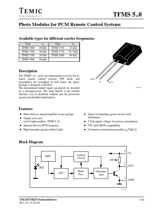
INFRARED RECEIVER MODULE MIM-5xx5K3F DescriptionFeaturesl Photo detector and preamplifier in one packagel Internal filter for PCM frequencyl High immunity against ambient lightl Improved shielding against electric field disturbancel 5.0-Volt supply voltage; low power consumptionl TTL and CMOS compatibilityMIM-5xx5K3F Series Modelsl MIM-5335K3F 33.0KHz l MIM-5385K3F 38.0KHzl MIM-5365K3F 36.0KHz l MIM-5565K3F 56.7KHzl MIM-5375K3F 36.7KHzBLOCK DIAGRAMREV: A1Absolute Maximum RatingsItem Symbol Ratings Unit RemarkSupply voltage Vs-0.3 ~ 5.5VSupply Current Is 2.5mAOperating temperature T opr-25 ~ + 85o CStorage temperature T stg-25 ~ + 85o CSoldering temperature T sd260o C t≦5 s, 1mm from caseElectro-optical characteristics (Vcc=5.0V)Parameter Symbol Min.Typ.Max.Unit RemarksSupply Voltage Vs 4.5 5.0 5.5VCurrent consumption Icc 1.6 2.0mA Under no signal Response wavelength λp940nmOutput form - - - - - active low output - - - - -H level output voltage V0h 4.2VL level output voltage V0l0.5VH level output pulse width Twh400800μsL level output pulse width Twl400800μsDistance between emitter & detector L10.0m NOTE 1Half angle∆θ±45deg Horizonal directionTest MethodA. Standard TransmitterREV: A1B. Detection Length TestC . Pulse Width TestApplication CircuitREV: A1Dimensions in mmREV: A1CHARACTERISTIC CURVES (T A=25o C)REV: A1INFRARED RECEIVER MODULE MIM-5xx5K3F ReliabilityTest item Test condition StandardHigh temparature Ta=+80o C t=240H Note 2.High temp. & high humi.Ta=+40o C 90%RH t=240H Note 2.Low temparature Ta= -25o C t=240H Note 2.Heat cycle -25o C(0.5H) ~ +80o C(0.5H) 20cycle Note 2.Dropping Test devices shall be dropped 3 times naturally Note 3.onto hard wooden board from a 75cm height position.NOTE 1. Distance between emitter & detector specifies maximum distance that output wave form satisfiesthe standard under the conditions below against the standerd transmitter.(1)Measuring place ………Indoor without extreme reflection of light.(2)Ambient light source… Detecting surface illumination shall be 200±50Lux under ordinaryhite fluorescense lamp of no high frequency lighting.(3)Standard transmitter … Burst wave indicated in Fig 1. of standard transmittershall be arranged to 50mVp-p under the measuring circuit specified in Fig 2.NOTE 2. (electro-optical charactistics) shall be satisfied after leaving 2 hours in the normal temperature .NOTE 3. (electro-optical charactistics) shall be satisfied and no conoid deformsand destructions of appearance .(excepting deforms of terminals)Inspection standard1.Among electrical characteristics , total number shall be inspected on items blow.1-1 front distance between emitter & detector1-2 Current consumption1-3 H level output voltage1-4 L level output voltage2.Items except above mentioned are not inspected particularly , but shall fully satisfyCAUTION ( When use and storage of this device )1.Store and use where there is no force causing transformation or change in quality .2.Store and use where there is no corrosive gas or sea(salt) breeze .3.Store and use where there is no extreme humidity .4.Solder the lead-pin within the condition of ratings. After soldering do not add extra force .5.Do not wash this device . Wipe the stains of diode side with a soft cloth. You canuse the solvent , ethylalcohol or methylalcohol or isupropylene only .6.To prevent static electricity damage to the Pre-AMP make sure that the human body, the soldering iron is connected to ground before using .7.Put decoupling device between Vcc and GND for reduse the noise from power supply line .8.The performance of remote-control system depends on environments condition and abilityof periferal parts. Customer should evaluate the performance as total system in those conditionsafter system up with components such as commander , micon and this receiver module .Others1.This device is not design to endure radiative rays and heavily charged particles .2.In case where any trouble or questions arise,both parties agress to make full discussioncovering the said problem .REV: A1。