山武-AZBIL-使用说明书-数字显示调节仪-SLC-SDC23M-24M
- 格式:pdf
- 大小:428.82 KB
- 文档页数:3

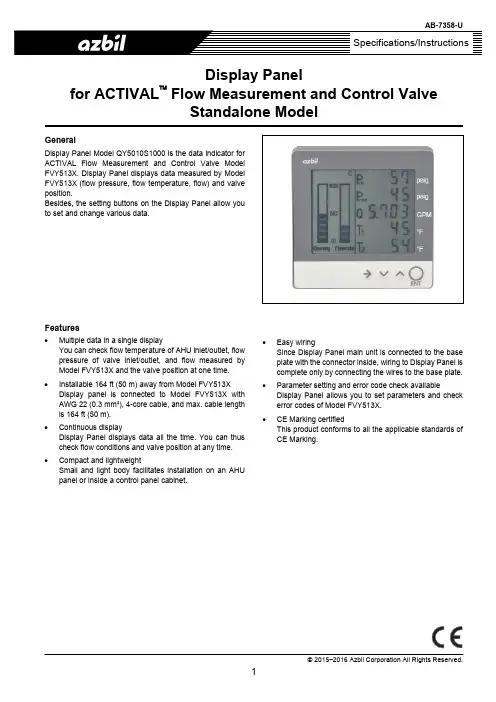
© 2015–2016 Azbil Corporation All Rights Reserved.Display Panelfor ACTIVAL ™ Flow Measurement and Control ValveStandalone ModelGeneralDisplay Panel Model QY5010S1000 is the data indicator for ACTIVAL Flow Measurement and Control Valve ModelFVY513X. Display Panel displays data measured by Model FVY513X (flow pressure, flow temperature, flow) and valve position.Besides, the setting buttons on the Display Panel allow you to set and change various data.Features∙Multiple data in a single displayYou can check flow temperature of AHU inlet/outlet, flow pressure of valve inlet/outlet, and flow measured by Model FVY513X and the valve position at one time. ∙Installable 164 ft (50 m) away from Model FVY513XDisplay panel is connected to Model FVY513X with AWG 22 (0.3 mm²), 4-core cable, and max. cable length is 164 ft (50 m).∙ Continuous displayDisplay Panel displays data all the time. You can thus check flow conditions and valve position at any time. ∙Compact and lightweightSmall and light body facilitates installation on an AHU panel or inside a control panel cabinet.∙ Easy wiringSince Display Panel main unit is connected to the base plate with the connector inside, wiring to Display Panel is complete only by connecting the wires to the base plate. ∙Parameter setting and error code check availableDisplay Panel allows you to set parameters and check error codes of Model FVY513X.∙CE Marking certifiedThis product conforms to all the applicable standards of CE Marking.AB-7358-USafety InstructionsPlease read instructions carefully and use the product as specified in this manual. Be sure to keep this manual nearby for quick reference.Usage RestrictionsThis product is targeted for general air conditioning. Do not use this product in a situation where human life might be affected. Also, do not install this product in an atmosphere containing explosive gas or flammable gas.If this product is used in a clean room or a place where particularly high reliability or control accuracy is required, please contact our sales representative. Azbil Corporation will not bear any responsibility for the results produced by the operators.Warnings and CautionsWARNING Alerts users that improper handling may cause death or serious injury.CAUTION Alerts users that improper handling may cause minor injury or material loss.SignsAlerts users possible hazardous conditions caused by erroneous operation or erroneous use. The symbol inside I indicates the specific type of danger.(For example, the sign on the left warns of the risk of electric shock.)Notifies users that specific actions are prohibited to prevent possible danger. The symbol inside Q graphically indicates the prohibited action.(For example, the sign on the left notifies that disassembly is prohibited.)Instructs users to carry out a specific obligatory action to prevent possible danger. The symbol inside d graphically indicates the actual action to be carried out.(For example, the sign on the left indicates general instructions.)WARNINGBefore wiring or maintenance, be sure to turn off the power to the product.Failure to do so might cause electric shock or device failure.CAUTIONInstall and use the product under the operating conditions (for temperature, humidity, power, vibration, shock, mounting direction, atmospheric condition, etc.) as listed in the specifications.Failure to do so might cause fire or device failure.Installation and wiring must be performed by qualified personnel in accordance with all applicable safety standards. All wiring must comply with applicable codes and ordinances.Take anti-lightening measures based on regional and building characteristics.Lightening might cause fire or critical damage to the products without the anti-lightening measures.If more than the rated power voltage is applied to the product, replace the product with new one for your safety.Failure to do so might cause device failure or overheating.Do not disassemble the product.Doing so might cause device failure.Dispose of the product as industrial waste in accordance with your local regulations.Do not reuse all or part of this product.AB-7358-U IMPORTANT:In case an Azbil Corporation product fails, you are required to provide your Equipment with safety design suchas fool-proof design*1, and fail-safe design*2 (anti-flame propagation design, etc.), whereby preventing anyoccurrence of physical injuries, fires, significant damage, and so forth. Furthermore, fault avoidance*3, faulttolerance*4, or the like should be incorporated so that the said Equipment can satisfy the level of reliability andsafety required for your use.*1. A design that is safe even if the user makes an error.*2. A design that is safe even if the device fails.*3. Avoidance of device failure by using highly reliable components, etc.*4. The use of redundancy.Note: This equipment has been tested and found to comply with the limits for a Class A digital device, pursuant to part 15 of the FCC Rules. These limits are designed to provide reasonable protection against harmful interference when theequipment is operated in a commercial environment. This equipment generates, uses, and can radiate radio frequencyenergy and, if not installed and used in accordance with the instruction manual, may cause harmful interference to radiocommunications. Operation of this equipment in a residential area is likely to cause harmful interference in which casethe user will be required to correct the interference at his own expense.Model NumberModel number DescriptionQY5010 Base model number of Display Panel for Model FVY513XS1000S-001 Power supplied from ACTIVAL Flow Measurement and Control Valve standalone model (Model FVY513X)SpecificationsItem Specification Power supply 12 V DC ± 1 V (supplied from Model FVY513X)Power consumption Max. 0.1 VACable AWG 22 (0.3 mm2) , 4-core cableEnvironmental conditions Rated operatingcondition*1Ambient temperature 32 ︒F to 122 ︒F (0 ︒C to 50 ︒C)Ambient humidity 10 % RH to 85 % RH (non-condensing)Vibration 19.4fps2 (5.9 m/s2), 10 Hz to 150 Hz Transport/storageconditionsAmbient temperature -4 ︒F to 158 ︒F (-20 ︒C to 70 ︒C)Ambient humidity 10 % RH to 85 % RH (non-condensing)Vibration 32.2fps2 (9.8 m/s2), 10 Hz to 150 HzEnclosure rating IEC IP40 (dustproof)Display*2Device Liquid Crystal Display (LCD)Items to display Pvin Valve inlet pressure (psig)Pvout Valve outlet pressure (psig)Q Actual flow (GPM)T1 Coil inlet temperature (︒F)T2 Coil outlet temperature (︒F)HC Heat/CoolE ErrorOpening Actual valve position (% in bar graph)Flowrate Actual flow rate (% in bar graph) Communication Transmissionsystem AP-bus (RS-485 communication)Transmission speed 4800 bpsTransmission distance Max. 164 ft (50 m)Number of Display PanelconnectableOne per single Model FVY513XMaterials Case Modified polyphenylene ether (PPE)Base plate Modified polyphenylene ether (PPE)Face plate Polyester (PET)Accessory - Two tapping screws (M4) for mounting- Two 'kPa' unit stickersWeight 0.33 lb (150 g)Notes:*1 LCD service life may shorten if Display Panel is used in an environment with high temperature and humidity. *2 For display accuracy, refer to specification data of Model FVY513X.AB-7358-URecommended Wire SpecificationsCable typeWiring lengthAWG 22 (0.3 mm 2), 4-core(Cable is not supplied with Display Panel.)164 ft (50 m)OptionItem Note Waterproof boxPart No. 83170324-001 Required when Display Panel is installed outdoors.CE Marking ConformityThis product complies with the following Electromagnetic Compatibility (EMC).EMC : EN61326-1 Class A Table 2 (For use in an industrial electromagnetic environment)DimensionsOutside dimensionsFigure 1. Outside dimensionsMounting dimensions of the base plateFigure 2. Mounting dimensions of the base plate1.89" (48 mm) 1.89" (48 mm)1.30" (33 mm)0.59" (15 m m )2.60" (66 m m )Mounting holesCable conduitHook to remove the casefrom the base plate0.59" (15 m m )2.03" (51.5 m m )3.78" (96 mm)3.78" (96 m m )Base plate CaseAB-7358-U Parts IdentificationFigure 3. Parts identification from the base plate Face plateInsertion guide (female)LCD Insertion guide (male)AB-7358-UItems to be displayed on LCDAnalog values such as pressure, flow, and temperature are displayed on the LCD. Setting buttons set/change various parameters and display error description (when an error occurs). Be sure to enable the parameter setting (Parameter 60) before changing any parameters. For details, see AB-7363-U Instruction Manual of ACTIVAL Flow Measurement and Control Valve Standalone Model .Analog values display screenAnalog values display screen appears on the LCD when you turn on the Display Panel.Figure 4. Analog values display screenDisplay areaDescriptionDisplay rangeUnit Item Display Panel connected to: Range 1 Pvin Valve inlet pressure Model FVY5137 0 to 160 psig Model FVY513E 0 to 320 psig 2PvoutValve outlet pressureModel FVY5137 0 to 160 psig Model FVY513E0 to 320psig 3 QActual flow0.000 to 999.9 GPM 4 T 1Coil inlet temperature 14 to 212 °F 5 T 2Coil outlet temperature14 to 212°F Opening Valve position indicated in a bar graph 0 to 100 (with every 10 % increment) % Flowrate Flow indicated in a bar graph 0 to 100 (with every 10 % increment) % E Error occurred ([E] flashes.)− − H C AHU operation mode ([H]: Heat / [C]: Cool)−−Setting buttonsFunction[→] Cursor button Not used in the analog values display screen.[∨] Down button Press this button to switch to the error display screen when the error indicator [E] flashes. [∧] Up buttonPress this button to switch to the error display screen when the error indicator [E] flashes. [ENT] Enter buttonPress and hold this button to switch to the parameter setting screen.Heat/Cool operation modeindicatorDisplay area 1Enter buttonError indicatorDisplay area 2Display area 3 Display area 4Display area 5Up button Down button Cursor button Valve position in bar graphFlow rate in bar graphAB-7358-U● Parameter setting screenPress and hold the [ENT] button to switch to the parameter setting screen from the analog values display screen.Figure 5. Parameter setting screenDisplay area Display item1indicating the parameter setting screen2 Parameter number3 Current setpoint set for the parameter shown in thedisplay area 2.4 No item displayed5 No item displayedSetting buttons Function [→] Cursor button Press this button to select the digit of theparameter number and of the setpoint. The selected digit flashes.[∨] Down button Press this button to change the selected digit.[∧] Up button Press this button to change the selected digit.[ENT] Enter button Press this button to finally set the changedparameter.Press and hold this button to go back to the analog values display screen.Note:No button operation for continuous 10 minutes on the parameter setting screen will automatically switch from the parameter setting screen to the analog values display screen.● Error display screenFigure 6. Error display screenDisplay area Display item [E] Error occurred 1indicating the error display screen2 Error code3 No item displayed4 No item displayed5 No item displayedSetting buttons Function [→] Cursor button Not used in the error display screen. [∨] Down button Press this button to go back to the analogvalues display screen.[∧] Up button Press this button to go back to the analogvalues display screen.[ENT] Enter button Not used in the error display screen. Note:For details of the error codes, refer to AB-7363-U Instruction Manual of ACTIVAL Flow Measurement and Control Valve Standalone Model .Display area 1Display area 2Display area 1Display area 2Display area 3AB-7358-UWiring and InstallationWARNINGBefore wiring or maintenance, be sure to turn off the power to the product.Failure to do so might cause electric shock or device failure.Wiring1) Press the hook on the bottom of the base plate and detach the case.2) Use 0.22" Dia. to 0.24" Dia. (5.5 mm Dia. to 6.0 mm Dia) cable (AWG 22 (0.3 mm2) , 4-core cable recommended) forconnection. Strip 0.20" to 0.24"(5 mm to 6 mm) sheath of each lead wire. (See Fig. 7.)3) Refer to the wiring label (attached to the base plate) and insert stripped lead wires to each terminal.TerminalsarrangementTerminal number Type Lead wire color*1 12 V DC (+) Red (RED)2 0 V Black (BLK)3 AP-bus (+) White (WHT)4 AP-bus (-) Green (GRN)Note: Lead wire color shown in the above table is the wirecolors of the recommended cable.4) Lock each lead wire with lever lock provided on each terminal. Use a tool such as slotted screwdriver to slide the lever lock.Figure 8. Lead wire connection5) Insert the cable into the slit and fix the cable on the base plate with a cable tie.Figure 9. Cable fixed on the base plate0.20" to 0.24"CableAB-7358-UInstallationIMPORTANT:∙ Do not install this product in an atmosphere containing corrosive gas or explosive gas.∙ Do not install this product in a location exposed to direct sunlight. Direct sunlight accelerates LCD degradation.∙ Waterproof box (optional) is required for the product to be installed outdoors. Ask our sales personnel for the waterproof box.Procedure1) Make two holes for two M4 tapping screws (one for upper and the other for lower sides) on a mounting location, such as anAHU side plate or a panel cabinet. Distance between the centers of upper and lower M4 screws is 2.6" ± 0.08" (66 ± 2 mm). 2) Lead the cable (connected to the base plate terminals) out of the base plate through the base plate conduit (on the bottomright), and mount the base plate on the mounting location with the two M4 tapping screws (accessory of Display Panel).Figure 10. Mounting of the base plate with two M4 tapping screws3) Assemble the case with the base plate by inserting the male insertion guide of the case into the female insertion guide of thebase plate. Four insertion guides are provided on the right and left sides (Two on each side). Press the case well so that the case is completely assembled with the base plate. The case is connected to the base plate with the internal connector.Figure 11. Case assembly with the base plateTwo M4 tapping screwsCable conduit(female)Insertion guides (male)CaseAB-7358-U4) Arrange the cable connected to Display Panel.Cautions for arranging the cable: ∙ Do not pull the cable. ∙ To prevent water from flowing down to Display Panel through the cable, let the cable sag, as Fig. 12 shows. ∙ When installing Display Panel on an AHU side plate, seal the wiring hole on the AHU side plate, as Fig. 12 shows. Damp or dew condensation may damage the Display Panel, otherwise.Figure 12. Cable arrangement5) Film is attached to the front surface (face plate) of Display Panel for protection before shipment. Remove the film beforeactivating Display Panel.6) Display Panel is generally installed on a visible position such as on a wall in a machine room or on a control panel cabinet.However, it may possibly be installed outdoors or in a ceiling. In such a case, install the Display Panel as shown in Figs. 13 and 14. Consider the conditions and requirements of your Display Panel installation and decide the location.Figure 13. Display Panel installed outdoors (in a rainproof box)Display PanelSealing materialCableLet the cable sag.Cable led out of the rear side of Display PanelCable led through the conduit of Display Panel 2" (50 mm) stanchionDisplay Panel in a protection boxDisplay Panel in a protection box directly on a wall2" (50 mm) stanchion Display Panel in a plastic box(commercially available)AB-7358-U If Display Panel needs to be installed in a ceiling, install it near the ceiling access panel. Mount Display Panel in a dustproof box to install in a dusty area in a ceiling.Details of AFigure 14. Display Panel installed in a ceilingWiring to Model FVY513XIMPORTANT:Do not pull the cable connected from the terminals of Display Panel to the terminals of Model FVY513X. Display Panel is used in combination with Model FVY513X. To connect the cable to Model FVY513X, refer to Specification/Installation of Model FVY513X.- AB-7350-U: ACTIVAL Flow Measurement and Control Valve Standalone Model Models FVY5137J (PN10/GG-20)- AB-7354-U: ACTIVAL Flow Measurement and Control Valve Standalone Model Models FVY513EJ (JIS 20K/SCPH2)MaintenanceFor replacement of Display Panel, whole unit must be replaced. Display Panel cannot be partially replaced.Care for the face plateClean the face plate with dry soft cloth. Never use detergent or organic solvent to clean the screen. Otherwise, LCD screen will get scratched, discolored, or deformed.AB-7358-URev. 3.0 Jun. 2016 AB-7358-U。
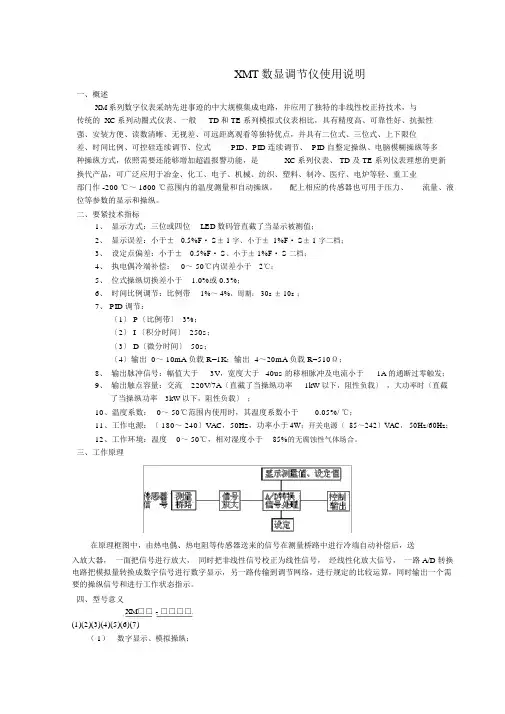
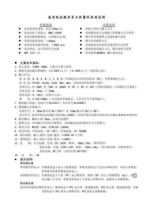
XMT数显调节仪使用说明一、概述XM系列数字仪表采纳先进事迹的中大规模集成电路,并应用了独特的非线性校正持技术,与传统的 XC系列动圈式仪表、一般TD和 TE 系列模拟式仪表相比,具有精度高、可靠性好、抗振性强、安装方便、读数清晰、无视差、可远距离观看等独特优点,并具有二位式、三位式、上下限位差、时间比例、可控硅连续调节、位式PID、PID 连续调节、 PID 自整定操纵、电脑模糊操纵等多种操纵方式,依照需要还能够增加超温报警功能,是XC 系列仪表、 TD 及 TE 系列仪表理想的更新换代产品,可广泛应用于冶金、化工、电子、机械、纺织、塑料、制冷、医疗、电炉等轻、重工业部门作 -200 ℃~ 1600 ℃范围内的温度测量和自动操纵。
配上相应的传感器也可用于压力、流量、液位等参数的显示和操纵。
二、要紧技术指标1、显示方式:三位或四位LED数码管直截了当显示被测值;2、显示误差:小于±0.5%F· S± 1 字、小于± 1%F· S± 1 字二档;3、设定点偏差:小于±0.5%F· S、小于± 1%F· S 二档;4、执电偶冷端补偿:0~ 50℃内误差小于2℃;5、位式操纵切换差小于 1.0%或 0.3%;6、时间比例调节:比例带1%~ 4%,周期: 30s ± 10s ;7、 PID 调节:〔1〕 P〔比例带〕 3%;〔2〕 I 〔积分时间〕 250s;〔3〕 D〔微分时间〕 50s;〔4〕输出 0~ 10mA负载 R=1K;输出 4~20mA负载 R=510Ω;8、输出脉冲信号:幅值大于3V,宽度大于40us 的移相脉冲及电流小于1A 的通断过零触发;9、输出触点容量:交流220V/7A〔直截了当操纵功率1kW以下,阻性负载〕,大功率时〔直截了当操纵功率3kW以下,阻性负载〕;10、温度系数:0~ 50℃范围内使用时,其温度系数小于0.05%/ ℃;11、工作电源:〔 180~ 240〕VAC,50Hz,功率小于4W;开关电源〔 85~242〕VAC, 50Hz/60Hz;12、工作环境:温度0~ 50℃,相对湿度小于85%的无腐蚀性气体场合。
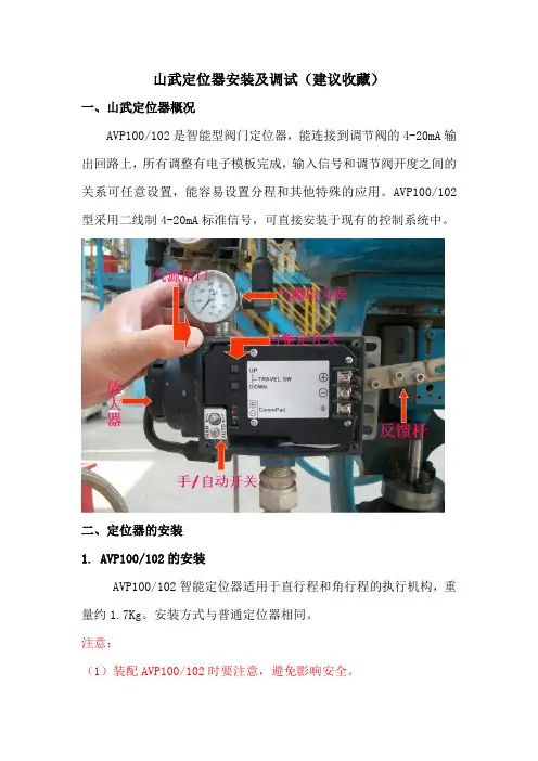
山武定位器安装及调试(建议收藏)一、山武定位器概况AVP100/102是智能型阀门定位器,能连接到调节阀的4-20mA输出回路上,所有调整有电子模板完成,输入信号和调节阀开度之间的关系可任意设置,能容易设置分程和其他特殊的应用。
AVP100/102型采用二线制4-20mA标准信号,可直接安装于现有的控制系统中。
二、定位器的安装1. AVP100/102的安装AVP100/102智能定位器适用于直行程和角行程的执行机构,重量约1.7Kg。
安装方式与普通定位器相同。
注意:(1)装配AVP100/102时要注意,避免影响安全。
(2)不要损坏丝口,如后盖螺纹和其他螺纹。
根据执行机构的尺寸和形式,AVP的选型中已配置了安装板的形式。
如执行机构是特殊形式,AVP也有合适的安装支架,执行机构的校正设置已编入了AVP的程序中。
通过自整定,就能校正AVP。
2、安装步骤(1)、先用两只内六角螺钉把安装板固定在AVP上,拧紧螺钉,并把定位器固定到调节阀执行机构上。
(2)、把执行机构上的反馈销穿定位器反馈杆开孔内。
(3)、反馈杆与反馈销成90度。
(4)反馈杆与AVP本体用两只内六角螺栓固定。
保证反馈杆旋转角最大为±20度,如超过角度,AVP不能正常工作。
(5)在大执行机构上使用延长形反馈杆。
(6)连接气源管,下端为进气口,上端为输出气源口(与执行机构膜头相连)。
连接号气源后在将定位器内的手/自动切换螺钉用螺丝刀向左旋转至水平位,切换至手动。
(7)调节过滤减压阀,使阀门开度到50%,调节反馈销位置,使反馈杆成水平(阀开度为50%),固定反馈销(这一步主要确保供气与反馈杆初始位置的对应关系),切换手/自动螺钉于自动位置。
(8)在直行程的执行机构上,旋转角度为±20度;如超过角度,需延长反馈杆。
3、双气缸(无弹簧)双作用AVP安装安装步骤:(1)安装双作用放大器于AVP的输出口。
(2)输入气源至双作用放大器“SUP”口。
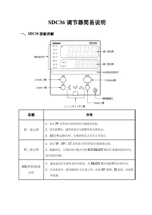
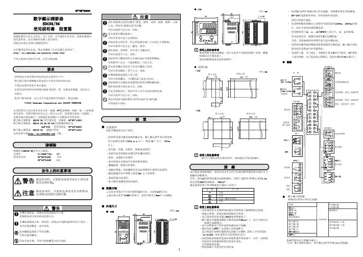
键操作与显示变更○根据有无附加可选项、型号、显示设定(C73~C78)、显示级别(C79)的不同,有不显示的项目。
○设定变更中按[para]键时,将取消操作,并按下记项目显示。
运行显示具体的操作例: 初始设定项目: 运行状态设定项目· 4所示的顺序编号为红字的地方,有注意以下的注意事项在设定了键锁的场合,数值不会闪烁,数值不可变更。
进行数值变更时,请务必解除键锁。
记事本机可由C79设定显示级别: 显示级别可从3种中选择。
显示级别按多功能设定>标准设定>简单设定的顺序,可显示·设定的项目越多。
另外,多功能设定可显示所有的项目。
○ 表中的「●」是多功能设定及标准设定的显示项目。
○ 要改变显示级别、请参阅右下方的2007年3月中文初版(05) 日文初版上海本部 上海市虹桥路3号港汇中心2座2608室 邮编:200300电话:021-********,2336 传真:021-********北京支店 北京市朝阳区朝外大街20号联合大厦1107室 邮编:100020电话:010-********,7572 传真:010-********华南支店 深圳市南山区桃园路1号西海明珠大厦1211、1212室 邮编:518052电话:0755-******** 传真:0755-********计装中心 北京市朝阳区朝外大街20号联合大厦1107室 邮编:100020电话:010-******** 传真:010-********天津办事处 天津市河西区苏州道2号文华国际商务中心1614室 邮编:300203电话:022-********,9260 传真:022-********沈阳办事处 沈阳市和平区南京南街52号鸿源大厦1005室 邮编:110001电话:024-******** 传真:024-********苏州办事处 苏州市西环路6号苏州国际经贸大厦22楼09B单元 邮编:215008电话:0512-******** 传真:0512-********广州办事处 广州市天河区龙口东路5号龙辉大厦508室 邮编:510635电话:020-******** 传真:020-********成都办事处 成都市一环路南一段22号红瓦大厦622室 邮编:610041电话:028-********,6285 传真:028-********厦门联络所 厦门市嘉禾路370号1904第3间 邮编:361000电话:0592-******* 传真:0592-*******香港 香港新界荃湾横龙街77-87号富利工业大厦3号楼电话:00852-21496633 传真:00852-21496600。
sdc40yamatakemanualDownload File › https:///2vA4eIHow to Use the Yamatake SDC40A Digital Indicating ControllerThe Yamatake SDC40A Digital Indicating Controller is a high-precision compact device that can measure and control various types of inputs, such as thermocouple, RTDs, and DC voltage/currents. It features a 5-digit indicator, an input sampling cycle of 100 ms, and an indication accuracy of±0.1% FS ±1U[^1^]. It also has various functions, such as PID control, alarm output, ramp/soak control, and communication interface.sdc40yamatakemanualDownload File › https:///2vA4eIIn this article, we will explain how to use the Yamatake SDC40A Digital Indicating Controller by following these steps:Connect the power supply and input/output wiring according to the wiring diagram in the user 1.manual[^1^].2.Set the input type and range according to the type of sensor or signal you want to measure or control. You can use the front panel keys or the communication interface to set theparameters. Refer to the user manual[^1^] for the details of each parameter.3.Set the control mode and tuning parameters according to your control requirements. You can choose from ON/OFF control, PID control, or manual control. You can also use the auto-tuning function to automatically adjust the PID parameters. Refer to the user manual[^1^] for the details of each control mode and tuning method.4.Set the alarm output and ramp/soak function if needed. You can set up to four alarm outputs with different types and levels. You can also set up to eight ramp/soak segments with different durations and setpoints. Refer to the user manual[^1^] for the details of each alarm output and ramp/soak function.5.Monitor and adjust the process value and setpoint using the front panel display and keys. You can also use the communication interface to send and receive data from a PC or other devices.Refer to the user manual[^1^] for the details of each display mode and key operation.The Yamatake SDC40A Digital Indicating Controller is a versatile and reliable device that can help you achieve optimal control performance in various applications. For more information, please refer to the user manual[^1^] or contact us at ********************.The Yamatake SDC40A Digital Indicating Controller has a user-friendly design that makes it easy to operate and maintain. It has a large and clear LCD display that shows the process value, setpoint, output value, and status indicators. It also has four keys that allow you to access the menu, change the setpoint, switch the display mode, and enter or exit the parameter setting mode. The controller also has a detachable terminal block that simplifies the wiring and replacement process.The Yamatake SDC40A Digital Indicating Controller has a high-performance control algorithm that ensures stable and accurate control. It has a PID control mode that can handle various types of processes, such as temperature, pressure, flow, and level. It also has an ON/OFF control mode that can be used for simple on/off control or as a backup mode in case of PID control failure. The controller also has a manual control mode that allows you to manually adjust the output value.The Yamatake SDC40A Digital Indicating Controller has a flexible communication interface that enables data exchange with other devices. It supports RS-232C and RS-485 communication protocols, and can be configured as a master or a slave device. It can also communicate with up to 31 other controllers using the CMC10L communication module. The controller can send and receive various types of data, such as process value, setpoint, output value, alarm status, parameter values, and error codes.01221423d6。
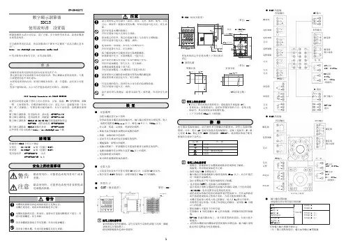
非常感謝您購買數字程序段調節器DCP31確安全使用訂貨・使用時,請務必閱讀下述URL的「訂貨時的承諾事項」、「訂貨時的注意事項」。
/cn/products/order.html要求請務必把本使用說明書送到本産品使用者手中。
禁止擅自複印全部或部分本使用說明書。
禁止轉載本使用說明書。
今後內容變更時恕不事先通知。
本使用說明書的內容,經過仔細審查校對,萬一有錯誤或遺漏,請向本公司提出。
對客戶應用結果,本公司有不能承擔責任的場合,請諒解。
©1996 Yamatake Corporation ALL RIGHTS RESERVEDDigitronic TM、DCP TM和SDC TM是株式會社山武的註冊商標。
安全要求事項 (SAFETY REQUIREMENT)為避免觸電傷人的危險,請遵循此說明書中記載的所有安全注意事項。
此符號用於警告用戶有發生觸電的可能。
・違規操作會破壞本產品的安全保護裝置。
・請勿用本公司指定以外的部件進行更換。
・所有配線操作,僅限經各地方認定、有經驗的操作人員進行。
・請首先連接GND端子。
・請務必在儀錶操作人員可觸及的範圍內設置本產品的主電源切斷開關。
・本產品的主電源配線中,請使用滯後類型(T)﹑額定電流1﹒0A﹑額定電壓250V的保險絲。
(IEC127)・設置保險絲的場合,請把其設置在主電源配線的火線側(非接地側)。
機器的額定值AC100~240V(動作電源電壓:AC90~264V)供給電壓 :50/60Hz電源頻率 :以下消耗功率 :30VA環境條件・請勿在有可燃性液體或氣體的環境下使用,否則會破壞本產品的安全性。
0~50 ℃使用使用溫度範圍 :10~90%RH濕度範圍 :1.96m/s2 以下(10~60Hz X、Y、Z方向各2h)允許振動 :Ⅱ(IEC60364-4-443、IEC60664-1) 過電壓類別 :Category汚染度: Pollution degree 2機器的設置・機器操作人員請勿觸摸機器背面端子,請務必把本產品安裝在儀錶盤上。