ND模块详细版使用说明
- 格式:docx
- 大小:75.92 KB
- 文档页数:5
日精230MHz专业数传电台ND886A/ND889A(使用前请仔细阅读本说明书)©Copyright 2004 byAll rights reservedPrinted in Japan一、ND886A/ND889A外观图及性能特点介绍■尺寸长×宽×高= 44×135×137mm※注:ND886A/ND889A已获得国家信息产业部无线电管理局核发的“无线电发射设备型号核准证”,核准代码分别为:ND886A:CMII ID:2002FJ0359ND889A:CMII ID:2002FJ0712■全新的设计理念:⊙所有收发射频电路采用目前最先进的低噪声场效应(FET)电路设计,高灵敏度、高效率。
⊙完全切合用户需求的专业的线路设计及接口配置,是真正意义上的数传电台,数话兼容。
⊙适用于各类严酷的工作环境,工作温度范围达-40℃~+70℃,真正的工业级产品。
⊙主要功能及参数可通过编程灵活设置,安装操作非常简便;体积紧凑、坚固,屏蔽及散热性极佳。
⊙电台内部预留多个接口,方便用户进行二次开发,内置及外置MODEM、话筒等配套产品一应俱全。
⊙极低的守候电流及发射电流,特别适合于野外需要太阳能电池供电的应用场合。
⊙开放的技术体系,提供先进的编程软件及测试软件,用户可在很短的时间内掌握使用方法。
■广泛的应用领域:日精数传电台/模块适用于各类点对点,一点对多点的无线数据传输系统,如电力负荷监控、配网自动化、水文水情测报、自来水管网监测、城市路灯监控、防空警报控制、铁路信号监控、热网监控、输油供气管网监测、GPS定位、集中抄表、地震测报、电子吊称、自动报靶、防火防盗、环境监测等工业自动化系统。
■功能特点:⊙223—235MHz工作频段内保证各项技术指标,无需调整⊙ 16(或48)个半双工信道,电脑写频,各频道的功率等参数可以独立设置为不同的值⊙ 真正的工业级产品,工作温度范围-40℃∽+70℃,频率稳定度达到±1.5PPM⊙ 收、发射机均采用最先进的FET低噪声放大电路,灵敏度高、杂波小、发热少⊙ ND886A及ND889A的最大功率分别可达15W(FET机型)及28W,物超所值⊙ 5级发射功率、“长发”时限、频响特性及工作模式等可编程设置⊙可遥控改变频道、发射功率及静噪开启灵敏度等参数(此项功能由软件版本决定)⊙发射机“长发”保护、电源逆接保护、电源及天线输入端浪涌保护等多项保护功能⊙耗电省,守候电流小于50mA,节电模式下守候电流≤10mA⊙铝压铸机身,散热快,屏蔽好,抗干扰能力强⊙数话兼容、数传可优先;面板带有DATA收、发指示灯⊙双VCO设计,发射机起动时间小于20ms(FET机型),收发转换快⊙体积紧凑(44×135×137mm)、结构坚固、安装方便⊙可内置或外置多种类型的MODEM,带标准DB-9型I/O口,最高速率19.2Kbps⊙ 极低的误码率: ≤10-7 @-105dBm 2.4kbps。

Operation & Installation InstructionsEQUIPMENT MODULESTable of ContentsEmulator Module (1)Remote Alarm Module (2)4-20 mA Module (3)Solonoid Module (4)Water Quality Monitor Module (8)EMULATOR MODULEMODEL # MOD-EMU-RFThe Emulator module comes with a maleIEP connection (Infinite ExpandabilityPort). Prior to start-up, first ensure all thetoggle switches for the “Module Alarms”and “Lamp Alarm” are in the OFF (toggleup) position. Plug the Emulator connectorinto the IEP on the RAINHARVESTSYSTEMS controller, then plug in thecontroller power cord.To Emulate a particular module failure,toggle the corresponding switch to theON (toggle down) position. The alarmcan be cleared by returning the switch toits OFF (toggle up) position. The devicealso can emulate the UV intensity reported by a UV sensor module. Turning the right “UV” knob in the clockwise direction will increase the intensity, while turning it counterclockwise will decrease the intensity. Please note that to see all the capabilities of the sensor, you will need to cycle the intensity through the range of 49 through 66 %. The “Days Remaining” cycle can also be adjusted by turning the left “Days” knob.MOD-EMU-RFRF seriescontrollersRF-C seriescontrollersIEPconnectionIEPconnection1|P a g e2|P a g eREMOTE ALARM MODULEMODEL # MOD-RAM-RFThe Remote Alarm module comes with both a male and female IEP connection (Infinite Expandability Port). To initiate the module simply plug the male plug into the IEP on the Standard or High Output controller, or into any other RAINHARVEST SYSTEMS module that contains an IEP (sensor, 4-20 mA module, solenoid module, etc.) and then restart the system.The Remote Alarm module is a pair of dry contacts and can be used to connect the controller to a PLC based system, an alarm buzzer (or light), or an “OK” light. The contacts are rated for 230VAC 1A. If your device draws more current, please use the module to switch a relay with contacts rated for the device you wish to use.“OK”LightPower Supply 24 VDC/110V./230V.“FAIL” Light/BuzzerAutodialerPower Supply 24 VDC/110V./230V.remote alarm moduleCom OK Fault remote alarm module ComOKFault Sensor IEP InstallationIEP connectionRF series controllers RF-C series controllers IEP connectionIEP connection3|P a g e4-20 mA MODULEMODEL # MOD-420-RFThe 4-20 mA module comes with both a male and female IEP connection (Infinite Expandability Port). To initiate the module simply plug the male plug into the IEP on the controller, or into any other RAINHARVEST SYSTEMS module that contains an IEP (sensor, remote alarm, solenoid module, etc.)Connect “LOOP” Connections as follows:LOOP Specifications Power Supply: Min 5 voltsMax 30 voltsPower SupplyPLC orData LoggerSensor IEP InstallationconnectionRF series controllers RF-C series controllers IEP connectionIEP connectionSOLENOID MODULEMODEL # MOD-SOL1-RFLOCATIONStep 1) Find a suitable location on the wall for thesolenoid module. The module must be installed closeenough to the controller, or the UV sensor to be ableto plug in the male IEP connector. The module mustalso be installed close enough to the actual solenoidvalve and this distance will be dependent on the cordlength of the particular solenoid valve that is used.Step 2) Pick a location for the solenoid valve andinstall as per the manufacturer’s directions. Thesolenoid module requires bare leads, so if thesolenoid cable has a plug attached, remove the plugand strip the wires to a suitable length.INSTALLATIONStep 1) Make sure the solenoid valve cable is NOT plugged into the electrical outlet. Insert the solenoid valve cable through the center hole of the middle strain relief. Connect the three electrical wires to the terminal block that is marked “SOLENOID” (see Fig. 1). Connect the ground wire in the position marked “GND”, the line voltage wire in the position marked “L1” and the neutral wire in the position marked “N”. Typical wire colour configurations are marked directly on the circuit board to the left of the SOLENOID terminal block to aid in this process (see Fig.2) If you are unsure of the correct wiring configuration for you particular solenoid valve, please contact an approved electrical contractor. Once all the line voltage connectionshave been made, tighten the strain relief nut to secure the cable to the solenoid module.Figure 2Wiring Colour GuideFigure 1Solenoid Wire Installation4|P a g eStep 2) Plug the solenoid valve into the applicable electrical outlet. At this stage, the functionality of the solenoid valve can be tested by pressing the solenoid test button located on the upper left of the circuit board. Manually depressing (and holding) this button will complete the electrical circuit and will open the normally closed solenoid valve. You should be able to hear the activation of the solenoid valve at this stage to ensure the valve is functioning properly (see Fig. 3).Step 3) Make sure your UV controller is unplugged from thepower source. Once all these connections have been made, affix the male IEP plug of the solenoid module cable into the IEP port on the controller, or any other available IEP port such as the UV sensor, 4-20 mA module or remote alarm module. It does not matter which IEP port any module is attached to, as long as they are attached.Figure 3Solenoid Test ButtonOPERATIONStep 1) Plug the RAINHARVEST SYSTEMS controller into the power source and make sure the solenoid module is activated on the controller. During the start-up sequence, the SOLENOID MODULE screen will indicate a “initialized” when the module is activated properly (see Fig. 4).Figure 4 Solenoid ActivationScreens Sensor IEP InstallationIEPconnection RF seriescontrollersRF-C seriescontrollersIEPconnectionIEPconnection5|P a g e6|P a g eStep 2) The controller will only notify you when there is a failure mode whereby the solenoid module (and connected solenoid valve) will be activated. On the RF5 or RF6-C systems, the solenoid module will be activated (shutting off the flow of water) upon LAMP FAILURE (see Fig. 5). To remedy this, replace the UV lamp and restart the system as per the directions outlined in the Owner’s Manual.Step 3) On the RF5 or RF6-C system where a UV sensor is installed, the solenoid module will be activated (shutting off the flow of water) upon a LOW UV condition (less than 50%) (see Fig. 6). To remedy this, you will need to address the reason for this low UV condition which may be due to a dirty UV sensor and quartz sleeve, a lamp that is not emitting enough UV energy, or a change in the water quality. Please refer to the UV systems Owner’s Manual for corrective action procedures.Figure 5LAMP FAILURE ScreenStep 4) To determine what position the solenoid valve is currently in, the solenoid module incorporates three lights on the circuit board (see Fig. 7). When the solenoid is in the OPEN position a green light will appear on the circuit board beside the word “OPEN”. When the valve is CLOSED, a red light will appear on the circuit board beside the word “CLOSED”. And when the solenoid is in an OVERRIDE position, an amber light will appear on the circuit board beside the words “OVERRIDE ON”.Figure 6LOW UV ScreensFigure 7Solenoid Status(Colour)Boil Water Advisory: If any failure occurs on a RAINHARVEST SYSTEMS UV system, the water must not be used for human consumption until the system is returned to a safe operational mode. If the water is used for human consumption during this period, the water must beboiled (minimum 20 minutes at a full boil) prior to consumption.EMERGENCY BYPASSIn a case where the solenoid valve has been activated (valve is closed and no water is allowed to flow), the solenoid module has the ability to bypass the solenoid valve in case of an emergency need of water. To initiate this bypass, depress the button labeled “OVERRIDE” located in the lower left portion of the circuit board (see Fig. 8)7|P a g eFigure 8Solenoid BypassButtonOnce this button has been pressed, the system will remain in this override mode regardless of whether or not the condition causing the solenoid activation has been remedied or not. To reset the system, the power to the controller must be shut off and restarted. While in this override mode the controller will intermittently display a red “SOLENOID OVERRIDE” screen (see Fig. 9).Figure 9SOLENOID OVERRIDEScreenDISABLING EMERGENCY BYPASSIn certain regulated applications, the availability , and use, of the emergency bypass feature may be in violation of the local, state/provincial codes. If this is the case, the bypass feature can easily be disabled by physically removing the bypassbutton. To accomplish this, carefully use a pair of needle nose pliers and physically remove the actual bypass button (marked“OVERRIDE”) from the circuit board .Figure 10SOLENOID FAILUREScreenOTHER FAILURE MODESIn the event there is an issue with the solenoid connection from the IEP cable to the controller, the system will register a “SOLENOIDFAILURE” screen on the controller (see Fig. 10).CAUTION: BEFORE PERFORMING ANY WORK ON THE SOLENOID MODULE, THE POWER CORD MUST BE DISCONNECTED FROM ITS POWER SOURCE (WALL PLUG).8|P a g eWATER QUALITY MONITOR MODULEMODEL # MOD-SHERPA-GThe module comes with a Transmitter and a Remote Display. The Transmitter connects to a standard output and high output controller and transmits the controller’s status wirelessly to the Remote Display. Every Transmitter and Remote Display is paired together and usesencryption to create a reliable and secure communication link between the two devices. Every Transmitter supports up to five Remote Displays. Additional Remote Displays can be purchased and installed separately. Refer to ‘Pairing an Additional Remote Display’ for additional Remote Display installation.Sensor IEP InstallationIEPconnectionRF series controllers RF-C series controllers IEPconnectionIEPconnectionInstallationStep 1) Power off the UV system controller.Step 2) P lug the male plug of the Transmitter into the IEP (Infinite Expandability Port) onthe controller, or into any other module that contains an IEP (sensor, 4-20 mA module, solenoid module, etc.) and then restart the system Note 1.Step 3) T o receive the UV systemcontroller’s status on the Remote Display, plug the AC/DC wall adapter into the Power Port on the Remote Display (5V Max) and slide the switch to the ON position.Back of Remote DisplayTransmitterRemote Display50m/164ft(Note 2)Good CautionAlarmWater QualityMonitorOperationNOTE 1: Not Compatible with MOD-RAM-RF. The module gets detected as a “Remote Alarm” on standard output and high output controllers during the start-up sequence.NOTE 2: The Wireless Range can vary based on the installation environment; objects, walls and metal obstacles can interfere and degrade the wireless signal. Best suited for residential applications.Pairing an Additional Remote DisplayTo pair an additional Remote Display to a currently installed Transmitter:Step 1)P ower ON the Additional Remote Display within 5m (15ft) proximity to the transmitter; by simply plugging the AC/DC wall adapter into the Power Port onthe Remote Display and sliding the switch to the ON position.Step 2)T he Remote Display performs self-pairing with the local transmitter. Once paired the Communication LED on the Remote Display will turn OFF and a Status LEDwill turn ON.Step 3) Once pairing is complete, relocate the Remote Display to any location2.9|P a g ePN#910386Version Date: 04-2019RainHarvest Systems, LLC 4475 Alicia LaneCumming, GA 30028Tel: *********************。

Nanodrop 2000/2000C 分光光度计V1.0 用户守则基因有限公司仪器应用技术支持亲爱的用户,您好!非常感谢您选购我公司代理的仪器。
我们将竭诚为您提供优质的售后服务及免费的专业应用培训。
为了更好地进行仪器的应用培训,我们根据您所选购的仪器特点,将需要您配合准备的工作敬告如下:1. 应用培训内容:仪器操作培训和软件应用培训。
仪器操作培训包括:仪器的操作、维护和仪器使用注意事项。
软件应用培训包括:用户本次所购买的同仪器配套的所有软件的软件应用培训。
2. 培训时间:仪器正式安装调试后,本公司2周内派出专业技术人员进行应用培训。
3. 应用培训中所需准备的试剂、耗材和仪器均需由用户提供,并在系统培训开始前准备好。
我公司将指派专业技术人员免费进行应用培训。
4. 用户签收售后服务工作报告后,基因公司正式的系统培训内容即完成。
您以后在使用的过程中有任何疑问都可以向我们咨询,我们非常乐意为您们解决应用上遇到的问题。
5. 在仪器的使用过程中,无论遇到您认为多么微小或繁琐的问题,请您及时和我们联系,一个及时的通知能节约您的时间,也能帮助我们更好的了解仪器和软件。
6. 联系我们时请您提供:仪器型号、软件名称,版本、错误代码、实验目的、操作系统(98/2k/xp/NT)、维修历史等相关资料。
本守则提的信息仅供参考,本守则包含的所有信息应该是正确和完整的。
如果对本守则中的描述有疑问,请参考厂家的英文操作说明。
如果由于您的不正当使用而对仪器造成损坏或者导致仪器的性能损伤,本公司将不会对此负责。
1.仪器介绍仪器描述Thermo Scientific NanoDrop 2000/2000C 分光光度计可以检测0.5-2ul 的样本,而且检测是非常高的准确性和重复性。
ND2000C 分光光度计不仅提供了NanoDrop 样品保留专利技术的便利性,也可以使用传统的比色皿来进行样本检测。
样本保留系统应用了表面张力来把样本保留在两根检测光纤中间,这使得仪器可以检测较高浓度的样本而不用稀释。
数据传输模块(DM)的安装版本号:CGCC1702V3.01.1概述DM必须正确安装方可达到设计的功能,通常设备的安装必须在我公司认可合格的工程师指导下进行。
0注意事项:请不要带电安装DM。
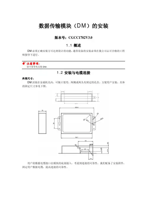
1.2安装与电缆连接外形尺寸:DM封装在金属机壳内,可独立使用,两侧或两头有固定的孔位,方便用户安装,具体的固定尺寸参见下图。
用户的数据电缆接口在模块的底部接入,考虑到连接的可靠性,我们配备了安装附件,固定用户数据电缆,提高连接的可靠性。
安装电缆:数据传输模块(DM)采用16PIN芯间距为3.81mm的单列端子接口。
管脚定义如下图:数据传输模块(DM)工作说明2.2、指示灯的说明指示灯状态说明亮设备电源正常电源(Power)灭设备未上电闪烁有数据收发通信(Act)灭没有数据收发1秒1次,(0.25秒亮,0.75秒灭)处于AT态,正在进行PIN检测2秒1次,(0.5HZ方波,1秒亮,1秒灭)处于AT态,正在进行信号检测2秒1次(0.25秒亮,1.75秒灭)处于AT态,正在进行网络附着/拨号/ppp握手在线(Online)4秒闪1次(0.25HZ方波,0.25秒亮,3.75秒灭)已登陆GPRS网络,并与中心建立连接森兰变频器连接DM 的方法CGCC1702V3.01.森兰SB200型变频器1.1通讯连接变频器的通讯为内置RS485通讯方式,通讯线连接为:485+、485—、GND (地) 1.2通讯参数连接好通讯后需要修改变频器如下的参数方可正常通讯 序号 参数 名称设置值 说明1 FF-00 通讯协议选择 0(默认值) MODBUS2 FF-01 通讯数据格式 1 8E13 FF-02 波特率选择 3(默认值) 96004 FF-03 通讯地址选择1(默认值)5 FF-04 通讯超时检出时间 10.0s6 FF-05 本机应答延时 5ms7 FF-06 通讯超时动作 0 不动作 8FF-08通讯设定频率比例 1.0001.3 DTU 通讯参数9600,8E11.4 注意:通讯参数修改后需要把变频器停电,再上电后参数才有效。
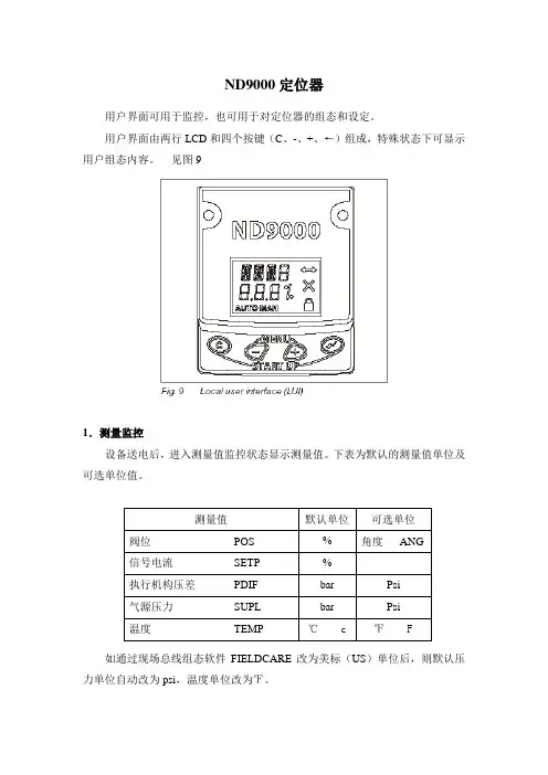
ND9000定位器用户界面可用于监控,也可用于对定位器的组态和设定。
用户界面由两行LCD和四个按键(C、-、+、←)组成,特殊状态下可显示用户组态内容。
见图91.测量监控设备送电后,进入测量值监控状态显示测量值。
下表为默认的测量值单位及可选单位值。
如通过现场总线组态软件FIELDCARE改为美标(US)单位后,则默认压力单位自动改为psi,温度单位改为℉。
按(←)键可即时改变单位。
LCD上行显示当前单位,按住(←)键时同时按(+)或(-)键来选择新的单位,松开按键后即激活(有效输入情况下)。
在1小时内未对定位器进行各种操作,则LCD显示屏滚动显示各测量值。
见图102.快速设置快速设置可对ND-9100F定位器、执行机构、调节阀配置的主要参数进行快速浏览,在核对参数后,最好进行阀门的行程校验。
同时按下(C)键和(←)键可进入快速设置菜单,再按(C)键可取消任何操作。
取消后回到上级用户界面。
主要组态参数如下,详细内容见4.5部分阀门类型 VTYP执行机构形式 ATYP定位器故障位置 PFA阀旋转方向 ROT阀死区 AO改变任一参数后必须重新进行整阀的校验,详细内容见6部分。
见图113. 组态该用户界面是一菜单结构,在测量监控状态下,同时按(+)键和(-)键就进入组态菜单。
然后再按(+)键或(-)键来选择相应菜单。
见图124.模式菜单若用户要改变阀门的操作模式,可在MODE选择行按(←)键,此时MODE 会闪烁。
再按(+)键或(-)键可改变当前操作模式,最后按(←)键确认所选择的模式,有二个操作模式可供选择。
4.1 自动(AUTO)在自动模式下,定位器接受总线上的信号控制阀们的位置。
该模式为正常的工艺服务时使用。
发生信号故障后,定位器会采用在AUTO状态下的输入信号,使阀门保持原位。
4.2 手动(MAN)在手动模式下,可通过手按(+)键或(-)键来控制阀门的位置。
由于手操的阀位不保存到定位器的内存中,所以当信号故障后阀门也不会返回原来位置,但此时可通过手操(+)或(-)回到该阀位。
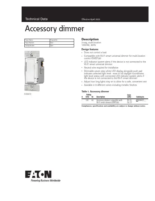
Description3-way, multi-location 120V/AC, 60HzDesign features• Does not control a load•Compatible with Wi-Fi smart universal dimmer for multi-location control (EWDF30)•LED indicator system alerts if the device is not connected to the Wi-Fi smart universal dimmer • Neutral wire required for installation•Dimmable seven step white LED display alongside push pad indicates selected light level - even in full daylight (coordinates light level status with connected LED indicator system alerts if the device is not connected to the Wi-Fi smart dimmer)• Adjust how long lights stay on to allow for a safe, convenient exit •Available in 8 different colors including metallic finishesProject Name:Prepared By:Project Number:Date:Catalog Number:Type:Compliances, specifications and availability are subject to change without notice.EWACDT able 1. Accessory dimmerRating DescriptionColor suffixCatalog no.AV/AC Hz-12060Accessory dimmer compatible with Wi-Fi smart dimmer (EWFD30)W, C2, C6, C7EWACD__Accessory dimmer2EATON /connectedhomeTechnical DataEffective April 2023Accessory dimmer can be wired with Wi-Fi smart dimmer (EWFD30) to provide multi-location ON/OFF/BRIGHT/DIM control. Accessory dim-mer will need to be wired with the load controlling dimmer using a single 3-way wire.ApplicationProject Name:Prepared By:Project Number:Date:Catalog Number:Type:Compliances, specifications and availability are subject to change without notice.Catalog No.EWACDPerformanceRating: 120V/AC, 60HzInstallation & programming For installation and programming the device, see the Accessory Dimmer Quick Start Guide included with product.Testing & code compliance cULus Listed 6B28. NOM Certified.TerminationsAccessory dimmers have four screw terminals for line, ground, neutral and 3-way Material characteristics Flammability: Meets UL94 requirements; V2 rated Temperature rating: 32°F to 104°F (0°C to 40°C)Warranty2-year limited product warrantyT able 2. SpecificationsT able 3. Color ordering informationFor ordering devices, include Catalog No. followed by the Color Suffix: W (White),C2 (Color Change Kit: LA, W, V), C6 (Color Change Kit: W, RB, SG), C7 (Color Change Kit: B, BK, GY)Figure 1. EWACD Product dimensionsTwo location control (requires one Wi-Fi smart dimmer and one accessory dimmer EWACD)EWACDAccessory dimmerC2 Color KitLA (Light Almond), W (White),V (Ivory)C7 Color KitB (Brown), BK (Black), GY (Gray)C6 Color KitRB (Oil Rubbed Bronze), W (White),SG (Silver Granite)Technical DataEffective April 2023Project Name:Prepared By:Project Number:Date:Catalog Number:Type:Certifications & compliancesKEY:cULusNOMRelated productsCompliances, specifications and availability are subject to change without notice.WallplatesPJS26, PJS262Wi-Fi smart productsEWFD30, EWFSW15, EWFTRCR15Multiple Locations using up to four accessory dimmers (EWACD)Accessory dimmerElectrical Sector 1123 Hwy 74 SPeachtree City, GA 30269United States /WifiSmartElectrical Sector Canada Operations 5925 McLaughlin RoadMississauga, Ontario, L5R 1B8CanadaEatonCanada.ca/WifiSmartElectrical Sector Mexico Operations Carr. Tlalnepantla -Cuautitlan Km 17.8 s/n Col. Villa Jardin esq.Cerrada 8 de MayoCuautitlan, Mexico CP 54800Mexico Eaton.mx/WifiSmartEaton1000 Eaton Boulevard Cleveland, OH 44122United States Eaton is a registered trademark. All other trademarks are property of their respective owners.© 2023 EatonAll Rights Reserved Printed in USAPublication No. TD610143EN April 2023。

N D模块使用说明Document serial number【NL89WT-NY98YT-NC8CB-NNUUT-NUT108】N588D MP3 模块说明与使用(技术交流文档)1、N588D MP3 语音芯片模块功能N588D语音芯片是一款功能强大的可重复擦除烧写的语音单片机芯片。
N588D让语音芯片不再为控制方式而寻找合适的外围单片机电路,高度集成的单片机技术足于取代复杂的外围控制电路。
配套N588D VoiceChip上位机操作软件可随意更换N588D语音单片机芯片的任何一种控制模式,把信息下载到SPI-Flash上即可。
这一块软件操作方式简洁易懂,撮合了语音组合技术,大大减少了语音编辑的时间。
完全支持在线下载,即便是N588D通电的情况下,一样可以通过下载器给关联的SPI-Flash下载信息,给N588D语音芯片电路复位一下,就能更新到刚下载进来的控制模式。
支持插入静音模式,插入静音不占用SPI-Flash内存的容量,一个地址位可插入10ms~25min的静音;MP3控制模式下,完全迎合市场上MP3的播放/暂停、停止、上一曲、下一曲、音量+、音量-等功能;按键控制模式下触发方式灵活,可随意设置任意按键为脉冲可重复触发、脉冲不可重复触发、无效按键、电平保持不可循环、电平保持可循环、电平非保持可循环、上一曲不循环、下一曲不循环、上一曲可循环、下一曲可循环、音量+、音量-、播放/暂停、停止、播放/停止等15种触发方式,最多可用10个按键触发控制输出;3×8按键组合控制模式下能以脉冲可重复触发的方式触发24个地址位语音,所触发地址位语音可在0~219之间设置;并口控制模式可用8个控制端口进行控制,仅限于N588D-32L、NW-28P;一线串口控制模式可通过发码端控制语音播放、停止、循环播放和音量大小,或者直接触发0~219地址位的任意语音,发码速度600us~2000us;三线串口控制模式和三线串口控制控制端口扩展输出模式之间可通过发码切换,三线串口控制模式下,能控制语音播放、停止、循环播放和音量大小,或者直接触发0~219地址位的任意语音,三线串口控制控制端口扩展输出可以扩展输出8位,在两种模式下切换,能让上一个模式的最后一种状态保持着进入下一个模式。
NDD380电动机保护控制装置1 装置简介 ----------------------------------------------------------------------------------------------------------------------- - 3 -1.1 适用范围 ---------------------------------------------------------------------------------------------------------------- - 3 -1.2 产品特点 ---------------------------------------------------------------------------------------------------------------- - 3 -2 技术参数 ----------------------------------------------------------------------------------------------------------------------- -3 -2.1 环境参数 ---------------------------------------------------------------------------------------------------------------- - 3 -2.2 额定电气参数 ---------------------------------------------------------------------------------------------------------- - 3 -2.3 主要技术指标 ---------------------------------------------------------------------------------------------------------- - 3 -2.4 通信接口 ---------------------------------------------------------------------------------------------------------------- - 3 -2.5 电磁兼容 ---------------------------------------------------------------------------------------------------------------- - 4 -2.6 机械结构 ---------------------------------------------------------------------------------------------------------------- - 4 -2.6.1 机箱尺寸及开孔图 ------------------------------------------------------------------------------------------- - 4 -2.6.2 面板布置图及端子图 ---------------------------------------------------------------------------------------- - 4 -3 功能原理 ----------------------------------------------------------------------------------------------------------------------- - 5 -3.1 功能配置 ---------------------------------------------------------------------------------------------------------------- - 5 -3.1.1 保护功能-------------------------------------------------------------------------------------------------------- - 5 -3.1.2 测量显示功能-------------------------------------------------------------------------------------------------- - 5 -3.1.3 控制功能-------------------------------------------------------------------------------------------------------- - 5 -3.1.4 事件记录-------------------------------------------------------------------------------------------------------- - 5 -3.1.5 通信功能-------------------------------------------------------------------------------------------------------- - 5 -3.1.6 测试功能-------------------------------------------------------------------------------------------------------- - 5 -3.2 保护原理 ---------------------------------------------------------------------------------------------------------------- - 6 -3.2.1 电流速断保护(短路保护)------------------------------------------------------------------------------- - 6 -3.2.2 堵转保护-------------------------------------------------------------------------------------------------------- - 6 -3.2.3 温度保护-------------------------------------------------------------------------------------------------------- - 6 -3.2.4 起动超时保护-------------------------------------------------------------------------------------------------- - 6 -3.2.5 欠负荷保护----------------------------------------------------------------------------------------------------- - 6 -3.2.6 负序过流保护-------------------------------------------------------------------------------------------------- - 6 -3.2.7 零序过电流保护 ---------------------------------------------------------------------------------------------- - 6 -3.2.8 过电压保护----------------------------------------------------------------------------------------------------- - 6 -3.2.9 低电压保护----------------------------------------------------------------------------------------------------- - 6 -3.2.10 TV断线 -------------------------------------------------------------------------------------------------------- - 7 -3.2.11欠功率因数保护---------------------------------------------------------------------------------------------- - 7 -3.2.12 热过载保护 --------------------------------------------------------------------------------------------------- - 7 -3.2.13 热过载闭锁合闸--------------------------------------------------------------------------------------------- - 7 -4 电动机控制及其它功能 ------------------------------------------------------------------------------------------------------ - 8 -4.1电动机的运行状态----------------------------------------------------------------------------------------------------- - 8 -4.2启停操作 ----------------------------------------------------------------------------------------------------------------- - 8 -4.3保护/控制 ---------------------------------------------------------------------------------------------------------------- - 8 -4.4故障信息输出 ----------------------------------------------------------------------------------------------------------- - 8 -4.5复归方式 ----------------------------------------------------------------------------------------------------------------- - 8 -4.6操作权限--------------------------------------------------------------------------------------------------------------- - 8 -4.7 登录密码 ---------------------------------------------------------------------------------------------------------------- - 8 -5 典型应用 ----------------------------------------------------------------------------------------------------------------------- - 9 -5.1 端子定义 ---------------------------------------------------------------------------------------------------------------- - 9 -5.2工作模式 ---------------------------------------------------------------------------------------------------------------- - 10 -5.2.1 保护模式------------------------------------------------------------------------------------------------------- - 10 -5.2.2 直接起动模式------------------------------------------------------------------------------------------------- - 11 -5.2.3 双向起动模式------------------------------------------------------------------------------------------------- - 12 -5.2.4 星/三角起动两继电器模式 -------------------------------------------------------------------------------- - 13 -5.2.5 星/三角起动三继电器开环模式-------------------------------------------------------------------------- - 14 -5.2.6 星/三角起动三继电器闭环模式-------------------------------------------------------------------------- - 15 -5.2.7 自耦变压器起动两继电器模式--------------------------------------------------------------------------- - 16 -5.2.8 自耦变压器起动三继电器开环模式 -------------------------------------------------------------------- - 17 -5.2.9 自耦变压器起动三继电器闭环模式 -------------------------------------------------------------------- - 18 -6 界面操作 ---------------------------------------------------------------------------------------------------------------------- - 18 -6.1 面板说明 --------------------------------------------------------------------------------------------------------------- - 18 -6.1.1 信息显示------------------------------------------------------------------------------------------------------- - 18 -6.1.2显示亮度调节 ------------------------------------------------------------------------------------------------- - 19 -6.1.3 键盘 ------------------------------------------------------------------------------------------------------------- - 19 -6.2 运行参数表 ------------------------------------------------------------------------------------------------------------ - 19 -6.3 保护定值表 ------------------------------------------------------------------------------------------------------------ - 20 -6.4 查看显示表 ------------------------------------------------------------------------------------------------------------ - 21 -6.5 按键操作 --------------------------------------------------------------------------------------------------------------- - 22 - 7开关量输入和继电器输出配置--------------------------------------------------------------------------------------------- - 24 -7.1保护模式 ---------------------------------------------------------------------------------------------------------------- - 24 -7.2直接起动模式 ---------------------------------------------------------------------------------------------------------- - 24 -7.3双向起动模式 ---------------------------------------------------------------------------------------------------------- - 25 -7.4星/三角起动和自耦变压器起动两继电器模式 ---------------------------------------------------------------- - 25 -7.5星/三角起动和自耦变压器起动三继电器模式 ---------------------------------------------------------------- - 25 -NDD380电动机保护控制装置1 装置简介1.1 适用范围NDD380电动机保护控制装置是基于高性能DSP处理硬件平台和嵌入式实时操作系统,集保护、控制、通信、测量、监视功能于一体,是智能化、网络化、数字化的低压电机控制产品,主要用于380V小型电动机的保护、管理和控制。
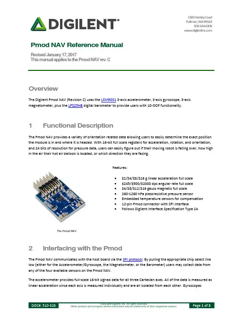
1300 Henley CourtPullman, WA 99163509.334.6306Pmod NAV Reference ManualRevised January 17, 2017This manual applies to the Pmod NAV rev. COverviewThe Digilent Pmod NAV (Revision C) uses the LSM9DS1 3-axis accelerometer, 3-axis gyroscope, 3-axis magnetometer, plus the LPS25HB digital barometer to provide users with 10-DOF functionality.1 Functional DescriptionThe Pmod NAV provides a variety of orientation related data allowing users to easily determine the exact position the module is in and where it is headed. With 16-bit full scale registers for acceleration, rotation, and orientation, and 24 bits of resolution for pressure data, users can easily figure out if their moving robot is falling over, how high in the air their hot air balloon is located, or which direction they are facing.Features:∙±2/±4/±8/±16 g linear acceleration full scale∙±245/±500/±2000 dps angular rate full scale∙±4/±8/±12/±16 gauss magnetic full scale∙260-1260 hPa piezoresistive pressure sensor∙Embedded temperature sensors for compensation∙12-pin Pmod connector with SPI interface∙Follows Digilent Interface Specification Type 2A The Pmod NAV.2 Interfacing with the PmodThe Pmod NAV communicates with the host board via the SPI protocol. By pulling the appropriate chip select line low (either for the Accelerometer/Gyroscope, the Magnetometer, or the Barometer) users may collect data from any of the four available sensors on the Pmod NAV.The accelerometer provides full-scale 16-bit signed data for all three Cartesian axes. All of the data is measured as linear acceleration since each axis is measured individually and are all isolated from each other. Gyroscopesmeasure the angular rotation rate of the module, indicating the degrees per second that the module is being rotated around each axis.The magnetometer detects the magnetic field present around the module, including both the earth's magnetic field as well as the local magnetic environment around it. Each of the three magnetic axis registers provide signed 16-bit full-scale data with up to ±16 gauss sensitivity. Before using the magnetometer, users should run a calibration routine (available in the code example on the Pmod NAV Resource Center) to correct for any hard iron biases that may be present around them.The final component on the Pmod NAV is a barometer with an absolute pressure range of 260 to 1260 hPa which is approximately equivalent to 0.25 to 1.25 atm. Note that as a piezoresistive pressure sensor on the Pmod NAV, you can only measure air pressure with the barometer rather than being able to also measure water pressure.3 Pin Description TablesPin Signal Description1 CS_A/G Chip select for Accel/Gyro2 SDI Master Out Slave In (MOSI)3 SDO Master In Slave Out (MISO)4 SPC Serial Clock5 GND Power Supply Ground6 VCC Power Supply (3.3V/5V)7 INT Interrupt pin for all components8 DRDY_M Data ready for the Magnetometer9 CS_M Chip Select for the Magnetometer10 CS_ALT Chip Select for the Altimeter11 GND Power Supply Ground12 VCC Power Supply (3.3V/5V)Table 1. Header J1 pin descriptions.Pin Signal Description1 INT_M Interrupt for the Magnetometer2 INT_ALT Interrupt for the AltimeterTable 2. Header J2 pin descriptions.Pin Signal Description1 INT1_A/G Interrupt 1 for Altimeter/Gyroscope2 DEN_A/G Data Enable for Altimeter/GyroscopeTable 3. Header JP1 pin descriptions.The Pmod NAV reports to the host board when users bring the appropriate chip select line low to then read the data from the registers on the LSM9DS1.Any external power applied to the Pmod NAV must be within 1.9V and 3.6V; however, it is recommended that Pmod is operated at 3.3V.4 Physical DimensionsThe pins on the pin header are spaced 100 mil apart. The PCB is 0.8 inches long on the sides parallel to the pins on the pin header and 0.8 inches long on the sides perpendicular to the pin header.。
1. ND协议介绍邻居发现协议(Neighbor Discovery Protocol,以下称ND协议)是IPv6的一个关键协议,可以说,ND协议是IPv4某些协议在IPv6中综合起来的升级和改进,如ARP、ICMP路由器发现和ICMP重定向等协议。
当然,作为IPv6的基础性协议,ND还提供了其他功能,如前缀发现、邻居不可达检测、重复地址检测、地址自动配置等。
1.1 IPv6协议格式Version(4-bit):IP版本,该字段值为6Traffic Class(8-bit):流量分类,与IPv4包头的TOS类似Flow Label(20-bit):流标签,用来标记IPv6数据包的一个流Payload Length(16-bit):有效载荷的长度,有效载荷为紧跟IPv6包头的数据包的其他部分Next Header(8-bit):处理选项字段,分段,安全,移动性,松散源路由,记录路由等的新方式。
该字段在承载ND报文时字段值为58(ICMPv6)。
该字段详细字段值对应如下表Value Type of Header0Hop-by-Hop Options Header6TCP17UDP41Encapsulated IPv6 Header43Routing Header44Fragment Header50Encapsulating Security Payload51Authentication Header58ICMPv659No next header60Destination Options HeaderHop Limit:(8-bit):定义IP数据包所能经过的最大跳数,每跳一次将此值减1Source Address(128-bit):IP数据包的源地址Destination Address(128-bit):IP数据包的目的地址1.2 ND报文类型ND协议定义的报文使用ICMP承载,其类型包括:路由器请求报文(RS)、路由器通告(RA)报文、邻居请求报文(NS)、邻居通告报文(NA)和重定向报文。
深圳市雷赛智能控制股份有限公司地址:深圳市南山区学苑大道1001号南山智园A3栋10-11楼邮编:518000电话:400-885-5521传真:*************Email:********************网址:上海分公司地址:上海市淞江区九亭镇涞寅路1881号10栋电话:************传真:************北京办事处地址:北京市朝阳区北苑路13号院office1号楼A单元606号电话:************传真:************ND2282两相高压细分步进驱动器使用手册Version1.0版权所有不得翻印【使用前请仔细阅读本手册,以免损坏驱动器】深圳市雷赛智能控制股份有限公司目录一、产品简介 (2)二、电气、机械和环境指标 (2)三、驱动器接口和接线介绍 (4)四、电流、细分拨码开关设定 (7)五、供电电源选择 (8)六、电机选配 (8)七、典型接线案例 (10)八、保护功能 (12)九、常见问题 (12)十、产品保修条款 (14)ND2282两相高压细分步进驱动器一、产品简介1.1概述ND2282是雷赛公司最新推出的一款采用精密电流控制技术设计的高压步进电机驱动器,适合驱动机座号为86~110型各种品牌的两相混合式步进电机。
由于采用了先进的抗噪声控制方法,能大幅度降低电机运转时的噪声和振动,使得步进电机运转时的噪声和平稳性趋近于伺服电机的水平。
和市场上的大多数其它细分驱动器相比,步进电机和驱动器的发热量降幅达15-30%。
1.2特点1.3应用领域适合各种大中型自动化设备和仪器,例如:雕刻机、贴标机、切割机、激光照排、绘图仪、数控机床、拿放装置等。
在用户期望低振动、小噪声、高速度、高精度的设备中应用效果特佳。
二、电气、机械和环境指标2.1电气指标(Tj=25℃)说明ND2282最小值典型值最大值单位输出电流0.7-8.2A输入电源电压70220230Vac控制信号输入电流71016mA步进脉冲频率0-300(16mA输入电流)KHz 脉冲低电平时间2μs绝缘电阻500MΩ2.2使用环境及参数●高性能、低价格、低噪声●高速力矩大●供电电压AC70-150V●输出电流峰值可达8.2A(均值5.86A)●精密电流控制使电机发热大为降低●可驱动4,6,8线两相步进电机●光隔离差分信号输入●单/双脉冲功能●脉冲响应频率最高可达300KHz(更高可选)●电流设定方便,16档可选●细分精度多达15档可选●具有过压、欠压、短路等保护功能冷却方式自然冷却或强制冷却使用环境场合尽量避免粉尘、油雾及腐蚀性气体环境温度0℃—+40℃最高工作温度70℃湿度40%—90%RH(不能结露和有水珠)震动 5.9m/s²Max保存温度-40℃—+70℃重量约1.36kg2.3机械安装图(单位:毫米)外形尺寸:137×200×81图1.安装尺寸图2.4加强散热方式(1)驱动器的可靠工作温度通常在60℃以内,电机工作温度为80℃以内;(2)建议使用时选择自动半流方式,即马达停止时电流自动减一半,以减少电机和驱动器的发热;(3)安装驱动器时请采用竖着侧面安装,使散热齿形成较强的空气对流;必要时机内靠近驱动器处安装风扇,强制散热,保证驱动器在可靠工作温度范围内工作。
User ManualMITSUMI WiFi ModuleMODEL DWM-W014The purpose of this manual is to explain correct way how to integrate module DWM-W014 to the end product. It includes procedures that shall assist you to avoid unforeseen problems. This manual presents information that shows how module and OEM product, where module integrated, complies with regulations in certain regions. Any modifications, not expressly approved by the manufacturer could void the authority to operate in these regions.The MITSUMI WiFi Module, model DWM-W014 has to be installed and used in accordance with the technical description/installation instructions provided by the manufacturer.For detail information concerning type approval of this module (e.g. where this module is already pre-approved) please contact the authorized local distributor or the manufacturer.The system may only be implemented in the configuration that was authorized. Note that any changes or modifications to this equipment not expressly approved by the manufacturer could void the user’s authority to operate this equipment.Regulatory InformationOperational InformationWireless InteroperabilityThe end product integrating this module is designed to be interoperable with any wireless LAN product that is based on direct sequence spread spectrum (DSSS) and orthogonal frequency division multiplexing (OFDM) radio technology and to comply with the following standards.・IEEE Std 802.11b Standard on 2.4GHz Wireless LAN・IEEE Std 802.11g Standard on 2.4GHz Wireless LANSafetyThe end product integrating this module, like other radio devices, emits radio frequency electromagnetic energy. The level of energy emitted by this device, however, is less than the electromagnetic energy emitted by other wireless devices such as mobile phones. The end product integrating this module operates within the guidelines found in radio frequency safety standards and recommendations. These standards and recommendations reflect the consensus of the scientific community and result from deliberations of panels and committees of scientists who continually review and interpret the extensive research literature. In some situations or environments, the use of the end product integrating this module may be restricted by the proprietor of the building or responsible representatives of the applicable organization. Examples of such situations include the following:・Using the end product integrating this module onboard airplanes, or・Using the end product integrating this module in any other environment wherethe risk of interference with other devices or services is perceived or identified asbeing harmful.If uncertain of the policy that applies to the use of wireless devices in a specific organization or environment (an airplane, for example), ask for authorization to use the end product integrated into this module before turning it on.USA-Federal Communications Commission (FCC)This equipment has been tested and found to comply with the limits for a Class B digital device, pursuant to Part 15 of FCC Rules. These limits are designed to provide reasonable protection against harmful interference in a residential installation. This equipment generates, uses, and can radiate radio frequency energy. If not installed and used in accordance with the instructions, it may cause harmful interference to radio communications. However, there is no guarantee that interference will not occur in a particular installation.If this equipment does cause harmful interference to radio or television reception, which can be determined by tuning the equipment off and on, the user is encouraged to try and correct the interference by one or more of the following measures:-Reorient or relocate the receiving antenna.-Increase the distance between the equipment and the receiver.-Connect the equipment to outlet on a circuit different from that to which the receiver is connected.-Consult the dealer or an experienced radio/TV technician for help.This device complies with Part 15 of the FCC Rules.Operation is subject to the following two conditions:(1) This device may not cause harmful interference, and(2) This device must accept any interference received, including interference that may cause undesired operation.Any changes or modifications not expressly approved by the party responsible for compliance could void the user’s authority to operate the equipment.LabelingMITSUMI WiFi module DWM-W014 labelled as below.FCC ID: EW4DWMW014The proposed with FCC ID label format is to be placed on the module. If FCC ID is not visible when the module is installed into the system, “Contains FCC ID: EW4DWMW014” shall be placed on the outside of final host system.Caution: Exposure to Radio Frequency Radiation.To comply with RF exposure compliance requirements, a separation distance of at Least 20 cm must be maintained between the antenna of this device and all persons.This device must not be co-located or operating in conjunction with any other antenna or transmitter.Canada-Industry Canada (IC)This device complies with RSS 210 of Industry Canada.Operation is subject to the following two conditions:(1) This device may not cause interference, and(2) This device must accept any interference, including interference that may cause undesired operation of this device.L ‘ utilization de ce dispositif est autorisée seulement aux conditions suivantes :(1) il ne doit pas produire de brouillage et(2) l’ utilisateur du dispositif doit étre prêt à accepter tout brouillage radioélectrique reçu, même si ce brouillage est susceptible de compromettre le fomctionnement du dispositif.The term “IC” before the equipment certification number only signifies that the Industry Canada technical specifications were met.To reduce potential radio interference to other users, the antenna type and its gain should be so chosen that the equivalent isotropically radiated power (EIRP) is not more than that required for successful communication.To prevent radio interference to the licensed service, this device is intended to be operated indoors and away from windows to provide maximum shielding. Equipment (or its transmit antenna) that is installed outdoors is subject to licensing.Pour empecher que cet appareil cause du brouillage au service faisant l’objet d’une licence, il doit etre utilize a l’interieur et devrait etre place loin des fenetres afinde Fournier un ecram de blindage maximal. Si le matriel (ou son antenne d’emission) est installe a l’exterieur, il doit faire l’objet d’une licence.Caution: Exposure to Radio Frequency Radiation.The installer of this radio equipment must ensure that the antenna is located or pointed such that it does not emit RF field in excess of Health Canada limits for the general population; consult Safety Code 6, obtainable from Health Canada’s website at www.hc-sc.gc.ca/rpb.Europe-EU Declaration of Conformity and RestrictionsHereby, MITSUMI declares that this Mitsumi WiFi module DWM-W014 is in compliance with the essential requirements and other relevant provisions of Directive 1999/5/EC.This equipment is marked with the symbol and can be used throughout the European community.This indicates compliance with the R&TTE Directive 1999/5/EC and meets the relevant parts of following technical specifications:EN 300 328 V1.7.1(2006-10), Electromagnetic compatibility and Radio spectrum Matters (ERM); Wideband Transmission Systems; Data transmission equipment operating in the 2.4GHz ISM band and using spread spectrum modulation techniques; Harmonized EN covering essential requirements under article 3.2 of the R&TTE Directive. EN 301 489-17 V1.2.1 (2002-08), Electromagnetic Compatibility and Radio spectrum Matters (ERM); Electromagnetic Compatibility (EMC) standard for radio equipment and services; Part 17: Specific Conditions for Wideband Data and HYPERLAN Equipment.EN 60950-1, Safety of Information Technology Equipment.EN 50385, Product standard to demonstrate the compliances of radio base stations and fixed terminal stations for wireless telecommunication systems with the basic restrictions or the reference levels related to human exposure to radio frequency electromagnetic fields.Marking by the symbol indicates that usage restrictions apply.To comply with RF exposure compliance requirements, a separation distance of at Least 20 cm must be maintained between the antenna of this device and all persons. This device must not be co-located or operating in conjunction with any other antenna or transmitter.France – 2.4GHz for Metropolitan France :In all Metropolitan départements, wireless LAN frequencies can be used under the following conditions, either for public or private use:・ Indoor use: maximum power (EIRP) of 100mW for the entire 2400-2483.5MHz frequency band・ Outdoor use: maximum power (EIRP) of 100mW for the 2400-2454MHz band and with maximum power (EIRP) of 10mW for the 2454-2483.5MHz band。
【H3C交换机】cpu各个进程的详细说明display cpu-usage命令⽤来查看设备CPU占⽤率的统计信息,以及各个进程的cpu占⽤率。
各个进程详细说明如下,不同软件版本、盒式和框式的cpu进程略有不同,详细信息可以查看⼿册中的命令参考,有关display cpu-usage命令的介绍。
BUFM:输出调试信息的任务1731:实现Y1731协议栈,管理协议状态机,维护协议相关的数据库_EXC:系统异常事件处理任务_TIL:监控、处理软件异常导致的死循环AAA:认证/计费/授权,实现与UCM、RADIUS等模块进⾏交互,处理⽤户认证消息,维护认证与授权表项信息ACL:访问控制列表ADPG:适配层任务,维护动态VLAN相关的芯⽚表项ADPT:实现EFM协议栈处理,管理协议状态机,维护协议相关的数据库age_task:MAC⽼化任务AGNT:实现IPv4 SNMP协议栈AGT6:实现IPV6 SNMP 协议栈ALM:告警信息的添加、清除、管理任务ALS:实现激光器⾃动关闭功能AM:负责地址池以及地址的管理,为DHCP等模块提供地址管理服务AMCP:应⽤层管理控制协议,⽤于SPU单板同步主控板数据APP:负责三层业务任务统⼀调度ARP:实现ARP协议栈,管理协议状态机,维护协议相关的数据库au_msg_hnd :AU消息处理任务,MAC学习和MAC表项下发使⽤AU消息⽅式bcmC:芯⽚端⼝报⽂计数bcmD:实现芯⽚的驱动软件异步处理消息bcmR:提供从芯⽚接收报⽂的功能bcmT:提供向芯⽚发送报⽂的功能bcmX:提供向特定型号芯⽚异步发送报⽂的功能BEAT:板间⼼跳报⽂的发送和接受、监控板间通信是否异常BFD:实现双向链路检测(BFD)协议栈,管理协议状态机,维护协议相关的数据库bmLI:扫描端⼝状态,变化时通知应⽤模块处理BOX:输出⿊盒⼦中存储的信息(⿊盒⼦⽤于记录产品运⾏过程中出现的错误、异常等信息)BULK_CLASS:USB设备类管理任务(如U盘,⿏标属不同CLASS)(操作系统任务)BULK_CLASS_IRP:USB设备类I/O请求包管理任务(操作系统任务)BusM A:USB 总线管理任务(操作系统任务)CCTL:批量性能采集调度任务CDM:管理配置相关数据CFM:配置恢复CHAL:完成硬件适配层功能CKDV:时钟卡控制和管理CMD_Switching:Socket侦听任务CMDA:提供批量执⾏命令的功能cmdExec:命令⾏执⾏任务CSBR:主备⼀致性检测CSPF:实现CSPF协议栈,进⾏路径计算CssC:处理集群产⽣的事件CSSM:实现集群协议栈,管理集群状态DEFD:负责监控上送CPU的流量,维护CPU防攻击相关数据DELM:STP删除MAC的任务DEV:管理设备上的硬件模块DEVA:设备管理处理⼦卡热插拔DFSU:逻辑卡逻辑⽂件加载DHCP:实现DHCP协议栈处理,完成DHCP Snooping及DHCP Relay等功能DLDP:实现完成DLDP协议栈处理,管理协议状态机,维护协议相关的数据库DSMS:设备管理模块处理环境监控系统发送的环境告警EAP:实现提供8021X认证、MAC认证以及旁路认证功能,管理协议状态机,维护协议相关的数据库Ecm:低级板间通信管理ECM:提供低级板间通信功能EFMT:发送3AH的测试报⽂EHCD_IH:USB host控制器驱动任务(操作系统任务)ELAB:管理设备电⼦标签FECD:负责处理MOD同步信息FIB:在主控板⽣成IPv4软转发表项并下发接⼝板,指导转发FIB6:IPV6 FIB表项管理,维护软件表项,并触发适配层维护芯⽚表项FM93:输出监控到的故障信息FMAT:故障管理任务FMCK:设备故障监控检测FMON:实时监控逻辑卡故障frag_add:MAC分段同步硬表到软表,遍历硬表,将软表中不存在的表项添加到软表frag_del:MAC分段同步硬表到软表,遍历软表,如果表项在硬表中不存在,则从软表中删除之FTPS:提供FTP服务功能FTS:FECD创建的收包任务,驱动收到报⽂后,若不是超级任务则把报⽂给FTS任务处理GREP:适配层任务,负责芯⽚GRE转发表项的管理GTL:⽤于为内存、字符串等公共数据提供统⼀的管理GVRP:实现GVRP协议栈处理,管理协议状态机,维护协议相关的数据库HACK:⽤于HA应答消息的处理HOTT:管理接⼝板卡的热插拔HS2M:完成主控板和备板之间数据同步,提供⾼可靠性HVRP:实现HVRP协议栈处理,管理协议状态机,维护协议相关的数据库IFNT:接⼝管理任务,负责接⼝状态变化事件的处理IFPD:提供接⼝管理功能,维护设备的接⼝数据库,处理各种接⼝状态变化事件INFO:接受、输出业务模块产⽣的⽇志、告IP:负责IP协议任务统⼀调度IPCQ:IPC消息发送失败时,进⾏消息报⽂的重传IPCR:IPC消息的发送、接收及分发到对应的业务模块进⾏处理IPMC:适配三层组播协议,相应控制层⾯变化,下发转发表项ISSU:提供系统固件平滑升级的功能ITSK:IPOS公共任务,包括各种协议报⽂的发送、接受及分发等L2:负责⼆层业务任务统⼀调度L2MC:在接⼝板实现IGMP/MLD协议的侦听,实现频道快速加⼊/离开L2V:VPLS,VLL业务管理,维护控制平⾯数据库,并通知适配层维护芯⽚转发表项L3I4:接⼝板下发IPV4单播转发表项L3IO:接⼝板下发URPF、VRRP等三层协议表项L3M4:主控板适配ARP协议处理,下发IPV4单播转发表项、响应控制层⾯变化L3MB:主控板适配URPF、VRRP等三层协议处理,下发转发表项LACP:实现LACP协议栈,管理协议状态机,维护协议相关的数据库LCS:license管理任务LCSP:根据License的内容,完成授权特性的加载LDP:实现LDP协议栈,维护LDP LSP数据库LDRV:提供主备板软件版本同步功能LDT:实现LDT协议栈,管理协议状态机,维护协议相关的数据库LHAL:为业务板提供硬件适配层,屏蔽硬件差异LINK:负责链路层任务统⼀调度linkscan:端⼝link状态检测任务LLDP:实现LLDP协议栈,管理协议状态机,维护协议相关的数据库LOAD:提供业务板版本镜像⽂件、补丁包的加载功能LSPA:负责LSP软件转发表项的维护,并通知适配层维护芯⽚转发表项LSPM:LSP管理任务,负责LSP的创建,更新,删除MCSW:适配三层组播协议,相应控制层⾯变化,下发转发表项MERX:管理⽹⼝收包处理任务MFF:实现MFF功能MFIB:管理三层组播转发表项MIRR:端⼝镜像任务MOD:完成单板模块编号的管理,分配及回收MPLS:实现MPLS协议栈,完成标签的分配、管理、回收MSYN:负责MAC地址在各个单板间的同步MTR:实现内存使⽤状态定时统计功能mv_rx0:CPU 0号收包队列处理任务mv_rx1:CPU 1号收包队列处理任务mv_rx2:CPU 2号收包队列处理任务mv_rx3:CPU 3号收包队列处理任务mv_rx4:CPU 4号收包队列处理任务mv_rx5:CPU 5号收包队列处理任务mv_rx6:CPU 6号收包队列处理任务mv_rx7:CPU 7号收包队列处理任务NSA:VRP NETStream适配层任务,完成芯⽚表项的管理NTPT:实现NTP协议栈,管理协议状态机,维护协议相关的数据库OAM:实现MPLS OAM协议栈,管理协议状态机,维护协议相关的数据库OAM1:适配OAM 1ag协议,响应协议层变化,转发层⾯做相应的处理OAMI:处理从逻辑卡接收报⽂OAMT:适配层任务,响应协议变化,维护芯⽚表项OS:操作系统任务PING:提供ping快速响应功能PNGI:接⼝板ping快回处理任务,提供ping快速响应功能PNGM:主控板ping快回处理,提供ping快速响应功能Port:芯⽚调试命令处理port_statistics:端⼝统计PPI:适配层任务,维护芯⽚中各个接⼝的状态PTAL:实现重定向认证功能,完成认证授权,管理协议状态机,维护协议相关的数据库QOSA:实现QOS配置的管理,维护芯⽚表项QOSB:在接⼝板负责QOS表项的代理下发,维护已经下发的QOS表项RACL:负责根据TCP/UDP/ICMP⾸包建⽴流表,并对建⽴的流表进⾏流量实时监控与⽼化处理RDS:实现radius协议栈处理,管理协议状态机,维护协议相关的数据库RMON:远程系统监控root:系统根任务ROUT:负责各路由协议路由选路以及路由学习,进⾏最优路由的选择并下发FIBRPCQ:提供远程过程调⽤功能RRPP:在接⼝板实现RRPP协议栈,完成端⼝状态快速感知及硬件表项的下发RSA:计算RSA密钥RSVP:实现RSVP协议栈,维护CR-LSP数据库RTMR:⽤于定时任务的管理SAM:在接⼝板接⼊业务相关表项的代理下发,维护已经下发的表项SAPP:负责应⽤层协议字典以及⽩名单管理,维护软件表项并通知适配层设置芯⽚状态SDKD:检测连接背板的端⼝的状态及统计报⽂速率SDKE:⽤于查看LSW芯⽚相关表项信息SECB:在接⼝板负责设备安全表项的代理下发,维护已经下发的安全表项SECE:实现ARP安全、IP安全以及CPU安全等功能,管理协议状态机,维护协议相关的数据库信息SERVER:tcp/ip 服务器任务SFPM:完成光模块⽣产信息和数字诊断信息的查询功能SIMC:模拟CPU占有率故障SLAG:实现E-TRUNK功能SMAG:智能链路代理,快速感知并处理端⼝状态变化事件SMLK:实现Smart link协议栈,管理协议状态机,维护协议相关的数据库smsL:加载环境监控模块smsR:发送环境监控请求消息smsT:为环境监控系统提供报⽂发送功能SNPG:IGMP/MLD-Snooping协议栈,侦听并处理IGMP和MLD协议报⽂SOCK:IP协议栈报⽂调度和处理SRMI:外部中断处理任务SRMT:设备管理定时器任务SRVC:负责与IP SESSION功能相关的DHCP报⽂交互,通过和认证授权以及⽤户管理模块进⾏交互完成授权、计费功能STFW:超级转发任务,主要维护trunk内存中的转发表S**:适配操作系统,协助完成任务、事件调度STP:实现STP协议栈,管理协议状态机,维护协议相关的数据库STRA:实现监控与识别攻击流量,并对攻击源进⾏惩罚的功能STRB:接⼝板监控与识别攻击流量SUPP:设备管理中断消息,定时器消息t1:临时任务(操作系统任务)TACH:实现hwtacacs协议栈处理,管理协议状态机,维护协议相关的数据库TAD:传输告警任务TARP:处理告警信息tBulkClnt:USB插拔驱动管理任务(操作系统任务)TCPKEEPALIVE:TCP连接保持任务TCTL:批量性能采集上传控制任务tDcacheUpd:磁盘cache更新任务(操作系统任务)tExcTask:异常处理任务(操作系统任务)TICK:系统时钟处理任务tLogTask:⽇志任务(操作系统任务)TM:为接⼊业务提供表项维护功能,维护芯⽚表项TRAP:处理告警信息tRlogind:虚拟终端远程登录任务(操作系统任务)tTelnetd:telnet服务端任务(操作系统任务)TTNQ:负责NQA服务器端任务统⼀调度tUsbPgs:USB插拔设备管理任务(操作系统任务)tWdbTask:调试代理任务(操作系统任务)U 34:⽤户命令处理任务UCM:与AAA等模块交互,共同处理⽤户状态,维护⽤户表UDPH:UDP helperUSB:通过USB升级版本任务usbPegasusLib:USB host lib库(操作系统任务)usbPegasusLib_IRP:USB host I/O请求lib库(操作系统任务)UTSK:⽤户框架处理任务,⽤于优化协议栈的处理,保证协议处理的优先级VCON:业务板串⼝信息重定向任务VFS:⽤于管理虚拟⽂件系统VIDL:负责统计CPU空闲情况VMON:⽤于监控系统任务运⾏的轨迹VOAM:提供NQA VPLS MAC 诊断功能VP:接收、发送单板间VP报⽂VPR:接收单板间VP报⽂VPRE:VP消息处理任务VPS:发送单板间VP报⽂VRPT:定时器测试任务VRRP:实现VRRP协议栈,管理协议状态机,维护协议相关的数据库VT:虚拟终端任务VT0:对第⼀个登录设备的⽤户进⾏认证、命令处理VTRU:处理Vtrunk的updown事件VTYD:接受所有⽤户登录处理WEB:实现Web认证功能WEBS:提供⽤户通过Web访问设备的功能XMON:⽤于监控系统任务运⾏的轨迹XQOS:服务质量任务。
ND模块使用说明
一、什么是ND模块?
ND模块是一种用于网络设备实现网络路由功能的半成品产品。
它是
一种典型的框架,涵盖了网络设备必需的硬件实现和软件实现,使得用户
在简洁的架构下实现网络路由。
ND模块可以分为两个部分:硬件模块和
软件模块。
ND模块的硬件由网络接口(如网络端口),处理器,路由器,存储设备等组成,它可以实现网络路由的必要功能。
软件模块则主要包括
管理软件,路由软件,安全软件和控制软件等组成,它实现网络控制,安
全控制,路由管理,数据传输等等功能的组件。
二、ND模块的主要功能
1、网络路由器功能:ND模块具有完整的网络路由器功能,可实现网
络数据包的转发,网络路由选择等功能;
2、网络管理功能:ND模块提供了网络管理功能,可以监控和管理网络,包括网络状态检测,网络设备管理,网络安全管理,网络资源管理等
功能;
3、网络安全功能:ND模块具有完善的网络安全功能,可以检测和拦
截网络攻击,并防止网络恶意攻击;
4、网络传输功能:ND模块具完善的网络传输功能,可以实现多种网
络协议。
ND 统计SDK使用手册for AndroidV2.1目的本文档旨在帮助开发者了解统计的基本功能,以及Android 客户端ND 统计SDK 的接入方法和约束。
接入流程ND 统计支持Android 与IOS 的客户端接入,开发者通过以下流程来接入SDK:创建应用:创建的应用都会分配AppId 与AppKey,其中AppId 是中对应用的唯一标识,ND统计SDK 通过AppId 来鉴别应用的身份,同时AppKey 是为应用分配的密钥,用于保证应用来源的可靠性。
配置后台:开发者需要进入后来配置应用需要统计收集的数据信息。
比如版本,统计数据项的开关等。
集成SDK:根据后台的配置功能入口,在你的应用代码中集成统计库,并调用相关的接口来完成数据的收集。
在下面一节将会详细介绍Android 客户端的SDK 接入方法。
SDK 集成环境配置1) Eclipse 环境配置下载最新版sdk 的rar 包,解压将其中的NdAnalyticsSDK_Android_V2.0.jar 释放到本地目录,Eclipse 用户右键您的工程根目录,选择Properties -> Java Build Path -> Libraries, 然后点击Add External JARs... 选择指向NdAnalyticsSDK_Android_V2.0.jar 的路径,点击OK,即导入成功。
注意,你的应用api-level 必须是>= 4。
2) AndroidManifest.xml 权限配置请在AndroidManifest.xml 加入以下权限:<uses-permissionandroid:name="android.permission.ACCESS_NETWORK_STATE"></uses-per mission><uses-permissionandroid:name="android.permission.READ_PHONE_STATE"></uses-permiss ion><uses-permission android:name="android.permission.INTERNET"/><uses-permissionandroid:name="android.permission.ACCESS_WIFI_STATE"></uses-permis sion>接口功能功能接口定义在com.nd.analytics.NdAnalytics 类中,都是静态方法,下面介绍它的功能:1) 初始化统计功能使用前必须先调用初始化方法,它代表你的程序的一次启动过程。