p2p网络摄像头说明书
- 格式:doc
- 大小:19.48 MB
- 文档页数:16

E n g l i s hPower off the Network Camera as soon asit is found smoking or smelt unusual.Contact your distributor when such caseshappen.Keep the Network Camera away from the water. If the Network Camera is wet, power off immediately.Do not place the Network Camera aroundthe heat sources, such as television oroven.Refer to your user's manual for the operating temperature.Keep the Network Camera away from directsunlight.Do not place the Network Camera in highhumid environments.Contact your distributor when such cases happen.Do not place the Network Camera onunsteady surfaces.Do not touch the Network Camera when it's lightening.Do not disassemble the Network Camera.Do not drop the Network Camera.Do not insert any object into the NetworkCamera, such as needles.Software CDWarranty cardScrewdriverAlignment stickerQuick installation guidePower adapterE n g l i s hDrill holesDome cover Physical Description2White-light LEDsPower cord socket Ethernet 10/100 RJ45 socketFirst, use the supplied screwdriver to detach the dome cover from the camera base. Then, follow the steps below to install the camera; either to a ceiling or to a wall.Hardware Installation3E n g l i s h General Connection (without PoE)1. If you have external devices such as sensors and alarms, make connections from gen-eral I/O terminal block.2. Connect the camera to a switch via a Ethernet cable.3. Connect the supplied power cable from the camera to a power outlet.2Ethernet switchNetwork Deployment4Power over Ethernet (PoE)When using a PoE-enabled switchThe camera is PoE-compliant, allowing transmission of power and data via single Ether-net cable. See the following illustration to connect the camera to a PoE-enabled switch via Ethernet cable.PoE switchWhen using a non-PoE switchUse a PoE power injector (optional) to connect between the camera and a non-PoE switch.non-PoE switchE n g l i s hMAC: 0002D11222991. Install the "Installation Wizard 2" under the Software Utility directory from software CD.2. The program will conduct analyses on your network environment. After your network is analyzed, please click on the "Next" button to continue the program.3. The program will search the VIVOTEK Video Receivers, Video Servers or Network Cam-eras on the same LAN.4. After searching, the main installer window will pop up. Click on the MAC that matches the one labeled on the bottom of your device to connect the Internet Explorer to the Network Camera.0002D1122299Assigning IP Address5For further setup, please refer to user's manual on the software CD.Ready to Use61. Access to the Network Camera from the Internet.2. Retrieve live video through web browsers or recording software.E n g l i s h Based on the live image retrieved from the camera, adjust the camera lens by doing the following:To adjust the viewing angle1. Loosen the pan screw and then turn the lens module left and right. Upon completion, tighten the pan screw.2. Loosen the tilt screws on both side of the camera and then turn the lens module up and down. Upon completion, tighten the tilt screws.3. Loosen the image adjustment screw and then turn the lens to adjust the image Adjusting the Lens7EN - 10Attach the dome cover to camera. Secure the two dome screws with a screwdriver.Finally, make sure all parts of the camera are securely installed.Completion8。


网络摄像机快速指南前言本节内容的目的是确保用户通过本手册能够正确使用产品,以避免操作中的危险或财产损失。
在使用此产品之前,请认真阅读产品手册并妥善保存以备日后参考。
使用前说明●访问本公司官网()获取说明书、应用工具和开发资料。
●使用前请先对设备进行校时,校时的具体配置方法请参见《网络摄像机操作手册》。
符号约定对于文档中出现的符号,说明如下所示。
安全使用注意事项●产品安装使用过程中,必须严格遵守国家和使用地区的各项电气安全规定。
●请使用正规厂家提供的电源适配器,电源适配器具体要求参见产品参数表,建议为每台设备配备独立的适配器。
●根据国家相关标准,对弱电设备供电时,要求供电电流不超过8A并且功率不超过100W,防止发生安全事故。
●为减少火灾或电击危险,请勿让产品受到雨淋或受潮。
●应该在建筑物安装配线中组入易于使用的断电设备。
●在设备安装时,请确保产品固定牢固。
●如果产品工作不正常,请联系购买产品的商店或最近的服务中心,不要以任何方式拆卸或修改产品。
(对未经认可的修改或维修导致的问题,本公司不承担任何责任)。
●避免将产品安装到振动或冲击环境,并使产品远离电磁干扰的地点。
(忽视此项可能会损坏产品)。
●请勿直接触碰产品散热部件,以免烫伤。
●室内产品请勿安装在可能淋到水或其他液体的环境。
●请勿在极热、极冷、多尘、有腐蚀性、高盐碱或者高湿度的环境下使用产品,具体温、湿度要求参见产品的参数表。
●设备需存放于干燥无腐蚀性气体环境,避免阳光直射。
●避免将镜头对准强光(如灯光照明、太阳光或激光束等),否则会损坏图像传感器。
●避免热量积蓄,保持产品周边通风流畅。
●请勿直接触碰到图像传感器,若有必要清洁,请将柔软的干净布用酒精稍微湿润,轻轻拭去尘污;当产品不使用时,请将防尘盖加上,以保护图像传感器。
●设备接入互联网可能面临网络安全问题,请您加强个人信息及数据安全的保护。
当您发现设备可能存在网络安全隐患时,请及时与我们联系。
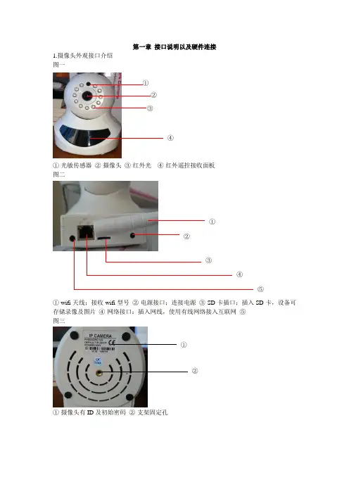
第一章接口说明以及硬件连接1.摄像头外观接口介绍图一①②③④①-光敏传感器②-摄像头③-红外光④-红外遥控接收面板图二①②③④⑤①-wifi天线;接收wifi型号②-电源接口;连接电源③-SD卡插口;插入SD卡,设备可存储录像及图片④-网络接口:插入网线,使用有线网络接入互联网⑤-图三①②①-摄像头有ID及初始密码②-支架固定孔第二章摄像头操作软件下载及安装1、登陆www.2cu.co下载最新版本的摄像头操作系统2、使用手机二维码扫描功能,直接扫描包装盒上的二维码进行下载。
本机以安卓4.22系统下的UC浏览器为例1、打开UC浏览器,点击屏幕左上方的二维码扫描功能(红框处)2、出现以下图示后,将扫描区对准Android的二维码。
3、扫面二维码后出现以下画面,点击本地下载。
4、下载完成安装软件后,第一次运行会出现以下画面(图1)。
点击新用户注册出现(图2)画面,这里先选择“用手机注册”,点击下一步,出现(图3)画面。
输入常用手机号码,点击下一步,网络系统会发送一条注册码信息至注册手机中(图4)。
在(图5)画面中输入验证码,点击下一步,在(图6)画面中输入登录软件密码,点击注册,并完成注册过程,进入软件(图7)图1 图2 图3图4图5 图6 图75、邮箱注册。
第一步点击新用户注册,出现(图2)画面,选择“用邮箱注册”,点击下一步,出现(图3)画面,输入常有邮箱及登录软件密码,点击注册,并完成注册过程,进入软件(图4)。
图1 图4 图2图3第三章网络连接及添加设备一、有线连接1、将已连入局域网中的网线插入摄像头网络线接口2、打开手机操作软件,选择工具箱,点击“摇一摇”后轻轻晃动手机,系统将自动搜索已接入局域网内的摄像头,并点击方框,添加设备。
3、点击添加设备方框后出现下列图示,这里输入摄像头名称及设备密码。
当摇出的设备是新出厂(为设置过密码)时,输入的密码将作为设备访问密码。
输入完毕后,点击右上方的“保存”设备将添加至软件设备列表中。
TI方案H.264 P2P网络摄像机第一章接口说明以及硬件连接第二章局域网登录及P2P网站远程登录观看第三章局域网单机功能设置3.1预置位设置3.2色彩设置/图像镜像/图像翻转3.3WIFI无线设置3.4卡录像设置3.5视频配置3.6音频配置3.7网络配置3.8摄像机密码设置3.9移动侦测设置3.10日期/语言设置第四章安装电脑客户端CMS4.1添加局域网设备4.2添加广域网设备4.3本地电脑录像设置4.4录像回放(回放本地电脑内录像文件/回放卡内录像文件)4.5 CMS软件密码设置/CMS软件语言设置第五章安装手机客户端(安卓免费安装/苹果收费下载)第六章:全国主要省市电信DNS列表参考第一章: 接口说明以及硬件连接第一步将电源适配器与网络摄像机DC 电源口连接.小心: 请务必使用高品质电源.否则很可能损坏IPCAM.第二步将网络电缆一端与网络摄像机RJ45口连接,另一端插入路由器RJ45口.无线设置完毕后再将网线拔掉.机器守望位设计:机器上电自检旋转停留的位置是上次断电时停留过30秒以上的位置。
第三步TF卡请断电时插拔,新卡先格式化.第四步无线天线连接端子.内置麦克风,外接耳机接口.外接报警接口.①报警输出②地③报警5V输出第二章: 局域网登录及P2P网站远程登录观看2.1局域网登录1.使用与摄像机同一个局域网内的电脑2. 安装光盘里的IP 搜索器3. 双击打开IP搜索器4. 网段为192.168.1.1,直接点WEB访问5. 其它网段先修改摄像机IP和默认网关与路由器同步修改IP步骤如下:5.1. 选中IP5.2. 修改IP和网关与路由器同步(在下图2的红色框内修改)例如路由器地址为192.168.0.1,修改摄像机IP地址为192.168.0.10,子网掩码不变,默认网关为192.168.0.15.3. 点“修改网络参数”保存5.4. 摄像机重启大约几秒钟后,重新启动后点“搜索设备”搜索到修改后IP.并访问设备6. 进入摄像机界面第一次登陆界面遇到的IE拦阻如下图(没有文字出现)修改IE安全等级,(IE工具--internet选项--安全--自定义级别)启用ActiveX控件和插件类目下带有ActiveX控件的所有项不能禁用.如下图所示:重新打开IP地址,提示安装插件,安装成功后如下:出厂默认管理者用户名:admin 密码:无登陆成功后,会弹出如图的码流控制对话框,可以选择预览画面时使用主码流或辅码流,也可以通过监视画面左侧的按钮实现。

P2PCAMLIVE 操作手册目录1.前言概述 (3)2.操作环境最低规格 (3)3.摄像机硬体规格 (3)4.支持语系 (3)5.软件操作说明 (4)5.1 画面显示区域 (4)5.2 主要功能区域 (5)5.3 视窗切换区域 (8)5.4 设备列表 (8)1.前言概述基于全球网络架设已逐渐完善,网络摄像机应用的范围也越来越广泛,运用情境小至家庭,透过网络摄像机随时注意家中老人与小孩居家安全,或是在外出时作为监控使用。
大至各类公司、企业,透过网络摄像机进行安全监控等。
故为方便客户使用及有效服务,特开放此P2PCAMLIVE 电脑端监控管理系统,方便使用者除可运用手机APP线上观看摄像机画面外,也可通过个人电脑端进行画面监控与录制,以利于发挥网络摄像机最高效益。
2.操作环境最低规格●支持处理器为Intel® Core™ i3-4005U Processor (3M Cache, 1.80 GHz)以上●支持存储空间需2GB以上●支持操作系统:W indows XP 32bitW indows7 32bit、64bitW indows8 32bit、64bit3.网络摄像机硬体规格●声音格式Pcm:16-bit,8KHzIMA AdpcmSpeex●影像格式H.264Mpeg4Motion Jpeg●影像解析度320*180640*3601280*7204.支持语系目前P2PCAMLIVE提供以下语系,供推广使用:●繁体中文●简体中文●英文日本语5.软件功能规格下图为P2PCAMLIVE 的软件画面,我们将针对上述4大功能做详细说明:5.1 画面显示区:5.1 画面显示区5.2 主要功能区5.3 视窗切换区5.4 设备列表区ABC DE FGA 提供摄像机资讯:包括分辨率、状态及连接人数、连接状态、帧率和码率等。
B 提供手动即时录像功能。
但如果以设置排程或全时录像,除非取消该功能,否则无法手动进行画面录制。

ImagineWorldClient网络视频服务器集中管理软件说明书(修订版-1)目录1、ImagineWorldClient 功能 02、安装ImagineWorldClient 03、启动ImagineWorldClient (1)3.1顶部工具栏 (3)3.2顶部菜单栏 (3)3.3左侧工具栏 (3)3.4视频区 (4)3.5底部工具栏 (5)4菜单操作及鼠标操作 (6)4.1文件 (6)4.2操作 (6)4.3设置 (6)4.4帮助 (7)4.5鼠标操作 (8)5实时视频显示及控制 (8)5.1 实时视频显示画面控制 (8)5.1.1 显示模式切换 (8)5.1.2 单画面显示 (8)5.1.3 全屏显示 (9)5.1.4 轮巡监视 (9)5.2 云台控制 (10)5.3分配摄像机 (11)6本地检索及录像回放 (14)6.1录像检索 (14)6.2文件下载 (15)6.3录像回放 (16)7报警处理 (16)8音频监听及对讲 (16)9电子地图 (17)9.1创建电子地图 (17)9.2报警联动与电子地图 (18)10客户端系统参数设置 (19)10.1系统参数 (19)10.2系统用户 (20)10.3文件服务 (20)10.4转发服务器设置 (21)10.5录像硬盘管理 (21)10.6软件设置 (22)10.7本地联动 (22)10.8其他设置 (23)11视频服务器配置参数设置 (23)11.1设备参数设置 (24)11.1.1基本参数 (24)11.1.2网络参数 (24)11.1.3无线网络 (25)11.1.4系统用户 (25)11.1.5保存-重启-升级 (26)11.2通道参数设置 (26)11.2.1压缩参数 (27)11.2.2移动侦测 (27)11.2.3 OSD叠加 (28)11.2.4设备录像计划 (29)11.2.5视频参数调节 (29)11.2.6图像区域屏蔽 (29)11.2.7图像遮挡检测 (30)11.2.8视频丢失检测 (30)11.2.9JPEG抓拍参数 (31)11.3云台参数设置 (31)11.4报警探头参数设置 (32)11.5设备硬盘 (33)ImagineWorldClient 网络视频服务器软件是一套完整的网络监控管理软件,可以独立运行,可以管理所有配置的视频服务器,可以监视图像,控制云台等。

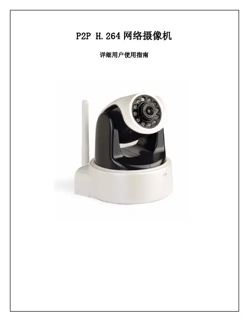
P2P H.264网络摄像机 详细用户使用指南目录第一章 产品介绍 (1)第二章安装 (2)第三章 搜索设备并登陆 (3)第四章视频属性设置和云台控制操作 (4)第五章 系统设置选项 (5)第六章 报警设置 (6)第七章 前段录像 (6)第八章 控制面板 (7)第九章诊断工具 (8)第十章 注销 (9)第十一章 通过广域网访问网络摄像机 (10)第十二章 通过手机访问网络摄像机 (11)第一章产品介绍IPCAM 是一种通过网络传输动态视频的设备,它可以将本地的动态视频通过网络传输到世界各地有网络连接的地方,通过互联网,用户可以随时看到想监控的地方,拓展了人类的视野范围。
IPCAM 的视频传输基于TCP/IP协议. 内置Web服务器支持Inertnet Explore,用户可以通过Web页面管理和维护您的设备,实现远程配置,启动和升级固件。
P2P协议的使用减少了用户设置路由器的过程,插上网线,在客户端软件上输入摄像机的UID即可看到图像,真正做到即插即用。
您可以使用IPCAM监控家庭,办公室,工厂,连锁店,幼儿园等需要监控的场合,通过网络监控,可以对想监控的地方一览无余,在时间和空间上都大大方便了用户。
1.1系统配置需求:在电脑上观看网络摄像机的图像,您的机器需要的最低配置:1.奔四以上CPU,2GHz或更高主频;2.至少有1内存;3.windows xp,windows7操作系统,安装internet explorer 6.0以上浏览器,建议使用internet explorer 8.0观看。
1.2产品特征:安装简易:网络摄像机安装非常简单,不需要专业的布线,只需要电源和网络络连接,如果是采用WIFI无线连接,则只需要提供电源即可,此设备支持WPS功能,用户可以通过WPS 按键和带WPS功能的无线路由器进行连接而不需要密码设置的过程。
P2P协议的使用,可以减少用户设置路由器的麻烦,做到即插即用。
Quick Start Guide: Adding NVRs,DVRs and IP Cameras through P2P[This note applies to all NVRs, DVR and IP Cameras with P2P Services].OverviewThis document reviews the ‘P2P’ (Peer to Peer) service and how to add cameras to easy access and control. The P2P ability provides an easy way for remotely accessing your devices without the need to configure a router or modem. Before starting, be sure to plug in your device to an existing network that has full internet access. Follow the instructions below to start registering your devices through our P2P server!GuideStep 1– First, navigate on a personal computer to . Click on the ‘Sign Up’ option to create a free account on our P2P server. Once done, you will have access to add your DVR, NVR or IP cameras to your account.∙Step 2 –Once logged in, you can simply click the ‘Add’ button towards the left side so to add your device to your account. Simply input a unique ‘Device Name’,‘Serial Number’ (‘SN’) and the ‘Device User’ (use ‘admin’ by default) and ‘Password’ (use ‘admin’ by default). Note that the serial number can be found on the bottom of the unit, the boxing or through its network connection. If the device in question is connected to your network and has internet access, you should see the newly added device on your list. If the s tatus indicates ‘Online’, you may click on the ‘Play’ arrow () to launch the web interface to control it.∙Step 3– You may also a ccess your NVR or DVRs ‘Main Menu’ →‘Settings’ →‘Network’ →’P2P Settings’ (P2P) section. There you should see a ‘Enable’ option and a QR code bar. Make sure you enable the option first and use the mobile application (ICVIEW, ICRSS Pro or other ICRealtime mobile applications) to scan the QR code.Make sure on the mobile application when adding a new device, your ‘register mode’ is set on P2P. Fill in the rest of the information as you did from the first step and you should be able to immediately stream channels from the recorders.∙Step 4– For IP Cameras, you obtain the same QR code to register it but through its web service. Use the serial number to add it to your account or once you have it attached to your network, open a web browser and type in the default IP address such as ‘http://192.168.1.108’. If having trouble finding it on your network use our ‘IP Auto Search’ tool (download from our support website /support). Once you login to the web service of the camera, navigat e to ‘Network’ → ‘TCP/IP’ and click on ‘P2P’. You should find the same menu page as our recorders where you can enable P2P and scan your QR in to your phone for direct access.∙Step 5–Lastly, you may use our SmartICRSS client on your PC or Mac to import all registered devices from . If you have not done so already, visit our support site at /support and download the latest version of SmartICRSS. Once installed, the ‘Devices’ menu from the ‘Home Page’. You should see an ‘Import’ option at the bottom. Click this and choose the ‘MyEasyIP’ tab. Simply input the e-mail address you signed up with and password that goes along with it. Click ‘Import’ after this and if successful, it will import all registered devices prior to signing up. Go to ‘Live View’ from the ‘Home Page’ to login and stream the cameras/recorders.For detailed instructions visit support or the forumIC Realtime LLC3050 N Andrews Avenue ExtensionPompano Beach, FL 33064(866) 997-9009Designs and specifications subject to change without notice. Copyright © 2015 IC Realtime, LLC. All rights reserved.。
网络高清摄像机操作手册法律声明版权所有©杭州海康威视数字技术股份有限公司2021。
保留一切权利。
本手册的任何部分,包括文字、图片、图形等均归属于杭州海康威视数字技术股份有限公司或其关联公司(以下简称“海康威视”)。
未经书面许可,任何单位或个人不得以任何方式摘录、复制、翻译、修改本手册的全部或部分。
除非另有约定,海康威视不对本手册提供任何明示或默示的声明或保证。
关于本产品本手册描述的产品仅供中国大陆地区销售和使用。
本产品只能在购买地所在国家或地区享受售后服务及维保方案。
关于本手册本手册仅作为相关产品的指导说明,可能与实际产品存在差异,请以实物为准。
因产品版本升级或其他需要,海康威视可能对本手册进行更新,如您需要最新版手册,请您登录海康威视官网查阅()。
海康威视建议您在专业人员的指导下使用本手册。
商标声明●为海康威视的注册商标。
●本手册涉及的其他商标由其所有人各自拥有。
责任声明●在法律允许的最大范围内,本手册以及所描述的产品(包含其硬件、软件、固件等)均“按照现状”提供,可能存在瑕疵或错误。
海康威视不提供任何形式的明示或默示保证,包括但不限于适销性、质量满意度、适合特定目的等保证;亦不对使用本手册或使用海康威视产品导致的任何特殊、附带、偶然或间接的损害进行赔偿,包括但不限于商业利润损失、系统故障、数据或文档丢失产生的损失。
●您知悉互联网的开放性特点,您将产品接入互联网可能存在网络攻击、黑客攻击、病毒感染等风险,海康威视不对因此造成的产品工作异常、信息泄露等问题承担责任,但海康威视将及时为您提供产品相关技术支持。
●使用本产品时,请您严格遵循适用的法律法规,避免侵犯第三方权利,包括但不限于公开权、知识产权、数据权利或其他隐私权。
您亦不得将本产品用于大规模杀伤性武器、生化武器、核爆炸或任何不安全的核能利用或侵犯人权的用途。
●如本手册内容与适用的法律相冲突,则以法律规定为准。
本节内容的目的是确保用户通过本手册能够正确使用产品,以避免操作中的危险或财产损失。
P2P网络摄像机操作技术篇你可能会毫不犹豫的告诉我:满街跑的全是P2P网络摄像机!!!凡是家用民用市场用的网络摄像机就是P2P网络摄像机?不是枪机形状的网络摄像机就是P2P网络摄像机?直板机娃娃云台机这种外壳的就是P2P网络摄像机?1 某厂家的总工程师和老板不屑的告诉我:我们只生产P2P 网络摄像机.我自己说是P2P网络摄像机,并且在这个行业中,人人都说我的这些外壳机器就是P2P网络摄像机? -----------你有什么资格说我不是P2P网络摄像机?(该厂家):我的P2P网络摄像机,是PNP的,即插即用的,你的有我简单吗?-------------不知道天有多高,地有多厚?他不知道天外还有天!-------------像其他厂商一样,该厂家的网络摄像机不是即插即用的, 是一个惊天的骗局(***)P2P网络摄像机的说明书是这样写的:/DownLoad.aspx每台机器在出厂时,都写有一个独立的域名解析地址,比如这一台为:udrf.easyn.hk通过远程监控网络摄像机:每次必须登陆摄像机的域名解析服务器,他出厂时已经帮用户设定好了ADMIN 116.24.25.220 就是域名解析服务器的地址,这样的服务器,普顺达在全球据说建了很多台,每台域名解析服务器所管理的摄像机数量是有限的,由于网络环境不一样,需要在全球假设N台服务器,很多人叫服务器群有很多客户反映,在很多种情况下,客户远程基本连接不上,或经常掉线!-----------这就是DDNS解析的重大问题。
普顺达及其他厂家就对客户说:连不上,那我们就在全球架设很多服务器群,让用户买的放心!DDNS解析的不稳定,或中断服务,不是你把服务器架在香港,还是架在海外,还是架N台服务器所能解决的。
我们不能说(某厂家)的服务态度不好,完全是DDNS域名解析技术所决定的.--------我要请问该厂家的工程师,我在外网监控的话,我怎么能记住我的摄像机的域名解析地址?最让用户不可理解的是:同一局域网放置两台网络摄像机,不修改路由器的端口映射,永远看不到视频监控.该厂家对外宣传说:这就是P2P网络摄像机!!!!不需要第三方域名解析服务器(花生壳),自己建立域名解析服务器群,就是P2P 网络摄像机. SO EASY!这句广告词就是放屁!全世界所有的流媒体协议的网络摄像机,如要实现远程监控,-----------必须经过DDNS域名解析,放置两台必需对路由器进行端口映射的设置。
Operating InstructionsNetwork CameraModel No. WV-SW390 SeriesWV-SC380 SeriesWV-SW170 SeriesWV-ST160 SeriesWV-SW396WV-SW175This manual covers the models: WV-SW390 Series (WV-SW396, WV-SW395, WV-SW396E, WV-SW395E,WV-SW395R, WV-SW395PJ), WV-SC380 Series (WV-SC386, WV-SC385, WV-SC384, WV-SC386E,WV-SC385E, WV-SC384E, WV-SC385R, WV-SC384R, WV-SC385PJ), WV-SW170 Series (WV-SW175,WV-SW174W, WV-SW172, WV-SW175E, WV-SW174WE, WV-SW172E), and WV-ST160 Series (WV-ST165, WV-ST162, WV-ST165E, WV-ST162E).Before attempting to connect or operate this product, please read these instructionscarefully and save this manual for future use.The model number is abbreviated in some descriptions in this manual.WV-SW395R, WV-SC385R, and WV-SC384R do not support the HTTPS function.PrefacePrefaceAbout the user manualsThere are 2 sets of operating instructions for the WV-SW396, WV-SW395, WV-SC386, WV-SC385,WV-SC384, WV-SW395PJ, WV-SC385PJ, WV-SW175, WV-SW174W, WV-SW172, WV-ST165, WV-ST162 (P model), WV-SW396E, WV-SW395E, WV-SC386E, WV-SC385E, WV-SC384E, WV-SW395R,WV-SC385R, WV-SC384R, WV-SW175E, WV-SW174WE, WV-SW172E, WV-ST165E, WV-ST162E (E model) as follows.•Installation Guide: Explains how to install and connect devices.When you use the WV-SW396/WV-SW396E or WV-SW395/WV-SW395E/WV-SW395PJ, refer toWV-SW396/WV-SW395/WV-SW396E/WV-SW395E/WV-SW395PJ Installation Guide.When you use the WV-SW395R, refer to WV-SW395R Installation Guide.When you use the WV-SC386/WV-SC386E, refer to WV-SC386/WV-SC386E Installation Guide.When you use the WV-SC385/WV-SC385E/WV-SC385PJ or WV-SC384/WV-SC384E, refer toWV-SC385/WV-SC384/WV-SC385E/WV-SC384E/WV-SC385PJ Installation Guide.When you use the WV-SC385R/WV-SC384R, refer to WV-SC385R/WV-SC384R Installation Guide.When you use the WV-SW175/WV-SW175E or WV-SW172/WV-SW172E, refer to WV-SW175/WV-SW172/WV-SW175E/WV-SW172E Installation Guide.When you use the WV-SW174W/WV-SW174WE, refer to WV-SW174W/WV-SW174WE InstallationGuide.When you use the WV-ST165/WV-ST165E or WV-ST162/WV-ST162E, refer to WV-ST165/WV-ST162/ WV-ST165E/WV-ST162E Installation Guide.•Operating Instructions: Explains how to perform the settings and how to operate this camera. This Operating Instructions covers the models: WV-SW396, WV-SW395, WV-SC386, WV-SC385, WV-SC384, WV-SW396E, WV-SW395E, WV-SC386E, WV-SC385E, WV-SC384E, WV-SW395R, WV-SC385R,WV-SC384R, WV-SW395PJ, WV-SC385PJ, WV-SW175, WV-SW174W, WV-SW172, WV-ST165,WV-ST162, WV-SW175E, WV-SW174WE, WV-SW172E, WV-ST165E, WV-ST162E.The model number is abbreviated in some descriptions in this manual.The screens used in these operating instructions show the case of WV-SW396 (P model). Depending on the model used, the screens shown in the explanations may differ to the actual camera screens.The model numbers are abbreviated in the following manner in some descriptions in this manual.Model number Abbreviation Model number Abbreviation WV-SW396SW396WV-SW395SW395WV-SC386SC386WV-SC385SC385WV-SC384SC384WV-SW175SW175WV-SW174W SW174W WV-SW172SW172WV-ST165ST165WV-ST162ST162About notationsThe following notations are used when describing the functions limited for specified models.The functions without the notations are supported by all models.*Notation Model Notation ModelSW396WV-SW396SW395WV-SW3952Operating InstructionsPrefaceNotation Model Notation ModelSC386WV-SC386SC385WV-SC385SC384WV-SC384SW175WV-SW175SW174W WV-SW174W SW172WV-SW172ST165WV-ST165ST162WV-ST162*Except for the HTTPS function for WV-SW395R, WV-SC385R, and WV-SC384R.Trademarks and registered trademarks•Microsoft, Windows, Windows Vista, Windows Media, Internet Explorer, ActiveX and DirectX are either registered trademarks or trademarks of Microsoft Corporation in the United States and/or other countries.•Microsoft product screen shot(s) reprinted with permission from Microsoft Corporation.•iPad, iPhone, iPod touch, and QuickTime are trademarks of Apple Inc., registered in the U.S. and other countries.•Android is a trademark of Google Inc. Use of this trademark is subject to Google Permissions.•SDHC Logo is a trademark of SD-3C, LLC.•All other trademarks identified herein are the property of their respective owners.AbbreviationsThe following abbreviations are used in these operating instructions.Microsoft® Windows® 7 is described as Windows 7.Microsoft® Windows Vista® is described as Windows Vista.Microsoft® Windows® XP SP3 is described as Windows XP.Windows® Internet Explorer® 9.0, Windows® Internet Explorer® 8.0, Windows® Internet Explorer® 7.0 and Microsoft® Internet Explorer® 6.0 are described as Internet Explorer.SDHC/SD memory card is described as SD card or SD memory card.Universal Plug and Play is described as UPnP™ or UPnP.Operating Instructions3Viewer softwareIt is necessary to install the viewer software “Network Camera View 4S” to display images on a PC. This software can be installed directly from the camera or by selecting the [Install] button next to [ViewerSoftware] on the menu of the CD-ROM provided, and then following the on-screen instructions.IMPORTANT•The default setting of “Automatic installation of viewer software” is “On”. Follow the instructions on page 241 when the message is displayed on the information bar of the browser.•When the “Live” page is displayed for the first time, the install wizard of the ActiveX ® control required to display images from the camera will be displayed. Follow the instructions of the wizard.•When the install wizard is displayed again even after completing the installation of the ActiveX, restart the PC.•The viewer software used on each PC should be licensed individually. The number of installations ofthe viewer software from the camera can be checked on the [Upgrade] tab of the “Maintenance” page (®page 217). Refer to your dealer for the software licensing.4Operating InstructionsPrefaceTable of Contents Table of Contents1Monitor images on a PC (9)1.1Monitor images from a single camera (9)1.2About the “Live” page (12)1.3Monitor images from multiple cameras (19)2Monitor images on a cellular phone/mobile terminal (20)2.1Monitor images on a cellular phone (20)2.2Monitor images on a mobile terminal (23)3Record images on the SD memory card manually (SW396/SW395/ SC386/SC385/SC384/SW175/SW172/ST165/ST162) (31)4Action at an alarm occurrence (33)4.1Alarm type (33)4.2Action at an alarm occurrence (33)5Transmit images onto an FTP server (35)5.1Transmit an alarm image at an alarm occurrence (Alarm imagetransmission) (35)5.2Transmit images at a designated interval or period (FTP periodic imagetransmission) (35)5.3Save images on the SD memory card when images fail to transmit using the FTPperiodic image transmission function (SW396/SW395/SC386/SC385/SC384/SW175/SW172/ST165/ST162) (36)6Display the log list (SW396/SW395/SC386/SC385/SC384/SW175/ SW172/ST165/ST162) (37)7Playback of images on the SD memory card (SW396/SW395/SC386/ SC385/SC384/SW175/SW172/ST165/ST162) (41)7.1About the playback page (42)7.2Download the images (When “H.264” is selected for “Recording format” of the SDmemory card) (44)8About the network security (46)8.1Equipped security functions (46)9Display the setup menu from a PC (47)9.1How to display the setup menu (47)9.2How to operate the setup menu (49)9.3About the setup menu window (51)10Configure the basic settings of the camera [Basic] (53)10.1Configure the basic settings [Basic] (53)10.2Configure the settings relating to the SD memory card [SD memory card] (SW396/SW395/SC386/SC385/SC384/SW175/SW172/ST165/ST162) (58)10.3Access copy images saved on the SD memory card onto the PC [SD memory cardimages] (SW396/SW395/SC386/SC385/SC384/SW175/SW172/ST165/ST162) (65)10.4Configure the settings relating to the logs [Log] (SW396/SW395/SC386/SC385/SC384/SW175/SW172/ST165/ST162) (73)10.4.1How the logs and images are saved depending on the settings for “Alarm” (75)Operating Instructions5Table of Contents10.4.2How the logs and images are saved depending on the settings for “Manual/Schedule” (76)10.4.3How the logs and images are saved depending on the settings for “FTP error” (78)11Configure the settings relating to images and audio [Image/ Audio] (79)11.1Configure the settings relating to the aspect ratio [JPEG/H.264] (79)11.2Configure the settings relating to JPEG images [JPEG/H.264] (or [JPEG/MPEG-4]) (80)11.3Configure the settings relating to H.264 images [JPEG/H.264] (82)11.4Configure the settings relating to MPEG-4 images [JPEG/MPEG-4] (SW396/SW395/SC386/SC385/SC384) (88)11.5Configure the settings relating to the camera operations [Cam. Function] (94)11.6Configure the settings relating to images and the preset positions [Image/Position] (98)11.6.1Configure the settings relating to image quality (“Image adjust” setup menu) (SW396/SW395/SC386/SC385) (99)11.6.2Configure the settings relating to image quality (“Image adjust” setup menu) (SC384/SW175/SW174W/SW172/ST165/ST162) (106)11.6.3Set mask areas (111)11.6.4Configure the settings relating to the preset positions (“Preset position” setupmenu) (113)11.6.4.1Register the preset positions (115)11.6.5Configure the settings relating to the auto pan function (“Auto pan” setup menu) (SW396/SW395/SC386/SC385/SC384) (117)11.6.6Configure the settings relating to patrol (“Patrol” setup menu) (SW396/SC386) (118)11.6.7Configure the settings relating to auto track (“Auto track” setup menu) (SW396/SC386) (120)11.6.8Configure the settings relating to direction (“Direction” setup menu) (SW396/SC386) (126)11.6.9Configure the settings relating to the privacy zone (“Privacy zone” setup menu) (127)11.7Configure the settings relating to audio [Audio] (129)12Configure the multi-screen settings [Multi-screen] (132)13Configure the alarm settings [Alarm] (134)13.1Configure the settings relating to the alarm action [Alarm] (134)13.2Configure the settings relating to the camera action on alarm occurrence[Alarm] (136)13.2.1Configure the settings relating to Preset per sender (“Preset per sender” setup menu)(SW396/SC386) (138)13.3Configure the settings relating to the alarm image [Alarm] (138)13.4Configure the settings relating to H.264 recording [Alarm] (SW396/SW395/SC386/SC385/SC384/SW175/SW172/ST165/ST162) (140)13.5Configure the settings relating to the alarm output terminal [Alarm] (141)13.6Change the AUX name [Alarm] (142)13.7Configure the VMD settings [VMD area] (143)13.8Configuration of the settings relating to the mail notification [Notification] (147)13.9Configure the settings relating to Panasonic alarm protocol [Notification] (148)14Configure the setting relating to the image recognition [Advanced func.] (152)14.1Configure the settings relating to the XML notification [XML notification] (152)14.2Configuration of the settings relating to the face detection [Face detection] (154)6Operating InstructionsTable of Contents 15Configure the settings relating to the authentication [User mng.] (156)15.1Configure the settings relating to the user authentication [User auth.] (156)15.2Configure the settings relating to the host authentication [Host auth.] (157)15.3Configure the settings relating to the priority stream [System] (158)16Configure the settings of the servers [Server] (161)16.1Configure the settings relating to the mail server [Mail] (161)16.2Configure the settings relating to the FTP server [FTP] (162)16.3Configure the settings relating to the NTP server [NTP] (163)17Configuring the network settings [Network] (166)17.1Configure the network settings [Network] (166)17.2Configure the HTTPS settings (174)17.2.1Generation of the CRT key (SSL encryption key) (175)17.2.2Generation of the self-signed certificate (security certificate) (176)17.2.3Generation of CSR (Certificate Signing Request) (178)17.2.4Installation of the server certificate (179)17.2.5Configuration of the connection protocol (180)17.3Access the camera using the HTTPS protocol (181)17.3.1Install the security certificate (181)17.4Configure the settings relating to DDNS [DDNS] (191)17.4.1Configuration of the DDNS service (Example of the “” service) (192)17.4.2When using the “” service (193)17.4.3Procedure to register information for the “” service (194)17.4.4Checking the information registered for the “” service (195)17.4.5When using “Dynamic DNS Update” (195)17.4.6When using “Dynamic DNS Update(DHCP)” (196)17.5Configure the settings relating to SNMP [SNMP] (196)17.6Configure the settings relating to the FTP periodic image transmission [FTP img.trans.] (197)17.7Configure the schedule settings of the FTP periodic image transmission [FTP img.trans.] (199)17.7.1How to set the schedules (200)17.7.2How to delete the set schedule (201)18Use the camera on a wireless LAN [Wireless] (SW174W only) (202)18.1Manually connecting the camera to a wireless LAN (manual settings)[Basic] (202)18.2Connecting the camera to a wireless LAN with WPS (automatic settings)[Basic] (206)18.3Using the camera's Wireless QoS [Basic] (210)18.4Confirming the camera's wireless information [Status] (210)19Configure the settings relating to the schedules [Schedule] (213)20Maintenance of the camera [Maintenance] (216)20.1Check the system log [System log] (216)20.2Upgrade the firmware [Upgrade] (217)20.3Check the status [Status] (218)20.4Reset the settings/Reboot the camera [Default reset] (220)21Using the CD-ROM (222)21.1About the CD launcher (222)Operating Instructions7Table of Contents21.2Installing Panasonic “IP Setting Software” (223)21.3Installing the manuals (224)21.4Installing the Viewer software (224)21.5Configure the network settings of the camera using the Panasonic “IP SettingSoftware” (225)22About the displayed system log (227)23Troubleshooting (231)24Directory structure of drive B (SW396/SW395/SC386/SC385/SC384/ SW175/SW172/ST165/ST162) (243)8Operating Instructions1 Monitor images on a PCThe following are descriptions of how to monitor images from the camera on a PC.1.1 Monitor images from a single cameraNote•SW175/SW174W/SW172/ST165/ST162 do not support MPEG-4.1.Start up the web browser.2.Enter the IP address designated using the Panasonic “IP Setting Software” in the address box of thebrowser.•Example when entering an IPv4 address: http://URL registered using IPv4 addresshttp://192.168.0.10/•Example when entering an IPv6 address: http://[URL registered using IPv6 address]http://[2001:db8::10]/<Example of IPv4 access><Example of IPv6 access>IMPORTANT•When the HTTP port number is changed from “80”, enter “http://IP address of the camera + : (colon)+ port number” in the address box of the browser. (Example: http://192.168.0.11:8080)•When the PC is in a local network, configure the proxy server setting of the web browser (under [Internet Options...] under [Tools] of the menu bar) to bypass the proxy server for the local address.Note •Refer to page 181 for further information about the case in which “HTTPS” is selected for“HTTPS” - “Connection” on the [Network] tab of the “Network” page (®page 166).3.Press the [Enter] key on the keyboard.SW396SW395 SC386 SC385 SC384:When “On” is selected for “User auth.”, the authentication window will be displayed before displaying live images. Enter the user name and password. The default user name and password are as er name: admin Password: 12345SW175 SW174W SW172 ST165 ST162:The authentication window will be displayed before displaying live images. Enter the user name and password. The default user name and password are as follows.User name: admin Operating Instructions 91 Monitor images on a PC1 Monitor images on a PCPassword: 12345→The “Live” page will be displayed. Refer to page 12 for further information about the “Live” page.IMPORTANT•To enhance the security, change the password for the user name “admin”. It is recommended to change this password periodically.•When displaying multiple H.264 (or MPEG-4) images on a PC, images may not be displayed depending on the performance of the PC.Note•When “H.264” is selected for “Video encoding format”, H.264 video will be displayed. When “MPEG-4” is selected, MPEG-4 images will be displayed.•The maximum number of concurrent access user is 14 including users who is receiving H.264 (or MPEG-4) images and users who are receiving JPEG images. Depending on the set values for“Bandwidth control(bit rate)” and “Max bit rate (per client)*”, the maximum concurrent access numbermay be 14 or less users. When 14 users are concurrently accessing, the access limit message will bedisplayed for users who subsequently attempt to access. When “Multicast” is selected for“Transmission type” of “H.264” (or “MPEG-4”), only the first user who accessed to monitor H.264 (orMPEG-4) images will be included in the maximum number. The second and subsequent users whoare monitoring H.264 (or MPEG-4) images will not be included in the maximum number.•When “On” is selected for “H.264 transmission” (or “MPEG-4 transmission”) (®page 84, page 90),H.264 (or MPEG-4) images will be displayed. When “Off” is selected, a JPEG image will be displayed.It is possible to display a JPEG image even when “On” is selected for “H.264 transmission” (or“MPEG-4 transmission”).•The refresh interval may become longer depending on a network environment, PC performance, photographic subject, access traffic, etc.<Refresh interval of JPEG images>When “On” is selected for “H.264 transmission” (or “MPEG-4 transmission”)SW395SC385:max. 10 fps (1280x960, 1280x720, 800x600)max. 15 fps (Other image capture sizes)SW396SC386SC384SW175SW174W SW172ST165ST162:10Operating Instructions1 Monitor images on a PCmax. 5 fpsWhen “Off” is selected for “H.264 transmission” (or “MPEG-4 transmission”)max. 30 fps1.2 About the “Live” pageNote•SW175/SW174W/SW172/ST165/ST162 do not support MPEG-4.ACDEF H IJ KGBR T U V W XY S N M O PQ L [select language] pull-down menuThe camera’s display language can be selected. The default language can be set in the [Language] in the[Basic] settings. (®page 53)[Setup] button *1Displays the setup menu. The button will turn green and the setup menu will be displayed.[Live] button Display the “Live” page. The button will turn green and the “Live” page will be displayed.[Multi-screen] buttons Images from multiple cameras can be displayed on a multi-screen by registering cameras on the setup menu. (®page 19)[Compression] buttons•[H.264]/[MPEG-4] button: The letters “H.264” (or “MPEG-4”) on the button will turn green and an H.264 (or MPEG-4) image will be displayed. When “On” is selected for “H.264 transmission” (or“MPEG-4 transmission”) of “H.264(1)”, “H.264(2)” (or “MPEG-4(1)”, “MPEG-4(2)”), the [H.264] (or[MPEG-4]) button will be displayed. (®page 84, page 90)•[JPEG] button: The letters “JPEG” on the button will turn green and JPEG image will be displayed.[Stream] buttonsThese buttons will be displayed only when an H.264 (or MPEG-4) image is displayed.1 Monitor images on a PC1 Monitor images on a PC •[1] button: The letter “1” will turn green and images in the main area will be displayed in accordance with the setting of “H.264(1)” (or “MPEG-4(1)”). (®page 84, page 90)•[2] button: The letter “2” will turn green and images in the main area will be displayed in accordance with the setting of “H.264(2)” (or “MPEG-4(2)”). (®page 84, page 90)[Image capture size] buttonsThese buttons will be displayed only when a JPEG image is displayed.[VGA]The letters “VGA” will turn green and images in the main area will be displayed in VGA size.[QVGA]The letters “QVGA” will turn green and images in the main area will be displayed in QVGA size.[640x360]The letters “640x360” will turn green and images in the main area will bedisplayed in 640 x 360 (pixels).[320x180]The letters “320x180” will turn green and images in the main area will bedisplayed in 320 x 180 (pixels).SW396SW395SC386SC385SC384SW175SW174W ST165:[1280x960]The letters “1280x960” will turn green and images in the main area will bedisplayed in 1280 x 960 (pixels).[1280x720]The letters “1280x720” will turn green and images in the main area will bedisplayed in 1280 x 720 (pixels).SW396SW395SC386SC385SW172ST162:[800x600]The letters “800x600” will turn green and images in the main area will bedisplayed in 800 x 600 (pixels).NoteSW396SW395SC386SC385SC384SW175SW174W ST165:•The buttons [VGA], [QVGA] and [1280x960] are displayed only when “4:3”*2 or “4:3 (VGA)”*3 is selected for “Aspect ratio”.•The buttons [640x360], [320x180] and [1280x720] are displayed only when “16:9” is selected for “Aspect ratio”.•When “1280x960” or “1280x720” is selected for the image capture size, it may become smaller than the actual size depending on the window size of the web browser.SW172ST162:•The buttons [VGA], [QVGA] and [800x600] are displayed only when “4:3” is selected for “Aspect ratio”.•The buttons [640x360] and [320x180] are displayed only when “16:9” is selected for “Aspect ratio”.[Image quality] buttonsThese buttons will be displayed only when a JPEG image is displayed.•[1] button: Images in the main area will be displayed in accordance with the setting for “Quality1” of “Image quality setting”. (®page 80)•[2] button: Images in the main area will be displayed in accordance with the setting for “Quality2” of “Image quality setting”. (®page 80)[AUX] buttons*4These buttons will be displayed only when “AUX output” is selected for “Terminal 3” of “Alarm” on the setup menu. (®page 134)•[Open] button: The letters “Open” on the button will turn green and the status of AUX connector will be open.•[Close] button: The letters “Close” on the button will turn green and the status of the AUX connector will be closed.Note•The names of “AUX”, “Open” and “Close” can be changed. (®page 142)[Rec. on SD] button*4SW396SW395SC386SC385SC384SW175SW172ST165 ST162This button will be displayed only when “Manual” is selected for “Save trigger” on the setup menu.(®page 60)Click this button to manually record images on the SD memory card. Refer to page 31 for descriptionsof how to manually record images on the SD memory card.[Log] button*1SW396SW395SC386SC385SC384SW175SW172ST165ST162[List] button will be displayed only when “On” is selected for “Save logs” on the setup menu.(®page 73)When this button is clicked, the log list will be displayed and images saved on the SD memory card can be played.Refer to page 37 for further information about the log list and for how to play images on the SD memory card.[Zoom] buttons*4•: Click this button to adjust the zoom ratio to the “Wide” side.•: Click this button to set the zoom ratio to x1.0.•: Click this button to adjust the zoom ratio to the “Tele” side.[Focus] buttons*4SW396SW395SC386SC385SC384•: Click this button to adjust the focus automatically.•: Click this button to adjust the focus to the “Near” side.•: Click this button to adjust the focus to the “Far” side.Note•When shooting the following place or the following subjects, focus may not be adjusted automatically. Adjust the focus manually.–Shiny or strongly reflective subject–Subject through the glass with dew or smudge–Two subjects whose distances from the camera are different–Less contrast subject (e.g. white wall)–Horizontal-striped subject such as a window blind–Inclined subject–Dark subject[Auto mode]*4Select an operation from the pull-down menu and click the [Start] button. The selected operation will start.Click the [Stop] button to stop the operation.The selected operation will stop when the camera (panning/tilting/zooming/focusing) is operated or when an action that is to be taken according to the settings for “Self return” (®page 95) or for “Camera action on alarm” (®page 136) starts.•Auto track SW395SC385: Automatically tracks objects in the shooting area.Note•The auto track function works only when the size of the object is larger than 1/300 of the main area and also the contrast ratio between the object and the background is more than 5%.•The auto track function of this camera is the simplified function that tracks a moving object in the shooting area. It may be impossible to track a moving object in the following cases.1 Monitor images on a PC1 Monitor images on a PC–When there are multiple moving objects in the shooting area–When the contrast ratio between a moving object and the background is almost none–When an object moves quickly–When a moving object is too small or too big–When the shooting area is dark–When there is a flicker in the shooting area•When the zoom ratio is set to the “Tele” side, it may be difficult to obtain accuracy with the auto tracking function. It is recommended to use the auto tracking function with setting the zoom ratio to the “Wide” side.•Auto track SW396SC386: Automatically tracks objects in the shooting area.Note•With the Auto track feature, objects moving in the screen are picked out and automatically tracked.•In the following situations, targets may not be able to be tracked, or false detections may occur.–when there is little contrast between the subject and the background–when the dome is dirty or wet–when there are large changes to the lighting intensity–when there are many moving objects other than the subject–when there is a change to the axis of the camera’s lens–when the subject moves directly underneath the camera–when there is harsh flickering–when there are reflections from light entering the dome due to reflections from a window or road, or from a backlight–when the target is hidden behind a utility pole or other objects–when the subject passes by other moving objects–when the target moves too fast or too slow–when the camera is shaking•When the zoom ratio is set to the “Tele” side, it may be difficult to obtain accuracy with the auto tracking function. It is recommended to use the auto tracking function with setting the zoomratio to the “Wide” side.•Auto pan SW396SW395SC386SC385SC384: Automatically pans between the start position and the end position set in advance (®page 117).Even when the camera is operated for zooming or focusing, the camera continues panning.(However, panning will stop when the zoom button (x1) is clicked.)•Preset sequence SW396SW395SC386SC385SC384: Automatically moves to the preset positions (®page 113) orderly (start from the lowest preset position number).•360 map-shot SW396SW395SC386SC385SC384: Moves 45° horizontally at a time and repeats 8 times to shoot images of each 45° position (45° x 8 = 360°), and then displays 8 thumbnail images of each 45° position (45° x 8 = 360°) on a newly opened window. When a thumbnail image is clicked, the camera moves to the respective position and live images will be displayed on the “Live”page.•Preset map-shot: Eight thumbnail images of the preset position 1-8 (®page 113) will be displayed orderly on a newly displayed window. When a thumbnail image is clicked, the camera moves to the respective position and live images will be displayed on the “Live” page.Note•Do not operate the browser until all the thumbnail images are displayed and the camera returns to the original position (where the camera was when “360 map-shot” or “Preset map-shot” was carried out).。
P2P IP CAM监控TI方案第一章接口说明以及硬件连接第二章局域网登录及P2P网站远程登录观看3.1预置位设置3.2色彩设置/图像镜像/图像翻转3.3WIFI无线设置3.4卡录像设置3.5视频配置3.6音频配置3.7网络配置3.13.8摄像机密码设置3.9移动侦测设置3.10日期/语言设置第四章安装电脑客户端CMS4.1添加局域网设备4.2添加广域网设备4.3本地电脑录像设置4.4录像回放(回放本地电脑内录像文件/回放卡内录像文件)4.5 CMS软件密码设置/CMS软件语言设置第五章安装手机客户端(安卓免费安装/苹果收费下载)第六章:全国主要省市电信DNS列表参考第一章: 接口说明以及硬件连接第一步将电源适配器与网络摄像机DC电源口连接.小心:请务必使用高品质电源.否则很可能损坏IPCAM.第二步将网络电缆一端与网络摄像机RJ45口连接,另一端插入路由器RJ45口.无线设置完毕后再将网线拔掉.机器守望位设计:机器上电自检旋转停留的位置是上次断电时停留过30秒以上的位置。
第三步TF卡请断电时插拔,新卡先格式化.第四步无线天线连接端子.内置麦克风,外接耳机接口.外接报警接口.①报警输出②地③报警5V输出第二章: 局域网登录及P2P网站远程登录观看2.1局域网登录1.使用与摄像机同一个局域网内的电脑2. 安装光盘里的IP 搜索器3. 双击打开IP搜索器4. 网段为,直接点WEB访问5. 其它网段先修改摄像机IP和默认网关与路由器同步修改IP步骤如下:5.1. 选中IP5.2. 修改IP和网关与路由器同步(在下图2的红色框内修改)例如路由器地址为,修改摄像机IP地址为,子网掩码不变,默认网关为5.3. 点“修改网络参数”保存5.4. 摄像机重启大约几秒钟后,重新启动后点“搜索设备”搜索到修改后IP.并访问设备6. 进入摄像机界面第一次登陆界面遇到的IE拦阻如下图(没有文字出现)修改IE安全等级,(IE工具--internet选项--安全--自定义级别)启用ActiveX控件和插件类目下带有ActiveX控件的所有项不能禁用.如下图所示:重新打开IP地址,提示安装插件,安装成功后如下:出厂默认管理者用户名:admin 密码:无登陆成功后,会弹出如图的码流控制对话框,可以选择预览画面时使用主码流或辅码流,也可以通过监视画面左侧的按钮实现。
注意FCC 警告红外型网络摄像机经过检测,完全符合FCC规则第15条中关于A类电子设备的规定。
这些限制性规定用于保证设备使用时,在一定程度上,运行不会受外部干扰的影响。
该设备为电磁设备,因此需严格按照本手册说明进行安装和使用,否则有可能对无线电通讯产生干扰。
同时,特定环境下的安装无法保证完全杜绝干扰。
在准备做系统接线或操作之前,请认真阅读本手册,并妥善保管好本手册,以便将来查阅。
重要安全建议与警告:●仔细阅读并妥善保存好本手册;●不要将本产品放置于靠近水源、火源及高强度电磁辐射的地方;●请保持本产品周围良好的通风环境。
●擦拭本产品表面时,请使用干燥、柔软的抹布。
●在长时间不使用本产品时建议拨下电源插头;●本产品只可使用由生产厂家推荐的辅助设备及备件;●请放置好电源及与本产品所连接的所有线缆,注意不可放置于地下或人经常活动的地方;●有关产品维修方面问题,请咨询专业人员,切勿擅自打开外盖进行维修;●请妥善保管好产品包装箱,方便设备的转移或搬运。
标志表示错误操作时,产品内部的非绝缘部件可能产生有害电压。
用户需严格按照标志处的说明进行操作。
警告:为了避免设备受潮导致漏电或起火,请不要将该设备放置在潮湿或露天的地方!第二章IE浏览器设置用户浏览视频图像,需要对显示器或其他视频设备的IE浏览器进行调节,并据界面提示设置相应的系统功能。
设置IE浏览器时必须注意:●该网络摄像机支持的浏览器版本:Internet Explorer 6.0及其以上版本;●必须安装ActiveX控件和支持Directx 9.0c视频图像浏览软件;2.1 设置IE浏览器使用这款网络摄像机时,可以通过IE或HVMS等软件来浏览图像。
当用IE浏览器观看图像时,需要安装ActiveX控件,否则无法正常的浏览视频图像。
要安装控件需要对IE的安全级别进行设置以便正常的下载控件。
1. 单击菜单栏选项中的“工具”,再单击弹出的“Internet选项”。
第一章接口说明以及硬件连接
1.摄像头外观接口介绍
图一
①
②
③
④
①-光敏传感器②-摄像头③-红外光④-红外遥控接收面板
图二
①
②
③
④
⑤
①-wifi天线;接收wifi型号②-电源接口;连接电源③-SD卡插口;插入SD卡,设备可存储录像及图片④-网络接口:插入网线,使用有线网络接入互联网⑤-
图三
①
②
①-摄像头有ID及初始密码②-支架固定孔
第二章摄像头操作软件下载及安装
1、登陆www.2cu.co下载最新版本的摄像头操作系统
2、使用手机二维码扫描功能,直接扫描包装盒上的二维码进行下载。
本机以安卓4.22系统下的UC浏览器为例
1、打开UC浏览器,点击屏幕左上方的二维码扫描功能(红框处)
2、出现以下图示后,将扫描区对准Android的二维码。
3、扫面二维码后出现以下画面,点击本地下载。
4、下载完成安装软件后,第一次运行会出现以下画面(图1)。
点击新用户注册出现(图2)画面,这里先选择“用手机注册”,点击下一步,出现(图3)画面。
输入常用手机号码,点击下一步,网络系统会发送一条注册码信息至注册手机中(图4)。
在(图5)画面中输入验证码,点击下一步,在(图6)画面中输入登录软件密码,点击注册,并完成注册过程,进入软件(图7)
图1 图2 图3
图4
图5 图6 图7
5、邮箱注册。
第一步点击新用户注册,出现(图2)画面,选择“用邮箱注册”,点击下一步,出现(图3)画面,输入常有邮箱及登录软件密码,点击注册,并完成注册过程,进入软件(图4)。
图1 图4 图2
图3
第三章网络连接及添加设备
一、有线连接
1、将已连入局域网中的网线插入摄像头网络线接口
2、打开手机操作软件,选择工具箱,点击“摇一摇”后轻轻晃动手机,系统将自动搜索已接入局域网内的摄像头,并点击方框,添加设备。
3、点击添加设备方框后出现下列图示,这里输入摄像头名称及设备密码。
当摇出的设备是新出厂(为设置过密码)时,输入的密码将作为设备访问密码。
输入完毕后,点击右上方的“保存”设备将添加至软件设备列表中。
二、无线连接
在没有网线连接的情况下,可选用红外遥控小配件配置摄像头连入无线WIFI。
操作步骤如下:
1、将红外线装置插入手机耳机孔
2、打开摄像头手机操作软件,选择工具箱,再选择红外遥控。
3、之后进入如下界面,将插在手机上的红外线装置对准摄像头的茶色面板,按下屏幕中的上下左右测试是否有效,当看到摄像头旋转说明遥控器已经能正常控制设备。
4、点击设置wifi,在右侧的wifi列表中点击将要使用的wifi热点,在弹出的对话框中输入wifi密码及摄像头的设备密码(新设备密码为空,设备密码地方不用填写)。
输入无误后点击设置按钮,当听到设备发出声响时,表示设置成功,设备已接入网络中。
5、进入工具箱,点击“摇一摇”后轻轻晃动手机,系统将自动搜索接入网络中的设备,添加设备步骤同有线连接,此处不再赘述。
三、通过设备ID进行连接
摄像头设备已接入网络,且工作正常的状态下,可直接输入设备ID及密码添加设备。
点击拨号功能(图1),输入已知的设备ID,点击呼出键,在弹出的对话框中输入设备密码即可(图2)。
图2 图1
第四章摄像头的使用及操作
一、基本功能及操作
1、添加设备完成后,可通过摄像头全方位观察周围环境。
打开手机操作软件,选择设备列表,可以看见当前已添加的设备(图1),点击列表中的设备即可进入观察视角(图2),用手指轻轻滑动屏幕即可旋转摄像头观察角度,调整角度可上下左右调节。
2、在通过摄像机观察周围环境时,画面清晰度有“高清”、“标清”、“流畅”三种格式可选,可根据实际情况选择,清晰度越高对网络质量要求越高。
3、屏幕下方工具栏介绍。
静音键,点击该按键,将不在播放摄像头周围的声音情况,再次点击将恢复播放摄像头周围声音。
截图键,点击该按键,将当前画面截图保存,可在工具箱的查看截图查看截取的画面。
挂断键,点击该按键,结束当前监视画面。
对讲键,需要将声音传送至摄像头扬声器时,长按该按键,开始说话,松开按键即结束通话。
二、摄像头功能设置
1、点击设备列表的空白处(图一红框区域),在出现的对话框中点击“设置”进入设置功能。
①时间设置。
点击时间设置,调整好正确时间后点击应用,完成设置。
②媒体设置。
点击媒体设置,此处可根据需要选择摄像头录像视频的制式和音量大小。
③安全设置。
点击安全设置,该设置可以重新设置设备登录密码,更改密码前需先正确输入设备旧密码后在输入新密码,完成后点击屏幕右上方的保存按键,完成密码更改。
④网络设置。
点击网络设置,该设置可将设备连接方式更改为“有线”或“WiFi”,及更改无线网络连接热点。
“有线”方式必须在有网线连接的情况下才能正常传输图像声音,“WiFi”则是在接入的网络中wifi覆盖的范围内都能正常传输图像声音,不需要接入网线。
⑤报警设置。
本摄像头产品具有移动侦测及门磁报警功能(详细参见防区设置),首先点击进入报警设置功能,报警推送账号默认设定为本机注册时所获得的账号,也可以根据需求添加其他账号(最多能添加3个),可以实现设备报警后推送至其他安装有摄像头操作软件的手机上(详细参见添加推送账号),报警邮箱填上常用邮箱,当摄像头报警功能激活后,设备将连拍三张侦测照片发送至该邮箱内。
添加推送账号。
点击报警推送账号(图2),在弹出的窗口中(图3)输入想要添加的其他推送账号,完成后点击右上角的保存即完成设置(图4)
开启状态
关闭状态图1 图2 图 3 图4
开启报警功能。
填写好报警推送账号及报警邮箱之后便可使用移动侦测报警功能,在图4的画面中点击移动侦测,显示状态为I,为开启,如需要设备触发报警时摄像头不发出声响可点击蜂鸣器,关闭蜂鸣器报警。
完成以上步骤后,返回设备列表画面,点击列表右侧的锁型按键(图1红圈处),当设备发出声响后表示布防成功。
当摄像头侦测到有目标物体移动时,就会对已绑定推送账号的手机发出报警(图2),以及同时在报警邮箱中发送三张侦测到移动物体的照片和设备的蜂鸣器报警。
在报警画面中(图2),点击“查看”则进入当前摄像头查看周围情况,“忽略”忽略当前报警,如再次侦测到有物体移动时设备将会再次报警,再次报警的间隔设置可在工具箱-报警管理中设置。
“屏蔽”将当前报警设备屏幕,取消屏蔽前设备将不会做出任何报警动作。
取消屏蔽可在工具箱-报警管理中设置。
在报警设置中,还可以设置报警的间隔时间,如在间隔时间区域内任何动作将不会出发报警(图3)。
图1 图2 图3
⑥防区设置。
本设备可以配对64个无线探测器及8个遥控器组成无线防盗报警系统,学习
配对方法如下。
门磁无线探测器的设置方法:如现在需要学习一个放在大厅的门磁,编号为1,则进入设备设置中的防区设置(图1),点击大厅(图2),点击数字1,弹出“学习对码”的对话
框(图3),点击确定后出现(图4)画面,同时触发将要学习的探测器(将探测器组件A、
B分开,组件A指示灯亮为触发。
图5)。
如学习成功,灰色数字按钮将变成浅蓝色,同时
软件界面将显示“学习成功。
”(图6)
清除已学习的对码。
点击已经学习的通道号,确认清除即可。
门磁探测器学习成功后,布防,报警推送方式同上一篇(⑤报警设置)
图2 图3 图4
图1
图6
遥控器的使用。
本章节前面提到的遥控器具有远程布防,撤防及报警功能,使用遥控器前现将遥控器与设备学习配对。
点击防区设置(图1),在出现的画面中选择遥控,如要编号为1的遥控,则点击数字1(图2),弹出“学习对码”的对话框(图3),点击确定后出现以下画面(图4),此时同时按下遥控器的任意键,学习完成。
如学习成功,灰色数字按钮变成浅蓝色,同时软件界面将显示“学习成功”(图5)
清除已学习的对码。
点击已经学习的通道号,确认清除即可。
⑦录像设置。
可以根据需求在报警时或者特定时段录制视频。
该功能需在设备中插入TF 卡才能正常使用。
在使用录像功能前,先打开“远程录像”。
(图2)
图1 图3 图2 图4
图5
布防
撤防
紧急报警
图2
报警录像,报警时录制一段特定时常的视频,录像时间可以有
1分钟、2分钟、3分钟可选。
(图2)
定时录像,在特定时间段内录制视频。
(图3)
图3
⑧检查设备更新。
更新当前设备功能,信息。
第四章系统设置
一、账户信息。
查看自己的账号及绑定邮箱手机号码和修改登录密码。
二、系统设置。
在此选项中可以选择软件是否随机启动、报警铃声选择及震动提醒。
三、检查更新。
查看是否有软件新版本,及时更新至最新软件将获得更好的使用效果
四、系统通知。
五、关于。
显示软件的使用信息及版本。
六、注销。
退出当前登录的账号。
七、退出。
退出当前使用软件。