格兰富服务指导手册(内部版)
- 格式:pdf
- 大小:6.16 MB
- 文档页数:96
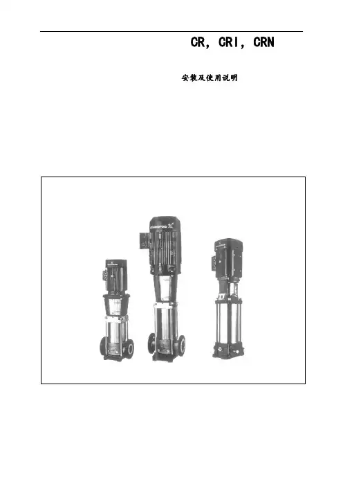
CR,CRI,CRN 安装及使用说明合格声明我们格兰富公司对本声明负全部责任, 本声明涉及的CR,CRI,CRN产品符合近似EEC 成员国法律的以下理事会准则:—机械制造(98/37/EEC)所用标准:EN292—电磁兼容性(89/336/EEC)所用标准:EN50 081-1及EN50 082-2—在一定电压围使用的电气设备的设计(73/23/EEC)所用标准:EN 60 335-1和EN 60 335-2-51.Bjerringbro /2001年2月1日Jan Strandgaard技术经理CR,CRI,CRN 安装及使用说明目录1. 处理 62. 型号规定 6 2.1 泵CR,CRI,CRN 1,3和5的型号规定 6 2.2 泵CR,CRI,CRN8和16的型号规定 6 2.3 泵CR, CRN 32,45,64和90的型号规定63. 应用 64. 技术参数7 4.1 环境温度7 4.2 液体温度7 4.3 轴封的最大允许工作压力和液体温度7 4.4 最小进口压力7 4.5 最大进口压力8 4.6 最小流量8 4.7 电气参数8 4.8 启动和停机频率8 4.9 尺寸与重量84.10 声压级85. 安装86. 电气连接96.1 变频器应用97. 启动98. 维护保养99. 防霜1010. 服务1010.1服务组件1011. 联轴器调节1012. 故障诊断表1113. 废物处理11开始安装之前,务必认真阅读本安装与使用说明书,安装和使用还要符合当地法规的要求。
1. 处理CR,CRI,CRN 1,3,5和CR,CRN 8,16泵的马达上提供了起吊孔,该孔绝不能用来起吊整台水泵。
当要吊起整台泵时,留意以下各项:●配有格兰富MG马达的CR,CRI,CRN 1,3,5和CR,CRN 8,16泵可以使用皮绳或者类似的绳索套在泵头上起吊。
●配有功率小于11kw(包括11kw)的格兰富MG马达的CR,CRN32,45,64和90泵,应使用泵头上的起吊孔起吊。
服务顾问指导手册目录一常用配件价格二养护品说明三常见故障说明四常见的客户抱怨应对相应的话术五机电部分项目维修时间常用配件价格逸动1。
6 常规项目收费明细(1.5T除外)1 致尚XT 常规项目收费明细(1。
5T除外)2 睿骋常规项目收费明细3 CS75常规项目收费明细4CS35 常规项目收费明细5 CX20 常规项目收费明细6 悦翔常规项目收费明细7 悦翔V3 常规项目收费明细8 悦翔V7 常规项目收费明细9 悦翔V5 常规项目收费明细10 奔奔MINI 常规项目收费明细11 新奔奔常规项目收费明细12 志翔常规项目收费明细13一、养护品说明方案名称保养部位使用产品保养时机间隔周期效果指数便捷型发动机内部发动机保护剂新车磨合时(二保)15000公里★★★★☆方案名称保养部位使用产品保养时机间隔周期效果指数便捷型发动机内部发动机保护剂新车磨合时(二保)15000公里★★★★☆方案名称保养部位使用产品保养时机间隔周期效果指数便捷型发动机内部新车磨合保护剂新车磨合时5000公里★★★★☆方案名称保养部位使用产品保养时机间隔周期效果指数便捷型喷油嘴喷油嘴系统清洁剂加油门没劲2。
0万公里★★★★☆方案名称保养部位使用产品保养时机间隔周期效果指数便捷型进气系统进气系统清洁剂气门与活塞润滑不良2.0万公里★★★★☆方案名称保养部位使用产品保养时机间隔周期效果指数保护型水箱连接管路水道冷却系统保护剂换冷却液时更换部件时3万公里★★★★☆制动系统故障解决方案方案名称保养部位使用产品保养时机间隔周效果指数期增强型制动盘刹车四件更换油时2万公里★★★★刹车片分泵导向销轮毂凸缘套轮胎换位时检查轮毂时★方案名称保养部位使用产品保养时机间隔周期效果指数清洗型空调风道蒸发器表面空调清洗剂春夏秋冬均可空调异味时10000公里换季★★★★☆三.常见故障说明发动机部分序号故障描述故障分析1 发动机启动异响1.解释2000公里左右属于挺筒异响属于正常。
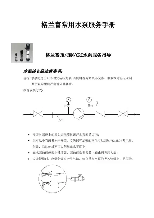
格兰富常用水泵服务手册格兰富CR/CRN/CRI水泵服务指导水泵的安装注意事项:前提:水泵的进出口必须安装压力表,否则将视为系统不完善。
很多故障将无法判断所以希望能严格遵守此要求。
推荐安装方式:•安装时泵座上的箭头表示流体流经水泵时的方向;•泵可以垂直或者水平安装,要确保有足够的空气可以到达马达的冷却风扇。
但是,马达绝对不可以倒放在水平面上;•在水泵的两侧装上伸缩器,泵的两端都要装上截止阀和压力表;•安装管道时,应避免管道产生气堵,特别是在水泵的吸入管道上,见图示;•安装时如果有下列情况,必须在水泵附近安装一个真空阀:排出管总是从泵开始向下倾斜;存在虹吸管影响的危险;有必要防止不干净的液体回流;•请在对水泵和管路进行连接之前,确认已经对管路进行了必要的清洗。
切记不能用水泵来冲洗管道,不能在水泵安装好进出管路后,再进行管路焊接等,主要是避免可疑物或焊渣等进入水泵内;•安装完后,如果不使用,用挡物盖住水泵,避免水和其他异物进入风扇及接线盒内;•如果水泵室外安装,强烈建议水泵电机安装防雨蓬;•如果水泵为变频控制,强烈建议对1.5KW 以下的电机加装LC滤波器,对于其它功率的电机,也建议加装滤波器。
在水泵未充满液体和彻底排空气之前,不要启动水泵。
水泵的调试(含注意事项):前提:确定水电已经到位!•关闭排出口的截止阀,完全打开吸入口的截止阀;•取出泵顶端的灌液塞,给水泵缓慢地灌液,灌好后重新安装回灌液塞并拧紧;•打开排气阀给水泵排气,同时稍微打开排出口的截止阀;•启动水泵并检查转向,马达的风扇上标有水泵的正确转向;•继续排气,同时把排出口侧的截止阀开的更大一些;•当排气阀流出的液体稳定后,关闭排气阀,并打排出口侧的截止阀;•调整水泵工作曲线在额定扬程和流量(参考水泵铭牌);•确认水泵运行电流和电压,保护设置最大不能超过电机额定电流;•详细记录并归档保存。
严禁闭阀运行,最小流量至少应为最大流量的10% 。
泵的铭牌上标有泵的流量和扬程水泵常见故障及排除:序号常见故障排除方案1 电机反转更换任意2相电源线的相序2 水泵有噪音a)气蚀噪音(调整出口阀门,水泵噪音会减少),出口压力表是否有抖动?如有,要排气。
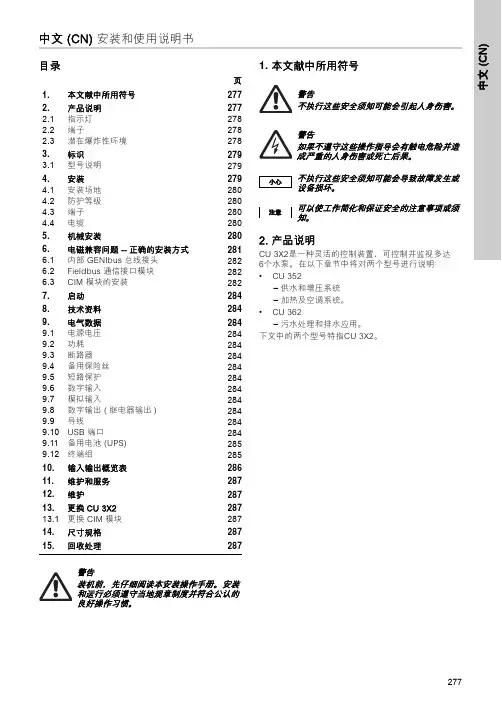
中文 (C N )277中文 (CN) 安装和使用说明书目录页1. 本文献中所用符号2. 产品说明CU 3X2是一种灵活的控制装置,可控制并监视多达6个水泵。
在以下章节中将对两个型号进行说明:•CU 352– 供水和增压系统– 加热及空调系统。
•CU 362– 污水处理和排水应用。
下文中的两个型号特指CU 3X2。
1.本文献中所用符号2772.产品说明2772.1指示灯2782.2端子2782.3潜在爆炸性环境2783.标识2793.1型号说明2794.安装2794.1安装场地2804.2防护等级2804.3端子2804.4电缆2805.机械安装2806.电磁兼容问题 --正确的安装方式2816.1内部 GENIbus 总线接头2826.2Fieldbus 通信接口模块2826.3CIM 模块的安装2827.启动2848.技术资料2849.电气数据2849.1电源电压2849.2功耗2849.3断路器2849.4备用保险丝2849.5短路保护2849.6数字输入2849.7模拟输入2849.8数字输出 (继电器输出)2849.9导线2849.10USB 端口2849.11备用电池 (UPS)2859.12终端组28510.输入输出概览表28611.维护和服务28712.维护28713.更换CU 3X228713.1更换 CIM 模块28714.尺寸规格28715.回收处理287警告装机前,先仔细阅读本安装操作手册。
安装和运行必须遵守当地规章制度并符合公认的良好操作习惯。
警告不执行这些安全须知可能会引起人身伤害。
小心不执行这些安全须知可能会导致故障发生或设备损坏。
注意可以使工作简化和保证安全的注意事项或须知。
中文 (CN)278图 1CU 3X2举例*部分帮助文本适用于整个显示屏,其余文本适用于显示屏的部分系列。
2.1 指示灯CU 3X2具有1个绿色指示灯和1个红色指示灯。
绿色指示灯在电源接通后亮起。
GRUNDFOS说明书Sololift2 C-3安装和使用说明书Sololift2 C-3/qr/i/97771617中文 (CN)2中文 (CN) 安装和使用说明书翻译原来的英文版本安装与操作指导对格兰富Sololift C-3进行了说明。
章节1-3介绍了以安全的方式拆包、安装并启动本产品所需的信息。
章节 4-8 介绍了有关产品的重要信息,以及有关服务、故障查找和产品处置的信息。
目录页1. 概述1.1 本文献中所用符号1.1.1 对死亡或人身伤害危险的警告1.1.2 其他重要事项1.概述21.1本文献中所用符号22.接收产品32.1运输产品33.安装产品33.1机械安装33.2电气连接34.产品介绍44.1产品描述44.2设计用途44.3泵送液体45.维修产品45.1服务文献45.2维护和服务45.3服务指导56.对产品进行故障查找67.技术数据78.产品处置7开始安装前,请先阅读本文件。
安装和操作必须遵守当地规章制度并符合公认的良好操作习惯。
对于8岁及以上的儿童以及身体、感官或精神上存在缺陷或缺乏经验和知识的成人,如果他们处于监督之下,或已被教授本设备的安全使用方法,并了解所涉及的危险,可以使用本设备。
不允许儿童将本设备作为玩具。
严禁没有监督的儿童对本设备进行清洁和维护。
危险指示危险情况,如果不避免,可能导致死亡或严重的人身伤害。
警告指示危险情况,如果不避免,可能导致死亡或严重的人身伤害。
注意指示危险情况,如果不避免,可能导致轻度或中度的人身伤害。
带白色图形符号的蓝色或灰色圆圈表示必须采取行动以避免发生危险。
红色或灰色圆圈加一斜线,也可能带黑色图形符号,表示不得采取或必须停止的行为。
使工作更轻松的提示和建议。
中文 (C N )32. 接收产品2.1 运输产品3. 安装产品3.1 机械安装若提升站与洗衣机、洗碗机、浴缸与/或淋浴器连接,我们强烈建议安装LC A2警报装置(配件)。
若水箱内的水位过高,LC A2警报器将发出警报声响并自动关闭洗衣机或洗碗机。
Hydro 系统常见故障及排除格兰富技术热线:400-820-2196服务邮箱地址: Service-cn@涉及电控部分的维修,服务人员需具备低压电工证。
格兰富技术热线:400-820-2196服务邮箱地址: Service-cn@Hydro 系统日常维护保养格兰富水泵故障排除表打开接线盒盖前,应断开电源! 水泵进出口必须安装压力表,否则将视为系统不完善。
很多故障将无法排除!!格兰富技术热线:400-820-2196格兰富水泵使用维护要点1.水泵进口必须为正压,进口水位必须高于水泵(如低则必须加装止回阀),出口管路上水泵与阀门之间的应安装压力表。
2.水泵使用前必须先进水、盘动、排气,确保泵内有水后才能启动水泵。
3.电机接线需对照电机铭牌及接线盒内接线图要求接线,根据电机的额定电流(In)设置热保护,电流设定< IN。
4.水泵运行压力应在额定曲线范围内,通过调整出口阀门开口度大小来调整水泵的运行压力(出口压力减进口压力的值应符合铭牌标示),电机运行电流须在额定电流以内。
5.泵体部分在正常情况下免维护。
6.无加油嘴,因此电机轴承无需保养,正常情况下2万小时需更换(电机生产日期开始)。
7.有润滑嘴的电机应按照电机铭牌说明,定期加注高温锂基脂,停用6个月以上的电机启动前应先润滑。
润滑脂型号:SHELL牌 高温锂基脂RL38.电机首次加油后每运行2千小时轴承需加一次润滑脂(高温锂基脂),电机上有具体标注;(当年生产的电机)。
9.GRUNDFOS的电机4KW以下启动频率不能超过100次/小时,其它电机则不能超过20次/小时,特殊的电机例外。
10.对于长时间停用的水泵,排空泵内的液体。
再次启动需按新泵启动要求操作(2-4条)。
11.在寒冷的场所不使用水泵时应做好防冻处理,排空泵内的液体。
12.使用联轴器的卧式水泵,需每三个月检查同心度和地脚螺栓的紧固。
13.日常巡视需注意观察水泵运行状况:a.水泵工作压力---水泵进出口压差符合工作曲线范围b.水泵的震动/噪音---震动引起噪音,可根据电机噪音指标+3db判断水泵运行震动是否正常c.水泵电流---根据经验值运行电流在额定电机的80-90%d.电机温升---F级绝缘的温升155℃减环境温度e.电机轴承温升---应小于80℃f. 检查电控箱的电源的质量、电源线的连接是否牢固、电机的接线是否正确松动格兰富技术热线:400-820-2196格兰富污水泵故障排除表污水泵故障排除之前应该咨询潜污泵曾经出现过的现象,然后检查保护回路的功能,否则将视为盲目判断。
KEY FEATURES AND BENEFITS• Configure limits, trip points, delays, and more...• See Detailed alarm and warning information • View pump run times and starts• Copy and save settings from one MP 204 to another • Read, print, and/or email full performance reports with the MP 204 report function • Full I&O manual available on Grundfos GO for MP 204ELECTRONIC PUMP PROTECTION MADE SIMPLESP pumps are made to be very strong indeed. But that does not mean they cannot benefit from extra protection that prolongs their lifetime and safeguards them against external threats. That is why we created the MP 204 motor protection unit.Made especially for pumps by pump specialists, it was designed to bring you pump protection that is as simple to use as it is efficient. Our engineers packed it full of all the protection features you need—but kept it easy to install, set, and use.PROTECT YOUR PUMPS AGAINST EXTERNAL THREATSThe MP 204 protects pump motors against incoming station powersupply issues such as: undervoltage, overvoltage, current unbalance, and other variations in power supply. So even if your external power supply is not entirely steady, your SP pump will remain as reliable as ever. Very importantly, the extra protection also reduces wear, thereby prolonging the motor’s lifespan.Reduced power consumption is a strong indication that the pump is about to run dry, so the MP 204 will immediately stop the pump if the power consumption drops below 60 percent. And with SP pumps, the Tempcon temperature sensor ensures that the pump is stopped if it becomes too hot—for example if a foreign object jams the pump.SP Motor ProtectionGRUNDFOS MP 2043-YEARSYSTEM WARRANTY WHEN USED WITH A GRUNDFOS PUMP AND MOTORTECHNICAL DATAGruallrightsreseSTAY IN TOUCH FROM A DISTANCEWe believe in open protocols. That is why your MP 204 solutioncan be connected to virtually any SCADA system, allowing youremote access to your pump data anywhere. You can control thepump, change the settings, and access information such as energy。
GriffService Manual1. Content1. Content (2)2. Symbol (4)3. Description (5)3.1. Layout for Griff. (6)3.2. Operating Diagrams (7)3.3. Identification Plate (8)4. General information (9)5. Preparation (9)5.1. Transportation (9)6. Placing/application (9)7. Water supply (9)8. Air supply (9)8.1. Adjustment of air (9)9. Power supply (10)10. Installation Guide (10)11. Connecting the unit (11)11.1. Connections (11)11.1.1. Water: (11)11.1.2. Products: (11)11.1.3. Electricity: (11)12. Preparing the unit (11)13. Testing the unit (11)13.1. Testing the Rinse function: (11)13.2. Testing the Foam function: (11)13.3. Testing the Sanitise function: (12)13.4. Checking the unit for leaks (12)14. S ervice / Maintenance instructions (12)14.1. Recycling and scrapping (12)15. Descaling (12)16. Troubleshooting (12)17. Specifications (13)18. Electric diagram (14)19. Pump curve (15)IMPORTANT SAFETY INSTRUCTIONSWARNINGWhen using electric appliances, basic precautions should always be followed, including the following:1. Read all the instructions before using the appliance.2. To reduce the risk of injury, close supervision is necessary when an appliance is used near children.3. Do not touch moving parts.4. Only use attachments recommended or sold by the manufacturer.5. Do not use outdoors.Exception: This item is not required if the appliance has been evaluated for outdoor use.6. For a cord-Connected appliance, the following shall be included:- To disconnect, turn all controls to the off ("O") position, then remove plug from outlet.- Do not unplug by pulling the cord. To unplug, grasp the plug, not the cord.- Unplug from outlet when not in use and before servicing or cleaning.- Do not operate any appliance, with a damaged cord or plug, after appliance malfunctions or ifdropped or damaged in any manner. Return appliance to the nearest authorized service facility for examination, repair, electrical or mechanical adjustment.7. For a portable appliance - To reduce the risk of electrical shock, do not put Griff in water or other liquid. Do not place or store appliance where it can fall or be pulled into a tub or sink.8. For a grounded appliance - connect to a properly grounded outlet only. See Grounding Instructions.SAVE THESE INSTRUCTIONS611000242612312986 7 5 4 10211311 E n g l i s h (E N )3.1. Layout for Griff.Single user unit1. Water inlet2. Pump3. Flow Switch4. Injector block5. Chemical inlet, block6. Sanitizer inlet, block7. Air inlet, block8. Compressor9. Water outlet10. Switch, Compressor 11. Control box 12. Power supply7110003126E1F E2F WCPFSTCCCCD AEJRVCOEJ HVHCE n g l i s h (E N )3.2. Operating Diagrams according to ISO14617F. Filter.FST. Flow-switch and -trigger.C. Check valve.CP. Centrifugal pump.EJ. Ejector.HV. Hydraulic valve.HC. Hose connection.A. Air supply.D. Outlet.E. Inlet, detergent.W. Water inlet.CO. Compressor RV. Regulating valveDisinfection Foam13E n g l i s h (E N )17. SpecificationsTechnical DataWater110Vac 60 Hz versionConnection type inlet3/4" GHT (ASME B1.20.7 3/4" - 11,5-NH)Recommended inlet pipe dimensions (min)3/4"Local outlet 1/2" quick coupler Pump pressure 52 psi / 3,7 bar Operational pressure 82-116 psi / 5,7-8 bar Operational flow range 1,5-3 gal/min / 5-11 l/min Water consumption - foaming 1,5 gal/min / 5 l/min Water consumption - spraying 1,5 gal/min / 5 l/min Water consumption - rinsing 3 gal/min / 11 l/minMin. inlet pressure 29 psi/4 gal/min / 2 bar @ 11 l/minMax. inlet pressure 72 psi/5 bar Max. water temperature 158°F/70°C Electricity Power consumption 1 kW Nom. current 11,1 ASupply1/PE 110 Vac ±10% 60 HzSecurity of electrical wiring 12A Electrical cable; L1, L2, L3, PE 1,5 mm 2Nozzles (recommended)Rinsing nozzle 15/12Foam nozzle Foam lance 100 mmSpray nozzle 15/12GeneralNumber of products 2IP classIP54Max. hose length (recommended)82 ft/25 m (50 ft/15 m)Sound level ISO 11202Below 70 dB Weight66 lbs/30 kgDimensions H x W x D19,7 x 19,7 x 10,2 inch / 500 x 500 x 260 mmDimensions are without cart/trolley140123456789AB CDEFABCDEFK A Y E l e c t r i c a lR e v i s i o n A I n i t i a l e r s a n1D C C &EF SN æs t e s i d eA n t a l s i d e r 1S i d eP r o j e k t K a yD a t o 18-03-2013D o k u m e n t n u m m e r 110 003 041-M 1UNP E-M 2UNP E-B 2-F 1123456UUNNP EP E P u m pC o m p r e s s o rF l o w A i r-W 1123-W 2123-W 3123-W 412-W 51212-K 1/X 1-K 1/X 23-K 1/X 3-K 1/X 4-K 1/X 5-K 1-B 3E n g l i s h (E N )18. Electric diagram1* 115 - 230 V, 60 HzE n g l i s h (E N )CM1-3 1*115 - 110/115, 60HzItem no: 110006232CRecommended spare partsPièces de rechange conseilléesPiezas de recambio recomendadas171416 123131141267515 9810110003058b1819N r.No.P o s ./R e f .!D escription Désignation DesignaciónKay Nr.No.Fuse 12 A 1 110003166 83900071 Fusible 12 AFusible 12AFuse 0,315 A 2 110003167 83900070 Fusible 0,315 AFusible 0,315 AController board 3 110002644 92214059 Carte processeurPlaca controladoraHose Teflon4 110003159 92214026 Téflon de flexibleConducto de TeflonScrews for Cover 5 110003168 88020017 Vis du couvercleTornillos para la cubiertaReed switch for Flow switch6 110003165 83050051 Interrupteur rouge du régulateur de débitInterruptor de lámina para el interruptor de caudalFlow switch7 110002638 83050050 Régulateur de débitInterruptor de caudalScrews for compressor switch8 110003170 88020018 Vis pour l'interrupteur du compresseurTornillos para el interruptor del compresorCompressor switch9 110002636 83055100 Interrupteur du compresseurInterruptor del compresorSelector knob10 110003156 92214011 Bouton de sélectionManija selectoraSS braided hose11 110005172 85032013 Tuyau tressé acier inoxydableManguera de acero inoxidable trenzadoCompressor 12 110002632 84550001 CompresseurCompresorCover 13 110006336 92214058 CouvercleCubiertaThermal overload 14 110002622 83000800 Surcharge thermiqueSobrecarga térmicaPumpe cpl.15 110002650 8460087 Pompe, complèteBomba completaWall bracket 16 110002629 92213793 Support muralSoporta para pared2011732211918547201516119141391210811000663611000323021N r.No. P os ./Re f.! D escriptionDésignationDesignaciónKay Nr.No. * 1 110003096 Air Check valve•* 2 110004434 Product check valve • * 3 110005516 O-ring kit(110002952)4 110002501 Selector valve axel* 5 110005516 O-ring kit(110002956)6 110005516 O-ring kit(110003172)7 110003156 Selector knob110002633 Block cpl.8 110003205 Mounting kit for cart9 110003204 Mounting kit for unit on cart10 110003197 Mounting kit productholder11 110003207 Mounting kit for caster12 110003206 Mounting kit for wheels13 110003177 Castor cpl.14 110003176 Back wheel cpl.15 110002985 CouplerCoupleurAcoplador16 110004658 Bracket for nozzles and cables 17 110005516 O-ring kit(0635021)18 110005516 O-ring kit(110002955)19 110002392 Flexible pressure piece 20 110005516 O-ring kit(110002961)21 110004219 Injector kitInstallation2020,33/4" GHT 104Ø0,317,24,74,717110004860A:USA22N o .: 110006232E 05/2019 P r i n t e d i n D e n m a r k。
0 1 0 10 1 0 10 1 0 10 1 0 1 0 1 0 1 0 1 0 1 0 1 0 1 0 1 0 1 0 1 0 1 0 1 00 1 0 1 0 1 0 1 0 1 0 1 0 1 0 1 0 1 0 1 0 1 0 1 0 1 0 1 0 1 0 1 0 1 0 1 0 1 0 1 0 1 0 1 0 1 0 1 0 1 0 1 0 1 0 1 0 1 0 1 0 1 0 1 0 1 0 1 0 1 0 1 0 1 0 1 0 1 0 1 0 1 0 1 0 1 0 1 0 1 0 1 0 1 0 1 0 1 0 1 0 1 0 1 0 1 0 1 0 1 0 1 0 10 1 0 1 0 1 0 10 1 0 1 0 1 0 1 0 1 0 1 0 1 0 1 0 1 0 1 0 1 0 1 0 1 0 1 0 1 0 1 0 1 0 1 0 1 0 1 0 1 0 1 0 1 0 1 0 1 0 1 0 1 0 1 0 1 0 1 0 1 0 1 0 1 0 1 0 0 1 0 1 0Gefran Softwarepreventive maintenance alarms• Closed loop for Melt pressure and control of roller tension• Management of motors in synch• Recipes for work parameters and machine parameters • Confi gurable trends of process variables • Exportable historical fi les• Weekly programmer for programmed on/off• Scalability of application on many hardware architectures • Tested solutions based on Gefran Hardware/SoftwareProfi leGF_PACK EXTRUSION is Gefran’s solution for complete control of extruders and extrusion lines.GF_PACK EXTRUSION is supplied as preinstalled software on Gefran HW, within which Gefran has inserted a series of preconfi gured functions.GF_PACK EXTRUSION consists of standard hardware and software modules:• Operator interface with terminals and Gefran Industrial PCs, 6.5”, 10.4”, 12.1” and 15” colour monitors and touch screen • Gefran GILOGIK II I/O modules with digital and analogue inputs and outputs and temperature sensors • Temperature control modules, Gefran Geflex single loop and multiloop, with on-board SSRs • Application software preconfigured and preloaded on operator interfaceGF_PACK EXTRUSION contains all typical functions for managing an extruder and an extrusion line.gf_pack extrusion2Functions» Thermoregulation• Max 96 configurable temperature control zones• Division of temperature control zones into groups• Parameterisation and configuration of temperature control loop from dedicated application pages• Distributed temperature control with Geflex controllers• Centralized temperature control with GILOGIK II (R-TC8 modules)• Pages with trend graphics on all enabled temperature zones, with acquired setpoint/value trend» Motors control and management• Up to 16 preconfigured motors (extrusion, hopper, mixer, vacuum pump, drag, cut, auxiliary)• Dedicated pages for motors Start/Stop, with status feedback, from operator panel• Preconfigured synchronism function activated from operator panel• Automatic management of gear ratio for motors enabled for synchronism • Dedicated pages for scaling analogue input and output values• Pages with trend graphics for all acquired analogue variables• Configuration of up to 4 setpoints on analogue input• Up to 4 closed loops for speed controlAs default, machine movement control signals are managed with analogue values (-10 / +10 Vdc).For use of drives in Fieldbus (CANopen) connection, reference values can be managed with read/write on the bus.» Other functionalityIn addition to machine control functions, the packet offers:• Recipe management (exportable via USB port)• Printing of configurable parameters and pages• Videocamera via Ethernet (Netcam) for real time remote control of system “hot points”• Tele-assistance via modem and Internet• Complete diagnostics of hardware (PLC) with function state and information on version of configured I/O modules• Multilanguages management with UNICODE support (Italian, English, French, German, Chinese, etc.)• Password level management for access to pages or change of data items • Easy access to system from local and remote by Ethernet (centralisation, diagnostics, upgrade)• Availability of a user setting log• Quality control of defined parameters• Programmed system autostart• Counters for managing maintenance of significant data, configurable runtimesgf_pack extrusion The following diagram shows a film extrusion line, highlighting its main functions with specific reference to use of devices in the Gefran catalogue.3gf_pack extrusion4SupplyGF_PACK EXTRUSION is uspplied on a DVD, with which you can install the data and information needed to programme an extrusion line.The installation DVD contains the following:• User manual with information on functions and operation of pages used to manage an extrusion line• Configuration manual with information on source software structure and instructions for possible changes. A list of available data/variables and of standard functions is included• General electrical diagram for connecting the operator panel, I/Os and possible connection in case of distributed temperature control• Graphic utility for guided configuration of structure for passage to various application pages. The utility is also used to configure access levels for page call To programme and implement special functions, the development PC requires the configuration tools contained in Gefran Automation Builder (G.A.B.).By using the programming languages you can change the standard functions contained in GF_PACK EXTRUSION to adapt them to specific machine needs.The information and data on the DVD are subject to a user license that is inserted with the supply.GF_PACK EXTRUSION is available in various configurations according to the type and complexity of the application:EXTRULABO• Application software packet for small/medium extruders• Dynamic pages configurable for up to 16 temperature control zones, up to 3 motors in synch, 1 fast control loopEXTRUCOMP• Application software packet for estruders• Dynamic pages configurable for up to 24 temperature control zones, up to 10 motors in synch, 1 fast control loopEXTRUPIPE• Application software packet for extruder lines• Dynamic pages configurable for up to 48 temperature control zones, up to 16 motors in synch, up to 4 fast control loopsThe various confi gurations (EXTRULABO, EXTRUCOMP and EXTRUPIPE) are matched with one of the terminals of the GF_VEDO ML, GF_VEDO HL or DIGISTAR II series equipped with the VxWorks operating system.The selected terminal is supplied with the OS and selected operative packed preinstalled.gf_pack extrusion5 Technical DataThe automation architecture required for the GF_PACK EXTRUSION solution calls for:Operator interface based on the following terminals of the GF_VEDO ML seriesOperator interface based on the following terminals of the GF_VEDO HL seriesModel GF_VEDO ML 65GF_VEDO ML 104GF_VEDO ML 121GF_VEDO ML 150Type262K TFT colorsDimension 6.5”10.4”12.1”15”ResolutionVGA(640x480)SVGA(800x600)SVGA(800x600)XGA(1024x768) Processor Type Geode LX900 / Frequency 600MHz / Core x86Standard2 x Ethernet 10/100 Mbps4 x USB 2.0 Host1 x RS4852 x PS21 x TF keyboardModel GF_VEDO HL 121GF_VEDO HL 150Type262K TFT colorsDimension12.1”15”ResolutionSVGA(800x600)XGA(1024x768) Processor Type Intel Pentium Celeron - Intel Celeron Mobile / Frequency 600 - 1500MHzStandard2 x Ethernet 10/100 Mbps2 x USB 1.1 Host1 x RS4852 x PS21 x TF keyboardgf_pack extrusion6Geflex controllersModel GFX GFXTERMO4GFX4Characteristics1 channel (hot/cold)Solid state relay embedded DIN rail mounting 4 channels (hot/cold)Solid state relay command DIN rail mounting 4 channels (hot/cold)Solid state relay embedded DIN rail mountingGILOGIK II series remote I/O modules with GDNet (Ethernet) connection to operator interfaceCodeR-E16R-U16R-EU16R-A/D8R-D/A4R-D/A8R-MA6R-TC8R-C3Characteristics,Channels number 24Vdc PNP digital inputs 16824Vdc 2APNP digital outputs 16816mA, V analog inputs,potentiometer , strain gauge (16bit)86mA, V analog outputs (16bit)4 - 86Temperature inputs (18bit) (J, K)8Counter inputs1(5KHz)3 (250KHz)All Input / Output signals are optically isolated.gf_pack extrusion7Distributed solutionGF_VEDOGEFLEXGILOGIK IIModbus RS485Centralized control using R-TC8 modules in the GILOGIK II series, with GDNet (Ethernet) connection to operator interface.Centralized solutionGF_VEDOGILOGIK IIR-TC8 temperature controlDistributed control using Gefl ex controllers, with serial Modbus connection to operator interface.GEFRAN spa Via Sebina, 7425050 Provaglio d’Iseo (BS) - ItalyPh. +39 030 9888.1 - Fax +39 030 9839063Email:*******************:gf_pack extrusionOrder codePRECONFIGURED SOLUTIONSF039561EXTRULABOApplication software package for small/medium extruders. Dynamically confi gurable up to 16 temperature control loops, up to 3 motor control loops with synchronization and 1 fast closed control loop.F039562EXTRUCOMPStandard application software package for extruders. Dynamically confi gurable up to 24 temperature control loops, up to 10 motor control loops with synchronization and 1 fast closed control loop.F039563EXTRUPIPEApplication software package for complete extrusion lines. Dynamically confi gurable up to 48 temperature control loops, up to 16 motor control loops with synchronization and 4 fast closed control loops.SOLUTIONS FOR SYSTEM INTEGRATORSF039564EXTRUSYSOpen application software package for complete extrusion lines. Dynamically confi gurable up to 96 temperature control loops, up to 30 motor control loops with synchronization and 10 fast closed control loops. Includes SEVEN programming environment for PLC and HMI, and a 3 days technical training in our laboratories in Provaglio d’Iseo (Italy). (travel and lodgings expenses excluded).DTS_GF_PACK-EXTRUSION_1209_ENGNote:The EXTRULABO, EXTRUCOMP, EXTRUPIPE, packages must be ordered together with a DIGISTAR II series industrial PC with VxWorks O.S.。