Analog Power物料运用
- 格式:pdf
- 大小:1.21 MB
- 文档页数:21

power在芯片行业的用法全文共四篇示例,供读者参考第一篇示例:随着科技的不断进步,芯片在各个领域的应用也越来越广泛。
而在芯片行业中,电力是一个至关重要的因素。
电力在芯片行业的应用范围十分广泛,包括芯片的供电、功耗管理、散热等方面。
本文将从这些方面来详细探讨电力在芯片行业的用法。
电力在芯片的供电方面起着至关重要的作用。
芯片作为电子产品的核心部件,需要稳定的电力供应来正常工作。
电力供应不稳定或者功率不足会导致芯片无法正常工作,甚至损坏。
在芯片设计中,电力供应就显得至关重要。
芯片设计师需要考虑芯片的功耗情况,选择合适的供电方案,确保芯片在各种工作环境下都能正常工作。
电力在芯片的功耗管理方面也起着重要作用。
随着芯片技术的不断发展,芯片的功耗越来越成为一个关注的焦点。
为了延长电子产品的续航时间,降低产品的发热量,芯片设计师需要采取一系列措施来有效管理芯片的功耗。
这其中就包括使用节能的电路设计、采用低功耗的工艺制程等措施。
通过合理的功耗管理,可以提高芯片的性能表现,延长产品的使用时间,减少产品的散热需求,提高产品的可靠性。
电力在芯片的散热方面也起着重要作用。
随着芯片的工作频率越来越高,散热问题也变得越来越突出。
芯片工作时会产生大量的热量,如果不能有效散热,会导致芯片温度过高而影响芯片的正常工作。
芯片设计师需要采取一系列措施来有效散热,以确保芯片在各种工作环境下都能正常工作。
这包括设计合理的散热结构、增加散热风扇、采用高导热材料等措施。
通过有效的散热设计,可以降低芯片的工作温度,提高芯片的稳定性和可靠性。
电力在芯片行业的用法十分广泛,涉及到芯片的供电、功耗管理、散热等方面。
芯片设计师需要考虑这些因素,设计出稳定性能优异的芯片产品。
随着技术的不断发展,电力在芯片行业的应用也将不断创新,为电子产品的发展带来更多可能。
希望未来电力在芯片行业的应用能够更加创新,为电子产品的发展带来更多的机遇和挑战。
【本文共XXX字】第二篇示例:近年来,随着科技的不断发展和进步,人们对于芯片行业中的power(电源)的重要性也逐渐增加。
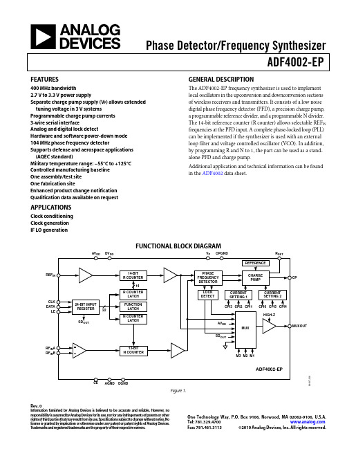
Phase Detector/Frequency SynthesizerADF4002-EPRev. 0Information furnished by Analog Devices is believed to be accurate and reliable. However , no responsibility is assumed by Analog Devices for its use, nor for any infringements of patents or other rights of third parties that may result from its use. Specifications subject to change without notice. No license is granted by implication or otherwise under any patent or patent rights of Analog Devices. T rademarks and registered trademarks are the property of their respective owners.One Technology Way, P.O. Box 9106, Norwood, M A 02062-9106, U.S.A.Tel: 781.329.4700 Fax: 781.461.3113 ©2010 Analog Devices, Inc. All rights reserved.FEATURES400 MHz bandwidth2.7 V to3.3 V power supplySeparate charge pump supply (V P ) allows extended tuning voltage in 3 V systemsProgrammable charge pump currents 3-wire serial interfaceAnalog and digital lock detectHardware and software power-down mode 104 MHz phase frequency detectorSupports defense and aerospace applications (AQEC standard)Military temperature range: −55°C to +125°C Controlled manufacturing baseline One assembly/test site One fabrication siteEnhanced product change notification Qualification data available on requestAPPLICATIONSClock conditioning Clock generation IF LO generation GENERAL DESCRIPTIONThe ADF4002-EP frequency synthesizer is used to implement local oscillators in the upconversion and downconversion sections of wireless receivers and transmitters. It consists of a low noise digital phase frequency detector (PFD), a precision charge pump, a programmable reference divider, and a programmable N divider. The 14-bit reference counter (R counter) allows selectable REF IN frequencies at the PFD input. A complete phase-locked loop (PLL) can be implemented if the synthesizer is used with an external loop filter and voltage controlled oscillator (VCO). In addition, by programming R and N to 1, the part can be used as a stand-alone PFD and charge pump.Additional application and technical information can be found in the ADF4002 data sheet.FUNCTIONAL BLOCK DIAGRAMCLK DATA LEREFRF IN A RF IN B09187-001Figure 1.ADF4002-EPRev. 0 | Page 2 of 8TABLE OF CONTENTSFeatures .............................................................................................. 1 Applications ....................................................................................... 1 General Description ......................................................................... 1 Functional Block Diagram .............................................................. 1 Revision History ............................................................................... 2 Specifications ..................................................................................... 3 Timing Characteristics . (4)Absolute Maximum Ratings ............................................................5 Thermal Characteristics ...............................................................5 ESD Caution...................................................................................5 Pin Configuration and Function Descriptions ..............................6 Typical Performance Characteristics ..............................................7 Outline Dimensions ..........................................................................8 Ordering Guide .. (8)REVISION HISTORY11/10—Revision 0: Initial VersionADF4002-EPRev. 0 | Page 3 of 8SPECIFICATIONSAV DD = DV DD = 3 V ± 10%, AV DD ≤ V P ≤ 5.5 V , AGND = DGND = CPGND = 0 V , R SET = 5.1 kΩ, dBm referred to 50 Ω, T A = T MAX to T MIN , unless otherwise noted. Operating temperature range is −55°C to +125°C. Table 1.Parameter M in Typ M ax Unit Test Conditions/Comments RF CHARACTERISTICS RF Input Sensitivity −10 0 dBm RF Input Frequency (RF IN ) 5 400 MHz For RF IN < 5 MHz, ensure slew rate (SR) > 4 V/μs REF IN CHARACTERISTICS REF IN Input Frequency 20 300 MHz For REF IN < 20 MHz, ensure SR > 50 V/μs REF IN Input Sensitivity 10.8 AV DD V p-p Biased at AV DD /2 (ac coupling ensures AV DD /2 bias) REF IN Input Capacitance 10 pF REF IN Input Current ±100 μA PHASE FREQUENCY DETECTOR (PFD)Phase Detector Frequency 2104 MHz ABP[2:1] = 00 (2.9 ns antibacklash pulse width) CHAR G E PUMP Programmable I CP Sink/Source High Value 5 mA R SET = 5.1 kΩ Low Value 625 μAAbsolute Accuracy2.5 % R SET = 5.1 kΩ R SET Range3.0 11 kΩ I CP Three-State Leakage 1 nA T A = 25°C I CP vs. V CP 1.5 % 0.5 V ≤ V CP ≤ (V P − 0.5 V) Sink and Source Current Matching 2 % 0.5 V ≤ V CP ≤ (V P − 0.5 V) I CP vs. Temperature 2 % V CP = V P /2 LOGIC INPUTS Input High Voltage, V IH 1.4 VInput Low Voltage, V IL 0.6 VInput Current, I INH , I INL ±1 μA Input Capacitance, C IN 10 pF LOGIC OUTPUTS Output High Voltage, V OH 1.4 V Open-drain output, 1 kΩ pull-up resistor to 1.8 V DV DD − 0.4 V CMOS output Output High Current, I OH 100 μA Output Low Voltage, V OL 0.4 V I OL = 500 μA POWER SUPPLIES AV DD 2.7 3.3 V DV DD AV DD V V P AV DD 5.5 V AV DD ≤ V P ≤ 5.5 V I DD 3(AI DD + DI DD ) 5.0 6.0 mA I P 0.4 mA T A = 25°C Power-Down Mode 1 μA AI DD + DI DD NOISE CHARACTERISTICS Normalized Phase Noise Floor (PN SYNTH )4, 5 −222 dBc/Hz PLL loop bandwidth = 500 kHzNormalized 1/f Noise (PN 1_f )4, 6−119 dBc/Hz Measured at 10 kHz offset; normalized to 1 GHz1 AV DD = DV DD = 3 V.2Guaranteed by design. Sample tested to ensure compliance. 3T A = 25°C; AV DD = DV DD = 3 V; RF IN = 350 MHz. The current for any other setup (25°C, 3.0 V) in mA is given by 2.35 + 0.0046 (REF IN ) + 0.0062 (RF); RF frequency and REF IN frequency in MHz. 4All phase noise measurements were performed with a Rohde & Schwarz FSUP26 phase noise test system using the EVAL-ADF4002EBZ1 evaluation board and the ultralow noise, 100 MHz OCXO from Wenzel (Part No. 501-16843) as the PLL reference. 5The synthesizer phase noise floor is estimated by measuring the in-band phase noise at the output of the VCO and subtracting 20logN (where N is the N divider value) and 10logf PFD . PN SYNTH = PN TOT − 10logf PFD − 20logN. 6The PLL phase noise is composed of 1/f (flicker) noise plus the normalized PLL noise floor. The formula for calculating the 1/f noise contribution at an RF frequency (f RF ) and at a frequency offset (f) is given by PN = P 1_f + 10log(10 kHz/f) + 20log(f RF /1 GHz). Both the normalized phase noise floor and the flicker noise are modeled in ADIsimPLL.ADF4002-EPRev. 0 | Page 4 of 8TIMING CHARACTERISTICSAV DD = DV DD = 3 V ± 10%, AV DD ≤ V P ≤ 5.5 V , AGND = DGND = CPGND = 0 V , R SET = 5.1 kΩ, dBm referred to 50 Ω, T A = T MAX to T MIN , unless otherwise noted. Operating temperature range is −55°C to +125°C. Table 2.Parameter Limit 1Unit Descriptiont 1 10 ns min DATA to CLK setup time t 2 10 ns min DATA to CLK hold time t 3 25 ns min CLK high duration t 4 25 ns min CLK low duration t 5 10 ns min CLK to LE setup time t 6 20ns min LE pulse width1Guaranteed by design, but not production tested.Timing Diagram09187-022Figure 2. Timing DiagramADF4002-EPRev. 0 | Page 5 of 8ABSOLUTE MAXIMUM RATINGST A = 25°C, unless otherwise noted. Table 3.Parameter Rating AV DD to GND 1 −0.3 V to +3.6 V AV DD to DV DD −0.3 V to +0.3 VV P to GND 1−0.3 V to +5.8 V V P to AV DD −0.3 V to +5.8 VDigital I/O Voltage to GND 1−0.3 V to DV DD + 0.3 V Analog I/O Voltage to GND 1 −0.3 V to V P + 0.3 VREF IN , RF IN A, RF IN B to GND 1−0.3 V to AV DD + 0.3 V Operating Temperature Range Industrial −55°C to +125°C Storage Temperature Range −65°C to +125°C Maximum Junction Temperature 150°C Lead Temperature, Soldering Vapor Phase (60 sec) 215°C Infrared (15 sec) 220°C Transistor CountCMOS 6425 Bipolar 3031GND = AGND = DGND = CPGND = 0 V.Stresses above those listed under Absolute Maximum Ratingsmay cause permanent damage to the device. This is a stress rating only; functional operation of the device at these or any other conditions above those indicated in the operationalsection of this specification is not implied. Exposure to absolute maximum rating conditions for extended periods may affect device reliability. This device is a high performance RF integrated circuit with an ESD rating of <2 kV , and it is ESD sensitive. Proper precautions should be taken for handling and assembly.THERMAL CHARACTERISTICSTable 4. Thermal ImpedancePackage Type θJA Unit TSSOP (RU-16)150.4 °C/WESD CAUTIONADF4002-EPRev. 0 | Page 6 of 8PIN CONFIGURATION AND FUNCTION DESCRIPTIONSRCP CPGND CLKCE DGNDRF IN RF IN A AV DD REF V P DD 09187-002Figure 3. Pin Configuration (Top View)G GADF4002-EPRev. 0 | Page 7 of 8TYPICAL PERFORMANCE CHARACTERISTICS09187-031–40–35–30–25–20–15–10–500100200300400500600P O W E R(d B m )FREQUENCY (MHz)Figure 4. RF Input Sensitivity –35–30–25–20–15579111315P O W E R(d B m )FREQUENCY (MHz)09187-033Figure 5. RF Input Sensitivity, Low Frequency –70–80–90–100–110–120–130–140–150–160P H A S E N O I S E (d B c /H z )FREQUENCY OFFSET (Hz)09187-031Figure 6. Integrated Phase Noise (400 MHz, 1 MHz, 50 kHz)–130–135–140–145–155–160–165–170–175–180100k1M 10M100M 1GP H A S E N O I S E (d B c /H z )PFD FREQUENCY (Hz)–15009187-033Figure 7. Phase Noise (Referred to CP Output) vs. PFD FrequencyREF –4dBmMKR1 1.000 MHzRES BW 20kHzSWEEP 21ms (601pts)–10009187-030Figure 8. Reference Spurs (400 MHz, 1 MHz, 7 kHz)ADF4002-EPRev. 0 | Page 8 of 8OUTLINE DIMENSIONS0.150.051.20COPLANARITY0.10COMPLIANT TO JEDEC STANDARDS MO-153-ABFigure 9. 16-Lead Thin Shrink Small Outline Package [TSSOP](RU-16)Dimensions shown in millimetersORDERING GUIDEodel Temperature Range Package Description Package OptionADF4002SRU-EP −55°C to +125°C 16-Lead TSSOP RU-16 ADF4002SRU-EP-RL7 −55°C to +125°C 16-Lead TSSOPRU-16©2010 Analog Devices, Inc. All rights reserved. Trademarks and registered trademarks are the property of their respective owners. D09187-0-11/10(0)。

电子行业转贴电子专业英语引言随着电子行业的蓬勃发展,电子专业英语在该行业中变得越来越重要。
掌握电子专业英语不仅有助于从事电子工程相关工作的人员流畅地与国际伙伴交流,还能提高在电子行业中的竞争力。
本文将转贴一些常用的电子专业英语词汇和短语,希望能对电子行业从业人员和学生提供帮助。
1. 电子器件和设备的英语词汇•Semiconductors(半导体)•Resistors(电阻器)•Capacitors(电容器)•Inductors(电感器)•Transistors(晶体管)•Diodes(二极管)•Integrated Circuits(集成电路)•Microcontrollers(微控制器)•Printed Circuit Boards(印刷电路板)•Power Supplies(电源)2. 电子行业的工作职位和专业术语•Electrical Engineer(电气工程师)•Electronics Technician(电子技术员)•Circuit Designer(电路设计师)•Hardware Engineer(硬件工程师)•Analog Design Engineer(模拟设计工程师)•Digital Design Engineer(数字设计工程师)•Quality Control Engineer(质量控制工程师)•Test Engineer(测试工程师)•Firmware Engineer(固件工程师)•Project Manager(项目经理)3. 电子行业常见缩写和首字母缩写•PCB: Printed Circuit Board(印刷电路板)•IC: Integrated Circuit(集成电路)•LED: Light-Emitting Diode(发光二极管)•BOM: Bill of Materials(物料清单)•SMT: Surface Mount Technology(表面贴装技术)•ESD: Electrostatic Discharge(静电放电)•EMC: Electromagnetic Compatibility(电磁兼容性)•PCB: Personal Computer Board(个人电脑板)•ADC: Analog-to-Digital Converter(模数转换器)•DAC: Digital-to-Analog Converter(数模转换器)4. 交流时常用的电子专业英语短语•Can you please expln that in simple terms?(你能简单地解释一下吗?)•I’m sorry, I didn’t understand what you just sd.(对不起,我刚才没听懂你说的话。

SimpliPhi Power PHI BatteryOptimized Energy Storage & Management for Residential & Commercial Applications Utilizing Efficient, Safe, Non-Toxic, Energy Dense Lithium Ferrous Phosphate (LFP) ChemistryINTEGRATION GUIDE: VICTRONSimpliPhi Your Energy Security and Independenceand gain control of your own power.SimpliPhi helps you manage your power as a personal resource. Anytime, anywhere, SimpliPhi energy storage systems optimize integration of any power generation source – solar, wind, generator –on or off grid and protects your home and mission-critical business functions from power outages and intermittency. SimpliPhi storage technology eliminates operating temperature constraints, toxic coolants and the risk of thermal runaway and fire. Safe lithium ferrous phosphate. No cobalt. No hazards.SimpliPhi’s battery technology utilizes the industry’s most environmentally benign chemistry combined with proprietary architecture and power electronics (BMS) that eliminate the need for cooling or ventilation to create products that provide energy security and resiliency.SimpliPhi Power offers proprietary, commercially available energy storage and management systems that are safe, non-toxic, reliable, durable, efficient, highly scalable, and economical over the lifetime of the PHI Battery.T able of Contents1.0 – Introduction (4)2.0 – Battery Bank Sizing (4)2.1 – Discharge Calculation: Inverter Power Bank Sizing (4)2.2 – Charge Calculation: Charge Controller Power Sizing (5)3.0 – Victron BMV-700 Installation & Setup (5)3.1 – Standard Features (6)3.2 – Installation – Connections (6)3.3 – Installation – Quick Start Guide (7)3.4 – Victron – Available Interfaces (8)4.0 – Program Settings for PHI Batteries (8)4.1 – Depth of Discharge (8)4.2 – PHI 3.8 General Settings with Victron (8)4.3 – Victron BMV-700 Programming Settings (9)4.4 – Inverter / Charger Settings (10)4.5 – MPPT Settings (11)4.6 – ESS Settings (11)5.0 – Specifications & Warranty (13)6.0 – SimpliPhi Technical Support (13)1.0 – IntroductionThis integration guide covers the recommended set up and configuration of Victron equipment for optimizing performance with SimpliPhi PHI 3.8 kWh Batteries. More information on SimpliPhi products can be found on our website: https:///.If the Victron product you are looking for is not covered in this integration guide, the parameters listed here should be used as a general guide.The specific Victron product(s) installation and setup covered in this Integration Guide include: •Victron BMV-7xx Series Battery MonitorProgramming parameters described herein relate to PHI 3.8 Battery general settings requirements as well as to the following Victron Products:•Victron Inverter / Chargerso Phoenix VE.Direct Invertero MultiPlus and Quatro Inverter / Charger•MPPT Solar Charge Controllers•ESSo Generalo Color Control or Venus GXBased on tests and evaluations, the following parameters (refer to tables below) have been established. More information on Victron products can be found on their website: https:///. More information on the Victron BMV-700 can be found on their website: https:///battery-monitors/bmv-700.2.0 – Battery Bank SizingA properly sized PHI battery bank should be at least double (2x) the kW rating of the inverter(s) and have a C/2 rating greater than the maximum charge controller rating. Depending on the specifications of the equipment used in the system, sizing the PHI Battery bank based on these two criteria may yield different results. Therefore, the best practice is to calculate the PHI Battery bank based on both criteria and use the greater of the two results as the minimum quantity. We can compare these two calculation methods assuming the nomenclature below:•Battery rated continuous power = Bat kWh (typically @ C/2)•Inverter power full load = Inv kW•Maximum battery charge current = I BatChrgMax•PV charge controller maximum = I PVChrgMax•Recommended minimum number of batteries = B#Discharge equation: B#Inv≥ Inv kW / Bat kWhCharge equation: B#PV≥ I PVChrgMax / I BatChrgMax2.1 – Discharge Calculation: Inverter Power Bank SizingTo optimize the PHI Battery bank and protect against over-discharge (voiding the battery Warranty), the PHI Battery bank should be sized at least double (2x) the kW rating of the inverter.Discharge Example: B#Inv≥ Inv kW / Bat kWh•Inverter is rated at 8 kW•PHI Battery is rated at 3.8 kWh, therefore the C/2 load rating is 1.9 kWB#Inv≥ 8 kW / 1.9 kW = 4.21A properly sized PHI Battery bank based on maximum discharge would have a minimum of 5 PHI Batteries. This ensures no greater than C/2 battery load. If the PHI Battery bank has fewer batteries than calculated, special care must be taken with the inverter settings to limit the load below the specified rating of the PHI Battery. These settings are described in the following sections of this Integration Guide.2.2 – Charge Calculation: Charge Controller Power SizingTo optimize solar harvesting, a properly sized PHI Battery bank should be able to accept the maximum PV charge current. To determine the minimum number of PHI Batteries required to optimize PV, divide the output of the charge controller(s) by the “max continuous charge current” per PHI Battery. Be sure to verify the “max continuous charge current” for the PHI Battery model that you’re using, because it may differ from C/2 depending on the model.Charge Example: B#PV≥ I PVChrgMax / I BatChrgMax•Maximum continuous charge current for PHI 3.8 kWh 48V = 37.5A•PV charge controller max = 80AB#PV≥ 80A/37.5A = 2.13A properly sized PHI Battery bank based on available PV charge would have a minimum of 3 PHI Batteries. This maximizes the use of available PV while ensuring the PHI Batteries are never stressed by overcharging. If the PHI Battery bank has fewer batteries than calculated, special care must be taken with the inverter settings to limit the charge rate below the specified rating of the PHI Battery. These settings are described in the following sections of this Integration Guide.In summary: When comparing the same system using these two calculations for sizing the PHI Battery bank, the minimum number of PHI Batteries should be the greater of the two results (Discharge Calculation & Charge Calculation). In this example, this translates into 5 PHI Batteries in the system.3.0 – Victron BMV-700 Installation & SetupThe BMV-7xx series products will follow the general installation and settings in this section. The BMV-700 is used as a specific example here. Other products in this series have additional capabilities (i.e., the BMV-702 has the capability to monitor an additional PHI Battery).The BMV-700 is a precision battery monitor that functions as a ‘fuel gauge’ and indicates time remaining in the PHI Battery bank. The remaining PHI Battery capacity depends on the ampere-hours consumed, discharge current, temperature, and the age of the PHI Battery. Ampere hours consumed are calculated by integrating the current flowing in or out of the PHI Battery. Complex software algorithms are utilized to take all these variables into account for an accurate reading. The monitor tracks several parameters regarding the state of charge of the PHI Battery which can be used to evaluate usage patterns and battery health.3.1 – Standard FeaturesThe BMV-700 standard features include:•Battery voltage, current, power, ampere-hours consumed and state of charge•Remaining time at the current rate of discharge•Programmable visual and audible alarm for alerts•Programmable relay, to turn off non-critical loads or to run a generator when needed•500 Amp quick connect shunt and connection kit•Shunt selection capability up to 10.000 Amps•VE Direct communication port - Stores a wide range of historical events, which can be used to evaluate usage patterns and battery health•Wide input voltage range: 9.5 – 95V•High current measurement resolution: 10 mA (0.01A)•Low current consumption: 2.9Ah per month (4mA) @12V and 2.2Ah per month (3mA) @ 24V•Bluetooth Smart dongle monitors your batteries on Apple or Android smartphones, tablets, Macbooks and other devices3.2 – Installation – ConnectionsFollow the instructions below to setup the BMV-700.CAUTION: Connect the Negative Pole of the PHI Battery last!1.Locate suitable place for 500A/50mV shunt and secure in place.2.Remove fuse from PHI Battery supply cable.3.Connect positive supply cable and appropriately sized PHI Battery positive cable to positive output ofPHI Battery bank and to the positive of the load/charger.4.From the “load and charger” side of the shunt, connect appropriately sized negative cable to theinverter or load/charger.5.Connect positive supply cable to +B1 on the shunt.6.Locate suitable place for the Victron meter and secure in place.7.Connect UTP cable to rear of battery monitor.8.Connect free end of UTP cable to battery shunt.9.Connect appropriately sized negative cable between the “battery only” side of the shunt and thenegative output of the PHI Battery bank. Replace Fuse in fuse holder ensuring it is fully seated. Please review Figure 1.0 below for additional detail.Figure 1.0 - BMV-700 Typical InstallationCAUTION: Connect the Negative Pole of the PHI Battery last!3.3 – Installation – Quick Start GuideAfter installation / connection, on initial startup, the BMV-700 “Setup Wizard” will automatically start. The following steps should be used to initialize the meter.1.BMV will automatically start the setup wizard.a.The scrolling text “Battery Capacity “will appear.i.Set the Ah capacity using the +/- buttons.ii.Pressing “select” after each digit is selected.iii.Calculate total bank capacity based on number of PHI Batteries in the bank.iv.Example: 75Ah x 3 Batteries = 225Ah.b.Press “setup” for 2 seconds to enter other parameters of the BMV.c.Press “select” to access the desired parameter.e the +/- buttons to customize the settings.e.For PHI 3.8 kWh Batteries, set parameters per Table 1.0 below.f.Zero Current calibration: Disconnect the Negative cable between the load and shunt and press“select”.g.Synchronize: press “select”.h.For any other settings, such as relay, temperature, or alarm settings, consult the BMV Manual.i.Press “setup” to end the wizard.The BMV should be setup for normal use at this time.If additional assistance is required, contact Victron Energy at:*********************** or call Victron at +31 (0)36 5359700CAUTION: If a firmware update is executed on Victron equipment, ALL the settings must bereverified.3.4 – Victron – Available InterfacesThe following interfaces are available from Victron to allow easy monitoring of the PHI Battery status / performance.•PC software BMV- Reader. Downloadable from Victron website in the support and downloads section.Uses the VE.direct to USB interface.•Color Control GX display featuring a 4.3-in color display can be connected to the BMV using VE.direct to USB interface.Ifadditionalassistanceisrequired,contactVictronEnergyat:**************************************+31 (0)36 5359700.4.0 – Program Settings for PHI BatteriesIn order to maintain the Warranty, it is critical to ensure that the appropriate settings for the desired Warranty are programmed in all the system components. This section will cover the basic concepts and settings for the PHI 3.8 Batteries as well as settings specific to Victron products.4.1 – Depth of DischargeIn order to optimize performance and the life of your system and PHI batteries, SimpliPhi Power recommends programming the equipment settings for 80% Depth of Discharge (DoD). This enables the batteries to achieve an expected 10,000 cycles. Greater DoD is possible, but will result in reduced cycle life.4.2 – PHI 3.8 General Settings with VictronThe general program settings for the PHI 3.8 Batteries with Victron products are outlined below.Table 1.0 - Settings for SimpliPhi PHI 3.8 kWh 24V / 48V Battery w/VictronGeneralBattery Curve FixedCapacity1 (Ah) 151Ah per PHI3.8 24V; (302Ah for 2, 453Ah for 3) 75Ah per PHI3.8 48V; (150Ah for 2, 225Ah for 3)Absorb Voltage (V) 28 / 56 Absorb Time .1 Hour (6 minutes) Float Voltage (V) 27 / 54 (typically Disable)Discharge Voltage "LBCO" (V) 25.1 / 50.2 (80%DoD)24.8 / 49.6 (90%DoD)24 / 48 (100%DoD)Re-Charge (V) 25.6 / 51.2Max Discharge/Charge Current (C/2)175A per PHI3.8 24V; (150A for 2, 225A for 3) 37.5A per PHI3.8 48V; (75A for 2, 112.5A for 3)Peukert Expo 1.05Charge Efficiency 95%SoC when Bulk Finished 95%Notes:• 1. Per PHI 3.8 Battery – These settings are calculated by multiplying the nominal per battery value times the # of batteries.•Levels are typical @ 25°C and may need adjusting at temperature extremes.•When performing rapid deep charge/discharge cycles, the PHI Battery should be allowed to "rest" 15 minutes in between.•Always refer to the SimpliPhi Power Manual and Warranty for the specific PHI Battery model.4.3 – Victron BMV-700 Programming SettingsTable 2.0 - Settings for SimpliPhi PHI 3.8 kWh 24V / 48V Battery w/Victron BMV-700 Battery MonitorBattery Capacity1 (Ah) 151Ah per PHI3.8 24V; (302Ah for 2, 453Ah for 3) 75Ah per PHI3.8 48V; (150Ah for 2, 225Ah for 3)Charged Voltage (V) 26.5 / 53.2Tail Current (%) 8 / 4Charge Detection Time (minutes) 1Peukert Exponent 1.05Charge Efficiency Factor (%) 98Current Threshold (A) 0.1Time to go Averaging Period (minutes) 3Notes:• 1. Per PHI 3.8 Battery – These settings are calculated by multiplying the nominal per battery value times the # of PHI Batteries.•Levels are typical @ 25°C and may need adjusting at temperature extremes.•When performing rapid deep charge/discharge cycles, the PHI Battery should be allowed to "rest" 15 minutes in between.•Always refer to the SimpliPhi Power Manual and Warranty for the specific PHI battery model.CAUTION: When battery quantities change, the capacity current settings must be reassessed.4.4 – Inverter / Charger SettingsThe program settings for the PHI 3.8 Batteries with Victron Inverter / Charger products are outlined below.Table 3.0 - Settings for SimpliPhi PHI 3.8 kWh 24V / 48V Battery w/Victron Inverter / ChargerVictron Connect Static Low Voltage CutoffOutput Voltage 230V Output Frequency 50Hz Dynamic CutoffOFFLow Battery Shutdown25.1V / 50.2V24.8V / 49.6V 24V / 48V Low Battery Restart & Alarm 27V / 54V Charge Detect27V / 54V ECO Mode Wake-up Minimum Power 15W ECO Mode Search Interval 2.5SVictron ConnectDynamic Low Voltage CutoffEnable Dynamic Cutoff ON Battery TypeCustomBattery Capacity 175A per PHI3.8 48VVoltage for Discharge 0A 25.1V / 50.2V 24.8V / 49.6V 24V / 48V Voltage for Discharge 8A Voltage for Discharge 23AVoltage for Discharge 66A25V / 50 V 24.6V / 49.1V 23.8V / 47.5VVE ConfigureGeneral TabSoC when Bulk Finished 95%Total Battery Capacity 1 151Ah @ 24V / 75Ah @ 48V: per batteryCharge Efficiency 95% VE ConfigureInverter TabDC Input Low Shut-Down 25.1V / 50.2V 24.8V / 49.6V 24V / 48VDC Input Low Restart 25.7V / 51.5V DC Input Low Pre-Alarm 25.5V / 51V Battery Type LithiumLithium > Yes Lithium Iron PhosphateAbsorb Voltage 28V / 56V Float Voltage27V / 54VCharge Current (C/2)1 Repeated Absorb Time .1 Hour (6 Minutes)Repeated Absorb Interval 7 DaysAbsorb Time.1 Hour (6 Minutes)Notes: • 1.Per PHI 3.8 Battery – These settings are calculated by multiplying the nominal per battery value times the # of batteries.•Levels are typical @ 25°C and may need adjusting at temperature extremes.•When performing rapid deep charge/discharge cycles, the PHI Battery should be allowed to "rest" 15 minutes in between.•Always refer to the SimpliPhi Power Manual and Warranty for the specific PHI Battery model.25.1V / 50.2V 25.1V / 50.2V24.8V / 49.6V 24.8V / 49.6V 24V / 48V24V / 48V 75A @ 24V DC / 37.5VDC @ 48V: per battery4.5 – MPPT SettingsThe program settings for the PHI 3.8 Batteries with Victron MPPT products are outlined below.Table 4.0 - Settings for SimpliPhi PHI 3.8 kWh 24V / 48V Battery w/Victron MPPT Battery Voltage 24V / 48V75A @ 24V DC / 37.5VDC @ 48V: per battery Max Charge Current (C/2)1Default Charge Settings OFFAbsorb Voltage 28V / 56VAbsorb Time .1 Hour (6 Minutes)Float Voltage 27V / 54VEqualization Voltage 27V / 54VAuto Equalization OFFTemperature Compensation OFFNotes:• 1. Per PHI 3.8 Battery – These settings are calculated by multiplying the nominal per battery value times the # of batteries.•Levels are typical @ 25°C and may need adjusting at temperature extremes.•When performing rapid deep charge/discharge cycles, the PHI Battery should be allowed to "rest" 15 minutes in between.•Always refer to the SimpliPhi Power Manual and Warranty for the specific PHI Battery model4.6 – ESS SettingsThe program settings for the PHI 3.8 Batteries with Victron ESS products are outlined below.Table 5.0 - Settings for SimpliPhi PHI 3.8 kWh 48V Battery w/Victron ESSVE Configure GeneralSoC when Bulk Finished 95%Total Battery Capacity175Ah per PHI3.8; (150Ah for 2, 225Ah for 3)Charge Efficiency 95%VE Configure Grid TabN/A No battery specific settingsVE Configure Inverter TabN/A Settings have NO EFFECT once ESS assistant is loadedVE Configure Charger TabN/A Settings have NO EFFECT once ESS assistant is loadedVE Configure Virtual Switch TabN/A Do NOT use VSVE Configure Assistants TabBattery System System uses LiFePo4 with other type BMSVE Configure Battery Type Selection Change battery type as suggestedSustain Voltage 50.2VDynamic Cut-Off Discharge Rate Dependent0.005C 50.2 49.6V 48V0.25C 50.2 49.6V 48V0.7C250.1 49.5V 48V2C249.7 49.1V 48VRestart Offset 1.2VVictron Default Absorption Voltage 54.4VMode Optimized (with BatteryLife)Control Without Grid Meter OFFInverter AC Output in use ONFeed-in Excess Solar charger Power ONPhase Compensation ONMinimum Discharge SoC390%Actual State of Charge Limit 95%BatteryLife State Self-consumptionLimit Charger Power OFFLimit Inverter Power OFFFronius Zero feed-in OFFFronius Zero feed-in active No battery specific settingsGrid setpoint 50WNotes:• 1. Per PHI 3.8 Battery – These settings are calculated by multiplying the nominal per battery value times the # of PHI Batteries.• 2. These levels exceed the warrantied recommended operating conditions.• 3. For BACKUP ONLY applications, set to desired backup level. This is the level batteries cycle to normally before recharge. If the grid fails, cut-off is determined by the Dynamic Cut-Off values.•Levels are typical @ 25°C and may need adjusting at temperature extremes.•When performing rapid deep charge/discharge cycles, the PHI Battery should be allowed to "rest" 15 minutes in between.•Always refer to the SimpliPhi Power Manual and Warranty for the specific PHI Battery model.5.0 – Specifications & WarrantyFor your reference:•See PHI 3.8 kWh 24V Specifications sheet.•See PHI 3.8 kWh 48V Specifications sheet.•See PHI 3.8 kWh 48V 10-Year Warranty. Failure to adhere to installation protocol will void Warranty.6.0 – SimpliPhi Technical SupportFor technical support related to your PHI 3.8 kWh Battery (or other SimpliPhi Power products), please contact us directly at:805.640.6700******************************。

功率放大器的分类1功率放大器功率放大器是一种电子管或半导体放大电路,它能够使输入信号的幅度增大到某一特定的值,从而使输出信号的功率增大。
它可以增加一个信号的幅值,降低其谐波失真等,从而改善其声音/图像质量,或实现信号传输要求。
比如一个小的声音,通过功率放大器的放大,就可以变得更大、更结实。
2功率放大器分类1.模拟功率放大器(Analog Power Amplifier):模拟功率放大器以电子管、集成放大器(INT)或双列管构成,主要用于模拟话音、音频、视频等信号的放大处理,有效地改善了音频和视频质量。
2.数字功率放大器(Digital Power Amplifier):数字功率放大器是以集成电路的形式构成,其采用数字信号处理技术,使得放大器更加紧凑和节能,适用于收音机、汽车音响,以及其他数字音频应用场景。
3.电源功率放大器(Power Supply Amplifier):电源功率放大器是一种用于增大电源输出功率的放大器,可实现固定电压或固定频率输出。
4.线性功率放大器(Linear Power Amplifier):线性功率放大器是一种使放大前后信号保持一致特性的放大器,具有良好的功率容量和高谐波抑制,是广泛应用的高性能放大器类型。
5.高频功率放大器(High Frequency Power Amplifier):高频功率放大器(即HFPA)是一种设备,主要用于放大高频信号,广泛应用于无线通信系统(如电话),改善信号传输要求,增强信号传输距离。
3工业用途功率放大器在无线电产品中的应用非常广泛,可以用于各种无线电设备,如收音机、收发信机、手持设备等,能够大大增加电路的输出功率,提高发射频率的稳定程度,提高信号的传输效率,减少失真率,同时节约功耗,以达到最佳发射效果。
此外,功率放大器也可以应用在医疗和科学研究领域,旨在推动超声波治疗和超声波影像扫描技术的发展。
使用功率放大器可以取得更好的超声治疗效果,提供更有效的护理。
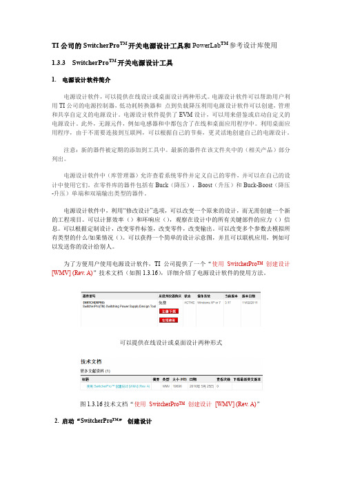
TI公司的SwitcherPro TM开关电源设计工具和PowerLab TM参考设计库使用1.3.3 SwitcherPro TM开关电源设计工具1. 电源设计软件简介电源设计软件,可以提供在线设计或桌面设计两种形式。
电源设计软件可以帮助用户利用TI公司的电源控制器,低功耗转换器和点到负载降压利用电源设计软件可以创建,管理和共享自定义的电源设计。
电源设计软件提供了EVM设计,可以用来借鉴或启动自定义的电源设计。
此外,无源元件,例如电感器和中都包含了在线和桌面应用程序中。
利用桌面应用程序,由于不需要连接到互联网,可以根据自己的节奏,更灵活地创建自己的电源设计。
注意:新的器件被定期的添加到工具中。
最新的器件在该文件夹中的(相关产品)部分列出。
电源设计软件中(库管理器)允许查看系统零件并定义自己的零件,并可以在自己的设计中使用它们。
在零件库的器件包括有Buck(降压),Boost(升压)和Buck-Boost(降压-升压)单端和双端输出类型的器件。
电源设计软件中,利用“修改设计”选项,可以改变一个原来的设计,而无需创建一个新的工程项目。
可以计算效率()和环响应(),观察在设计中的所有关键部件的应力()信息。
可以根据定制设计,改变零件标签,改变零件,改变输出。
可以改变多个参数去模拟所有类型的什么/如果情况()。
可以获得一个简单的设计示意图,并且可以联机应用,例如可以发送你的设计给别人。
为了方便用户使用电源设计软件,TI公司提供了一个“使用SwitcherPro™ 创建设计[WMV] (Rev. A)”技术文档(如图1.3.16),详细介绍了电源设计软件的使用方法。
可以提供在线设计或桌面设计两种形式图1.3.16技术文档“使用SwitcherPro™ 创建设计[WMV] (Rev. A)”2. 启动“SwitcherPro™”创建设计登录下载或者在线使用电源设计软件,如图1.3.17所示,利用电源设计软件可以“Create a new design(创建一个新的设计)”或者“Copy existing design(复制一个已经存在的设计)”图1.3.17 启动电源设计软件3. 利用“Create a new design”创建一个新的设计单击“Create a new design”,如图1.3.18所示,创建一个新的设计可以从“start by selecting a device(选择器件)”或者“start by entering specifications(选择规范(特性))”开始。
模拟电子器件原理与应用教程介绍此教程旨在提供模拟电子器件的基本原理和应用知识,帮助研究者理解和应用模拟电子器件的工作原理。
什么是模拟电子器件?模拟电子器件是指用于处理和传输连续信号的电子器件。
与数字电子器件不同,模拟电子器件能够处理连续的信号,例如音频、视频和传感器数据等。
常见的模拟电子器件以下是一些常见的模拟电子器件:1. 操作放大器(Operational Amplifier,简称 Op-Amp):Op-Amp 是用来放大和处理模拟信号的重要器件。
它具有高增益和低失真的特性,广泛应用于放大、滤波、混频等电路中。
2. 模拟开关(Analog Switch):模拟开关用于控制模拟信号的开关状态,可以实现信号的开关、切换和多路复用等功能。
3. 模拟-数字转换器(Analog-to-Digital Converter,简称 ADC):ADC 用于将模拟信号转换为数字信号,常用于将声音、电压等连续信号转换为数字形式进行处理。
4. 数字-模拟转换器(Digital-to-Analog Converter,简称 DAC):DAC 用于将数字信号转换为模拟信号,常用于音频、视频等数字信号的输出。
模拟电子器件的应用模拟电子器件在各个领域都有广泛的应用,以下是一些常见的应用场景:1. 音频放大器:模拟电子器件常用于音频放大器中,用于放大音频信号并驱动扬声器。
2. 传感器接口:模拟电子器件可以接收来自传感器的模拟信号,并进行信号调理和处理,以提供准确的传感器测量结果。
3. 通信系统:模拟电子器件在无线通信系统和有线通信系统中发挥重要作用。
例如,模拟电子器件可以用于射频信号调制解调、频率混频、滤波等功能。
4. 电源管理:模拟电子器件可以用于电源管理电路中,例如电压调节器和电池充放电控制等。
总结模拟电子器件是处理和传输连续信号的重要工具。
通过了解模拟电子器件的基本原理和常见应用,研究者可以更好地理解和应用模拟电子器件,为各种应用场景提供支持。
protel dxp 2004 元件库中的常用元件初学protel DXP 碰到最多的问题就是:不知道元件放在哪个库中。
这里收集了DXP2004常用元件库下常见的元件。
使用时,只需在libary中选择相应的元件库后,输入英文的前几个字母就可看到相应的元件了。
通过添加通配符*,可以扩大选择范围。
下面这些库元件都是DXP 2004自带的不用下载。
########### DXP2004下Miscellaneous Devices.Intlib元件库中常用元件有:电阻系列(res*)排组(res pack*)电感(inductor*)电容(cap*,capacitor*)二极管系列(diode*,d*)三极管系列(npn*,pnp*,mos*,MOSFET*,MESFET*,jfet*,IGBT*)运算放大器系列(op*)继电器(relay*)8位数码显示管(dpy*)电桥(bri*bridge)光电耦合器( opto* ,optoisolator )光电二极管、三极管(photo*)模数转换、数模转换器(adc-8,dac-8)晶振(xtal)电源(battery)喇叭(speaker)麦克风(mic*)小灯泡(lamp*)响铃(bell)天线(antenna)保险丝(fuse*)开关系列(sw*)跳线(jumper*)变压器系列(trans*)????(tube*)(scr)(neon)(buzzer)(coax)晶振(crystal oscillator)的元件库名称是Miscellaneous Devices.Intlib, 在search栏中输入*soc 即可。
########### DXP2004下Miscellaneous connectors.Intlib元件库中常用元件有:(con*,connector*)(header*)(MHDR*)电阻AXIAL无极性电容RAD电解电容RB-电位器VR二极管DIODE三极管TO电源稳压块78和79系列TO-126H和TO-126V场效应管和三极管一样整流桥D-44 D-37 D-46单排多针插座CON SIP双列直插元件DIP晶振XTAL1电阻:RES1,RES2,RES3,RES4;封装属性为axial系列无极性电容:cap;封装属性为RAD-0.1到rad-0.4电解电容:electroi;封装属性为rb.2/.4到rb.5/1.0电位器:pot1,pot2;封装属性为vr-1到vr-5二极管:封装属性为diode-0.4(小功率)diode-0.7(大功率)三极管:常见的封装属性为to-18(普通三极管)to-22(大功率三极管)to-3(大功率达林顿管)电源稳压块有78和79系列;78系列如7805,7812,7820等79系列有7905,7912,7920等常见的封装属性有to126h和to126v整流桥:BRIDGE1,BRIDGE2: 封装属性为D系列(D-44,D-37,D-46)电阻: AXIAL0.3-AXIAL0.7 其中0.4-0.7指电阻的长度,一般用AXIAL0.4 瓷片电容:RAD0.1-RAD0.3. 其中0.1-0.3指电容大小,一般用RAD0.1电解电容:RB.1/.2-RB.4/.8 其中.1/.2-.4/.8指电容大小.一般<100uF用RB.1/.2,100uF-470uF用RB.2/.4,>470uF用RB.3/.6二极管: DIODE0.4-DIODE0.7 其中0.4-0.7指二极管长短,一般用DIODE0.4 发光二极管:RB.1/.2数码管:Dpy集成块: DIP8-DIP40, 其中8-40指有多少脚,8脚的就是DIP8贴片电阻0603表示的是封装尺寸与具体阻值没有关系但封装尺寸与功率有关通常来说0201 1/20W0402 1/16W0603 1/10W0805 1/8W1206 1/4W电容电阻外形尺寸与封装的对应关系是:0402=1.0x0.50603=1.6x0.80805=2.0x1.21206=3.2x1.61210=3.2x2.51812=4.5x3.22225=5.6x6.5常用元件分类Protel DXP元件库分类元件的总库名元件的分库名中文名称Fairchild SemiconductorFSC Discrete BJT.IntLib 三极管FSC Discrete Diode.IntLib 二极管FSC Discrete Rectifier.IntLib IN系列二极管FSC Logic Flip-Flop.IntLib 40系列FSC Logic Latch.IntLib 74LS系列FSC Logic Gate.IntLib 74系列门电路C-MAC MicroTechnologyC-MAC MicroTechnology 晶振Dallas SemiconductorDallasMicrocontroller 8-Bit.IntLib 存储器International RectifierIR Discrete SCR.IntLib 可控硅IR Discrete Diode.IntLib 二极管KEMET ElectronicsKEMET. Chip. Capacitor..IntLib 粘贴式电容MotorolaMotorola Discrete BJT.IntLib 三极管Motorola.Discrete.Diode.IntLib 1N系列稳压管Motorola Discrete JFET.IntLib 场效应管Motorola Motorola.Discrete.MOSFET.IntLib MOS管Motorola Discrete SCR.IntLib 可控硅Motorola Discrete TRIAC.IntLib 双向可控硅Motorola PowerManagementV oltage Regulator.IntLib 电源LM系列Motorola Amplifier Operational Amplifier.IntLib LM358运放National SemiconductorNSC Audio Power Amplifier.IntLib LM38、48系列NSC Analog Timer Circuit.IntLib LM555NSC Analog Timer Circuit.IntLib 三极管NSC Discrete Diode.IntLib IN系列二极管NSC Discrete Diode.IntLib 1N系列稳压管NSC Logic Counter.IntLib CD40系列NSC Logic Counter.IntLib 74系列NSC Power Mgt V oltageRegulator.IntLib 电源块子78系列79(TO3B与TO220引脚不同)NSC Converter Analog to Digital.IntLib ADC0809,DAC0832NSC Power Mgt Switching Regulator.IntLib LM2596系列ON SemiconductorON Semi Logic Counter.IntLib 74系列ON Semi Logic Counter.IntLib 晶振Simulation Simulation Sources.IntLib 信号源Simulation Voltage Source.INTLIB 信号源ON Semi Power Mgt voltage Regulator.IntLib 317,337,2576系列ST MicroelectronicsST Analog Timer Circuit.IntLib LM555ST Discrete BJT.IntLib 2N系列三极管ST Operational Amplifier.IntLib TL084系列ST Logic Counter.IntLib 40、74系列ST Logic Flip-Flop.IntLib 74系列4017ST Logic Switch.IntLib 4066系列ST Logic Latch.IntLib 74系列ST Logic Register.IntLib 40系列ST Logic Special Function.IntLib 40系列ST PowerMgt V oltage Reference.IntLib TL、LM38系列ST Power Mgt Voltage Regulator.IntLib 电源块子78(TO-92封装)78xxABV(TO220封装) LM317系列Teccor ElectronicsTeccor Discrete TRIAC.IntLib 双向可控硅Teccor Discrete SCR.IntLib 可控硅Texas InstrumentsTI Analog Timer Circuit.IntLib 555系列TI Converter Digital to Analog.IntLib D/A转换器TI Converter Analog to Digital.IntLib A/D转换器TI Logic Decoder Demux.IntLib SN74LS138TI Logic Flip-Flop.IntLib 逻辑电路74系列TI Logic Gate 1.IntLib 逻辑电路74系列TI Logic Gate 2.IntLib 逻辑电路74系列TI Operational Amplifier.IntLib TL系列功放块定时器NE555P 在库TI analog timer circit.Intlib中。