DURLON密封技术手册.Image.Marked
- 格式:pdf
- 大小:2.13 MB
- 文档页数:76
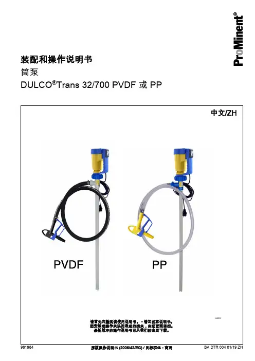
筒泵DULCO ®Trans 32/700 PVDF 或 PP装配和操作说明书原版操作说明书 (2006/42/EG) / 目标群体:商用981984BA DTR 004 01/19 ZH整阅读使用说明书。
• 请勿丢弃说明书。
或操作失误而造成的损失,由运营商承担。
本的操作说明书可从我们的主页下载。
本文件使用中性意义上按照语法的男性方式来使文本更易读。
始终以相同的方式称呼女士和男士。
我们请女性读者理解文章中的这种简化。
请阅读补充说明。
信息说明书中给出了设备正确操作或易于您操作的重要信息。
警告提示警告提示详细描述了危险情况,请参阅 Ä 章节 2.1 “警告提示标识”第 7 页。
本文件中可能使用以下标识强调操作说明、参考、列表、结果以及其它相关内容:一般同等对待补充说明补充说明2目录目录1功能、稳定性和供货范围 (4)2安全说明章节 (7)2.1 警告提示标识 (7)2.2 用户资格 (8)2.3 按规定使用 (8)2.4 可能出现的滥用 (8)2.5 安全 (9)2.5.1 泵和电机的安全提示 (9)2.5.2 喷嘴的安全提示 (10)2.6 声压级 (10)3储存和运输 (11)3.1 运输 (11)3.2 包装的废弃处理 (11)4装配和调试 (12)4.1 泵的装配 (12)4.2 电机说明和过电流触发 (12)5操作 (13)6每次使用后的清洁 (15)7维修、故障和备件 (16)7.1 检查/维修 (16)7.2 故障排除 (18)7.3 DULCO®Trans 的备件 (18)7.3.1 DULCO®Trans 32/700 PP 备件组件 (18)7.3.2 DULCO®Trans 32/700 PVDF 的备件组件 (19)7.3.3 电机备件 (20)7.3.4 泵的备件 (22)7.3.5 喷嘴的备件 (24)7.3.6 配件 (25)8旧零部件处理 (26)9技术参数一览表 (27)9.1 技术数据,PP 规格 (27)9.2 技术数据,PVDF 规格 (28)9.3 功率图 (29)9.4 带有主要尺寸的比例图 (29)10欧共体/欧盟机械符合性声明 (30)11索引 (31)31 功能、稳定性和供货范围如需转移液体,这种筒泵是理想的解决方案。
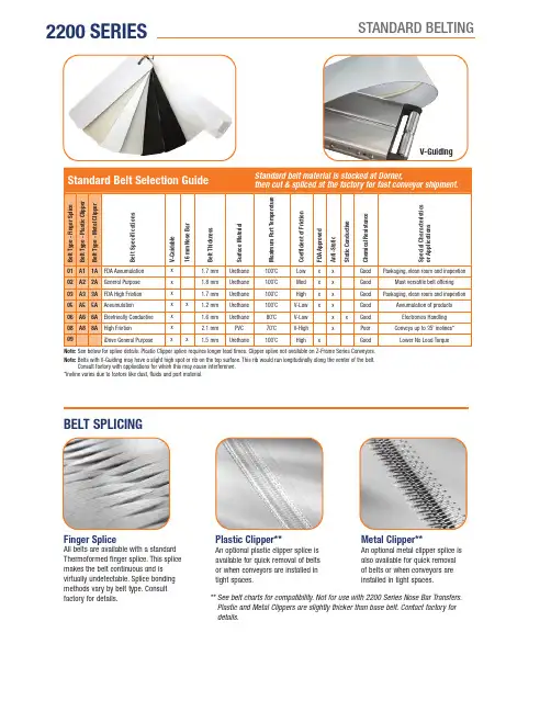
2200 SERIESSTANDARD BELTINGBELT SPLICINGPlastic Clipper**An optional plastic clipper splice is available for quick removal of belts or when conveyors are installed in tight spaces.Finger SpliceAll belts are available with a standard Thermoformed finger splice. This splice makes the belt continuous and is virtually undetectable. Splice bonding methods vary by belt type. Consultfactory for details.Metal Clipper**An optional metal clipper splice is also available for quick removal of belts or when conveyors are installed in tight spaces.** S ee belt charts for compatibility. Not for use with 2200 Series Nose Bar Transfers. Plastic and Metal Clippers are slightly thicker than base belt. Contact factory fordetails.V-GuidingStandard Belt Selection GuideStandard belt material is stocked at Dorner,B e l t T y p e - F i n g e r S p l i c eB e l t T y p e - P l a s t i cC l i p p e rB e l t T y p e - M e t a lC l i p p e rB e l t S p e c i f i c a t i o n sV -G u i d a b l e16 m m N o s e B a rB e l t T h i c k n e s sS u r f a c e M a t e r i a lM a x i m u m P a r t T e m p e r a t u r eC o e f f i c i e n t o f F r i c t i o nF D A A p p r o v e dA n t i -S t a t i cS t a t i c C o n d u c t i v eC h e m i c a l R e s i s t a n c eS p e c i a l C h a r a c t e r i s t i c s o r A p p l i c a t i o n s01A11A FDA Accumulation x 1.7 mm Urethane 100˚C Low x x Good Packaging, clean room and inspection02A22A General Purpose x 1.8 mm Urethane 100˚C Med x x Good Most versatile belt offering 03A33A FDA High Friction x 1.7 mm Urethane 100˚C High x x Good Packaging, clean room and inspection05A55A Accumulation x x1.2 mm Urethane 100˚C V-Low xx Good Accumulation of products 06A66A Electrically Conductive x 1.6 mm Urethane 80˚C V-Low x xGood Electronics Handling 08A88AHigh Friction x 2.1 mm PVC 70˚C V-High xPoor Conveys up to 35˚ inclines*09iDrive General Purposexx 1.5 mmUrethane100˚CHighxGoodLower No Load TorqueNote: See below for splice details. Plastic Clipper splice requires longer lead times. Clipper splice not available on Z-Frame Series Conveyors.Note: B elts with V-Guiding may have a slight high spot or rib on the top surface. This rib would run longitudinally along the center of the belt.Consult factory with applications for which this may cause interference.*Incline varies due to factors like dust, fluids and part material.2200 SERIESSPECIALTY BELTINGB e l t T y p e - F i n g e r S p l i c eB e l t T y p e - P l a s t i cC l i p p e rB e l t T y p e - M e t a lC l i p p e rB e l t S p e c i f i c a t i o n sV -G u i d e a b l e16 m m N o s e B a rB e l t T h i c k n e s sS u r f a c e M a t e r i a lM a x i m u m P a r t T e m p e r a t u r eC o e f f i c i e n t o f F r i c t i o nF D A A p p r o v e dA n t i -S t a t i cS t a t i c C o n d u c t i v eC h e m i c a l R e s i s t a n c eS p e c i a l C h a r a c t e r i s t i c s o r A p p l i c a t i o n s19Nose bar High friction x 0.7 mm Urethane 100˚C High x x Good Nose bar, high friction 50Heat Resistant 1.3 mm Silicone 180˚C Low xV-Good High temperature 53Translucent x0.5 mm Urethane 100˚C V-Low x GoodBack lit inspection54F44F FDA Sealed Edge**x 1.6 mm Urethane 80˚C Low x x Good Packaging, clean room and inspection 55F55F FDA Sealed Edge**x 1.6 mm Urethane 80˚C High xx Good Packaging, clean room and inspection 566F Cut Resistant x 2.1 mm Urethane 100˚C Med.x Good Oily product release, metal stamping 577F Cut Resistant x 2.5 mm Nitrile 80˚C Med.x Poor Felt-like, dry metal stamping, glassand ceramic588F Cut Resistant x 1.6 mm Urethane 90˚C Low x Good Surface gold colored 59F99FColor Contrasting x 1.6 mmPVC 70˚C Med.xPoor Black colored, hides overspray fromink jet60G00G Color Contrasting x x 1.3 mm Urethane 100˚C Low x xGood Green colored 61G11GColor Contrasting x x1.3 mm Urethane 100˚C Low xGoodBlue colored633G Electrically Conductive x 1.2 mm Urethane 80˚C Low x x Good Static conductive, electronics handling 644G High Friction x 4.4 mm PVC 80˚C V-High x Poor Dark Green colored, rough top surface, product cushioning, incline/decline apps 666GChemical Resistant x 1.7 mm Polyester 100˚C Med.x xV-Good Good cut resistance, metal stamping apps 67Low Friction Cleated (Do not use with Z-Frame)x1.6 mmPolyester100˚Cn/axGoodExcellent product release, consult factory for part number and how tospecify low friction 68G8FDA Encased**x 1.5 mm Urethane 80˚C Low x x Good Urethane enclosed for added sanitaryprotection 69G9FDA Encased**x 2.2 mm Urethane 80˚C Med.x xGood Urethane enclosed for added sanitaryprotection71FDA High Release x 1.8 mm Urethane 100˚C Low x GoodHigh release cover 72Nose barxx 1.2 mm Urethane 100˚C Med.x x Good 16 mm Nose bar, medium friction73Nose bar Low friction x 0.9 mm Urethane 100˚C Low xx Good Nose bar, low friction 75Black Urethane x 1.5 mm Urethane 80˚C Low x Good 76Black Nose bar x x1.2 mm Urethane 80˚C Med.x Good Black Color, 5/16" nose bar 77High Friction, green x2.2 mm Urethane 100˚C High xGood Green color, high friction, urethane, grooved 78Chemical, Polyolefin, HF 1.4 mm Polyolefin 60˚C High x V-GoodChemical resistant, food grade 79Chemical, Polyolefin, LF 1.3 mm Polyolefin 60˚C Med.x xV-Good Chemical resistant, food grade 80High Friction, silicone x x 1 mm Silicone 80˚C High x Good Silicone material, high friction 81Low Friction, siliconex x1 mmSilicone100˚CMed.xGoodSilicone material, low to medium frictionNote: Clipper Splices not available on Z-Frame Series Conveyors.Note: C onveyors wider than 1,016 mm require V-Guide belt trackingNote: B elts with V-Guiding may have a slight high spot or rib on the top surface. This rib would run longitudinallyalong the center of the belt. Consult factory with applications for which this may cause interference. ** Not available in 51 mm widthsCleat Type Base Belt Belt Thickness Surface Material Color Coefficient of Friction V-GuidableMaximum Part Temperature FDA Approved Chemical Resistance K, L, B, E G-3-ST 2 mm PVC Green Medium No 80º C No Poor K, L, M, B, E, N, P , RG-3-ST-W1.3 mmUrethaneWhiteMediumYes90º CYesGood• M inimum cleat spacing = 50 mmCleat Selection could impact the minimum spacing.Contact the factory for details.*Maximum cleat spacing for 457 mm and wider conveyors = 500 mm **Maximum cleat spacing for 2134 mm and longer conveyors = 500 mm 457 mm and wider conveyors are limited to 2100 mm longNote: For Straight Cleated Conveyors = 20, 30, 35 mmFor LPZ Cleated Conveyors = 20, 30, 35, 40, 50 mmFor LPZ Sidewall Cleated Conveyors = 20, 30, 35 mm2200 SERIESCLEATED BELTINGTolerance ± 2 mmCleated Belt SpacingCleated Belt ProfilesK, N L, P M, R B E。
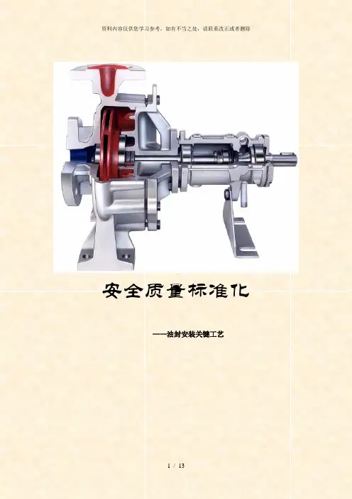
安全质量标准化——油封安装关键工艺骨架油封结构示意图名称各部位的作用①唇部唇端面(滑动面)唇端部是斜楔形状,在端部处按压轴表面,起到密封流体的作用。
②密封唇部密封唇是柔性弹性体,是对机械的振动及密封流体的压力变动的影响下仍可保持稳定的密封作用的设计,并起到保持唇部与轴表面接触状态,为稳定状态的作用。
另外弹簧可提高密封唇向轴的迫紧力,起维持此迫紧力的作用。
③防尘唇是没有与弹簧连接的副唇,起防止尘埃侵入的作用.防尘唇部④配合部配合部是油封在腔体孔内固定的同时,起防止流体从油封外周面与腔体内面的接触面间泄漏及侵入的作用。
另外金属骨架是当油封固定在腔体内时,起保持配合力的作用。
1、油封使用前保管要求1 不要打开原包装,注意包装是否损坏,装配前尽量把油封留在原包装里;2 避免日光直晒,也不要放置在高温热源附近,因为这会促使橡胶老化;3 油封不得随意散放,要注意防尘和防土,不要与化学品混放,确保使油封处在封闭或有盖状态;4 在运输和使用油封时,为防止油封变形和弹簧脱落,请不要给与过分冲击;5 油封不能用细绳捆扎,也不要挂在钉子或金属线上,这样会损伤密封唇;6 不得把油封放到潮湿的地方,这样会使金属部件生锈;7 不要将油封放在靠近电视和产生臭氧的地方;8 请不要用指甲或硬物摩擦唇口端部,以防损坏密封唇;2、轴、腔体的保护在装配前请不要使轴及腔体受到损伤,而引起泄漏,最好不要使精加工的轴与腔体碰撞到其他零件,请使用搬运夹具,如下例所示。
下图是搬运腔体用夹具,每一个腔体放入一个间隔中靠在壁上,不会损伤腔体孔,这种夹具的材质采用不会损伤金属的塑料(树脂).腔体的搬运夹具下图是轴用搬运夹具,使用塑料(树脂)罩防止轴损伤.轴的搬运夹具3、装配轴表面检查及主要参数确认表1:轴导入导角轴直径d1d1-d2轴直径d1d1—d2d 1≤10 1.5 50<d1≤70 4。
010<d1≤20 2。
0 70<d1≤95 4.520<d1≤30 2。
DRY GAS SEAL SYSTEM DESIGN STANDARDS FOR CENTRIFUGALCOMPRESSOR APPLICATIONSJohn StahleyDresser-Rand, Turbo Products, Olean, NY, USAThis paper will propose a set of gas seal support system design standards for process gas centrifugal compressors on the basis of safety, reliability, and economics.ABSTRACTDry gas seals have been applied in process gas centrifugal compressors for over 20 years. Over 80 percent of centrifugal gas compressors manufactured today are equipped with dry gas seals.Despite the twenty-year trend of increasing dry gas seal applications, an industry accepted standard for gas seal support system design does not exist. The American Petroleum Institute (API) has only recently addressed gas seal system design in its Standard 614 (1999). This paper will propose a set of gas seal system design standards for process gas centrifugal compressors on the basis of safety, reliability, and economics.This paper will present the philosophy of one centrifugal compressor and dry gas seal original equipment manufacturer (OEM) in regards to gas seal system design standards. These standards are based on over twenty years of experience in the area of gas seal system design, drawing from actual field experience of thousands of compressors. The reader shall recognize, however, that numerous gas seal system design philosophies can be applied to achieve the same system objectives.INTRODUCTIONDry Gas SealsDry gas seals are available in a variety of configurations, but the "tandem" style seal (Fig. 1) is typically applied in process gas service and is the basis for this paper. Other types of gas seals (such as double opposed) are not considered. Tandem seals consist of a primary seal and a secondary seal, contained within a single cartridge. During normal operation, the primary seal absorbs the total pressure drop to the user's vent system, and the secondary seal serves as a backup should the primary seal fail.Dry gas seals are basically mechanical face seals, consisting of a mating (rotating) ring and a primary (stationary) ring (Fig. 2). During operation, grooves in the mating ring (Fig. 3) generate a fluid-dynamic force causing the primary ring to separate from the mating ring creating a "running gap" between the two rings. Inboard of the dry gas seal is the inner labyrinth seal, which separates the process gas from the gas seal. A sealing gas is injected between the inner labyrinth seal and the gas seal, providing the working fluid for the running gap and the seal between the atmosphere or flare system and the compressor internal process gas.Barrier SealsOutboard of the dry gas seal is a barrier seal, which separates the gas seal from the compressor shaft bearings (Fig. 1). A separation gas (typically nitrogen or air) is injected into the barrier seals. The primary function of the barrier seal is the prevention of lube oil migration into the gas seal. The barrier seal also serves as the last defense in the event of a catastrophic failure of the primary and secondary gas seal. Traditional labyrinth seals or segmented carbon ring seals are used in most barrier seal applications today. Segmented carbon ring barrier seals offer the advantage of substantially lower separation gas flow requirements due to the larger shaft clearance associated with labyrinth seals. The author has previously presented a more detailed comparison of segmented carbon ring versus labyrinth barrier seals (Stahley, 2001).Gas Seal Support SystemsThe use of dry gas seals requires a support system, which is normally supplied by the centrifugal compressor OEM mounted adjacent to the compressor. The purpose of the gas seal system is as follows:·To provide clean, dry sealing gas to the faces of the dry gas seals.·To provide clean, dry separation gas to the barrier seals.·To monitor the "health" of the dry gas seals and barrier seals.SEAL GAS SUPPLYSourceThe end user must provide a source of seal gas supply to the compressor OEM's gas seal system. The seal gas source must be available at sufficient pressure to cover the entire operating range of the compressor including transient conditions such as startup, shutdown, or idle, and all static conditions. The seal gas should be at least 50 psi above the required sealing pressure at the customer connection point on the gas seal system in order to allow adequate regulation of the seal gas. If the primary source of seal gas does not meet this requirement, an alternate gas source or gas pressure boosting equipment will be required. It is very common in the industry to source the seal gas directly from the compressor discharge. The author has previouslydiscussed various implications of this approach (Stahley,2001).Another concern is the quality and composition of theseal gas. The seal gas should be free of solid particles 10microns and larger and 99.97 percent liquid free at thecustomer connection point on the gas seal system. It isalso critically important to assess the potential for liquidcondensation within the gas seal system or the gas sealsthemselves. To avoid such condensation, API 614 (1999)requires that the seal gas temperature into the gas seal be at least 20 °F above its dew point. This is a good rule ofthumb, but may not be sufficient in some cases.Consider an example of a hydrocarbon gascompressor with a required sealing pressure of 1,000psia. Sealing gas is process (hydrocarbon) gas, suppliedto the customer connection point on the gas seal systemat 1,050 psia. As the sealing gas flows through the gasseal system, through the primary gas seal, and finally tothe primary vent, the pressure will drop to nearlyatmospheric. A corresponding decrease in gastemperature will result from the Joule-Thomson effect. Aphase diagram for the hydrocarbon gas (Fig. 4) indicatesthe dew point for the seal gas at 1,050 psia is about 100°F. Following the API 614 (1999) recommendation of 20°F superheat would require the sealing gas to be heated to 120 °F at the customer connection point. However, acomputer simulation of the seal gas pressure andtemperature drops expected throughout the gas sealsystem reveals that the seal gas will pass through the mixed (gas and liquid) phase even with 20 °F superheat (Fig. 4). Further computer simulation indicates that, in order to maintain a 20 °F margin above the seal gas dew point throughout the entire gas seal system, the seal gas would need to be heated to 200 °F (i.e. 100 °F superheat) at the customer connection point (Fig. 4).To properly evaluate potential liquid condensation, acomputer simulation of the gas seal system, from thecustomer connection point to the primary seal vent, must be conducted during the system design phase. A 20 °F margin above the seal gas dew point should be maintained throughout the entire gas seal system. The computer simulation will determine the level of seal gas superheating required to meet this criterion. Depending on the quality of the seal gas and the result of the system simulation, special liquid separation and filtration equipment, and possibly heating of the sealing gas, may be required. Seal gas lines should be heat traced if ambient temperatures can fall below the dew point of the seal gas.FiltrationSeal gas filters immediately follow the customer connection point on the gas seal system. These filters should be used as "final" or "last chance" filtration and require compliance with the gas quality requirements explained in the previous section for maximum reliability. Duplex filter assemblies should be employed and provided with a transfer valve allowing filter element replacement while in service. The filter housing should be stainless steel, as required by API 614 (1999).Since the running gap between the primary and mating rings of most gas seals is about three to five microns, it is recommended that filter elements be capable of at least three micron (absolute) filtration. API 614 (1999) requires the use of coalescing filter elements under certain conditions. It is recommended here that, in anticipation of a possible liquid presence, coalescing filter elements be provided for all applications. API 614 (1999) requires some type of automatic liquid drainage of the filter housing when coalescing filters are employed. An alternative, more economical approach is to equip each filter housing with a manual liquid drain valve. The user's operational procedures should include, as part of the compressor operator's daily routine, the inspection of the filter elements and removal of any accumulated liquids as required. If the seal gas quality conforms to the requirements explained previously, liquid accumulation at the filters should be minimal during normal operation.The duplex seal gas filter assembly should be provided with a differential pressure gage and a high differential pressure alarm to indicate when the filter element has become fouled and needs to be replaced. The filter manufacturer normally advises a differential pressure at which the filter element should be considered no longer useful and therefore replaced with a new element. The high differential pressure alarm should be set accordingly. A pressure gage should also be provided upstream of the filter assembly to indicate the seal gas supply pressure (Fig. 5).ControlThere are two basic methods of controlling the supply of sealing gas to the gas seals - differential pressure (D P) control and flow control. D P systems control the supply of seal gas to the seal by regulating the seal gas pressure to a predetermined value (typically 10 psi) above a referenced sealing pressure. This is accomplished through the use of a differential pressure control valve (Fig. 6).Flow control systems control the supply of seal gas to the seal by regulating the seal gas flow through an orifice upstream of each seal. This can be accomplished with simple needle valves or, when automatic control is desired, through the use of a differential pressure control valve monitoring pressures on either side of the orifices (Fig. 7). Automatic control is recommended.The primary objective of the seal gas control system is to assure that sealing gas is injected between the inner labyrinth seal and the gas seal at a rate sufficient to prevent reverse flow of unfiltered process gas across the inner labyrinth seal and into the gas seal. A flow rate of 16 ft/s is an industry accepted standard for sealing with labyrinth seals. This is considered the minimum acceptable seal gas velocity for gas seal applications. Therefore, in order to assure a positive flow of seal gas across the inner labyrinth seal, gas seal systems should be designed to provide a minimum gas velocity of 16 ft/s across the inner labyrinth seal at all times. The seal gas velocity across the inner labyrinth seal will vary with labyrinth clearance. In order to maintain the minimum 16 ft/s velocity across the inner labyrinth seal at increased labyrinth clearance, the system should be designed to provide twice the seal gas velocity (i.e. 32 ft/s) at design inner labyrinth clearance. This is a conservative approach to system design that allows for increasing labyrinth clearance that may result from normal operating wear of the labyrinth seal.It is also desirable to minimize seal gas consumption. The majority of the injected seal gas flows across the inner labyrinth seal and back into the compressor, and very little flow is actually required for the gas seal. This "recycled" flow into the compressor is inefficient and uses more energy at a cost to the user. Unnecessarily high seal gas flow can also result in increased initial gas seal system costs, since the high flow can result in larger sized, and thus more expensive, gas seal system components such as filters, valves, piping, etc. This added expense becomes even more significant if special liquid separation and/or filtration equipment is required due to unacceptable seal gas quality.In order to achieve the minimum seal gas velocity of 32 ft/s across the inner labyrinth seal, and to minimize the amount of seal gas consumed, flow control is recommended over D P control systems. Since flow control systems are set to maintain the flow of seal gas supply through an orifice, the supply mass flow rate is constant and will not vary with labyrinth clearance.To demonstrate the advantages of flow control over D P control systems, consider the following example. Using a 25 mole weight hydrocarbon mixture, a chart was constructed depicting the sealing gas mass flow, velocity, and differential pressure across the inner labyrinth seal for a range of sealing pressures using both flow control and D P control systems (Fig. 8). The data for the D P control system is based on a seal gas supply pressure of 10 psi over the reference pressure. The data for the flow control system is based on a constant seal gas velocity of 32 ft/s across the inner labyrinth seal.As can be seen from the chart (Fig. 8), the sealing gas mass flow and velocity across the inner labyrinth seal are equivalent for flow control and D P control systems at a sealing pressure of about 2,900 psi. At sealing pressures less than 2,900 psi, the sealing gas mass flow for D P control is much higher than that of flow control at the same sealing pressure. For example, at a sealing pressure of 1,000 psi, D P control uses about 70 percent more seal gas (mass flow) than flow control. As explained previously, the excess flow consumed by the D P control system is inefficient and uneconomical, and the use of flow control is recommended.At sealing pressures greater than 2,900 psi, the amount of sealing gas consumed by the flow control system is actually greater than that of D P control at the same sealing pressure. However, the velocity of the sealing gas across the inner labyrinth seal drops below the minimum recommended value of 32 ft/s when using D P control at these higher pressures. This increases the possibility of gas seal contamination from unfiltered process gas and therefore is a threat to gas seal reliability. For this reason, the use of flow control is again recommended.The relationships between sealing gas mass flow and velocity across the inner labyrinth seal for flow control and D P control systems demonstrated above hold true for all types of process gases, shaft sizes, and labyrinth clearances. For gases of different mole weights, the sealing pressure at which the two types of control systems have equivalent sealing gas mass flows and velocities simply changes inversely proportional to the change in mole weight. For example, for a 40 mole weight gas, constructing a similar chart (Fig. 9) of sealing pressures using the same assumptions as the previous 25 mole weight example, it can be seen that the equivalent pressure is about 1,800 psi, as compared to 2,900 psi for the 25 mole weight gas. For lower mole weight gases, the equivalent pressure increases. Constructing yet anotherchart (Fig. 10) for a five mole weight gas indicates that the equivalent pressure is "off-the-chart" and beyond the sealing pressure capability of today's gas seal technology.As can be seen from the three charts of various mole weights and sealing pressures, the differential pressure across the inner labyrinth seal can become quite low when using a flow control system at lower sealing pressures (relative to the equivalent pressure). Low differential pressures across this labyrinth could be susceptible to process upsets, increasing the possibility of gas seal contamination from unfiltered process gas and threatening gas seal reliability. To compensate for this condition, it is recommended that the flow control system be designed to maintain a minimum three psi differential pressure across the inner labyrinth seal. This will increase the seal gas consumption and velocity across the inner labyrinth seal accordingly.As demonstrated above, flow control systems have definite advantages over D P control systems, and flow control is therefore recommended. The gas seal system should be designed to provide a minimum gas velocity of 32 ft/s and a minimum differential pressure of three psi across the inner labyrinth seal at design labyrinth clearance. The application of these criteria will assure a positive flow of sealing gas across the inner labyrinth seal, reduce the risk of gas seal contamination from the process gas, thereby adding to increased gas seal reliability. The use of flow control also has the added advantage of eliminating the need for measurement of the reference (sealing) pressure from a cavity internal to the compressor, which is required when using D P control systems. Accurate reference pressure measurement can be difficult in some instances as has been discussed in detail by the author (Stahley, 2001).The flow control system should include a "high-select" feature for the reference pressure (low pressure, downstream) side of the orifices (Fig. 7). The high select feature includes reference lines on the downstream side of the orifices in the seal gas supply piping to both gas seals. These lines include check valves to prevent cross flow of seal gas from each end of the compressor and are tied together into a single line before connecting to the differential pressure control valve. This allows the system to seal against the "worst case" (highest reference pressure) condition in the event that the seal gas flows required by each gas seal are slightly different. The check valves are drilled through to allow bleeding off of the built up pressure. The system should also include a pressure gage downstream of the control valve to indicate the seal gas supply pressure and instrumentation to initiate an alarm when the differential pressure across the orifices falls below a predetermined value.PRIMARY GAS SEAL VENTSealing gas is injected between the inner labyrinth seal and the gas seal (Fig. 1). The vast majority of this injected gas flows across the inner labyrinth seal and into the compressor, or "process" side of the gas seal. A very small amount of the sealing gas passes through the primary seal and out the primary vent, which is normally connected to the user's flare system. The gas seal manufacturer determines the gas seal leakage rate to the primary vent based on the specified service conditions and seal design. Leakage rates are typically between five and 15 scfm depending on seal size and service conditions.The primary vent can be fabricated from carbon steel piping. The vent should be equipped with a valved, low point drain to allow removal of any built-up liquids in the primary vent area that could cause damage to the primary seal (Fig. 11). If the primary vent is connected to a flare system, a check valve must be included to prevent any potential reverse flow from the flare system into the primary vent area, which could cause damage to the gas seal.Primary Gas Seal HealthThe suggested method of assessment of the condition of the dry gas seal is by monitoring the gas seal leakage through the primary vent. This is accomplished by measuring the flow or pressure across a restriction orifice in the primary vent piping. An increasing flow or pressure trend is indicative of increasing gas seal leakage and suggests deterioration of the primary seal. The flow restriction orifice (FE in Fig. 11) should be provided with a differential pressure transmitter to monitor and record seal leakage trends. An alarm should be included to initiate upon increasing pressure or flow above a predetermined limit. The recommended alarm level varies depending on the gas seal manufacturer, but twice the calculated gas seal leakage rate is a conservative approach.Safety IssuesThe primary vent system must be designed to cope with a total failure of the primary seal. It is highly recommended that a shutdown and depressurization ofthe compressor be initiated upon the failure of the primary seal. The secondary seal is intended to act as a backup in case of primary seal failure, providing the necessary shaft sealing until the compressor can be safely shut down and depressurized. Due to increased safety risks, operation on the secondary seal for extended periods of time is strongly discouraged.A pressure sensing device, installed upstream of the flow orifice, should be used to initiate a shutdown and depressurization of the compressor upon increasing pressure above a predetermined limit. Again, the recommended shutdown level varies depending on the gas seal manufacturer, but three times the calculated gas seal leakage rate is a conservative approach.In the event of a catastrophic failure of the primary seal, the primary vent is subject to a much higher gas flow, causing a backpressure in the piping upstream of the flow restriction orifice. A rupture disc should be installed in the primary vent to relieve the backpressure and evacuate the gas. The rupture disc (PSE in Fig. 11), installed in parallel to the primary vent flow orifice, should be designed to burst at about 20 psi differential (depending on normal flare system design pressure). It should be noted that the high differential pressure or flow alarm and shutdown limits would be exceeded before the rupture disc will burst.Before the compressor can be restarted after the gas seal has been repaired or replaced, a new rupture disc must be installed. It must be recognized that it is physically possible to restart the compressor with the damaged rupture disc in place. If this is allowed to occur, the instrumentation installed in the primary vent to initiate an alarm or shutdown will be rendered ineffective. The primary seal gas leakage will flow unobstructed through the void created by the burst rupture disc and a high flow or pressure will not be detected by the instrumentation. The user must be aware of these circumstances and maintenance procedures must be established accordingly.To avoid this potential safety issue, the rupture disc should be fitted with an electronic continuity detector to indicate the disc has failed, thereby alerting the operator to avoid further startup attempts. Or, the electronic device can be connected into the start control system to prevent startup if the rupture disc has not been replaced. Another, less economical alternative is to use a relief valve in place of the rupture disc. However, the reader is cautioned to note the difficulties in sizing a relief valve for high flow, low differential pressure applications.SEPARATION GAS SUPPLY TO THE BARRIER SEALSourceThe end user must provide a source of separation gas supply to the compressor OEM's gas seal system (Fig.12). The separation gas is required for the barrier seals, which are intended to prohibit lube oil migration into the gas seal. The separation gas is fed to the barrier seals through stainless steel tubing. The separation gas must be available at sufficient pressure as defined by the barrier seal manufacturer with enough margin to account for buildup of pressure drop through the gas seal system components. It is very common to use instrument air as the separation gas medium. This requires careful attention to safety considerations, which will be discussed later. It is highly preferable to use nitrogen as the separation gas medium.Compared to the main seal gas supply, the quality and composition of the separation gas is of lesser concern. Barrier seal tolerances are not as small as gas seal tolerances, and therefore the gas quality requirements are less stringent. However, the typical sources of separation gas (nitrogen or instrument air) are generally very clean in comparison to seal gas sources. Therefore, the separation gas "requirement" at the customer connection point on the gas seal system is that it be free of solid particles 5 microns and larger and 99.97 percent liquid free.FiltrationA separation gas filter immediately follows the customer connection point on the gas seal system. This is again intended as "final" or "last chance" filtration assuming compliance with the gas quality requirements explained in the previous section. API 614 (1999) requires a duplex filter arrangement, but a single filter element with stainless steel housing has been proven to be adequate for this service. The filter should include a bypass line allowing filter element replacement while in service.Since, as mentioned previously, the typical sources of separation gas are generally very clean, it is recommended that filter element be capable of five micron (absolute) filtration. Coalescing filter elements and manual drain valves should be provided for all applications.The separation gas filter assembly should be provided with a differential pressure gage and a high differential pressure alarm to indicate when the filterelement has become fouled and should be replaced. A pressure gage should also be provided upstream of the filter assembly to indicate the separation gas supply pressure (Fig. 12).ControlThe supply of separation gas to the barrier seals should be controlled using a differential pressure (D P) control system. Approximately equal parts of the separation gas will flow through the barrier seal into the compressor bearing chamber (outboard side), and into the secondary seal vent area (inboard side). The D P system controls the supply of separation gas to the barrier seals by regulating the separation gas pressure to a predetermined value above the secondary vent pressure. This is accomplished with a differential pressure regulator.The barrier seal manufacturer determines the required separation gas pressure to the barrier seal. Typical pressure requirements are three to five psi differential for labyrinth barrier seals and five to 10 psi differential above the secondary vent area pressure for carbon ring barrier seals. The separation gas supply tubing should include a gage to indicate the differential pressure between the gas supply and the secondary vent. It is important to note that the reliability and length of service of the barrier seal can be greatly influenced by the absolute value of the separation gas pressure. The design of the system must take into consideration the maximum pressure that can be accepted by the barrier seal without creating abnormal wear of the seal itself. The barrier seal manufacturer must provide the maximum pressure vs. seal life characteristic.It is vitally important to the reliability of the barrier seals and gas seals that lube oil is only supplied to the compressor bearings when proper separation gas pressure exists. This can be assured with the following controls (Fig. 13):·An alarm is required if the differential pressure between the separation gas supply and the secondary vent falls below a predetermined level.·If proper separation gas pressure is lost during operation (rotation) of the compressor, a delayed shutdown is recommended. If low separation gas differential pressure is detected, a shutdown should be initiated after about 30 minutes. This will give operators time to attempt to reestablish proper separation gas supply and minimize the effects of oil migration to the gas seals. When compressor shaftrotation has come to a complete stop, lube oil flow to the bearings must be halted. If this is not possible due to turning gear requirements or for concern of heat soak into the bearings, an emergency nitrogen supply must be supplied to provide the required sealing during these conditions.·If proper separation gas pressure is lost while the compressor is static (not rotating), lube oil flow to the bearings must be immediately halted.·Proper separation gas pressure must be confirmed before proceeding to provide lube oil flow to the bearings. A "permissive - start" the lube oil pumps is required.SECONDARY GAS SEAL VENTReviewing overall seal operation, sealing gas is injected between the inner labyrinth seal and the gas seal.A very small amount of the sealing gas passes through the primary seal and out the primary vent. An even smaller amount (typically less than 0.1 scfm) of sealing gas passes through the secondary seal and out the secondary vent. The majority of the flow through the secondary vent is separation gas which has passed through the barrier seal (Fig. 1).The secondary vent can be fabricated from carbon steel piping. The vent system should be equipped with a valved drain at its lowest point to allow removal of any potential lube oil carryover from the bearings. The secondary vent should be vented to atmosphere. If the secondary vent is connected to a flare system, a check valve must be installed to prevent any potential backflow into the vent, which could cause damage to the secondary gas seal and/or barrier seal. The system design must also consider the possible increased flow to the compressor bearing housing and/or coupling guard area to avoid interfering with the normal venting of these areas from too high a pressure supplied to the barrier seal. Secondary Gas Seal HealthIt is difficult to monitor the health of the secondary seal. Unlike the primary seal vent, a flow or pressure measurement of the secondary vent is of little value for assessing the health of the secondary seal. Since the vast majority of the gas flow through the secondary vent is injected separation gas, measurement of this flow is not representative of secondary seal performance.As explained by the author (Stahley, 2001), the biggest threat to the reliability of the secondary seal is contamination from bearing lube oil. Therefore, an。

操作手册本文件按EC directives“MACHINERY”(EN292-2)和德国标准VDI4500编制BURGMANN 机械密封(M.S.)干气密封PDGS2/108-ZT1-RPDGS2/108-ZT1-L本说明书供安装、操作和控制人员使用,在现场应随身携带。
请仔细阅读本手册并遵守以下各节中所述内容:安全贮存安装试运维护拆卸修理如有不详之处请随时与BURGMANN联系。
目录总安全说明特殊安全措施关于产品的资料制造厂和产地制造厂说明指定型号操作条件指定用途图表说明及功能要求空间,连接尺寸机械密封的供应废气排放气体量版权运输/贮存/安装运输包装和贮存组装准备推荐的设施和工具组装/安装提供的接头操作推荐的工艺介质试运说明安全操作说明故障处理指南服务建议预期寿命修改DGS在仓库中的保存运行中的DGS服务维护BURGMANN 干气密封的修理BURGMANN 的售后服务解体/拆卸备件询价和订单的要求细节BURGMANN机械密封的处理总安全说明参加组装、解体、试运、操作和维护BURGMANN机械密封的所有人员必须阅读和了解本说明手册,特别是安全注释。
我们建议用户确保作到这一点。
BURGMANN机械密封以高质量水准(ISO9001)制造,具有高的质量稳定性。
然而,如果不在其指定用途下操作或由未经训练的人员进行非专业的处理,则可能产生故障。
作为其安全程序的一部分,要求用户检查因机械密封的失效可能对环境产生的影响,以及进一步采取何种安全措施以防止人员伤亡。
任何影响机械密封操作安全的操作模式都是不允许的。
BURGMANN机械密封必须由授权的、训练有素的、经过指导的人员进行操作、维护和修理。
仅在机械密封停运和无压力时方可对其进行修理。
必须明确相关工作的责任,以防止安全观点上的责任不清。
除本手册给出的说明以外,还必须遵守工人的防护和事故预防规定。
未经授权对机械密封进行修改和更换是不允许的,因其影响机械密封的运行寿命。

InstallationInstructions ISC2 SeriesInnovative Standard Cartridge seal designedfor general purpose applications.1 Equipment Check1.1 Follow plant safety regulations prior to equipment disassembly:1.1.1 Wear designated personal safety equipment1.1.2 Isolate equipment and relieve any pressure in the system1.1.3 Lock out equipment driver and valves1.1.4 Consult plant Safety Data Sheet (SDS) files for hazardous material regulations1.2 Disassemble equipment in accordance with the equipment manufacturer’s instructionsto allow access to seal installation area.1.3 Remove existing sealing arrangement (mechanical seal or otherwise).Clean seal chamber and shaft thoroughly.1.4 Inspect surfaces under gaskets to ensure they are free from pits or scratches. Break all sharpcorners on shaft steps, threads, reliefs, shoulders, key ways, etc. over which gasket(s) must pass and/or seal against.1.5 Check shaft or sleeve OD, seal chamber bore, seal chamber depth, gland pilot, stud diameter,stud bolt pattern and distance to first obstruction to ensure they are dimensionally the same as shown in the seal assembly drawing.1.6 Check seal assembly drawings for any modifications (reworks) to be made to the equipmentfor mechanical seal installation and act accordingly.1.7 The equipment must be earthed to prevent sparks due to static electricity discharge2Shaft runoutat any point along the shaft for ball or roller type bearings. For sleeve type bearings, refer to manufacturer instructions. If the equipment is not completely dismantled, verify runout near seal location.The above values apply to shaft speeds in the range from Flowserve representative. See Figure 1.Shaft endplayregardless of thrust bearing type. See Figure 2.Radial bearing play to verify the equipment’s suitability for the seal.Seal chamber squareness to the shaft centerline shouldbe within 0.0005 mm/mm (0.0005 inch/inch) of seal chamber bore TIR.Note: make sure that shaft endplay does not affect the reading. Verify the smoothness of the sealchamber face for a good gasket joint. See Figure 3.Concentricity of the shaft diameter (0.001 inch per 1 inch shaft diameter) to a maximum of 0.125 mm (0.005 inch) TIR. See Figure 4.+0.000 mm (+0.000 inch) API 610/682-0.025 mm (-0.001 inch) DIN/ISOSurface finish requirements32 ISC2 Seal InstallationNote: No seal setting measurements are needed to install the seal. Instructions are for end-suction back pull-out pumps. Modification of these procedures may be required for other style pumps. Consult Flowserve for installation support.DescriptionThis ISC2 seal is a versatile cartridge mounted mechanical seal, designed for ease of installation and reliable operation. No seal setting dimensions are required. Removable setting devices provide proper alignment.The ISC2 seal family consists of:ISC2-PX - Single pusher seal with stationary springs ISC2-PP - Dual pusher seal with stationary springs ISC2-BX - Single metal bellows seal with rotating bellows ISC2-BB - Dual metal bellows seal with rotating bellows ISC2-XP - Single pusher seal with a pumping device for a Plan 23 ISC2-XB - Single metal bellows seal with a pumping device for a Plan 23Figure 22.1Lubricate the shaft or pump sleeve lightly with silicone lubricant unless otherwise specified.2.2 Tighten the setting device cap screws to ensure they are tight before installation.2.3Slide the ISC2 seal cartridge onto the shaft or pump sleeve with the setting devices toward the bearing housing. See Figure 2.2.4Install the seal chamber and bolt it inplace on the bearing frame. See Figure 3.Figure 3Recommended ISC2 seal minimum set screw torque by size range: Seal mm 25 - 60 67 - 70 75 - 203 75 - 203Size (inch) (1.000 - 2.500) (2.625 - 2.750) (2.875 - 8.000) (2.875 - 8.000)Gland Size AllAllStandard Bore Enlarged Bore Torque 4.5 N-m 13.5 N-m 16.9 N-m 27.1 N-m(40 in-lbs) (120 in-lbs)(150 in-lbs)(240 in-lbs)4Figure 42.5 Position the ISC2 seal with the gland tight against the seal chamber.2.6 Orient the ISC2 seal with the ports aiming as shown on the seal assembly drawing. See Section 3 for Piping Recommendations.2.7Tighten the gland nuts evenly in a diagonal sequence. Do not over-tighten the gland nuts, as this can warp seal parts and cause leakage. Confirm adequate thread engagement before final torque setting.Recommended ISC2 seal minimum gland nut torque by size range:Seal mm 25 - 50 54 - 70 75 - 102 108 - 152 159 - 203 Size (inch) (1.000 - 2.000) (2.125 - 2.750) (2.875 - 4.000) (4.250 - 6.000) (6.250 - 8.000)Torque 20 N-m27 N-m 40 N-m47 N-m 54 N-m(15 ft-lbs) (20 ft-lbs) (30 ft-lbs) (35 ft-lbs) (40 ft-lbs)Note: Some equipment with small bore seal chambers provide limited access to the gland bolting and setting device cap screws. In some situations, the gland fasteners interfere with the setting devices and window access may require deviation from the standard fastening sequence. For example, the collar/sleeve assembly may need to be rotated slightly from its factory-set position by loosening the setting device cap screws, rotating the collar/sleeve assembly, then tightening the screws. When nonstandard processes are followed, be careful to maintain the integrity of the seal cartridge at all times.2.8Assemble the equipment per manufacturer specifications. Avoid pipe strain.Align the coupling permanufacturer specifications. 2.9With the impeller, shaft, coupling and bearings in their final operating position, tighten the drive collar set screws. See Figure 4.Note: in designs that have two smaller screws, these are quarter dog screws that hold the collar to the sleeve and should not betightened. A hex key was provided for the set screws, not for thequarter dog screws.2.10 Remove the setting devices fromscrews. See Figure 5. Save the settingdevices and fasteners for future usewhen the pump impeller is reset orwhen the seal is removed for repairs.2.11 Turn the shaft by hand to ensureunobstructed rotation.2.12 See Operational Recommendationsbefore start-up.3 Piping Recommendations3.1 Install and maintain an adequate piping plan. The ISC2 seal requires a clean, cool environmentfor maximum seal life. Typical piping plans are listed below. Contact Flowserve for additionalpiping plan information or technical support.Important: All red plastic caps/thread guards are for shipping protection only and should bereplaced with either a piping connection or a metal plug in the same metallurgy as the gland.Plan 02: d ead-ended seal chamber with no flush (single seals, always plug Flush port)Plan 03: c irculation created by the design of the seal chamber(single seals, always plug Flush port)Plan 11: default inner seal flush from pump discharge on horizontal pumps (single seals)Plan 13: d efault inner seal flush and vent from pump suction on vertical pumps (single sealsPlan 21: i nner seal flush from pump discharge through a cooler for use with hot products (single seals)Plan 23: i nner seal flush from internal pumping device through cooler(ISC2-XP and ISC2-XB designs)Plan 32: i nner seal clean external flush for use with abrasive products or products that are incompatible with the seal (single seals)Plan 52: d ual seal circulation through a low pressure reservoir (dual seals)Plan 53: d ual seal circulation through a pressurized reservoir (53A),finned tube array (53B) or piston accumulator (53C) (dual seals)Plan 62: e xternal quench on atmospheric side of seal (single seals)3.2 For dual seals, LBI (Liquid Barrier Inlet) and LBO (Liquid Barrier Outlet) are marked on thegland. ISC2 seals are unidirectional and piping the correct inlet and outlet is important toproper circulation. The liquid barrier inlet should draw from the bottom of the supportsystem while the liquid barrier outlet feeds the top of the system.53.3 For dual pressurized seal (Plan 53, double seal) operation, supply a clean, compatible barrierfluid at a pressure at least 1.7 bar (25 psi) above the seal chamber pressure. See Figure 6.The pressure of the barrier fluid must not exceed the recommended maximum pressure. Dual pressurized (Plan 53A) ISC2 with Supply Tank Figure 663.4 For dual unpressurized (Plan 52, tandem seal) operation, supply a clean, compatible bufferfluid at a pressure below the seal chamber pressure. The pressure in the seal chamber must not exceed the recommended maximum pressure.3.5 For single seal operation excluding Plan 23, ensure all ports are fitted with piping orplugs. Plans 02 and 03 must close the Flush port with a metal plug in the same metallurgy as the gland. If Plan 62 is not used, the Quench port should be plugged. The Drain port should be connected to a drain line to prevent leakage along the shaft. Note: the Quench and Drain ports are smaller than the flush port as a distinguishing feature.3.6 For single seal operation with Plan 23, FI (Flush Inlet) and FO (Flush Outlet) are markedon the gland. ISC2 seals are unidirectional and piping the correct inlet and outlet is important to proper circulation. The flush inlet should draw from the bottom of the cooler while the flushoutlet feeds the top of the cooler. Ensure piping is optimized for thermosyphon flow.4 Operational Recommendations4.1 Remove lock outs on equipment and valves.4.2 Do not start up the pump dry to check motor rotation or for any other reason. Open valves toflood pump with product fluid. Ensure that the seal flush or support system is operating. Ventair from the casing of the pump and the seal chamber before start-up.4.3 Observe the start-up. If the seal runs hot or squeals, check the seal flush system. Do not allowthe pump to run for any extended time if the seal gets hot or squeals.4.4 Do not exceed corrosion limits. The ISC2 seal is designed to resist corrosion through propermaterial selection. Do not expose the ISC2 seal materials of construction to products outside of their corrosion limits. Consult Flowserve for chemical resistance recommendations.4.5 Do not exceed pressure and speed limits established for the ISC2 seal.4.6 Do not exceed the temperature limits of the ISC2 seal based on the materials of construction.For dual seals using supply tanks with cooling coils, turn on cooling water to the supply tankbefore start-up.4.7 Do not start up or run the ISC2 seal dry. The seal chamber, pump and support systems shouldbe thoroughly vented before start-up. Buffer or barrier fluid must flood the seal cavity of dualseals at all times during operation. Process fluid must be in the seal chamber at all times during single seal operation.5 RepairsThis product is a precision sealing device. The design and dimension tolerances are critical to seal performance. Only parts supplied by Flowserve should be used to repair a seal.To order replacement parts, refer to the part code and B/M number. A spare backup seal should be stocked to reduce repair time.When seals are returned to Flowserve for repair, decontaminate the seal assembly and includean order marked "Repair or Replace." A signed certificate of decontamination must be attached.A Safety Data Sheet (SDS) must be enclosed for any product that came in contact with the seal.The seal assembly will be inspected and, if repairable, it will be rebuilt, tested, and returned.The images of parts shown in these instructions may differ visually from the actualparts due to manufacturing processes that do not affect the part function or quality.7FIS190eng REV 09/2018 Printed in USATo find your local Flowserve representativeand find out more about Flowserve Corporation,visit Flowserve Corporation has established industry leadership in the design and manufacture of its products. When properly selected, this Flowserve product is designed to perform its intended function safely during its useful life. However, the purchaser or user of Flowserve products should be aware that Flowserve products might be used in numerous applications under a wide variety of industrial service conditions. Although Flowserve can provide general guidelines, it cannot provide specific data and warnings for all possible applications. The purchaser/user must therefore assume the ultimate responsibility for the proper sizing and selection, installation, operation, and maintenance of Flowserve products. The purchaser/user should read and understand the Installation Instructions included with the product, and train its employees and contractors in the safe use of Flowserve products in connection with the specific application. While the information and specifications contained in this literature are believed to be accurate, they are supplied for informative purposes only and should not be considered certified or as a guarantee of satisfactory results by reliance thereon. Nothing contained herein is to be construed as a warranty or guarantee, express or implied, regarding any matter with respect to this product. Because Flowserve is continually improving and upgrading its product design, the specifications, dimensions and information contained herein are subject to change without notice. Should any question arise concerning these provisions, the purchaser/user should contact Flowserve Corporation at any one of its worldwide operations or offices.© 2016 Flowserve Corporation USA and Canada Kalamazoo, Michigan USA Telephone: 1 269 381 2650 Telefax: 1 269 382 8726Europe, Middle East, Africa Etten-Leur, the Netherlands Telephone: 31 765 028 200 Telefax: 31 765 028 487Asia PacificSingapore Telephone: 65 6544 6800 Telefax: 65 6214 0541Latin AmericaMexico City Telephone: 52 55 5567 7170 Telefax: 52 55 5567 4224TO REORDER REFER TO B/M #F.O.。
Ecopaint SealingVehicle Sealing – efficient and flexible»»Hem flange applicationEcopaint Sealing –cuStomer-Specific SolutionS for Vehicle Sealingecopaint Sealing –Dürr’s product family for the automated sealing and preservation of car bodies.High viscosity sprayable materials such as PVC plastisols are used for sealing to protect car bodies against corrosion and water ingress. The innovative Dürr ecopaint Sealing system product range is based on , and thus improves economic efficiency and guarantees highest quality and environmental compatibility. The system covers all dimensions of efficiency, through which Dürr supports its customers in the production process.This reliably reduces unit costs – with the highest quality.reduction of unit costs»»Seam sealingAutomation reduces the scope of manual application.Dürr counts on efficiency and even reduces materialconsumption through a more accurate and reproduc-ible process control.maximum qualityDürr application systems guarantee a reproducibleprocess control and thus consistent product quality.Through optimized processes manual touch-ups canbe avoided.highest environmental compatibilityHigh quality and automated process controls re d ucematerial consumption and conserve resources.23process efficiency for all areas of applicationDürr offers modularly designed systems for all uses in application on the car body according to specific customer specifications:1. Seam sealingThe sealing material is applied to overlapping sheet metals on car bodies to avoid gap corrosion due to intruding water. 2. underbody coatingIn order to counteract wear in the underbody area from stone-chipping and similar effects, an underbody sealer is applied. It is mainly applied in wheel wells or rocker panel areas just prior to the primer spray booth.3. rocker coatingThe surface of vehicle rocker panels is coated to protect against stone-chipping by means of a fully automatedspecific masking technique. This way, the required coating with high edge definition in the upper area of the rocker panels is achieved.4. hem flange applicationsHem flanges on add-on pieces for the car body, such as doors, hoods or tailgates, are sealed with a highly precise Dürr application system in connection with specific nozzle technology. As a result, it is not necessary to open doors or tailgates for the purpose of improved accessibility. The application quality meets requirements for visible welds. 5. Spraying insulantsFor cost and flexibility reasons, manually used sound dampening mats are replaced by sprayable material that is applied increasingly by robots. The sound insulating material is applied with a nozzle technology that is espe-cially designed for this purpose.Optimumproduction useQualityimprovement Risk minimizationReduction of expenditures for installation and commissioning planningModelSimulationProcesssafeguardingEcopaint testcenter SealingCross checkprecommis-sioningRealizationproduction6. cavity preservationWith a wax film, the cavities of the car body are protected against corrosion. For optimum protection with minimum material usage, the wax is applied in corrosion-pronea reas by robot-guided lances and injection nozzles. 7. covering window flangesCovering window flanges with a strip-off layer of PVC plastisol before spraying prevents paint overspray build up. After painting, the material is removed and the wind-shield can be glued to the clean electro primed window flange.from planning to realizationAs a supplier of turnkey plants, Dürr is well known for comprehensive process knowledge and high-quality prod-ucts. More than 1000 robot installations have been carried out successfully in recent years. Automation with robots guarantees a high level of model flexibility and maximum application quality. The application scope and body shape determine the arrangement of the robots. In addition, simulations, application tests, and pre-commissioning procedures before delivery provide the basis for fastproduction optimization. Dürr is a reliable and experienced partner for all phases of project execution and customer service after production commences. For our customers this means efficient and custom solutions from A to Z.Eco r S – efficient robotic technologyWith the standard eco R S robot, Dürr responds to car man-ufacturer requirements of homogeneous and economical technologies for the entire sealing area.Efficient and flexible: The robots, in various sizes and loads, are selected according to job definition and exact require-ments. The Dürr eco R PC robot controller integrates move-ment and process control on one platform. This reduces communication times – which occur with non-integrated systems – and facilitates a homogeneous operating concept for movement and process. A uniform arrangement of the man-machine interface, in both the sealing and painting processes, facilitates the operation and maintenance of robots across the entire paint shop.Eco r ail – flexible applications with movable robotsFor the best possible usage and to increase working space, eco R ail extended axes are used. The eco R ail is a freely programmable, horizontal movement axis for all sealing applications. The eco R ail extended axis is available in various lengths and designs – depending on customer and/or process requirement.Ecopaint Sealing – robot StationS for all application proceSSeSfor all application processes5Eco r pc – dürr’s integrated robot and process controllereco R PC – the Dürr controller is used both for sealing and coating processes.»Multikinematics / multiprocess capability with up to four movement / process units»Integrated PLC system for easy adaptationand diagnosis of process and automation functions »Easy maintenanceEco Screen 3d-onSiteeco Screen 3D-OnSite is a 3D visu-alization and programming soft-ware developed by Dürr which was designed for the production andprocessing of robot programs as well as the parameterization of corre-sponding process data. In this way, an optimal installation operation tool is available to the customer directly at the robot cell in production.the use of Eco Screen3d-onSite provides thef ollowing advantages: »Change of path and process para-meters possible online and offline »Online parameterization during production allows increased production quality with reduced downtime»3D robot cell and car body model »Extensive simulation functions»»Eco Dose PCL7Eco Shot meter double –great dynamics in the processWith the eco Shot Meter Double electrical double dosing de-vice, material is dosed continuously and extremely precise-ly. The system is suitable for applications that require great dynamics and high accuracy in the process. Control of thedouble dosing device is fully integrated into the eco RPC and facilitates the application of a continuous bead. Dürr’s hose expansion compensation software reduces the reac-tion times of the dosing system.»»Eco Gun Sealing 3D»»Eco Gun Sealing IDS9Eco g un Sealing md – masking deviceeco G un Sealing MD is employed in areas where coating with high edge definition is necessary. In automobileproduction this application is normally used in the rocker panel area. When the eco G un Sealing MD is used, masking of the rocker panel is not necessary to obtain a high edge definition.Eco Jet – high quality nozzles with continuous performanceDiverse sealing applications require various nozzles which must live up to their demands. Dürr has developed suitable nozzles based on for each application, and constantly expands their product range. Nozzles for airless, flat stream, round, swirl, extrusion, LASD and hem flange applications are available. The nozzles are charac-terized by constant application quality and a long life cycle. For quality assurance, tests on the nozzle test status are carried out. This ensures the reproducibility of the applica-tion – even after a nozzle change.Ecopaint Sealing – programming, cleaning and conditioning cleaning and conditioningEco g un Sealing – easy handlingthanks to its laser programming aidThe laser programming aid for the eco G un Sealing utilizes optical simulation of the material stream and thus sup-ports in the programming of the robot. The laser simulates the representation of the material application points.The laser programming aid simplifies programming through the following characteristics:»Switching on and off the laser head by means of the robot controller conforming to the beginning and endof the seam»Seat is identical to nozzle, therefore requiring lowi nstallation effort Eco g un Sealing cleaner –clean results through nozzle cleaningThe eco G un Sealing Cleaner cleans the nozzles of the applicator. Air nozzles blow off any material sticking to the application nozzles. The air nozzle position and height are adjustable, giving the eco G un Sealing Cleaner flexibility in various applications.An accumulation vessel collects the blown off material.This avoids:»Soiling of the car body and the booth»Manual cleaning»Cycle time losses in the finishing area, since manual cleaning work at the robot is eliminatedEco temp und Eco h eat – conditioning of material for stable application resultsTemperature conditioning of the application material guarantees stable application results. Material charac-teristics are maintained by use of cooling and / or heating. The resulting constant material viscosity in combination with volume controlled dosing system produces the high-est quality application.The following systems are used for the conditioningof materials:»eco H eat:Electrical material heating for the temperature range of 32 - 45 °C»eco Temp:Water-based temperature conditioning for the temperature range of 20 - 32 ° C, or Peltier temperature conditioning for the temperature range of 25 - 38 ° C. Both systems are used for the underbody sealing process, rocker coating, LASD (liquid applied sound deadener), and in seam sealing.1011Ecopaint testcenter SealingEcopaint Testcenter SealinqThe ecopaint Testcenter Sealing is Dürr’s technology center for sealing applications and is available for cus-tomer trials, product and process developments and the validation of new products.The ecopaint Testcenter Sealing is equipped with five, 7-axis sealing robots, basic and high-end dosing systems, and applicators for all process requirements.»Reduction of unit costs»Process, product and integration expertise from one supplier »Maximum quality»Highest environmental compatibilityYour competitive advantage with Dürr: »Process optimization for every field of application »Technological advantage due to innovative products »Know-how from planning to realization »Worldwide servicewww.durr-application-technology.deS u b j e c t t o c h a n g e . T h e i n f o r m a t i o n i n t h i s b r o c h u r e c o n t a i n s o n l y g e n e r a l d e s c r i p t i o n s o r p e r f o r m a n c e c h a r a c t e r i s t i c s w h i c h m a y v a r y i n a c t u a l c a s e s . T h e r e q u e s t e d p e r f o r m a n c e p a r a m e t e r s s h a l l b e b i n d i n g o n l y i f t h e y a r e e x p l i c i t l y a g r e e d w i t h i n t h e s a l e s c o n t r a c t . © D ür r S y s t e m s G m b H。
安全技术说明书根据GB/T 16483-2008第 1 页共8页LOCTITE NS 5540安全技术说明书编号 : 584242V001.0修订: 13.03.2018发布日期: 26.10.2018化学品中文名称: LOCTITE NS 5540推荐用途:密封剂企业信息:汉高(中国)投资有限公司张衡路928号201203中国上海市浦东新区中国电话:+86-21-2891 8000传真:+86-21-2891 5137生效日期: 13.03.2018应急信息:应急电话:+86 532 8388 9090 (24小时)。
物质或混合物的分类根据GB 13690-2009 (化学品分类和危险性公示通则):危险分类危险类别易燃液体类别 4皮肤腐蚀/刺激类别 2严重眼损伤/眼刺激类别 1皮肤敏化作用类别 1吸入危害类别 1标签要素根据GB 15258-2009 (化学品安全标签编写规定):象形图信号词:危险危险性说明:H227可燃液体。
H304吞咽并进入呼吸道可能致命。
H315造成皮肤刺激。
H317可能导致皮肤过敏反应H318造成眼严重损伤。
预防措施:P210远离热源/火花/明火/热表面。
禁止吸烟。
P261避免吸入粉尘/烟/气体/烟雾/蒸气/喷雾。
P264处理后要彻底洗手P272受沾染的工作服不得带出工作场地。
P280戴防护手套,防护眼罩和防护面具。
事故响应:P301+P310如果食入:立即呼叫中毒控制中心/医生。
P302+P352如皮肤沾染:用大量肥皂和水清洗。
P305+P351+P338如进入眼睛:用水小心冲洗几分钟。
如戴隐形眼镜并可方便地取出,取出隐形眼镜。
继续冲洗。
P331不得诱导呕吐。
P333+P313如发生皮肤刺激或皮疹:求医/就诊。
P362+P364脱掉所有沾染的衣服,清洗后方可重新使用。
P370+P378在发生火灾时:用干砂,干粉或抗溶性泡沫灭火。
安全储存:P403+P235存放在通风良好的地方。
SEALANTGUIDEThis guide was created to provide best practices for installation guidance on how to properly install sealant. The goal is to minimize sealant installation failures due to incorrect joint design and sealant selection. It is just as important to correctly design the joint to maximize performance as it is to install the sealant properly .InstallationCon rm sealant is within its shelf life and review sealantprecautions prior to application.It is recommended to remove old or damaged sealant from a joint prior to installing new sealant. Remove sealant by cutting away product with a knife or razor and follow steps below for preparing the substrate. NO TE: O ld silicone sealant must be completely removed as it will a ect adhesion of newly applied sealant or could cause areas of failure.Substrate preparation should be completed on the same day of sealant application. Surfaces must be clean (free of any material that may prevent adequate adhesion), stable (substrate must be able to handle joint movement), dry (free of ice, frost and standing water) and primed (if required by sealant or needing additional substrate stabilization) prior to sealing. Be sure to test any product on the substrate for compatibility before installation.Surface sealers and coatings often end up repelling sealants. Whenever possible, sealers and coatings should be applied after the sealant is cured, as it is extremely di cult to apply such materials onto the surface without contaminating the joints.If you would like to install a butt joint, be sure to correctly determine joint movement, due to its high risk of joint failure when not properly designed.3STEPPrior to Installation Allowing for joint movement is necessary because all substrates will move due to temperature expansion and contraction. Joint movement measurement is critical to determine the type of sealant to use, if the sealant is capable of performing as expected and to ensure the joint will properly expand and contract in adverse weather conditions.STEP1A nalyze Joint Movement Analyze Joint Movement Environmental stresses such as UV light, temperatureextremes, humidity/moisture levels, physical stress and other variable loads all a ect joint performance.ASTM C920 can be used to determine if the sealant has enough “stretch” to handle the dynamic joint in question. ASTM C920 incorporates a number of tests that determine cyclical movement on a number of substrates, accelerated weathering, peel strength, staining and fade resistance. Some sealants will work better than others on certain substrates. See speci c product details to determine which sealant is best for your desired application.STEPCapabilities 2Backing materials such as open cell, closed cell, bicellular backer rods or bond breaker tape/backing tape are used to control the depth and shape of the sealant. Backing material functions as a bond breaker to eliminate three-sided adhesion, helps shape the sealant to allow for less stress on substrates during joint movement and allows the sealant to expand and contract properly.Backer rods should be approximately 25% wider than the gap and should be rmly placed at a consistent depth not less than 1/8" and not to exceed 1/2" in thickness. Thebacker rod helps push sealant against the substrate to create a larger bonding area. Bond breaker tape should be used where the joint is too shallow to t a backer rod. The bond breaker tape will need to be sized appropriately. If it is too large, the tape will wrap around the sides of the joint eliminating bonding area required for proper adhesion.Open-cell backer rods should not be used where moisture absorption into the backer rods can be a problem, including horizontal and submerged joints. Closed cell backer rods should be inserted using a blunt tool to avoid puncturing it as this could cause bubbling in the sealant.Joints should be completely lled with sealant to ensure there are no air bubbles. If no backer rod is used, be sure sealant has adhered to both sides of the joint.4F illing the Joint Filling the Joint STEPTooling is used to shape the sealant (See ideal bead section). Tooling may not be recommended for all sealants, see speci c product directions. All directions on the product label should be followed as described. When tooling, only use aides such as water, soap or oils sparingly as they an a ect curing. Feathering a sealant can cause premature aging or a color change. If feathering is required, painting should be considered.Tooling 5STEPClean uncured polymer-based sealants with acetone or isopropyl alcohol. Follow solvent vendor’s precautions when using solvents. Clean uncured water-based sealants with water. After curing, excess sealant must be cut or scraped away as they are di cult to remove.Cleanup 6STEP Make sure to vary your wait time based on the humidity level, as reactive sealants will cure slower when it is cooler and less humid, and water-based sealants will dry slower when it is cooler or more humid. Once a skin is formed bead can be tested for durability and may be painted over. Check speci c product information for preferred type ofpaint, how long to wait after application before applying paint, and if compatibility tests are recommended for paint.Cure Time and Paintability 7STEPJoints that are too narrow for joint movement will push sealant out during substrate expansion or split from too much expansion during substrate contraction which may cause leaks.Wide joints can handle more movement but need backing material to form a seal not thicker than 1/2” with large attachment areas on each substrate.Do not ll nail holes. Do not tool, smear, feather or wipe the bead to a thin consistency or it will need to be painted.High relative humidity will slow the cure for water-based sealants.Cold, dry air will slow the cure for moisture-cured and solvent-based sealants.H ot, humid conditions will cause moisture-curing sealants to skin more quickly. Hot, dry conditions will cause both water-based and solvent-based sealants to skin more quickly.Frost conditions can deter adhesion of the sealant to all substrates.Wet conditions (areas with standing water) should be dried to allow for sealant contact with the substrate surface.TroubleshootingTHREE-SIDED ADHESION AVOID THREE-SIDED ADHESIONIDEAL SEALANT BEAD SHOULD NOT HAVE AIR POCKETSIdeal Joint DesignIn colder temperatures, the initial joint width should be larger to accommodate sealant compression. In warmer temperatures, the initial joint width should be larger to accommodate joint expansion during cooler weather. NOTE: The use of backer rod or bond breaker tape is highly recommended for all joints to reduce the risk of failure.Consider TemperatureAn ideal sealant bead should not have any air pockets. It should also form an hourglass shape twice as wide as it is deep, allowing the bead to stretch without tearing or pulling away from the substrate. Best practices include designing the joint opening to accommodate movement.Columbus, Ohio 43207 614.443.0241 Technical Service 1.800.347.4583 © 2020 01056_4856GP FF1114Visit for the most up-to-date product information.Find the joint movement in the table to the right based on your intended substrate.Joint Width = Joint Movement x (100/Class of Sealant) It is recommended to install joints at the midpoint of temperature extremes, allowing for minimum initial joint movement.For more detailed information on joint design, we recommend reviewing the most recent additions of 1) ASTM C1193 Standard Guide for Use of Joint Sealants and 2) ASTM C1472 Standard Guide for Calculating Movement and Other E ects When Establishing Sealant Joint Width.for a 10 foot panel*,in 1/16 inch unitsEstimated MovementJOINT MOVEMENTSUBSTRATE 0.38 to 0.450.60 to 1.150.70 to 1.801.01 to 1.081.021.151.25 to 1.791.29 to 2.211.41 to 1.662.05 to 2.182.69 to 3.073.206.91 to 14.087.378.32 to 8.968.70 to 9.60WOOD (PARALLEL TO GRAIN)BRICK MASONRY/MORTARMARBLE GRANITE LIMESTONE GLASS - PLATE CONCRETE STAINLESS STEELSTEEL COPPERALUMINUM FRP PVCPOLYURETHANE POLYCARBONATE ACRYLIC*For temperature swings of 120ºF typical in most areas of the USA.。
/file/3154375 /file/3154378 /file/3154380 /file/3169521 /file/3169523 /file/3038039 /file/3169524 /file/3169526 /file/3169528 /file/3169542 /file/3170501 /file/3169543 /file/3169545 /file/3169580 /file/3169590 /file/3169595 /file/3169599 /file/3170504 /file/3170505 /file/3170506 /file/3170509 /file/3170510 /file/3170511/file/3170634 /file/3170741 /file/3170748 /file/3170751 /file/3170764 /file/3170772 /file/3170780 /file/3170933 /file/3170943 /file/3170954 /file/3170955 /file/3170959 /file/3170963 /file/3171108 /file/3170911 /file/3171111 /file/3171115/file/3171120 /file/3171122 /file/3171124 /file/3171439 /file/3171468 /file/3171480 /file/3171516 /file/3171568 /file/3171601Solvay Solexis(苏威公司)氟橡胶在汽车中的应用德国德氏封流体密封技术原理及应用德国德氏封密封目录德氏封德国密封件及密封系统重庆杜克密封APPLE 产品样本DAIEL氟橡胶基本性能(中文)Daikin-汽车用氟橡胶介绍Hallite_英国郝莱特密封件Momentive公司硅橡胶与氟硅橡胶在汽车中的应用SKF液压密封件SKF密封产品华尔卡O形圈技术手册华尔卡手册-技术篇上海汉升密封手册上海圣戈班公司OMNILIP产品手册上海圣戈班公司OmniSeal产品手册台湾NAK密封件NOK油封密封技术讲座NOK公司O-ring手册NOK公司O形圈密封技术讲座NOK液压密封件及系统NOK油封H部分NOK油封I部分Parker液压产品培训资料Parker公司行业密封应用方案Parker公司培训资料-公司及产品资料介绍Parker公司培训资料-胶管培训Parker公司培训资料-密封机理Parker公司培训资料-密封机理--油箱 冷却器和液压油箱Parker公司培训资料--密封件介绍B+S公司产品目录(宝色霞版)宝色霞板动密封件选型样本宝色霞板选型手册特瑞堡O-ring手册特瑞堡产品目录特瑞堡静态密封件特瑞堡液压密封件特瑞堡密封选型指南07年版本特瑞堡密封选型指南09年版本特瑞堡气动密封件特瑞堡全氟密封圈isolast特瑞堡特康泛塞密封件特瑞堡特殊密封件资料特瑞堡旋转密封特瑞堡行业应用密封解决方案上海恩福公司Simrit风电专用密封条简介上海恩福公司Simrit减震产品上海恩福公司Simrit液压密封产品上海恩福公司Simrit油封产品上海恩福公司液压系统密封件及密封系统培训教材。
6. Fasten identification plate (if required).2. Pack mineral wool.3. Apply FS-ONE.4. Smooth FS-ONE.5. Leave completed seal undisturbed for 48 hours.HILTI, INC.:P.O.Box21148,Tulsa,OK74121;Ph:180****6000;EmergencyNo.:180****4444PRODUCT NAME:FS-ONE High Performance Intumescent Firestop Sealant MSDS No.:259Revision No.:008 DESCRIPTION:One-part acrylic-based sealant Date:05/19/99Page: 1 of 2INGREDIENTS AND EXPOSURE LIMITSIngredients:CAS Number:PEL:TLV:TEL: Calcium carbonate01317-65-3 5 mg/m3(T)10 mg/m3(T)NE Ammonium polyphosphate68333-79-9NE NE NEBoron trioxide01303-86-215 mg/m3(R)10 mg/m3NE Alkylphenolethersulfate, sodium salt69011-84-3NE NE NETalc14807-96-620 mppcf 2 mg/m3NEZinc oxide01314-13-2 5 mg/m3(T)10 mg/m3NE Expandable graphite12777-87-6 5 mg/m3(T) 2 mg/m3(T)NE Ethylene glycol00107-21-1NE C:100 mg/m3(A)NE Polybutene09003-29-6NE NE NEIron oxide01309-37-110 mg/m3 5 mg/m3NEGlass filament65997-17-3NE 5 mg/m3(T)NESilicon dioxide14808-60-70.05 mg/m3(T)0.1 mg/m3(T)NE Abbreviations: PEL = OSHA Permissible Exposure Limit. TLV = ACGIH Threshold Limit Value. C = Ceiling. STEL = Short Term Exposure Limit. NE = None Established. NA = Not Applicable. (T) indicates “as total dust”. (R) indicates “as respirable fraction”. (A) indicates “as an aerosol”. mppcf = million particles per cubic foot.PHYSICAL DATAAppearance:Red paste.Odor:Odorless.Vapor Density: (air = 1)Not determined.Vapor Pressure:23mbar @ 20C / 68FBoiling Point:Not applicable.VOC Content:None.Evaporation Rate:Not applicable.Solubility in Water:Soluble.Specific Gravity: 1.5pH:Notdetermined.FIRE AND EXPLOSION HAZARD DATAFlash Point:Non-flammable.Flammable Limits:Not applicable.Extinguishing Media:Not applicable. Use extinguishing media as appropriate for surrounding fire. Special Fire Fighting Procedures:None known. Use a self-contained breathing apparatus when fightingfires involving chemicals.Unusual Fire and Explosion Hazards:None known. Thermal decomposition products can be formed.REACTIVITY DATAStability:Stable.Hazardous Polymerization:Will not occur.Incompatibility:Strong acids, peroxides, and oxidizing agents.Decomposition Products:Thermal decomposition can yield CO and CO2.Conditions to Avoid:None known.HEALTH HAZARD DATAKnown Hazards:None known.Carcinogenicity:IARC classifies crystalline silica (quartz sand) as Gp I based upon evidenceamong workers in industries where there has been long-term and chronicexposure (via inhalation) to silica dust; e.g. mining, quarry, stone crushing,refractory brick and pottery workers. This product does not pose a dusthazard; therefore, this classification is not relevant. Based upon the natureand intended use of this product, it does not pose an increased cancerrisk to workers.Signs and Symptoms of Exposure:Possibly irritating upon contact with the eyes or upon repeated contactwith the skin.Routes of Exposure:Dermal.Medical Conditions Aggravatedby Exposure:Eye and skin conditions.EMERGENCY AND FIRST AID PROCEDURESEyes:Immediately flush with plenty of water. Call a physician if symptoms occur.Skin:Immediately wipe off material and wash with soap and water. Material can adhere to the skin.If material has adhered to the skin, use an abrasive containing hand cleaner. If material does notcome off, buff with a pumice stone.Inhalation:Move victim to fresh air if discomfort develops. Call a physician if symptoms persist.Ingestion:Seek medical attention. Do not induce vomiting unless directed by a physician. Never give anything by mouth to an unconscious person.Other:Referral to a physician is recommended if there is any question about the seriousness of theinjury/exposure.CONTROL MEASURES AND PERSONAL PROTECTIVE EQUIPMENTVentilation:General (natural or mechanically induced fresh air movements).Eye Protection:Not required, however, safety glasses should be worn in most industrial settings.Skin Protection:Avoid skin contact. Cloth gloves are suitable for hand protection.Respiratory Protection:None normally required. Where ventilation is inadequate to control vapors, use a NIOSH-approved respirator with organic vapor cartridges. Never enter a confined space without an appropriateair-supplied respirator.PRECAUTIONS FOR SAFE HANDLING AND USEHandling and StoringPrecautions:Store in a cool, dry area preferably between 50°and 100°F. Keep from freezing.Do not store in direct sunlight. Avoid contact with the eyes or skin. Practice goodhygiene; i.e. always wash thoroughly after handling and before eating or smoking.For industrial use only. Keep out of reach of children. Follow label/use instructions.Spill Procedures:Immediately wipe away spilled material before it hardens. Place in a container forproper disposal in accordance with all applicable local, state, or federal requirements.REGULATORY INFORMATIONHazard Communication:This MSDS has been prepared in accordance with the federal OSHA Hazard CommunicationStandard 29 CFR 1910.1200.HMIS Codes:Health 1, Flammability 0, Reactivity 0, PPE BDOT Shipping Name:Not regulated.TSCA Inventory Status:Chemical components listed on TSCA inventory.SARA Title III,Section 313:This product contains 1-5% ethylene glycol (CAS 107-21-1) and 1-5% zinc oxide (re: zinccompounds) which are subject to reporting under Section 313 of SARA Title III (40 CFR Part 372). EPA Waste Code(s):Not regulated by EPA as a hazardous waste.Waste DisposalMethods:Consult with regulatory agencies or your corporate personnel for disposal methods thatcomply with local, state, and federal safety, health and environmental regulations.CONTACTSCustomer Service:180****8000Technical Service:180****8000Emergency:180****4444Health / Safety:180****6000Steve Gerrard (x6309) Jerry Metcalf (x6704)The information and recommendations contained herein are based upon data believed to be correct; however, no guarantee or warranty of any kind expressed or implied is made with respect to the information provided.。
Work Surface SpecificationLABORATORY CASEWORK SECTION:2.6 WORK SURFACESA. Epoxy Resin Work Surface:1. Manufacturer: Durcon Incorporated2. Materials and Fabrication:a. General: Material shall be a monolithic, filled epoxy resin product and shall consistof a polymerized cast resin material formulated to provide a work surface with high chemical resistance characteristics. The combination of epoxy resin and asbestos free inert materials shall be oven-cured in molds to obtain maximum chemicalresistance, then removed from the molds and oven tempered to achievemaximum physical strength and stability. Surfaces shall have a uniform low-sheen surface and the finished material shall be extremely hard and resistant toscratches and abrasion.b. Thickness:☐ 1" thick (industry standard)☐ 3/4" thick☐ 1-1/4" thickc. Edges and Corners: Exposed work surface edges and corners, except asindicated, shall be furnished with a:☐ 1/8" machined top edge with blended radius corners☐ 1/4" machined radius top edge with blended radius corners☐ 1/2" molded radius top edge with 1-1/2" molded radius corner(Contoura TM )d. Surface: Worksurfaces shall be furnished as:☐ Flat☐ 1/4" raised marine edge☐ Flat with 1/4" raised marine edge only at epoxy sink locationse. Backsplashes:☐ Supplied loose for field application in the same material andthickness as countertops. Curbs as installed shall be 4" high, unlessotherwise indicated on drawings. Curbs will be bonded to the tops atthe jobsite. Include top mounted end curb where worksurfaces abutwalls, fume hoods, and locations detailed on drawings.☐ Integrally molded 4" high with 5/8" coved juncture to top surface.Loose curbs supplied where work surfaces abut walls, fume hoods,and locations detailed on drawings as well as around columns anduprights.S E L E C T O N ES E L E C T O N ES E L E C T O N ES E L E C T O N Ef. Color: ☐ Black Onyx (industry standard)☐ Graphite☐ Gray☐ Forest Green☐ Steel Blue☐ Tan☐ Whiteg. Warpage: Check work surface for warpage before fabrication. Measure inunrestrained condition. Work surface will be accepted for use if there is no gap exceeding 1/16" in a 36" (0.9m) span.h. Fabrication: Provide in longest practical lengths. All joints shall be bonded with a highly chemical and corrosion resistant epoxy grout. Provide 1/8" drip groove on underside of exposed edges set back 1/2" from edge at all sink areas and where shown on drawings. All exposed edges to be molded or finished.i. Thickness Tolerances: Each corner of top shall not deviate more than plus or minus 1/16" from nominal.j. Size Tolerances: Length, plus or minus 1/8". Width, plus or minus 1/16".k. Squareness: Compare the diagonal corner-to-corner measurements across the width of each work surface. The diagonal measurements must be within 1/16". l. Penetrations: Location of cutouts and drillings: Plus or minus 1/8". Sizes of cutout and drillings: Plus or minus 1/16".3. Material Properties: Provide independent testing laboratory report certifying that the epoxy work surface meets or exceeds the following test criteria:a. Chemical Resistance: Test Methods:Volatile chemicals (organic solvents): A cotton ball, saturated with the testchemical (reagent) is placed in a one-ounce bottle (10 x 75mm test tube orsimilar container) with a reservoir of liquid above the ball. The container isinverted on the test material for a period of 24 hours at a standard temperature of 23° plus or minus 2°C. (73° plus or minus 4°F).Non-Volatile Chemicals: Five drops (1/4cc) of the test chemical are placed on the test material surface. The chemical is covered with a watch glass (25mm) for a period of no less than 24 hours at a standard temperature of 23° plus or minus 2°C. (73° plus or minus 4°F).S E L E C T O N EEvaluation Ratings:After 24 hour exposure, surfaces are washed with water, then a detergentsolution, finally with naphtha, then rinsed with distilled water and dried with acloth. Change in surface finish and function shall be described by the following(1-5) ratings:1) No Effect: No detectable change in the material surface.2) Excellent: Slight detectable change in color or gloss, but no change tothe function or life of the work surface material.3) Good: Clearly discernible change in color or gloss, but no significantimpairment of surface life or function.4) Fair: Objectionable change in appearance due to surface discoloration oretch, possibly resulting in deterioration of function over an extendedperiod.5) Failure: Pitting, cratering or erosion of work surface material; obviousand significant deterioration.Minimum acceptable test results shall be equal to or better than the following rating:b. Hardness (ASTM D785):Test Method: Hardness, Rockwell M “M” Scale; average of five readings.Minimum Acceptable Test Results: Average value of 100 over the five samples.c. Water Absorption (ASTM D570):Test Method: Specimens measuring 3" in length by 1" in width by the thickness of the material should be used. At least three specimens should be tested. Afterweighing, specimens should be entirely immersed in distilled water maintained at a temperature of 23° plus or minus 1°C. (73.4° plus or minus 1.8°F) for a period of 24 hours. The samples should then be removed, dried and weighed to the nearest0.001g. The percentage of increase in weight calculated to the nearest 0.01% shouldthen be calculated. Minimum Acceptable Test Results: 0.01%d. Flammability or Rate of Burning (ASTM D794):Test Method: Measure “Average Time of Burning (ATB)” as described in test. Atleast 5 samples (125mm +/- 5mm in length by 12.5mm +/- 0.2mm in width) should be tested. Minimum Acceptable Test Results: ATB should equal zero.e. Porcelain Crucible - Test A (Non-Standard Test)Test Method: a high-form porcelain crucible, size D, 15ml capacity, shall be heated over a Bunsen burner until the crucible bottom attains an incipient red heat.Immediately, the hot crucible shall be transferred to the top surface and allowed to cool to room temperature. Minimum Acceptable Test Results: Upon removal of the cooled crucible, there shall be no blisters or cracks. Slight dulling or color change is acceptable.f. Heat Deflection @ 264 psi (ASTM 648)Minimum Acceptable Test Results: 193ºC (380ºF)g. Falling Ball Impact Resistance (ERF 23-69):Test Method: Careful attention to details of test procedure should be followed. Awooden supporting frame must be used with the test. Size of samples: 12" x 12" by the thickness of the material. 2lb steel balls should be used. Three or more samples should be tested. Maximum height of 8′. Minimum Acceptable Test Result: Nofractu re to a height of 7′.h. Thermal Shock Resistance (Non-Standard Test):Test Method: Two cubes (2" x 2" by thickness of material) are immersed in a dryice/acetone bath maintained at minus 78ºC. The cubes are allowed to remain in the bath for 15 minutes. Each cube is removed and immediately placed in a container of boiling water at 100ºC. The procedure is repeated until failure occurs (i.e., cracking, warpage, distortion) for a series of five repetitions.Minimum Acceptable Test Results: No visible changes should be observed.i. Flexural Strength and Modulus of Rupture (ASTM D790):Test Method: Test specimens should be prepared from 1" thick production material with a support span 16 times the depth (thickness) of the beam. The original surface of the sample should be unaltered. Recommended sample size is 19.5" x 1.0" x 1.0"(length x width x depth). A minimum of five samples are to be tested. Testing should be carried out to failure of the test sample. Modulus of rupture should be measured as described in the ASTM method. Minimum Acceptable Test Result: FlexuralStrength: 10,000 psi - Modulus of Rupture: 1,000,000psiSINKS AND ACCESSORIES SECTION:1.3 SINKSB. Epoxy Sinks (DropIn):1. Manufacturer: Durcon Incorporated2. Description: Integrally molded from filled thermosetting epoxy resin, and ovencured. Nominal wall thickness of 1/2" with all interior corners coved to 1-1/2" radius and bottoms pitched to the outlet opening. 3.Drop-In Sinks: Provide as shown on drawings: a. Sink shall be installed such that the top edge of the sink is positioned 1/8" below the work surface with a 30° bevel from the top of the worksurface to the top of the sink lip. The sink joint shall not exceed 1/8" plus or minus 1/16". b. Sealant: Join work surface and sinks with a 2-part epoxy grout or a lab grade silicone. 4.Sink Color: Black Onyx, Graphite, Gray, Forest Green, Steel Blue, Tan or White as specified. 5.Sink Outlets: ☐ Polypropylene (industry standard) a. Sink outlets shall accommodate a plastic disc strainer. Provide outlet with 1.93" outlet opening and 1.5" NPSM threads. b. Outlet Color: Black ☐ Epoxy a. Sink outlets shall accommodate a plastic disc strainer. Provide outlet with 1.93" outlet opening and 1.5" NPSM threads. b. Outlet Color: Graphite, Gray, Forest Green, Steel Blue, Tan or White as specified. 6.Sink Overflows: a. Sink overflows shall be molded polypropylene. b. Sink overflows shall have an open intake located at least 2" lower than the sink rim when installed. The overflow base shall taper to fit all 1.93" outlet openings. c. Overflow Color: BlackSE L E C TONEC. Epoxy Sinks (Undermount):1. Manufacturer: Durcon Incorporated2. Description: Integrally molded from modified thermosetting epoxy resin, and oven cured. Nominal wall thickness of 1/2" with all interior corners coved to 1-1/2" radius and bottoms pitched to the outlet opening.3. Undermount: Provide as shown on drawings:a. Sink shall be installed from underside of countertop.i. Joint between top and sink to be joined with a lab grade siliconeii. Sink supports to be provided by others.4. Sink Color: Black Onyx, Graphite, Gray, Forest Green, Steel Blue, Tan or White as specified.5. Sink Outlets:☐ Polypropylene (industry standard)a. Sink outlets shall accommodate a plastic disc strainer. Provide outlet with 1.42" outlet opening and 1.5" NPSM threads.b. Outlet Color: Black Onyx☐ Epoxyb. Sink outlets shall accommodate a plastic disc strainer. Provideoutlet with 1.42" outlet opening and 1.5" NPSM threads.c. Outlet Color: Graphite, Gray, Forest Green, Steel Blue, Tan orWhite as specified.6. Sink Overflows☐ Polypropylene (industry standard)a. Sink overflows shall have an open intake located at least 2"lower than the sink rim when installed. The overflow base shalltaper to fit all 1.42" outlet openings.b. Overflow Color: Black Onyx.☐ Epoxyc. Sink overflows shall have an open intake located at least 2"lower than the sink rim when installed. The overflow base shalltaper to fit all 1.42" outlet openings.d. Overflow Color: BlackS E L E C T O N ES E L E C T O N ED. Cupsinks:1. Manufacturer: Durcon Incorporated2. Epoxy Resin Cupsinks: Provide as shown on drawings. ☐ Flush mounted cupsinks shall be of molded epoxy resin. Cove inside corners and pitch bottom to integral 1-1/2" NPSM threaded outlet. ☐ Surface mounted cupsinks shall be of molded epoxy resin. Cove inside corners and pitch bottom to integral 1-1/2" NPSM threaded outlet. a. Sink Color: Black Onyx, Graphite, Gray, Forest Green, Steel Blue, Tan or White as specified.SE L E C TONE。