电流测量技术_LEM电流传感器
- 格式:pdf
- 大小:1.20 MB
- 文档页数:15
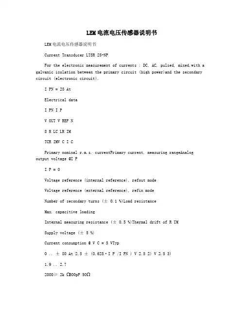
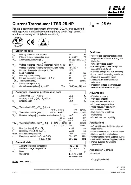
LEM电流电压传感器说明书LEM电流电压传感器说明书Current Transducer LTSR 25-NPFor the electronic measurement of currents : DC, AC, pulsed, mixed,with a galvanic isolation between the primary circuit (high power)and the secondary circuit (electronic circuit).I PN = 25 AtElectrical dataI PN I PV OUT V REF NS R LC LR IMTCR IMV C I CPrimary nominal r.m.s. currentPrimary current, measuring rangeAnalog output voltage @I PI P = 0Voltage reference (internal reference), refout modeVoltage reference (external reference), refin modeNumber of secondary turns (± 0.1 %)Load resistanceMax. capacitive loadingInternal measuring resistance (± 0.5 %)Thermal drift of R IMSupply voltage (± 5 %)Current consumption @ V C = 5 VTyp0 .. ± 80 At 2.5 ± (0.625·I P /I PN ) V 2.5 2) V 2.5 3)1.9 ..2.72000≥ 2k Ω500pF 50ΩFeatures•Closed loop (compensated) multi-•••••••range current transducer using theHall effectUnipolar voltage supplyInsulated plastic case recognizedaccording to UL 94-V0Compact design for PCB mountingIncorporated measuring resistanceExtended measuring rangeAccess to the internal voltagereferencePossibility to feed the transducerreference from external supply.Accuracy - Dynamic performance dataAdvantages± 0.2± 0.7Accuracy @ I PN , T A = 25°CAccuracy with R IM @ I PN , T A = 25°CLinearity errorTCV OUT Thermal drift of V OUT / VREF @ IP = 0TC εG V OM- 40°C .. + 85°C37.5 ppm/KThermal drift of the gain- 40°C .. + 85°C50 6) ppm/KResidual voltage @ IP = 0, a fter an overload of3 x I PN ± 0.5mV5 x I PN ± 2.0mV 10 x I PN ± 2.0mVThermal drift of internal VREF @ IP = 0 - 10°C .. + 85°C 50ppm/K- 40°C .. - 10°C 100ppm/KReaction time @ 10 % of I PN 60A/µsFrequency bandwidth(0 .. - 0.5 dB)DC .. 100kHz(- 0.5 .. 1 dB)DC .. 200kHz Ambient operating temperatureAmbient storage temperatureMassStandards- 40 .. + 85- 40 .. + 10010EN 50178 : 1997I EC 60950-1 : 2001•••••••Excellent accuracyVery good linearityVery low temperature driftOptimized response timeWide frequency bandwidthNo insertion lossesHigh immunity to externalinterference•Current overload capability.TCV REF t ra t rApplications•AC variable speed drives and servo•••••motor drivesStatic converters for DC motor drivesBattery supplied applicationsUninterruptible Power Supplies (UPS)Switched Mode Power Supplies (SMPS)Power supplies for weldingapplications.General dataT A T S mApplication Domain•Industrial.Copyright protected.see overleaf.051123/6LEM reserves the right to carry out modifications on its transducers, in order to improve them, without previous notice.Page 1/3Current Transducer LTSR 25-NPIsolation characteristics。
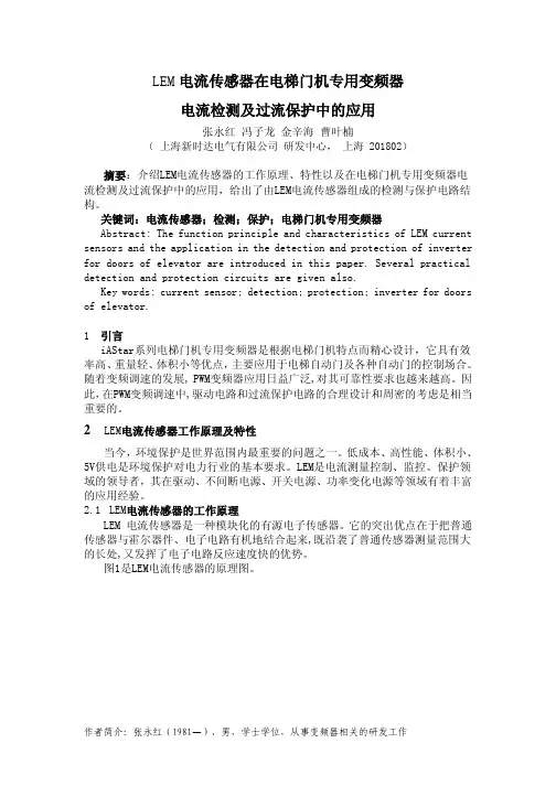
LEM电流传感器在电梯门机专用变频器电流检测及过流保护中的应用张永红冯子龙金辛海曹叶楠(上海新时达电气有限公司研发中心,上海201802)摘要:介绍LEM电流传感器的工作原理、特性以及在电梯门机专用变频器电流检测及过流保护中的应用,给出了由LEM电流传感器组成的检测与保护电路结构。
关键词:电流传感器;检测;保护;电梯门机专用变频器Abstract: The function principle and characteristics of LEM current sensors and the application in the detection and protection of inverter for doors of elevator are introduced in this paper. Several practical detection and protection circuits are given also.Key words: current sensor; detection; protection; inverter for doors of elevator.1引言iAStar系列电梯门机专用变频器是根据电梯门机特点而精心设计,它具有效率高、重量轻、体积小等优点,主要应用于电梯自动门及各种自动门的控制场合。
随着变频调速的发展, PWM变频器应用日益广泛,对其可靠性要求也越来越高。
因此,在PWM变频调速中,驱动电路和过流保护电路的合理设计和周密的考虑是相当重要的。
2LEM电流传感器工作原理及特性当今,环境保护是世界范围内最重要的问题之一。
低成本、高性能、体积小、5V供电是环境保护对电力行业的基本要求。
LEM是电流测量控制、监控、保护领域的领导者,其在驱动、不间断电源、开关电源、功率变化电源等领域有着丰富的应用经验。
2.1 LEM电流传感器的工作原理LEM 电流传感器是一种模块化的有源电子传感器。
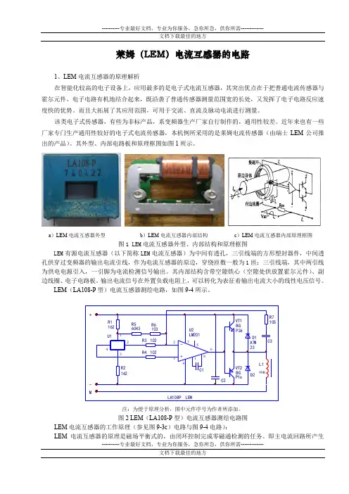
----------专业最好文档,专业为你服务,急你所急,供你所需-------------莱姆(LEM )电流互感器的电路1、LEM 电流互感器的原理解析在智能化较高的电子设备上,应用最多的是电子式电流互感器,其突出优点在于把普通电流传感器与霍尔元件、电子电路有机地结合起来,既沿袭了普通传感器测量范围宽的长处,又发挥了电子电路反应速度快的优势。
而且大拓展了其应用范围,可用于交流、直流及脉动电流进行测量。
该类电子式传感器,有些为非标产品,系变频器生产厂家自行制作的,通用性较差。
近年来也有一些厂家专门生产通用性较好的电子式电流传感器,本机例所采用的是莱姆电流传感器(由瑞士LEM 公司推出的产品)。
其外型、内部电路板和原理框图如图1所示。
a )LEM 电流互感器外型b )LEM 电流互感器内部结构c )LEM 电流互感器内部原理框图图1 LEM 电流互感器外型、内部结构和原理框图LEM 有源电流互感器(以下简称LEM 电流互感器)为中间有透孔,三引线端的方形塑封器件,中间透孔供穿过变频器的输出电流引线,作为电流互感器的原边,穿绕匝数一般为1匝;三引线端,其中两引线为供电电源引入,一引脚为电流检测信号输出。
其内部结构含带空隙铁心(空隙处供放置霍尔元件)、副边线圈、电子电路板。
输出电流信号在外置负载电阻上,可以转化为表征着输出电流大小的线性电压信号。
LEM (LA108-P 型)电流互感器测绘电路,如图9-4所示。
注:为便于原理分析,图中元件序号为作者所添加。
图2 LEM (LA108-P 型)电流互感器测绘电路图LEM 电流互感器的工作原理(参见图9-3c )电路与图9-4电路):LEM 电流互感器的原理是磁场平衡式的,由闭环控制完成零磁通检测的任务。
即主电流回路所产生的磁场,通过一个次线线圈L1(1000匝,直流电阻99Ω)的电流所产生的磁场进行了补偿,使霍尔器件U1始终处于检测零磁通的工作状态。
当主回路有一大电流Ip流过时,在导体周围产生相应的电磁场Hp,穿过磁场的磁力线被聚集环聚集,并作用于霍尔器件,霍尔器件U1产生电流信号输出;此电流信号经信号放大器U2(差分放大器)放大,输入至功率放大电路(由VT1、VT2构成的互补放大器),从而产生一个流经L1的补偿电流Is。
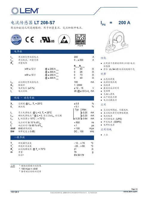
Page 1/3电流传感器 LT 208-S7原边和副边之间是绝缘的,用于测量直流、交流和脉冲电流。
电参数I PN原边额定有效值电流 200AI PM 原边电流, 测量范围 0 .. ± 300AR M 测量电阻R M min R M max with ± 12 V @ ± 200 A max 0 50 Ω@ ± 300 A max 0 26 Ω with ± 15 V @ ± 200 A max 0 73 Ω @ ± 300 A max0 40ΩI SN 副边额定有效值电流 100 mA K N 转换率1 : 2000V C 电源电压 (± 5 %) ± 12 .. 15 V I C电流消耗28 (@ ± 12V) + I S mA精度 - 动态参数X G总精度 @ I PN , T A = 25°C ± 0.5 %εL线性度 < 0.1 %Typ Max I O 零点失调电压 @ I P = 0, T A = 25°C± 0.20 mA I OM 磁性失调电流 1) @ I P = 0, 通过 3 x I PN 的过载 ± 0.20 mA I OT I O 的温漂 (- 10°C .. + 70°C) ± 0.20 ± 0.64 mA t ra 反应时间 to 10 % of I PN < 500 ns t r 响应时间 2) to 90 % of I PN < 1 µs di/dt di/dt 跟随精度 > 100 A/µs BW频带宽度 (- 3 dB)DC .. 100kHz一般参数T A环境操作温度 - 10 .. + 70 °C T S 环境贮存温度- 25 .. + 80 °C R S 副边线圈电阻 @ T A = 70°C 21 Ωm 质量 79g标准3)EN 50178注释1)磁场的强磁力的结果 2)100 A/µs 的 di/dt3)备有相应的检测清单I PN = 200 A 性能应用霍尔原理的闭环(补偿)电流 ●传感器符合 ●UL 94-V0 标准的绝缘外壳优势出色的精度 ●良好的线性度 ●低温漂 ●最佳的反应时间 ●宽频带 ●无插入损失 ●抗干扰能力强 ●电流过载能力●应用交流变频调速、伺服电机 ●直流电机牵引的静电转换 ●电池电源 ●不间断电源 ●(UPS)开关电源 ●(SMPS)电焊机电源 ●应用领域工业●用霍尔原理的闭环(补偿)电流传感器•符合 UL 94-V0标准的绝缘外壳优势•出色的精度•良好的线性度•低温漂•最佳的反应时间•宽频带•无插入损失•抗干扰能力强•电流过载能力应用•交流变频调速伺服电机•直流电机牵引的静电转换•电池电源•不间断电源 (UPS)•开关电源 (SMPS)•电焊机电源I PN =50 APage 2/3电流传感器 LT 208-S7电隔离性能V d 交流隔离耐压测试有效值 1) , 50 Hz, 1 分钟 3.52kV V w 瞬态耐压 1.2/50 µs 6.5 kVMin dCp 爬电距离 2)10 mm dCI 电气间隙距离 2) 6mmCTI比较路经指数 (group IIIa)275应用参考依据 EN 50178 及 IEC 61010-1 标准,应用条件示范如下:负载电压类别: ●OV 3污染等级: ●PD2非特殊应用领域●注释 1)原副边之间2)原边至外壳表面端子安全事项传感器必须按照使用说明要求安放在符合应用标准和安全要求的电子或电气设备中.注意,小心电击传感器工作时,某些部位可能会承受危险电压(如原边母排,电源)忽视这些将导致损坏和严重危险. 传感器是内置式设备,在安装完毕后其导电部分一定要保证不被外界触及. 可采用保护壳或附加屏蔽铠装. 主电源必须能被断开.EN 50178IEC 61010-1dCp, dCI,额定耐压值额定电压单绝缘600 V 600 V 加强型绝缘300 V300 VV wPage 3/3说明I ●S 在 I P 按箭头方向流动时, 是正向的.原边导体温度不超过 ●100°C.母排完全充满原边穿孔时动态表现 ● (di/dt 和响应时间)为最佳.此模块为标准传感器. 对于不同的应用 ● (电源电压、匝比, 单项测量...)请与我们联系.机械性能自然公差 ● ± 0.5 mm紧固点 ● 2 孔 ∅ 5.4 mm 原边穿孔 ● ∅ 20 mm副边连接 ● 插座 2541 WV-4P(上海嘉仁)LT 208-S7外形尺寸 (in mm)。
LEM Page 1/3LEM reserves the right to carry out modifications on its transducers, in order to improve them, without previous notice.051123/6Current Transducer LTSR 25-NPFor the electronic measurement of currents : DC, AC, pulsed, mixed,with a galvanic isolation between the primary circuit (high powerand the secondary circuit (electronic circuit.Electrical dataI PN Primary nominal r.m.s. current25AtI PPrimary current, measuring range0 .. ± 80 1At V OUT Analog output voltage @I P2.5 ± (0.625·I P /I PN V I P = 02.5 2 V V REF Voltage reference (internal reference, refout mode2.5 3VVoltage reference (external reference, refin mode1.9 ..2.74V NS Number of secondary turns (± 0.1 %2000R LLoad resistance ≥ 2k ΩC LMax. capacitive loading500pF R IMInternal measuring resistance (± 0.5 %50ΩTCR IMThermal drift of R IM< 50ppm/KV C Supply voltage (± 5 %5V I CCurrent consumption @ V C = 5 VTyp28 + I S 5 + (V OUT /R L mAAccuracy - Dynamic performance dataXAccuracy @ I PN , T A = 25°C± 0.2%Accuracy with R IM @ I PN , T A = 25°C± 0.7%εLLinearity error< 0.1%MaxTCV OUT Thermal drift of V OUT / VREF @ IP = 0- 40°C .. + 85°C37.5 ppm/K TC εG Thermal drift of the gain- 40°C .. + 85°C50 6 ppm/KV OMResidual voltage @ IP = 0, a fter an overload of3 x I PN ± 0.5mV5 x I PN ± 2.0mV 10 x I PN ± 2.0mVTCV REF Thermal drift of internal VREF @ IP = 0 - 10°C .. + 85°C 50ppm/K - 40°C .. - 10°C 100ppm/Kt ra Reaction time @ 10 % of I PN < 100ns t rResponse time @ 90 % of IPN < 400ns di/dtdi/dt accurately followed> 60A/µsf Frequency bandwidth(0 .. - 0.5 dBDC .. 100kHz(- 0.5 .. 1 dBDC .. 200kHz General dataT A Ambient operating temperature- 40 .. + 85°CT S Ambient storage temperature- 40 .. + 100°CmMass10gStandardsEN 50178 : 1997I EC 60950-1 : 2001see overleaf.Features•Closed loop (compensated multi-range current transducer using theHall effect •Unipolar voltage supply•Insulated plastic case recognizedaccording to UL 94-V0•Compact design for PCB mounting•Incorporated measuring resistance•Extended measuring range•Access to the internal voltagereference•Possibility to feed the transducerreference from external supply.Advantages•Excellent accuracy•Very good linearity•Very low temperature drift•Optimized response time•Wid e frequency bandwidth•No insertion losses•High immunity to externalinterference•Current overload capability.Applications•AC variable speed drives and servomotor drives•Static converters for DC motor drives•Battery supplied applications•Uninterruptible Power Supplies (UPS•Switched Mode Power Supplies (SMPS•Power supplies for weldingapplications.I PN = 25 AtCopyright protected.Application Domain•Industrial.LEM Page 2/3LEM reserves the right to carry out modifications on its transducers, in order to improve them, without previous notice.051123/6Current Transducer LTSR 25-NPIsolation characteristicsV d R.m.s. voltage for AC isolation test, 50/60 Hz, 1 mn3kV w Impulse withstand voltage 1.2/50 µs> 8kV Min V e R.m.s. voltage for partial discharge extinction @ 10pC> 1.5kV Min dCp Creepage distance 7 15.35m m dCl Clearance distance 86.2m mCTIComparative Tracking Index (Group III a175Application examplesAccording to EN 50178 and IEC 61010-1 standards and following conditions :•Over voltage category OV 3•Pollution degree PD2SafetyThis transducer must be used in electric/electronic equipment with respect to applicablestandards and safety requirements in accordance with the following manufacturer's operatinginstructions.Caution, risk of electrical shockWhen operating the transducer, certain parts of the module can carry hazardous voltage (eg.primary busbar, power supply.Ignoring this warning can lead to injury and/or cause serious damage.This transducer is a built-in device, whose conducting parts must be inaccessible afterinstallation.A protective housing or additional shield could be used.Main supply must be able to be disconnected.Notes1Only in refout mode or with external REF less than 2.525 Vand greater than 2.475 V. For external REF out of theselimits see leaflet.2V OUT is linked to V REF , by conception the differencebetween these two nodes for I P = 0 is maximum ± 25 mV,2.475 V < V OUT <2.525 V.3In Refout mode at T A = 25°C, 2.475 V< V REF < 2.525 V.The minim al impedance loading the ref pin should be> 220 kΩ.Internal impedance = 600 Ω. For most applications you needto buffer this output to feed it into an ADC for example.4To overdrive the REF (1.9 V .. 2.7 V max. ± 1 mA is needed.5Please see the operation principle on the other side.6Only due to TCR IM. 7 On housing.8On PCB with soldering pattern UTEC93-703.LEM Page 3/3LEM reserves the right to carry out modifications on its transducers, in order to improve them, without previous notice.051123/6Dimensions LTSR 25-NP (in mm. 1 mm = 0.0394 inchMechanical characteristics•General tolerance± 0.2 mm•Fastening & connection of primary6 pins 0.8 x 0.8 mmRecommended PCB hole1.3 mm•Fastening & connection of secondary4 pins 0.5 x 0.35 mmRecommended PCB hole0.8 mm•Additional primary through-hole∅ 3.2 mmRemarks•V OUT is positive when I P flows from terminals 1, 2, 3 to terminals6, 5, 4•For the EMC, the acceptance criteria are available on request.•Temperature of the primary jumper should not exceed 100 [°C].- I Pmax - I PN 0 I PN I PmaxP [ At ]V [ V ]Output Voltage - Primary Current9 Output voltage when LTSR 25-NP is used with internal reference.。

LEM电流传感器在电梯门机专用变频器电流检测及过流保护中的应用张永红冯子龙金辛海曹叶楠(上海新时达电气有限公司研发中心,上海201802)摘要:介绍LEM电流传感器的工作原理、特性以及在电梯门机专用变频器电流检测及过流保护中的应用,给出了由LEM电流传感器组成的检测与保护电路结构。
关键词:电流传感器;检测;保护;电梯门机专用变频器Abstract: The function principle and characteristics of LEM current sensors and the application in the detection and protection of inverter for doors of elevator are introduced in this paper. Several practical detection and protection circuits are given also.Key words: current sensor; detection; protection; inverter for doors of elevator.1引言iAStar系列电梯门机专用变频器是根据电梯门机特点而精心设计,它具有效率高、重量轻、体积小等优点,主要应用于电梯自动门及各种自动门的控制场合。
随着变频调速的发展, PWM变频器应用日益广泛,对其可靠性要求也越来越高。
因此,在PWM变频调速中,驱动电路和过流保护电路的合理设计和周密的考虑是相当重要的。
2LEM电流传感器工作原理及特性当今,环境保护是世界范围内最重要的问题之一。
低成本、高性能、体积小、5V供电是环境保护对电力行业的基本要求。
LEM是电流测量控制、监控、保护领域的领导者,其在驱动、不间断电源、开关电源、功率变化电源等领域有着丰富的应用经验。
2.1 LEM电流传感器的工作原理LEM 电流传感器是一种模块化的有源电子传感器。
lem电流传感器原理LEM电流传感器原理引言:LEM电流传感器是一种常用的电流测量设备,它能够将电流转化为电压信号输出,并广泛应用于工业控制、电力系统、电子设备等领域。
本文将详细介绍LEM电流传感器的原理及其工作机制。
一、LEM电流传感器的基本原理LEM电流传感器采用了霍尔效应原理,通过在导体上加上外加磁场,使得电流产生磁场,进而通过霍尔效应感应出电流的大小。
具体原理如下:1.1 霍尔效应霍尔效应是指当电流通过导体时,垂直于电流方向的磁场作用下,导体的一侧会产生电势差。
这种现象是由于磁场作用下的洛伦兹力使电子偏转而产生的。
1.2 磁场感应当电流通过导体时,根据右手定则,电流产生的磁场方向垂直于电流方向。
而磁场的大小和电流成正比。
1.3 霍尔元件为了感应电流产生的磁场,LEM电流传感器中使用了霍尔元件。
霍尔元件是一种基于霍尔效应的磁敏元件,能够将磁场转化为电压信号输出。
二、LEM电流传感器的工作机制基于以上原理,LEM电流传感器的工作流程如下:2.1 封装和连接LEM电流传感器通常采用封装的形式,方便安装和连接。
它通常由传感器主体、输入输出端子和电源端子组成。
2.2 磁场感应当待测电流通过传感器主体时,会产生磁场。
传感器主体中的霍尔元件感应到这个磁场,并将其转化为电压信号。
2.3 信号处理通过对电压信号的处理,可以得到与电流大小成正比的输出信号。
通常,该信号经过放大、滤波等处理,以提高测量精度和减小噪声干扰。
2.4 输出结果经过信号处理后,LEM电流传感器将输出一个与待测电流大小成正比的电压信号。
用户可以通过测量该电压信号来得到电流的准确值。
三、LEM电流传感器的优势和应用LEM电流传感器具有以下优势:3.1 非接触式测量LEM电流传感器采用非接触式测量,不需要与被测电流直接接触,避免了测量过程中的安全隐患。
3.2 宽量程LEM电流传感器具有宽范围的量程选择,可以满足不同应用场景的需求。
3.3 高准确度LEM电流传感器采用高精度的霍尔元件和信号处理技术,具有较高的测量精度和稳定性。
LEM Page 1/3LEM reserves the right to carry out modifications on its transducers, in order to improve them, without previous notice.051123/6Current Transducer LTSR 25-NPFor the electronic measurement of currents : DC, AC, pulsed, mixed,with a galvanic isolation between the primary circuit (high power)and the secondary circuit (electronic circuit).Electrical dataI PN Primary nominal r.m.s. current 25AtI PPrimary current, measuring range 0 .. ± 80 1)At V OUT Analog output voltage @I P2.5 ± (0.625·I P /I PN )V I P = 02.5 2)V V REF Voltage reference (internal reference), refout mode2.5 3)VVoltage reference (external reference), refin mode1.9 ..2.74)V NS Number of secondary turns (± 0.1 %)2000R L Load resistance≥ 2k ΩC L Max. capacitive loading500pF R IMInternal measuring resistance (± 0.5 %)50ΩTCR IM Thermal drift of R IM< 50ppm/K V C Supply voltage (± 5 %)5V I CCurrent consumption @ V C = 5 V Typ28 + I S 5)+ (V OUT /R L )mAAccuracy - Dynamic performance dataXAccuracy @ I PN , T A = 25°C± 0.2%Accuracy with R IM @ I PN , T A = 25°C ± 0.7%εLLinearity error< 0.1%MaxTCV OUT Thermal drift of V OUT / V REF @ I P = 0- 40°C .. + 85°C 37.5 ppm/KTC εG Thermal drift of the gain - 40°C .. + 85°C 50 6)ppm/K V OMResidual voltage @ I P = 0, a fter an overload of 3 x I PN ± 0.5mV5 x I PN ± 2.0mV 10 x I PN ± 2.0mVTCV REF Thermal drift of internal V REF @ I P = 0 - 10°C .. + 85°C 50ppm/K- 40°C .. - 10°C 100ppm/Kt ra Reaction time @ 10 % of I PN < 100ns t rResponse time @ 90 % of I PN < 400ns di/dt di/dt accurately followed > 60A/µs fFrequency bandwidth (0 .. - 0.5 dB)DC .. 100kHz(- 0.5 .. 1 dB)DC .. 200kHz General dataT A Ambient operating temperature- 40 .. + 85°C T S Ambient storage temperature - 40 .. + 100°C mMass10gStandardsEN 50178 : 1997I EC 60950-1 : 2001Notes :see overleaf.Features•Closed loop (compensated) multi-range current transducer using the Hall effect•Unipolar voltage supply•Insulated plastic case recognized according to UL 94-V0•Compact design for PCB mounting •Incorporated measuring resistance •Extended measuring range •Access to the internal voltage reference•Possibility to feed the transducer reference from external supply.Advantages•Excellent accuracy •Very good linearity•Very low temperature drift •Optimized response time •Wide frequency bandwidth •No insertion losses•High immunity to external interference•Current overload capability.Applications•AC variable speed drives and servo motor drives•Static converters for DC motor drives •Battery supplied applications•Uninterruptible Power Supplies (UPS)•Switched Mode Power Supplies (SMPS)•Power supplies for welding applications.I PN = 25 AtCopyright protected.Application Domain•Industrial.LEM Page 2/3LEM reserves the right to carry out modifications on its transducers, in order to improve them, without previous notice.051123/6Current Transducer LTSR 25-NPIsolation characteristicsV d R.m.s. voltage for AC isolation test, 50/60 Hz, 1 mn 3kV V w Impulse withstand voltage 1.2/50 µs> 8kV Min V e R.m.s. voltage for partial discharge extinction @ 10pC > 1.5kV Min dCp Creepage distance 7)15.35m m dCl Clearance distance 8)6.2m mCTIComparative Tracking Index (Group III a)175Application examplesAccording to EN 50178 and IEC 61010-1 standards and following conditions :•Over voltage category OV 3•Pollution degree PD2SafetyThis transducer must be used in electric/electronic equipment with respect to applicable standards and safety requirements in accordance with the following manufacturer's operating instructions.Caution, risk of electrical shockWhen operating the transducer, certain parts of the module can carry hazardous voltage (eg.primary busbar, power supply).Ignoring this warning can lead to injury and/or cause serious damage.This transducer is a built-in device, whose conducting parts must be inaccessible after installation.A protective housing or additional shield could be used.Main supply must be able to be disconnected.Notes1)Only in refout mode or with external REF less than 2.525 V and greater than 2.475 V. For external REF out of these limits see leaflet.2)V OUT is linked to V REF , by conception the differencebetween these two nodes for I P = 0 is maximum ± 25 mV,2.475 V < V OUT < 2.525 V.3)In Refout mode at T A = 25°C, 2.475 V< V REF < 2.525 V.The minimal impedance loading the ref pin should be > 220 k Ω.Internal impedance = 600 Ω. For most applications you need to buffer this output to feed it into an ADC for example.4)To overdrive the REF (1.9 V .. 2.7 V) max. ± 1 mA is needed.5)Please see the operation principle on the other side.6)Only due to TCR IM . 7)On housing.8)On PCB with soldering pattern UTEC93-703.LEM Page 3/3LEM reserves the right to carry out modifications on its transducers, in order to improve them, without previous notice.051123/6Dimensions LTSR 25-NP (in mm. 1 mm = 0.0394 inch)Mechanical characteristics•General tolerance± 0.2 mm•Fastening & connection of primary 6 pins 0.8 x 0.8 mm Recommended PCB hole1.3 mm•Fastening & connection of secondary 4 pins 0.5 x 0.35 mm Recommended PCB hole0.8 mm •Additional primary through-hole∅ 3.2 mmRemarks•V OUT is positive when I P flows from terminals 1, 2, 3 to terminals 6, 5, 4•For the EMC, the acceptance criteria are available on request.•Temperature of the primary jumper should not exceed 100 [°C].- I Pmax - I PN 0 I PN I PmaxP [ At ]V [ V ]Output Voltage - Primary CurrentNote : 9) Output voltage when LTSR 25-NP is used with internalreference.。
lem电流传感器原理LEM电流传感器原理引言:LEM电流传感器是一种常用的电流测量设备,广泛应用于电力系统、工业自动化和电子设备中。
本文将详细介绍LEM电流传感器的原理和工作方式。
一、电流传感器的基本原理电流传感器是一种用于测量电流的装置,它通过感应电流产生的磁场来测量电流的大小。
LEM电流传感器采用了霍尔效应,基于洛伦兹力的原理来实现电流的测量。
二、霍尔效应的原理霍尔效应是指当电流通过导体时,在导体两侧产生一种电场,这种电场会使导体中的电子受到一种力的作用,从而引起导体的电压差。
利用这种效应,可以实现电流的测量。
三、LEM电流传感器的结构LEM电流传感器通常由铁芯、感应线圈和霍尔元件组成。
铁芯用于增强电流产生的磁场,感应线圈将电流转化为磁场,并通过霍尔元件测量磁场的强度。
四、LEM电流传感器的工作原理当电流通过感应线圈时,感应线圈产生的磁场会使铁芯饱和。
饱和后的铁芯会形成一个稳定的磁场,该磁场与电流成正比。
霍尔元件安装在铁芯上,可以感应到磁场的强度。
通过测量霍尔元件输出的电压,就可以得到电流的大小。
五、LEM电流传感器的特点1. 非接触式测量:LEM电流传感器与被测电路之间没有电气连接,可以避免安全隐患。
2. 高精度:LEM电流传感器具有较高的测量精度,可以满足工业自动化和电力系统的要求。
3. 宽测量范围:LEM电流传感器的测量范围通常较宽,可以满足不同应用场景的需求。
4. 快速响应:LEM电流传感器的响应速度较快,可以实时监测电流的变化。
六、LEM电流传感器的应用1. 电力系统:LEM电流传感器广泛应用于电力系统中的电流测量和保护装置中,例如电能计量、断路器和接触器。
2. 工业自动化:LEM电流传感器用于工业自动化中的电机控制、变频器和电力负载监测等领域。
3. 电子设备:LEM电流传感器也用于电子设备中的电流测量和控制,例如电源管理、电池充放电控制等。
结语:LEM电流传感器是一种重要的电流测量装置,基于霍尔效应实现了电流的非接触式测量。
Page 1/3I PN = 75 .. 400 A特性基于霍尔原理测量●●原边和副边电路采用电隔离●●隔离电压●●●3000 V低功耗●●测量范围宽●●●(3 x I PN )符合●●●UL 94-V0 标准的绝缘外壳优点便于贴装●●体积小●●适用于宽电流变化范围测量●●抗外界干扰能力强●●应用交流变速驱动●●直流电机牵引的静电转换●●电池电源●●不间断电源●●(UPS)开关电源●●(SMPS)电焊机电源●●应用领域工业●●电流传感器●HAS 75 .. 400-S/SP54原边与副边之间是绝缘的,用于测量直流、交流和脉冲电流...电参数型号 原边额定电流有效值 原边电流测量范围I PN (A)I PM (A) HAS 75-S/SP54 75 ± 225 HAS 100-S/SP54 100 ± 300 HAS 150-S/SP54 150 ± 450 HAS 200-S/SP54 200 ± 600 HAS 300-S/SP54 300 ± 900 HAS 400-S/SP54 400± 900V C 电源电压 (± 5 %) 1)± 15 V I C 电流消耗 ± 15 mA R IS 绝缘电阻●@ 500 VDC> 1000 M ΩV OUT 输出电压(模拟值)@ ± I PN , R L =10 k Ω, T A = 25°C ± 4V ± 40 mV R OUT 输出内阻 约●100 ΩR L负载电阻> 10 k Ω精度●-●动态参数X精度●@●I PN , T A = 25°C (excluding offset) < ± 1 %εL 线性误差 2) (0 .. ± I PN ) < ± 1 % of I PN V OE 电失调电压,T A = 25°C < ± 20 mV V OH 1倍●I PN 偏移后,当●I P = 0 时的滞回失调电压●< ± 20 mV TCV OE 电失调电压温度系数 < ± 1 mV/K TCV OUT 输出电压温度系数(% of reading) < ± 0.1 %/K t r 响应时间(以I PN 的90 % 为准) < 3 µs di/dt di/dt 跟随精度 > 50 A/µs BW 频带宽度●(- 3 dB) 3)DC .. 50 kHzT A环境操作温度● - 10 .. + 80 °C 一般参数T S 环境储存温度● - 25 .. + 80 °C m 质量 约60 g标准 4)EN 50178: 1997注释:●1)●●在●± 12 V ≤ V C < ± 15 V , 会相应缩小测量范围●●2)●●所示参数为线性数据,不包括电性偏移量●●3)为避免在高频下内核过热,请按照相关技术文件降低额定值●●4)●欲获取技术详细信息,请参照相关特性报告V间是绝缘的,主要用于测量直流、交流、和脉冲电流...,I PN =50 .. 300 AV OUT =± 4 V特性·基于霍尔原理测量·原边和副边电路采用电隔离·隔离电压 3000 V ~·低功耗·测量范围宽 (3 x I )·符合UL94-V0标准的绝缘外壳优点·便于贴装·体积小·适用于宽电流变化范围测量·抗外界干扰能力强.应用·交流变速驱动·直流电机牵引的静电转换·电池电源·不间断电源(UPS)·开关电源(SMPS)·电焊机电源北京莱姆电子有限公司B 1北京空港工业区区标准厂房#:+86(10)80483178电话B 1空港工业区区标准厂房#: 网址传真: + 86 (10) 80484303101300北京,中国,邮编:E-mail: BJL@BJ-LEM注意:污染等级 2, 负载电压类别 III.所示参数为线性数据,不包括电性偏移量为避免在高频下内核过热,请参照按照相关技术文件降低额定值欲获取技术详细信息,请参照相关特性报告在± 12V ≤ Vc<± 15V,会相应缩小测量范围Page 2/3电流传感器●HAS 75 .. 400-S/SP54电隔离性能V d 交流隔离耐压测试有效值●, 50 赫兹, 1 分钟 3.6kV V w 瞬态耐压1.2千伏/50 微秒 > 6.6 kV Min dCp 爬电距离 7.08 mm dCI 电气间隙距离 6.23mmCTI比较路经指数(group IIIa)275应用参考根据 EN 50178 和 IEC 61010-1●标准,应用条件示范如下:负载电压类别●● OV 3污染等级●●●PD2非特殊应用领域●●安全事项传感器必须按照使用说明要求安放在符合应用标准和安全要求的电子或电气设备中。
lem电流传感器原理LEM电流传感器原理引言:电流传感器是一种用于测量电流的装置,它能够将电流信号转换为与之成正比的电压信号或电流信号。
而LEM电流传感器则是一种采用霍尔效应的非接触式电流传感器,其原理简单而高效。
一、LEM电流传感器的基本原理LEM电流传感器采用了霍尔效应原理,通过测量磁感应强度的变化来间接测量电流。
它由一个铁芯和绕在铁芯上的线圈组成。
当电流通过线圈时,会产生磁场,进而使铁芯磁化。
当铁芯磁化时,铁芯上的霍尔元件会感应到磁场的变化,并产生相应的电压信号。
通过测量这个电压信号的变化,我们可以推算出通过线圈的电流大小。
二、LEM电流传感器的工作原理LEM电流传感器可以分为闭环式和开环式两种。
闭环式电流传感器是指将被测电流通过主回路和次回路连接在一起,形成一个闭合的回路。
主回路中的电流通过线圈产生磁场,而次回路中的霍尔元件感应到这个磁场并产生相应的电压信号。
这个电压信号经过放大和处理后,就可以获得准确的电流值。
而开环式电流传感器则是指将被测电流通过线圈产生磁场,而霍尔元件直接感应到这个磁场并产生电压信号。
这个电压信号经过放大和处理后,也可以获得准确的电流值。
开环式电流传感器相对于闭环式电流传感器更加简单和便捷,但在一些特殊场合可能不太适用。
三、LEM电流传感器的优势LEM电流传感器具有以下几个优势:1. 非接触式测量:LEM电流传感器不需要与被测电流直接接触,减少了电路的复杂性和安全风险。
2. 高精度:LEM电流传感器采用了先进的霍尔效应原理,具有高精度和稳定性。
3. 宽频率范围:LEM电流传感器可适用于不同频率范围的电流测量,具有很高的通用性。
4. 快速响应:LEM电流传感器的响应速度非常快,可以实时监测电流的变化。
5. 低功耗:LEM电流传感器的功耗较低,适用于长时间运行的应用场景。
结论:通过对LEM电流传感器的原理和工作原理的介绍,我们可以看到它作为一种非接触式电流传感器具有很多优势。
lem电流传感器原理LEM电流传感器原理引言:在现代工业和电力系统中,电流的准确测量对于设备的安全运行至关重要。
LEM电流传感器是一种常用的传感器,它通过非接触式的方式测量电流,并将其转换为可量化的电信号。
本文将介绍LEM电流传感器的原理及其工作机制。
一、LEM电流传感器的基本原理LEM电流传感器是基于霍尔效应的原理工作的。
霍尔效应是指当有电流通过导体时,垂直于电流方向的方向上会产生一种横向电场。
利用霍尔效应,LEM电流传感器可以测量通过导线的电流强度。
二、LEM电流传感器的工作机制LEM电流传感器由两个主要部分组成:霍尔传感器和磁芯。
其中,霍尔传感器是用来测量电流强度的核心部件,而磁芯则用来放置电流导线,以产生磁场。
当电流通过被测导线时,磁芯会产生相应的磁场。
这个磁场会通过霍尔传感器,进而激活霍尔元件。
霍尔元件会根据磁场的强度和方向,输出对应的电压信号。
通过测量霍尔元件输出的电压信号,就可以得到电流的准确数值。
三、LEM电流传感器的优点1. 非接触式测量:LEM电流传感器采用非接触式的测量方式,不需要直接接触电流导线,减少了测量过程中的安全风险。
2. 高精度测量:LEM电流传感器具有高精度的测量能力,可以实时监测和测量电流的变化。
3. 宽范围测量:LEM电流传感器适用于广泛的电流范围,可以满足不同应用场景的需求。
4. 快速响应:LEM电流传感器具有快速的响应速度,可以在瞬态条件下准确测量电流。
四、LEM电流传感器的应用领域1. 工业自动化:LEM电流传感器广泛应用于工业自动化系统中,用于监测和控制电机、驱动器和变频器等设备的电流。
2. 电力系统:LEM电流传感器用于电力系统的电流测量和保护,确保电网的安全运行。
3. 新能源领域:LEM电流传感器在太阳能和风能发电系统中,用于测量电流和监测系统的运行状态。
4. 汽车行业:LEM电流传感器被广泛应用于电动汽车和混合动力汽车中,用于测量电池和电机的电流。