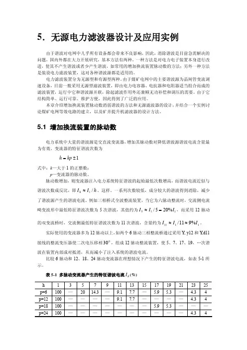
无源滤波器计算表
- 格式:xls
- 大小:254.50 KB
- 文档页数:5

基于Simulink的无源滤波器的设计摘要:为了防止电力输送时,传输电路产生的节点电压和线路电流波形产生的畸变,在进入某高校研究所后对电气设备造成较大的损害,通过Simulink软件对其进行无源滤波器的仿真设计,并对其参数进行计算。
通过对加入滤波器前后的不同的波形比较分析,显示谐波电流含有率、总谐波电流含有率等电能指标都得到了改善,确定了该设计的可行性。
关键词:无源滤波器;Simulink仿真;谐波;设计Passive filter design based on Simulink and parameters optimizationTIANHE COLLEGE OF GUANGDONG POLYTECHNIC NORMAL UNIVERSITY,School of Electrical and Electronic,GUANGDONG GUANGZHOU,510540Abstract:In order to avoid the distortion of node voltage and line current waveform produced by the transmission circuit,after entering a university institute,the electrical equipment is greatly damaged,the passive filter is simulated by Simulink software,and its parameters are calculated.Through the comparison and analysis of different waveforms before and after the filter is added,the energy indexes such as harmonic current and total harmonic current are improved,and the feasibility of the design is confirmed.Keyword:passive filter,Simulink,simulation,harmonic wave,design 引言随着现代非线性负载的大量使用,导致这些负载系统产生大量的谐波,传输线路的节点电压及线路电流的波形产生畸变,从而使得电能质量和设备使用寿命的降低并导致经济损失。
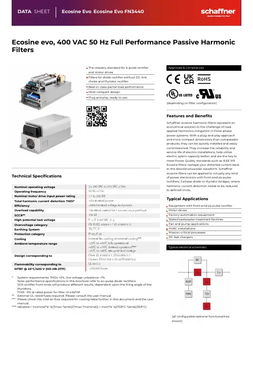
DATA SHEET Ecosine Evo Ecosine Evo FN3440Ecosine evo, 400 VAC 50 Hz Full Performance Passive Harmonic FiltersThe industry standard for 6-pulse rectifier and motor drivesFilters for diode rectifier without DC-link choke and thyristor rectifierBest-in-class partial load performance Most compact design Plug and play, ready to useTechnical SpecificationsNominal operating voltage 3 x 380 VAC to 415 VAC ±10%Operating frequency50 Hz ±1 Hz Nominal motor drive input power rating 1.1 to 250 kW Total harmonic current distortion THDi*≤5% at rated powerEfficiency>98% for rated voltage and powerOverload capability 1.6x rated current for 1 minute, once per hour SCCR**100 kAHigh potential test voltage P –> E 2160 VAC (1 s)Overvoltage category OV III (IEC 60664-1 / UL 61800-5-1)Earthing System TN, TT, IT Protection category IP 00, IP 20CoolingInternal fan cooling or external cooling***Ambient temperature range–25°C to +45°C fully operational+45°C to +70°C derated operation****–25°C to +85°C transport and storageDesign corresponding toFilter: UL 61800-5-1, EN 61800-5-1Chokes: EN 61558-2-20 or EN 60076-6Flammability corresponding to UL 94 V-2MTBF @ 45°C/400 V (Mil-HB-217F)>200,000 hoursSystem requirements: THDv <2%, line voltage unbalance <1%*Note: performance specifications in this brochure refer to six-pulse diode rectifiers.SCR rectifier front-ends will produce different results, dependent upon the firing angle of the thyristors.THDi ~5% at rated power for filter <6 kW/HPExternal UL-rated fuses required. Please consult the user manual.**Please check the inlet air flow required for cooling table further in this document and the usermanual.***Iderated = Inominal*√((Tmax-Tamb)/(Tmax-Tnominal)) = Inom*√((70°C-Tamb)/25°C)****Approvals & Compliances(depending on filter configuration)Features and BenefitsTypical ApplicationsSchaffner ecosine harmonic filters represent an economical solution to the challenge of load-applied harmonics mitigation in three-phase power systems. With a plug-and-play approach and more compact dimensions than comparable products, they can be quickly installed and easily commissioned. They increase the reliability and service life of electric installations, help utilize electric sytem capacity better, and are the key to meet Power Quality standards such as IEEE 519.Ecosine filters reshape your distorted current back to the desired sinusoidal waveform. Schaffner ecosine filters can be applied to virtually any kind of power electronics with front-end six-pulserectifiers, 3-phase diode or thyristor bridges, where harmonic current distortion needs to be reduced to defined limits.Equipment with front-end six-pulse rectifier Motor drivesFactory automation equipment Water/wastewater treatment facilities Fan and pump applications HVAC installations Mission-critical processes DC fast chargersTypical electrical schematic(all configurable optional functionalities shown)@ 400 V/50 Hz input current input current losses size[kW][Arms]***[Arms][kg][W]****FN 3440-1-110-E0_ _ _ _ _* 1.1 3.0 1.63761110A FN 3440-2-110-E0_ _ _ _ _* 2.2 5.5 3.261087110A FN 3440-4-112-E0_ _ _ _ _* 4.010 5.9313135112B FN 3440-6-112-E0_ _ _ _ _* 5.5138.1717183112C FN 3440-8-112-E0_ _ _ _ _*7.51611.121256112C FN 3440-11-113-E0_ _ _ _ _112416.328287113D FN 3440-15-113-E0_ _ _ _ _153222.232359113D FN 3440-19-113-E0_ _ _ _ _193828.233343113D FN 3440-22-115-E0_ _ _ _ _224532.548460115E FN 3440-30-115-E0_ _ _ _ _306044.449570115E FN 3440-37-115-E0_ _ _ _ _377554.860581115E FN 3440-45-115-E0_ _ _ _ _459066.767783115E FN 3440-55-115-E0_ _ _ _ _5511081.669858115E FN 3440-75-116-E0_ _ _ _ _751501111181036116G FN 3440-90-116-E0_ _ _ _ _901801341391166116G FN 3440-110-118-E0_ _ _ _ _1102101641581365118H FN 3440-132-118-E0_ _ _ _ _**1322601971761392118H FN 3440-160-118-E0_ _ _ _ _**1603202402021462118H FN 3440-200-118-E0_ _ _ _ _**2004003002101644118H FN 3440-250-119-E0XXSXX2505303763241746119J*Filter rating which does not require forced cooling or fan module**Filter rating which does not require RC damping module for rectifiers with EMI filter***Motor drive input current without harmonic filter****Typical losses @ 45°C, 400 V, 50 Hz and rated load powerFilter Power TerminalsTerminal designation*Screw thread Flex wire AWG Flex wire Screw torque value Max width**Frame sizecable lug[mm2][Nm][mm]110M314-220.4-2.50.57A 112M410-220.4-6 1.210B, C 113M66-180.75-16315D 115M81/0-810-50815E, F 116M83/0-810-95817G 118M103/0-500 kcmil95-2401035H 119M16350-750 kcmil185-4001048J*Recommended connector type: wire or cable lug for 110 to 113, only cable lug for 115 to 119** To fulfill creepage/clearance acc. UL 61800-5-1 without additional protection (insulation). Creepage/clearance can vary depending on applicable standard and must be reviewed by customer. Creepage/clearance may be reduced when additional protection (insulation) is provided.Filter Signal And Earth TerminalsTerminal type Screw thread Screw torque value Frame size[Nm]Signal M3*0.5All Earth (PE)M5 2.2A Earth (PE)M64B, C Earth (PE)M89D, E Earth (PE)M1017F, G, H Earth (PE)M1225J*Max width cable lug = 7 mm@ 400 V/50 Hz input current input current losses size[kW][Arms]***[Arms][kg][W]****FN 3440-1-110-E2_ _ _ _ _* 1.1 3.0 1.63861110A FN 3440-2-110-E2_ _ _ _ _* 2.2 5.5 3.261187110A FN 3440-4-112-E2_ _ _ _ _* 4.010 5.9315135112B FN 3440-6-112-E2_ _ _ _ _* 5.5138.1719183112C FN 3440-8-112-E2_ _ _ _ _*7.51611.123256112C FN 3440-11-113-E2_ _ _ _ _112416.332287113D FN 3440-15-113-E2_ _ _ _ _153222.236359113D FN 3440-19-113-E2_ _ _ _ _193828.237343113D FN 3440-22-115-E2_ _ _ _ _224532.553460115E FN 3440-30-115-E2_ _ _ _ _306044.455570115E FN 3440-37-115-E2_ _ _ _ _377554.866581115E FN 3440-45-115-E2_ _ _ _ _459066.773783115E FN 3440-55-115-E2_ _ _ _ _5511081.675858115E FN 3440-75-116-E2_ _ _ _ _751501111261036116G FN 3440-90-116-E2_ _ _ _ _901801341471166116G FN 3440-110-118-E2_ _ _ _ _1102101641751365118H FN 3440-132-118-E2_ _ _ _ _**1322601971941392118H FN 3440-160-118-E2_ _ _ _ _**1603202402191462118H FN 3440-200-118-E2_ _ _ _ _**2004003002271644118H FN 3440-250-119-E2FASXX2505303763501746119J*Filter rating which does not require forced cooling or fan module**Filter rating which does not require RC damping module for rectifiers with EMI filter***Motor drive input current without harmonic filter**** Typical losses @ 45°C, 400 V, 50 Hz and rated load powerFilter Power TerminalsTerminal designation*Screw thread Flex wire AWG Flex wire Screw torque value Max width**Frame sizecable lug[mm2][Nm][mm]110M314-220.4-2.50.57A 112M410-220.4-6 1.210B, C 113M66-180.75-16315D 115M81/0-810-50815E, F 116M83/0-810-95817G 118M103/0-500 kcmil95-2401035H 119M16350-750 kcmil185-4001048J*Recommended connector type: wire or cable lug for 110 to 113, only cable lug for 115 to 119** To fulfill creepage/clearance acc. UL 61800-5-1 without additional protection (insulation). Creepage/clearance can vary depending on applicable standard and must be reviewed by customer. Creepage/clearance may be reduced when additional protection (insulation) is provided.Filter Signal And Earth TerminalsTerminal type Screw thread Screw torque value Frame size[Nm]Signal M3*0.5All Earth (PE)M5 2.2A Earth (PE)M64B, C Earth (PE)M89D, E Earth (PE)M1017F, G, H Earth (PE)M1225J*Max width cable lug = 7 mm(Filters do not contain fan and do not contain aux. power supply )Table 1: Filter Configurations If External Air Flow Is Available For Cooling- For rectifiers without DC-link choke- For rectifiers without DC-link choke- Filters contain trap disconnectjumperE0XXJXX- For rectifiers without DC-link choke and with EMI filter - Filters contain RC damper moduleE0XXXRX- For rectifiers without DC-link choke and with EMI filter - Contain RC damper moduleand trap disconnect jumperE0XXJRX2022(Filters contain fan and aux. power supply )Table 2: Filter Configurations With Embedded Ventilation- For rectifiers without DC-link choke - Filters contain fan, aux. power supply- For rectifiers without DC-link choke - Filters contain fan, aux. powersupply and trap disconnect jumper- For rectifiers without DC-link choke and with EMI filter - Filters contain fan, aux. power supply and RCdamper module- For rectifiers without DC-link choke and with EMI filter - Filters contain fan, aux. power supply, RC damper module and trap disconnect jumper(Filters contain fan but do not contain aux. power supply , user should provide aux. power supply to the fan)Table 3: Filter Configurations If External Aux. Power Supply For The Fan Is Available- For rectifiers without DC-link choke- Filters contain fan- For rectifiers without DC-link choke- Filters contain fan and trap disconnect jumperE0FXJXX and E2FXJXX - For rectifiers without DC-link choke and with EMI filter - Filters contain fan and RC damper moduleE0FXXRX and E2FXXRX - For rectifiers without DC-link choke and with EMI filter - Contain fan, RC damper moduleand trap disconnect jumperE0FXJRX and E2FXJRX Table 4: 250 KW Filter Configuration- For rectifiers without DC-link choke- Filters contain circuit breaker- For rectifiers without DC-link choke- Filters contain fan aux. power supply and circuit breakerE2FASXX2022Mechanical Data Of IP 00 EnclosureFrame sizes G and H2022 DimensionsFrame Drill pattern Base Volume[mm][mm][mm]R S T U X Y Z A3401207360302160185 B4051207425370180206 C4601507483430210221 D54018011560491260252 E68022011705635290319 F73025011752684340343 G92028011960863353396 H11153901111501053462456 J13484801114001300550555Inlet Air Flow Required For CoolingFrame size Min air volume*[m3/h]A, B, C0D128E204G408H612J816* External air flow required for filter configurations without embeddedventilation2022Mechanical Data Of IP 20 EnclosureFrame sizes E-H2022 DimensionsFrame Drill pattern Base Volume[mm][mm][mm]R S T U X Y Z V A3401207360302160185B4051207425370180206C4601507483430210221D54018011560491260252E68022011705635290319F73025011752684340343G92028011960863353396H11153901111501053462456J134848011140013005505551455Inlet Air Flow Required For CoolingFrame size Min air volume*[m3/h]A, B, C0D128E204G408H612J816* External air flow required for filter configurations without embeddedventilation2022To find your local partner within Schaffner‘s global network © 2022 Schaffner GroupThe content of this document has been carefully checked and understood.However,neither Schaffner nor its subsidiaries assume any liability whatsoever for any errors or inaccuracies of this document and the consequences thereof.Published specifica-tionsw are subject to change without notice.Product suitability for any area of application must ultimately be determined by the customer.In all cases,products must never be operated outside their published specifications.Schaffner does not guarantee the availability of all published products.This disclaimer shall be governed by substantive Swiss law and resulting disputes shall be settled by the courts at the place of business of Schaffner Holding test publications and a complete disclaimer can be downloa-ded from the Schaffner website.All trademarks recognized.Headquarters, Global Innovation and DevelopmentSwitzerlandSchaffner Group Industrie Nord Nordstrasse 11e 4542Luterbach+41 32 681 66 26******************Sales and Application CentersSwitzerlandSchaffner EMV AG Industrie Nord Nordstrasse 11e 4542Luterbach+41 32 681 66 26******************************ChinaSchaffner EMC Ltd. ShanghaiT20-3 C No 565 Chuangye Road Pudong district 201201Shanghai+86 2138139500*********************SingaporeSchaffner EMC Pte Ltd.Blk 3015A Ubi Road 1 #05-09 Kampong Ubi Industrial Estate 408705Singapore +65 63773283****************************。
有源、无源滤波器一、实验目的1、熟悉滤波器构成及其特性。
2、学会测量滤波器幅频特性的方法。
二、实验仪器1、双踪示波器1台2、信号源及频率计模块块3、抽样定理及滤波器模块 1块三、实验原理滤波器是一种能使有用频率信号通过而同时抑制(或大为衰减)无用频率信号的电子装置。
工程上常用它作信号处理、数据传送和抑制干扰等。
这里主要是讨论模拟滤波器。
以往这种滤波电路主要采用无源元件R 、L 和C 组成,60年代以来,集成运放获得了迅速发展,由它和R 、C 组成的有源滤波电路,具有不用电感、体积小、重量轻等优点。
此外,由于集成运放的开环电压增益和输入阻抗均很高,输出阻抗又低,构成有源滤波电路后还具有一定的电压放大和缓冲作用。
但是,集成运放的带宽有限,所以目前有源滤波电路的工作频率难以做得很高,这是它的不足之处。
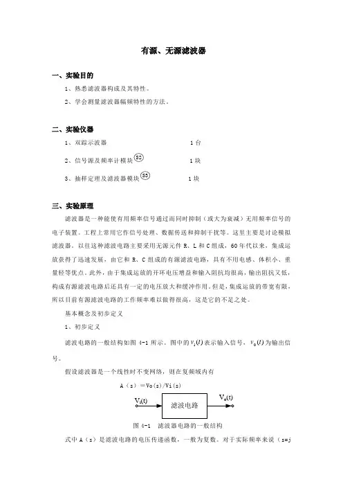
基本概念及初步定义 1、初步定义滤波电路的一般结构如图4-1所示。
图中的)(1t v 表示输入信号,)(0t v 为输出信号。
假设滤波器是一个线性时不变网络,则在复频域内有A (s )=Vo(s)/Vi(s)图4-1 滤波器电路的一般结构式中A (s )是滤波电路的电压传递函数,一般为复数。
对于实际频率来说(s=jω)则有A (j ω)=│A (j ω)│ej φ(ω) (4-1) 这里│A (j ω)│为传递函数的模,φ(ω)为其相位角。
二阶RC 滤波器的传输函数如下表所示:此外,在滤波电路中关心的另一个量是时延τ(ω),它定义为)()()(s d d ωωϕωτ-= (4-2) 通常用幅频响应来表征一个滤波电路的特性,欲使信号通过滤波器的失真很小,则相位和时延响应亦需考虑。
当相位响应φ(ω)作线性变化,即时延响应τ(ω)为常数时,输出信号才可能避免失真。
2.滤波电路的分类对于幅频响应,通常把能够通过的信号频率范围定义为通带,而把受阻或衰减的信号频率范围称为阻带,通带和阻带的界限频率叫做截止频率fc 。
5.二阶无源低通滤波器二阶低通滤波器设计一:实验目的.设计、焊接一个二阶低通滤波器,要求:截止频率为1KHz。
二:实验原理利用电容通高频阻低频的特性,使一定频率范围内的频率通过。
从而设计电路,使得低频率的波通过滤波器。
三:实验步骤1:设计电路,在仿真软件上进行仿真,在仿真电路图上使功能实现。
2:先定电容,挑选合适的电阻,测量电阻的真实值,再到仿真电路替换掉原来的电阻值,不断挑选电阻,找到最逼近实验结果的值3:根据仿真电路进行焊接,完成之后对电路进行功能检测,分别挑选频率为100hz,1khz,10khz的电源进行输入检测,观察输出的波形,并进行实验记录四:实验电路图1.1仿真电路设计图1.4 f=100Hz 时正弦信号实测波形图表1 f=100Hz时实测结果与仿真数据对比表数据项目输入幅值/V 输出幅值/V 衰减/dB 相位差仿真电路169.706 167.869 0.0945 0.018π实测电路0.468 0.440 0.0536 0π分析:由图1.3的仿真波形与图1.4的实测电路波形和表1中的数据可知,输入频率为100Hz的正弦信号时,该信号能够通过,输入输出波形间有较小相位差和较小衰减。
仿真和实测数据间存在误差,误差值较小,在允许范围内。
图1.5 f=1kHz 时正弦信号仿真波形图图1.6 f=300Hz 时正弦信号实测波形图表2 f=1kHz时实测结果与仿真数据对比表数据项目输入幅值/V 输出幅值/V 衰减/dB 相位差仿真电路169.631 121.047 2.931 0.140π实测电路0.480 0.328 3.307 0.120π分析:由图1.5的仿真波形与图1.6的实测电路波形和表2中的数据可知,输入频率为1kHz的正弦信号时,该信号能够通过,输入输出波形间有一定的相位差和衰减。
仿真和实测数据间存在误差,误差值较小,在允许范围内。
图1.7 f=10kHz 时正弦信号仿真波形图图1.8 f=10kHz 时正弦信号实测波形图表3 f=10kHz时实测结果与仿真数据对比表数据项目输入幅值/V 输出幅值/V 衰减/dB 相位差仿真电路169.479 9.878 24.689 0.375π实测电路0.476 0.032 23.449 0.25π分析:由图1.7的仿真波形与图1.8的实测电路波形和表3中的数据可知,输入频率为10kHz的正弦信号时,该信号不能够通过,输入输出波形间有较大的相位差和较大衰减。
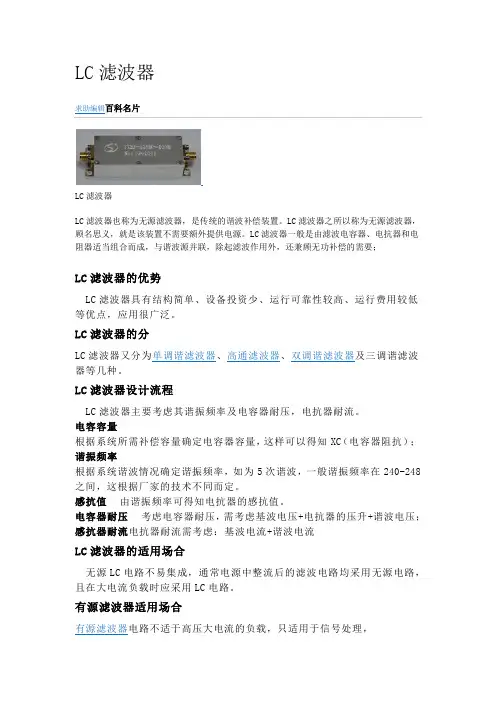
LC滤波器LC滤波器LC滤波器也称为无源滤波器,是传统的谐波补偿装置。
LC滤波器之所以称为无源滤波器,顾名思义,就是该装置不需要额外提供电源。
LC滤波器一般是由滤波电容器、电抗器和电阻器适当组合而成,与谐波源并联,除起滤波作用外,还兼顾无功补偿的需要;LC滤波器的优势LC滤波器具有结构简单、设备投资少、运行可靠性较高、运行费用较低等优点,应用很广泛。
LC滤波器的分LC滤波器又分为单调谐滤波器、高通滤波器、双调谐滤波器及三调谐滤波器等几种。
LC滤波器设计流程LC滤波器主要考虑其谐振频率及电容器耐压,电抗器耐流。
电容容量根据系统所需补偿容量确定电容器容量,这样可以得知XC(电容器阻抗);谐振频率根据系统谐波情况确定谐振频率,如为5次谐波,一般谐振频率在240-248之间,这根据厂家的技术不同而定。
感抗值由谐振频率可得知电抗器的感抗值。
电容器耐压考虑电容器耐压,需考虑基波电压+电抗器的压升+谐波电压;感抗器耐流电抗器耐流需考虑:基波电流+谐波电流LC滤波器的适用场合无源LC电路不易集成,通常电源中整流后的滤波电路均采用无源电路,且在大电流负载时应采用LC电路。
有源滤波器适用场合有源滤波器电路不适于高压大电流的负载,只适用于信号处理,LC滤波器的安装注意事项LC滤波器的不能存在电磁耦合路径LC滤波器不正确的安装方式(一)此两种都是不正确的安装方式,问题的本质在于,滤波器的输入端电线和它的输出端电线之间存在有明显的电磁耦合路径。
这样一来,存在于滤波器某一端的EMI信号会逃脱滤波器对它的抑制,不经过滤波器的衰减而直接耦合到滤波器的另一端去。
另外,如上述两种把LC滤波器都是安装在设备屏蔽的内部,设备内部电路及元件上的EMI 信号会因辐射在滤波器的(电源)端引线上生成EMI 信号而直接耦合到设备外面去,使设备屏蔽丧失对内部元件和电路产生的EMI 辐射的抑制。
当然,如果滤波器(电源)上存在有EMI 信号,也会因辐射而耦合到设备内部的元件和电路上,从而破坏滤波器和屏蔽对EMI 信号的抑制作用。
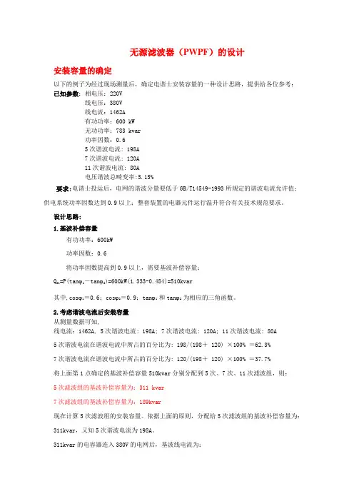
无源滤波器(PWPF)的设计安装容量的确定以下的例子为经过现场测量后,确定电谐士安装容量的一种设计思路,提供给各位参考:已知参数:相电压:220V线电压:380V线电流:1462A有功功率:600 kW无功功率:783 kvar功率因数:0.65次谐波电流: 198A7次谐波电流: 120A11次谐波电流: 80A电压谐波总畸变率:5.15%要求:电谐士投运后,电网的谐波分量要低于GB/T14549-1993所规定的谐波电流允许值;供电系统功率因数达到0.9以上;整套装置的电器元件运行温升符合有关技术规范要求。
设计思路:1.基波补偿容量有功功率:600kW功率因数:0.6将功率因数提高到0.9以上,需要基波补偿容量:Q C1=P(tanϕ1-tanϕ2)=600kW(1.333-0.484)=510kvar其中,cosϕ1=0.6;cosϕ2=0.9;tanϕ1 和tanϕ2 为相应的三角函数。
2.考虑谐波电流后安装容量从测量数据可知,线电流:1462A, 5次谐波电流: 198A; 7次谐波电流: 120A; 11次谐波电流: 80A5次谐波电流在谐波电流中所占的百分比为: 198/(198+ 120) ×100% =62.3%7次谐波电流在谐波电流中所占的百分比为: 120/(198+ 120) ×100% =37.7%将上面第1点确定的基波补偿容量510kvar分别分配到5次、7次、11次滤波组,则:5次滤波组的基波补偿容量为:311 kvar7次滤波组的基波补偿容量为:189kvar现在计算5次滤波组的安装容量。
依据上面的原则,分配给5次滤波组的基波补偿容量为:311kvar,又知5次谐波电流为198A。
311kvar的电容器连入380V的电网后,基波线电流为:I =U Q⨯3=311400⨯= 448.07A容量和电流、容抗的关系式如下:XI cQ ⨯=2对于基波: X c Q I1121⨯=...............................(1) 对于5次谐波:X c Q I5525⨯= (2)其中,X c 1= 5×X c 5由上面的两个式子相比,可得198A 的5次谐波电流注入电容器时的谐波容量Q 5: Q 5= 311 × 1982/(448.92×5) =12kvar所以,在380V 下,5次滤波组的安装容量为: Q 1+Q 5=311 +12=323kvar考虑到串联电抗器后,电容器的电压会升高,这里选额定电压为480V 的电容器。
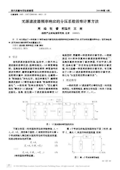
一、滤波器影象参数法的设计滤波器是一种典型的选频电路,在给定的频段内,理论上它能让信号无衰减地通过电路,这一段称为通带外的其他信号将受到很大的衰减,具有很大衰减的频段称为阻带,通带与阻带的交界频率称为截止频率,对滤波器的基本要求是:(1)通带内信号的衰减要小,阻带内信号的衰减要大,由通带过渡到阻带的衰减特性陡直上升;(2)通带内的特性阻抗要恒为常数,以便于阻抗匹配。
滤波器的分类如下:滤波器:1、无源滤波器2、有源滤波器,无源滤波器又分为:RC滤波器和LC滤波器,RC滤波器又分为:1 低通RC滤波器 2 高通RC滤波器 3 带通RC滤波器LC滤波器又分为:1 低通LC滤波器2 高通LC滤波器3 带阻LC滤波器4 带通LC滤波器有源滤波器又分为:1 有源高通滤波器 2 有源低通滤波器 3 有源带通滤波器 4 有源带阻滤波器目前滤波器的分析和设计方法有两种:一是影像参数分析法,二是工作参数分析法(又称综合法)。
前者设计简单,易于掌握,但这种滤波器的实测滤波特性与理论上的预定特性差别较大,在通带内又不能取得良好阻抗匹配,很难满足对滤波特性精度高的要求;后者是以网络综合理论为基础的分析方法,它选区找出与理想滤波特性相近似的网络函数,然后根据综合方法实现该网络函数,由这种方法设计出来的滤波器,实测的滤波特性与理论预定特性十分接近,所以适合于高精度的滤波器设计要求。
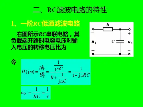
1.RC滤波器[见表一]1010=1/6.28×10101010×10=240pFC2≈1/6.28×15×10×(10+5)10≈680pF2.LC滤波器LC滤波器适用于高频信号的滤波,它由电感L和电容C所组成,由于感抗随频率增加而增加,而容抗随频率增加而减小,因此LC低通滤波器的串臂接电感,并臂接电容,高通滤波器的L、C位置,则与它相反,通常,LC滤波器有两类,一是定K式LC滤波器,二是m推演式LC 滤波器。
一阶二阶无源所有滤波器正确设计滤波器是电子系统中常见的重要组件,它能够去除不需要的信号成分或频率,并保留感兴趣的信号。
滤波器设计的目标是在给定频率范围内实现所需的频率响应,同时具有稳定性和较小的幅度失真。
一阶和二阶滤波器是最简单且常用的滤波器设计类型,下面将介绍一阶低通滤波器、一阶高通滤波器、一阶带通滤波器、二阶低通滤波器和二阶高通滤波器的设计原理和步骤。
一、一阶低通滤波器(RC滤波器)一阶低通滤波器能够将高于截止频率的信号成分削弱或消除。
RC滤波器由一个电阻和一个电容组成,因此也称为RC电容滤波器。
设计步骤如下:1. 确定所需的截止频率fc。
2. 计算电容C的值,公式为C = 1 / (2πfc)。
3.选择一个适当的电阻R值,可以根据需要来调整输出的阻抗。
4.连接电容和电阻,将输入信号与地相连,输出信号从电容连接点获得。
二、一阶高通滤波器(RL滤波器)一阶高通滤波器能够削弱或消除低于截止频率的信号成分。
RL滤波器由一个电阻和一个电感组成。
设计步骤如下:1. 确定所需的截止频率fc。
2. 计算电感L的值,公式为L = 1 / (2πfc)。
3.选择一个适当的电阻R值,可以根据需要来调整输出的阻抗。
4.连接电感和电阻,将输入信号与地相连,输出信号从电阻连接点获得。
三、一阶带通滤波器(RLC滤波器)一阶带通滤波器能够选择性地通过一定范围内的频率信号。
RLC滤波器由一个电阻、一个电感和一个电容组成。
设计步骤如下:1. 确定所需的中心频率fc和带宽BW。
2. 计算电感L和电容C的值,公式为L = 1 / (2πfc) 和 C = 1 / (2πfcBW)。
3.选择一个适当的电阻R值,可以根据需要来调整输出的阻抗。
4.连接电感、电容和电阻,将输入信号与地相连,输出信号从电阻连接点获得。
四、二阶低通滤波器(RLC滤波器)二阶低通滤波器能够更好地削弱或消除高于截止频率的信号成分。
RLC滤波器由两个电阻、一个电感和一个电容组成。
哈尔滨理工大学实验报告课程名称:信号与系统实验实验名称:无源和有源滤波器设计班级学号姓名指导教师2020 年6 月7 日教务处印制一、实验预习(准备)报告1、实验目的1.了解 RC 无源和有源滤波器的种类、基本结构及其特性;2.分析和对比无源和有源滤波器的滤波特性;3.掌握滤波器的设计方法并完成设计和仿真。
2、实验相关原理及内容1、滤波器是对输入信号的频率具有选择性的一个二端口网络,它允许某些频率(通常是某个频带范围)的信号通过,而其它频率的信号受到衰减或抑制,这些网络可以由RLC 元件或RC 元件构成的无源滤波器,也可以由RC 元件和有源器件构成的有源滤波器。
2、根据幅频特性所表示的通过或阻止信号频率范围的不同,滤波器可分为低通滤波器(LPF)、高通滤波器(HPF)、带通滤波器(BPF)和带阻滤波器(BEF)四种。
把能够通过的信号频率范围定义为通带,把阻止通过或衰减的信号频率范围定义为阻带。
而通带与阻带的分界点的频率ωc 称为截止频率或称转折频率。
图1-1 中的|H(jω)|为通带的电压放大倍数,ω0为中心频率,ωcL和ωcH分别为低端和高端截止频率。
图1-1 各种滤波器的理想频幅特性3、图 1-2 所示,滤波器的频率特性 H(jω)(又称为传递函数),它用下式表示H(jω)=u2=A(ω)∠θ(ω)u1(3-1)式中 A(ω)为滤波器的幅频特性,θ(ω)为滤波器的相频特性。
它们都可以通过实验的方法来测量图 1-2 滤波器。
图 1-2 滤波器模型图四种滤波器的实验线路如图 1-3 所示:图 1-3 各种滤波器的实验线路图3、实验方法及步骤设计1、滤波器的输入端接正弦信号发生器或扫频电源,滤波器的输出端接示波器或交流数字毫伏表,2、测试无源和有源低通滤波器的幅频特性。
3、无源和有源低通滤波器的仿真设计与幅频特性测试。
(1)测试RC 无源低通滤波器的幅频特性。
用图1-1(a)所示的电路,测试RC 无源低通滤波器的特性。
引 言滤波器是一种二端口网络。
它具有选择频率的特性,即可以让某些频率顺利通过,而对其它频率则加以阻拦,目前由于在雷达、微波、通讯等部门,多频率工作越来越普遍,对分隔频率的要求也相应提高;所以需用大量的滤波器。
再则,微波固体器件的应用对滤波器的发展也有推动作用,像参数放大器、微波固体倍频器、微波固体混频器等一类器件都是多频率工作的,都需用相应的滤波器。
更何况,随着集成电路的迅速发展,近几年来,电子电路的构成完全改变了,电子设备日趋小型化。
原来为处理模拟信号所不可缺少的LC型滤波器,在低频部分,将逐渐为有源滤波器和陶瓷滤波器所替代。
在高频部分也出现了许多新型的滤波器,例如:螺旋振子滤波器、微带滤波器、交指型滤波器等等。
虽然它们的设计方法各有自己的特殊之点,但是这些设计方法仍是以低频“综合法滤波器设计”为基础,再从中演变而成,我们要讲的波导滤波器就是一例。
通过这部分内容的学习,希望大家对复变函数在滤波器综合中的应用有所了解。
同时也向大家说明:即使初看起来一件简单事情或一个简单的器件,当你深入地去研究它时,就会有许多意想不到的问题出现,解决这些问题并把它用数学形式来表示,这就是我们的任务。
谁对事物研究得越深,谁能提出的问题就越多,或者也可以说谁能解决的问题就越多,微波滤波器的实例就能很好的说明这个情况。
我们把整个问题不断地“化整为零”,然后逐个地加以解决,最后再把它们合在一起,也就解决了大问题。
这讲义还没有对各个问题都进行详细分析,由此可知提出问题的重要性。
希望大家都来试试。
第一部分 滤波器设计§1-1 滤波器的基本概念图 1图1 的虚线方框里面是一个由电抗元件L 和C 组成的两端口。
它的输入端1-1'与电源相接,其电动势为E g,内 阻为R1。
二端口网络的输出端2-2' 与负载R2相接,当电源的频率为零(直流) 或较低时,感抗jωL很小,负载R2两端的电压降E2比较大(当然这也就是说负载R2可以得到比较大的功率)。
无源带通滤波器计算概述及解释说明1. 引言1.1 概述本篇长文主要探讨了无源带通滤波器计算的概念、原理及应用。
带通滤波器是一种常见的信号处理工具,可以在特定的频率范围内选择性地传递信号,广泛应用于电子和通信工程领域。
无源带通滤波器具有简单、可靠、低噪声等特点,在实际应用中被广泛采用。
1.2 文章结构本文分为五个部分,除引言外还包括“无源带通滤波器计算”、“实例分析与解释说明”、“结论与讨论”和“结束语”。
在“无源带通滤波器计算”部分中,将介绍滤波器的基本原理、传递函数计算方法以及参数选择与设计考虑。
然后,“实例分析与解释说明”部分将通过具体场景介绍和示例演示来阐明无源带通滤波器的操作步骤和计算结果的解读。
紧接着,“结论与讨论”部分将总结文章中的主要观点和发现,并探讨未来研究方向和应用前景,同时也会提及研究的限制和局限性。
最后,在“结束语”部分,将再次总结全文内容和重要观点,并提出进一步的思考或行动建议,同时向相关人士表示感谢或致以致谢。
1.3 目的本文的目的是为读者提供一个全面而清晰的概述,使其能够了解无源带通滤波器计算的基本原理、计算方法和参数选择。
通过实例分析和解释说明部分,读者还将能够掌握如何在具体应用场景中进行滤波器参数计算和结果解读。
最终,我们希望读者能够对无源带通滤波器有更深入的理解,并在实践中能够灵活运用这一知识。
2. 无源带通滤波器计算2.1 滤波器基本原理无源带通滤波器是一种电子滤波器,通过将特定频率范围内的信号传递,而抑制其他频率的信号。
它由无源元件(如电阻、电容和电感)组成,没有能够放大信号的放大器部分。
其基本原理是利用电路中的无源元件对不同频率的信号产生不同的阻抗,从而选择性地衰减或增强特定频率范围内的信号。
2.2 传递函数计算方法在无源带通滤波器中,传递函数描述了输入和输出之间的关系。
传递函数可以通过计算各个无源元件对信号产生的阻抗来得到。
根据滤波器的类型和设计要求,可以选择不同的传递函数计算方法,例如使用频域法或时域法进行计算。