差分低通滤波器设计21568
- 格式:ppt
- 大小:1.66 MB
- 文档页数:39
Application ReportSLWA053B–November2007–Revised April2010 Design of Differential Filters for High-Speed Signal Chains Ken Chan High Speed-Wireless InfrastructureABSTRACTDifferential filters have many desirable attributes.The task of designing differential filters can seem daunting at first.Single-ended filters designed in any filter design package can be converted to a differential implementation.This application report explores simple conversion techniques for low-pass, high-pass,and band-pass LC filters.1IntroductionDifferential signals have many desirable attributes in high-speed signal chains:namely,common-mode rejection from a balanced signal path and matched filter response,immunity from single-ended component parasitic effects,decoupling the signal from requiring a ground reference,and rejection of even-orderharmonics.However,most LC filter design information,techniques,and software are for single-endedsystems.This application report highlights some simple translations that can be made to convert thesingle-ended designs to fully differential designs.Some examples are used to demonstrate thesetranslations.The design of single-ended passive analog LC filters has been simplified greatly by various pieces ofsoftware that can be obtained freely on the Internet.An Internet search for LC filter design yields many results,any of which can be used for this tutorial.This application report uses ELSIE(i.e.,LC)which is freely available for download from the following link as a trial version with some limitations on filter order and usage.For commercial applications,the fullversion should be purchased.For purposes of this application report,the free version is sufficient./elsiedownload.htmlThe SPICE simulator used in this tutorial is the TINA-TI SPICE simulator which can be downloaded from the Texas Instruments Web site at the following link./docs/toolsw/folders/print/tina-ti.htmlThe full TINA version can be purchased from its vendor for access to its full feature set.2Single-Ended to Differential-Ended Filter Translation:2.1Low-Pass,High-Pass,and Band-Pass Filter ImplementationsThe process of designing a differential filter requires the design of a single-ended filter that meets the filter requirements.Freely available tools may be used to generate a single-ended filter with the desirablefrequency response.The low-pass,high-pass and band-pass differential filter implementations arediscussed in the following sections.The single-ended LC low-pass filter can be converted to a differential filter by repeating and folding the design around GND to create the Vin+and Vin-.The GND is removed and the center capacitor values are recalculated:the C is half-value(sum of two series C).The L in the horizontal parallel series paths are kept the same and the load resistor is doubled(sum of two series R).The process is illustrated inFigure1.1 SLWA053B–November2007–Revised April2010Design of Differential Filters for High-Speed Signal ChainsVinR26L2522Hm R25100WR28L2622Hm 100W22HmR31L2822Hm 100W22Hm WVout-Vin-L322Hm R10100W V OUTV V R2100WL122Hm OUTOUT-WL322Hm R10100W V OUTV V R2100WL122Hm R1200WOUT OUT-Figure 1.Conversion Process From Single-Ended to a Differential FilterFigure 2.Shunt Capacitor Input Low-Pass FilterFigure 3.Series Inductor Low-Pass FilterAll four of these produce the same response as shown in Figure 4.2Design of Differential Filters for High-Speed Signal Chains SLWA053B–November 2007–Revised April 2010WC21.1 nFR10V INOUTV V R2C11.1 nFWOUT OUT-Figure 4.Low-Pass Filter Response for All Four Low-Pass Filters.Similar circuits can be translated for a simple LC high-pass filter.The circuit is folded along the GND point,the vertical series elements are added and the horizontal elements remain the same.This results in doubling the vertical inductors and load,similar to the approach used for the low-pass filters.Figure 5.Series Capacitor Input High-Pass Filter3SLWA053B–November 2007–Revised April 2010Design of Differential Filters for High-Speed Signal ChainsC41.1 nFR6V OUTVVR8C51.1 nFOUTOUT-Figure 6.Shunt Inductor High-Pass FilterAll four high-pass filters have the same frequency response as shown in Figure 7.Figure 7.Frequency Response for All Four High-Pass FiltersThis same principle holds for more complex BPF architectures.The single-ended filter is reflected around the GND point,the GND is removed,and the middle elements are added together.Figure 8provides an example of a third-order Butterworth BPF.4Design of Differential Filters for High-Speed Signal Chains SLWA053B–November 2007–Revised April 2010V INOUTC7 55.5 pFV INOUTC8 55.5 pFV IN-OUT-Figure 8.Example of Third-Order Butterworth Band-Pass FilterFigure 9.Frequency Response of the Third-Order Butterworth Band-Pass FilterFigure 10provides an example of a third-order Cauer BPF with some parallel horizontal elements.Performing the translation results in the network on the right.Both these filters have the same frequency response.5SLWA053B–November 2007–Revised April 2010Design of Differential Filters for High-Speed Signal ChainsV INOUTC18 51 pFC15 185 pFV INOUTV IN-OUT-C22 51 pFC19 185 pFImplementation and Simulation NotesFigure 10.Example of Third-Order Cauer Band-Pass FilterFigure 11.Frequency Response of Third-Order Cauer Band-Pass Filter3Implementation and Simulation NotesNote that all of the networks should show a 6-dB loss due to the voltage divider created by the 100-Ωsource impedance and the 100-Ωtermination impedance.In the voltage source simulation,the transfer function response is determined with the voltage signal source at the input to the source impedance,in effect grouping the response of the source-to-termination resistor divider into the response of the filter.A 2x VCVS was used at the output of the voltage source to account for this fixed 6-dB loss in the resistor divider and to highlight the actual response of the LC network.6Design of Differential Filters for High-Speed Signal Chains SLWA053B–November 2007–Revised April 2010 Summary 4SummaryThe task of designing differential LC filters can seem daunting at first.But by using some basicsingle-ended filter design tools and applying some simple translations,it is possible to design differential LC filters to have the same response as the single-ended filter.The examples in this document haveshown that this method can be applied to any singled-ended LC filter network to produce a passiveequivalent differential filter.7 SLWA053B–November2007–Revised April2010Design of Differential Filters for High-Speed Signal ChainsIMPORTANT NOTICETexas Instruments Incorporated and its subsidiaries(TI)reserve the right to make corrections,modifications,enhancements,improvements, and other changes to its products and services at any time and to discontinue any product or service without notice.Customers should obtain the latest relevant information before placing orders and should verify that such information is current and complete.All products are sold subject to TI’s terms and conditions of sale supplied at the time of order acknowledgment.TI warrants performance of its hardware products to the specifications applicable at the time of sale in accordance with TI’s standard warranty.Testing and other quality control techniques are used to the extent TI deems necessary to support this warranty.Except where mandated by government requirements,testing of all parameters of each product is not necessarily performed.TI assumes no liability for applications assistance or customer product design.Customers are responsible for their products and applications using TI components.To minimize the risks associated with customer products and applications,customers should provide adequate design and operating safeguards.TI does not warrant or represent that any license,either express or implied,is granted under any TI patent right,copyright,mask work right, or other TI intellectual property right relating to any combination,machine,or process in which TI products or services are rmation published by TI regarding third-party products or services does not constitute a license from TI to use such products or services or a warranty or endorsement e of such information may require a license from a third party under the patents or other intellectual property of the third party,or a license from TI under the patents or other intellectual property of TI.Reproduction of TI information in TI data books or data sheets is permissible only if reproduction is without alteration and is accompanied by all associated warranties,conditions,limitations,and notices.Reproduction of this information with alteration is an unfair and deceptive business practice.TI is not responsible or liable for such altered rmation of third parties may be subject to additional restrictions.Resale of TI products or services with statements different from or beyond the parameters stated by TI for that product or service voids all express and any implied warranties for the associated TI product or service and is an unfair and deceptive business practice.TI is not responsible or liable for any such statements.TI products are not authorized for use in safety-critical applications(such as life support)where a failure of the TI product would reasonably be expected to cause severe personal injury or death,unless officers of the parties have executed an agreement specifically governing such use.Buyers represent that they have all necessary expertise in the safety and regulatory ramifications of their applications,and acknowledge and agree that they are solely responsible for all legal,regulatory and safety-related requirements concerning their products and any use of TI products in such safety-critical applications,notwithstanding any applications-related information or support that may be provided by TI.Further,Buyers must fully indemnify TI and its representatives against any damages arising out of the use of TI products in such safety-critical applications.TI products are neither designed nor intended for use in military/aerospace applications or environments unless the TI products are specifically designated by TI as military-grade or"enhanced plastic."Only products designated by TI as military-grade meet military specifications.Buyers acknowledge and agree that any such use of TI products which TI has not designated as military-grade is solely at the Buyer's risk,and that they are solely responsible for compliance with all legal and regulatory requirements in connection with such use. TI products are neither designed nor intended for use in automotive applications or environments unless the specific TI products are designated by TI as compliant with ISO/TS16949requirements.Buyers acknowledge and agree that,if they use any non-designated products in automotive applications,TI will not be responsible for any failure to meet such requirements.Following are URLs where you can obtain information on other Texas Instruments products and application solutions:Products ApplicationsAmplifiers Audio /audioData Converters Automotive /automotiveDLP®Products Communications and /communicationsTelecomDSP Computers and /computersPeripheralsClocks and Timers /clocks Consumer Electronics /consumer-appsInterface Energy /energyLogic Industrial /industrialPower Mgmt Medical /medicalMicrocontrollers Security /securityRFID Space,Avionics&/space-avionics-defenseDefenseRF/IF and ZigBee®Solutions /lprf Video and Imaging /videoWireless /wireless-appsMailing Address:Texas Instruments,Post Office Box655303,Dallas,Texas75265Copyright©2010,Texas Instruments Incorporated。
你需要知道的通信系统中的差分滤波器的设计
当提到通信系统时,比起单端电路,差分电路总是能提供更加优良的性能。
它们具有更高的线性度、抗共模干扰信号性能等。
但是,对于差分电路还是有很多谜团。
某些RF工程师认为很难设计、测试和调试它们。
对于差分滤波器尤其如此。
是时候揭开差分滤波器设计的神秘面纱了。
要做到这一点,我们要从通信系统接收链中的IF级滤波器开始。
我们将介绍基本滤波器的一些重要规格概念、几类常用滤波器的响应、切比雪夫1型滤波器应用,以及如何从单端滤波器设计开始,然后将其转化为差分滤波器设计。
我们还将考察一个差分滤波器设计示例,并讨论有关如何优化差分电路PCB设计的若干要点。
RF信号链应用中差分电路的优点
用户利用差分电路可以达到比利用单端电路更高的信号幅度。
在相同电源电压下,差分信号可提供两倍于单端信号的幅度。
它还能提供更好的线性度和SNR性能。
差分电路对外部EMI和附近信号的串扰具有很好的抗扰性。
这是因为接收的有用信号电压加倍,噪声对紧密耦合走线的影响在理论上是相同的,它们彼此抵消。
差分信号产生的EMI往往也较低。
这是因为信号电平的变化(dV/dt或dI/dt)产生相反的磁场,再次相互抵消。
差分信号可抑制偶数阶谐波。
以下展示了连续波(CW)通过一个增益模块的示例。
当使用一个单端放大器时,如图2所示,输出可表示为公式1和公式2。
当使用一个差分放大器时,输入和输出如图3所示,表示为公式3、公式4、公式5和公式6。
理想情况下,输出没有任何偶数阶谐波,使得差分电路成为通信系统一个更好的选择。
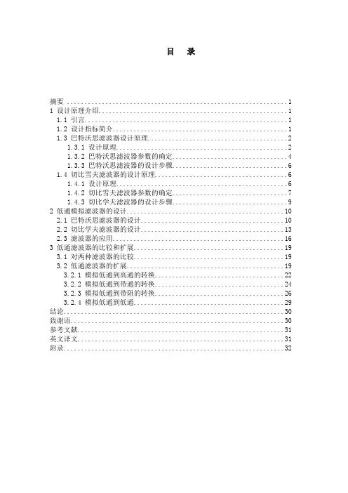
目录摘要 (1)1 设计原理介绍 (1)1.1 引言 (1)1.2 设计指标简介 (1)1.3 巴特沃思滤波器设计原理 (2)1.3.1 设计原理 (2)1.3.2 巴特沃思滤波器参数的确定 (4)1.3.3 巴特沃思滤波器的设计步骤 (6)1.4 切比雪夫滤波器的设计原理 (6)1.4.1 设计原理 (6)1.4.2 切比雪夫滤波器参数的确定 (7)1.4.3 切比学夫滤波器的设计步骤 (9)2 低通模拟滤波器的设计 (10)2.1 巴特沃思滤波器的设计 (10)2.2 切比学夫滤波器的设计 (13)2.3 滤波器的应用 (16)3 低通滤波器的比较和扩展 (19)3.1 对两种滤波器的比较 (19)3.2 低通滤波器的扩展 (19)3.2.1 模拟低通到高通的转换 (22)3.2.2 模拟低通到带通的转换 (24)3.2.3 模拟低通到带阻的转换 (26)3.2.4 模拟低通到低通 (29)结论 (30)致谢语 (30)参考文献 (31)英文译文 (31)附录 (32)2010届电子信息工程专业毕业设计低通模拟滤波器的设计和应用摘要:本文首先介绍了两种设计低通模拟滤波器的方法,然后通过对具体例子应用两种方法进行滤波器的设计,根据设计方法的不同,对得出的结果作比较,总结两种方法各自的特点。
最后通过两个小例子,低通与高通、带通、带阻的转换关系来体现滤波器的应用。
设计主要以巴特沃思原理和切比雪夫原理为基础,以Matlab软件为设计工具,在Matlab 中编程设计出滤波器,并进行幅频特性、相频特性、衰减特性的分析。
Matlab为设计提供了强大的函数库和绘图功能,在应用中同样用Matlab编程实现滤波。
关键词:巴特沃思切比雪夫低通模拟滤波器1 设计原理介绍1.1 引言这个项目主要从以巴特沃思原理和切比雪夫原理为基础,根据技术指标设计出相应的滤波器,通过两种不同的设计方法来达到同样的目标,从设计过程中来比较两种设计方法各自的优势,可以为满足不用的设计要求提供参考。
低通无源滤波器仿真与分析一、滤波器定义所谓滤波器(filter),是一种用来消除干扰杂讯的器件,对输入或输出的信号中特定频率的频点或该频点以外的频率进行有效滤除的电路,就是滤波器,其功能就是得到一个特定频率或消除一个特定频率。
一般可实为一个可实现的线性时不变系统。
二、滤波器的分类常用的滤波器按以下类型进行分类。
1)按所处理的信号:按所处理的信号分为模拟滤波器和数字滤波器两种。
2)按所通过信号的频段按所通过信号的频段分为低通、高通、带通和带阻滤波器四种。
低通滤波器:它允许信号中的低频或直流分量通过,抑制高频分量或干扰和噪声。
高通滤波器:它允许信号中的高频分量通过,抑制低频或直流分量。
带通滤波器:它允许一定频段的信号通过,抑制低于或高于该频段的信号、干扰和噪声。
带阻滤波器:它抑制一定频段内的信号,允许该频段以外的信号通过。
3)按所采用的元器件按所采用的元器件分为无源和有源滤波器两种。
无源滤波器:仅由无源元件(R、L 和C)组成的滤波器,它是利用电容和电感元件的电抗随频率的变化而变化的原理构成的。
这类滤波器的优点是:电路比较简单,不需要直流电源供电,可靠性高;缺点是:通带内的信号有能量损耗,负载效应比较明显,使用电感元件时容易引起电磁感应,当电感L 较大时滤波器的体积和重量都比较大,在低频域不适用。
有源滤波器:由无源元件(一般用R 和C)和有源器件(如集成运算放大器)组成。
这类滤波器的优点是:通带内的信号不仅没有能量损耗,而且还可以放大,负载效应不明显,多级相联时相互影响很小,利用级联的简单方法很容易构成高阶滤波器,并且滤波器的体积小、重量轻、不需要磁屏蔽(由于不使用电感元件);缺点是:通带范围受有源器件(如集成运算放大器)的带宽限制,需要直流电源供电,可靠性不如无源滤波器高,在高压、高频、大功率的场合不适用。
4) 按照阶数来分通过传递函数的阶数来确定滤波器的分类。
三、网络的频率响应在时域中,设输入为)(t x ,输出为)(t y ,滤波器的脉冲响应函数为)(t h 。
目录摘要 (1)1 设计原理介绍 (1)1.1 引言 (1)1.2 设计指标简介 (1)1.3 巴特沃思滤波器设计原理 (2)1.3.1 设计原理 (2)1.3.2 巴特沃思滤波器参数的确定 (4)1.3.3 巴特沃思滤波器的设计步骤 (6)1.4 切比雪夫滤波器的设计原理 (6)1.4.1 设计原理 (6)1.4.2 切比雪夫滤波器参数的确定 (7)1.4.3 切比学夫滤波器的设计步骤 (9)2 低通模拟滤波器的设计 (10)2.1 巴特沃思滤波器的设计 (10)2.2 切比学夫滤波器的设计 (13)2.3 滤波器的应用 (16)3 低通滤波器的比较和扩展 (19)3.1 对两种滤波器的比较 (19)3.2 低通滤波器的扩展 (19)3.2.1 模拟低通到高通的转换 (22)3.2.2 模拟低通到带通的转换 (24)3.2.3 模拟低通到带阻的转换 (26)3.2.4 模拟低通到低通 (29)结论 (30)致谢语 (30)参考文献 (31)英文译文 (31)附录 (32)2010届电子信息工程专业毕业设计低通模拟滤波器的设计和应用摘要:本文首先介绍了两种设计低通模拟滤波器的方法,然后通过对具体例子应用两种方法进行滤波器的设计,根据设计方法的不同,对得出的结果作比较,总结两种方法各自的特点。
最后通过两个小例子,低通与高通、带通、带阻的转换关系来体现滤波器的应用。
设计主要以巴特沃思原理和切比雪夫原理为基础,以Matlab软件为设计工具,在Matlab 中编程设计出滤波器,并进行幅频特性、相频特性、衰减特性的分析。
Matlab为设计提供了强大的函数库和绘图功能,在应用中同样用Matlab编程实现滤波。
关键词:巴特沃思切比雪夫低通模拟滤波器1 设计原理介绍1.1 引言这个项目主要从以巴特沃思原理和切比雪夫原理为基础,根据技术指标设计出相应的滤波器,通过两种不同的设计方法来达到同样的目标,从设计过程中来比较两种设计方法各自的优势,可以为满足不用的设计要求提供参考。
滤波器的模拟和数字滤波器设计技术滤波器是一种能够改变信号频谱的电路或系统。
它可以选择性地通过或者阻断特定频率的信号,以达到滤波的目的。
在现代电子系统中,滤波器扮演着至关重要的角色,被广泛应用于音频处理、通信系统以及图像信号处理等领域。
一、模拟滤波器设计技术模拟滤波器是一种基于模拟电路实现的滤波器。
它采用电阻、电容和电感等元件组成,能够处理连续时间的模拟信号。
模拟滤波器按照频率响应的不同可以分为低通、高通、带通和带阻滤波器。
1. 低通滤波器低通滤波器的频率响应在截止频率以下具有较小的衰减,用于将低频信号通过而滤除高频成分。
常见的低通滤波器有RC低通滤波器和Butterworth低通滤波器等。
设计低通滤波器的关键是确定截止频率和了解所需的衰减特性。
2. 高通滤波器高通滤波器在截止频率以上可以通过较小的衰减,而阻断低频信号。
常见的高通滤波器有RLC高通滤波器和Butterworth高通滤波器等。
高通滤波器的设计也需要确定截止频率和衰减特性。
3. 带通滤波器带通滤波器通过一定范围内的频率信号,而阻断其他频率范围的信号。
它由低通滤波器和高通滤波器串联而成,常见的带通滤波器有二阶和四阶Butterworth带通滤波器。
带通滤波器的设计需要确定通带和阻带的范围。
4. 带阻滤波器带阻滤波器在某一频率范围内具有较小的衰减,而在该范围之外的频率上具有较大的衰减。
它由低通滤波器和高通滤波器并联组成,常见的带阻滤波器有二阶和四阶Butterworth带阻滤波器。
带阻滤波器的设计需要确定通带和阻带的范围。
二、数字滤波器设计技术数字滤波器是一种使用数字算法实现的滤波器,能够对离散时间信号进行处理。
它通常采用差分方程或者快速傅里叶变换(FFT)等算法实现。
1. IIR数字滤波器IIR(Infinite Impulse Response)数字滤波器是一种递归型的数字滤波器。
它的频率响应特性可以通过极点和零点的位置来描述。
常见的IIR数字滤波器有巴特沃斯滤波器、切比雪夫滤波器和椭圆滤波器等。
【最新整理,下载后即可编辑】低通无源滤波器仿真与分析一、滤波器定义所谓滤波器(filter),是一种用来消除干扰杂讯的器件,对输入或输出的信号中特定频率的频点或该频点以外的频率进行有效滤除的电路,就是滤波器,其功能就是得到一个特定频率或消除一个特定频率。
一般可实为一个可实现的线性时不变系统。
二、滤波器的分类常用的滤波器按以下类型进行分类。
1)按所处理的信号:按所处理的信号分为模拟滤波器和数字滤波器两种。
2)按所通过信号的频段按所通过信号的频段分为低通、高通、带通和带阻滤波器四种。
低通滤波器:它允许信号中的低频或直流分量通过,抑制高频分量或干扰和噪声。
高通滤波器:它允许信号中的高频分量通过,抑制低频或直流分量。
带通滤波器:它允许一定频段的信号通过,抑制低于或高于该频段的信号、干扰和噪声。
带阻滤波器:它抑制一定频段内的信号,允许该频段以外的信号通过。
3)按所采用的元器件按所采用的元器件分为无源和有源滤波器两种。
无源滤波器:仅由无源元件(R、L 和C)组成的滤波器,它是利用电容和电感元件的电抗随频率的变化而变化的原理构成的。
这类滤波器的优点是:电路比较简单,不需要直流电源供电,可靠性高;缺点是:通带内的信号有能量损耗,负载效应比较明显,使用电感元件时容易引起电磁感应,当电感L较大时滤波器的体积和重量都比较大,在低频域不适用。
有源滤波器:由无源元件(一般用R 和C)和有源器件(如集成运算放大器)组成。
这类滤波器的优点是:通带内的信号不仅没有能量损耗,而且还可以放大,负载效应不明显,多级相联时相互影响很小,利用级联的简单方法很容易构成高阶滤波器,并且滤波器的体积小、重量轻、不需要磁屏蔽(由于不使用电感元件);缺点是:通带范围受有源器件(如集成运算放大器)的带宽限制,需要直流电源供电,可靠性不如无源滤波器高,在高压、高频、大功率的场合不适用。
4) 按照阶数来分通过传递函数的阶数来确定滤波器的分类。
三、网络的频率响应在时域中,设输入为)(t x ,输出为)(t y ,滤波器的脉冲响应函数为)(t h 。

滤波器设计与实现方法总结滤波器是信号处理中常用的工具,用于降低或排除信号中的噪声或干扰,保留所需的频率成分。
在电子、通信、音频等领域中,滤波器发挥着重要作用。
本文将总结滤波器的设计与实现方法,帮助读者了解滤波器的基本原理和操作。
一、滤波器分类滤波器根据其频率特性可分为低通滤波器、高通滤波器、带通滤波器和带阻滤波器。
它们分别具有不同的频率传递特性,适用于不同的应用场景。
1. 低通滤波器低通滤波器将高频信号抑制,只通过低于截止频率的信号。
常用的低通滤波器有巴特沃斯滤波器、切比雪夫滤波器和椭圆滤波器。
设计低通滤波器时,需要确定截止频率、阻带衰减和通带波动等参数。
2. 高通滤波器高通滤波器将低频信号抑制,只通过高于截止频率的信号。
常见的高通滤波器有巴特沃斯滤波器、切比雪夫滤波器和椭圆滤波器。
设计高通滤波器时,需要考虑截止频率和阻带衰减等参数。
3. 带通滤波器带通滤波器同时允许一定范围内的频率通过,抑制其他频率。
常用的带通滤波器有巴特沃斯滤波器、切比雪夫滤波器和椭圆滤波器。
设计带通滤波器时,需要确定通带范围、阻带范围和通带波动等参数。
4. 带阻滤波器带阻滤波器拒绝一定范围内的频率信号通过,允许其他频率信号通过。
常见的带阻滤波器有巴特沃斯滤波器、切比雪夫滤波器和椭圆滤波器。
设计带阻滤波器时,需要确定阻带范围、通带范围和阻带衰减等参数。
二、滤波器设计方法1. 传统方法传统的滤波器设计方法主要基于模拟滤波器的设计原理。
根据滤波器的频率特性和参数要求,可以利用电路理论和网络分析方法进行设计。
传统方法适用于模拟滤波器设计,但对于数字滤波器设计则需要进行模拟到数字的转换。
2. 频率抽样方法频率抽样方法是一种常用的数字滤波器设计方法。
它将连续时间域的信号转换为离散时间域的信号,并利用频域采样和离散时间傅立叶变换进行设计。
频率抽样方法可以实现各种类型的数字滤波器设计,包括有限冲激响应(FIR)滤波器和无限冲激响应(IIR)滤波器。
模拟电子技术基础知识滤波器的频率选择特性与设计滤波器在模拟电子技术中起着至关重要的作用,它可以对输入信号进行频率分离和处理,从而满足不同应用的需求。
频率选择特性是滤波器设计的核心,它决定了滤波器在不同频率下的响应。
一、频率选择特性的基本原理频率选择特性是指滤波器对不同频率信号的响应程度。
在电子技术中,常用的频率选择特性有低通、高通、带通和带阻四种类型。
1. 低通滤波器(Low-Pass Filter)低通滤波器能够通过低于某个截止频率的信号,而将高于该截止频率的信号削弱或消除。
它常用于信号处理中的平滑和去噪。
2. 高通滤波器(High-Pass Filter)高通滤波器则相反,它允许高于某个截止频率的信号通过,而将低于该截止频率的信号削弱或消除。
高通滤波器常用于信号处理中的边缘检测和某些特殊信号的突变检测。
3. 带通滤波器(Band-Pass Filter)带通滤波器可以允许某个频率范围内的信号通过,并减弱其他频率范围内的信号。
它常用于信号处理中的频带选择和音频处理。
4. 带阻滤波器(Band-Stop Filter)与带通滤波器相反,带阻滤波器能够削弱或消除某个频率范围内的信号,而允许其他频率范围内的信号通过。
带阻滤波器常用于干扰信号的去除和陷波。
二、滤波器的设计与实现滤波器的设计是模拟电子技术中的重要任务之一。
下面以低通滤波器为例,介绍滤波器的设计与实现。
1. 确定滤波器的截止频率根据应用需求,确定滤波器的截止频率。
截止频率是滤波器对信号进行削弱的频率点。
在设计低通滤波器时,需要确定将高于截止频率的信号进行削弱的程度。
2. 选择滤波器的响应类型与阶数根据具体需求,选择滤波器的响应类型和阶数。
常见的低通滤波器响应类型有巴特沃斯(Butterworth)、切比雪夫(Chebyshev)和椭圆(Elliptic)等。
3. 计算滤波器的设计参数根据截止频率、响应类型和阶数,计算滤波器的设计参数,如电阻值、电容值、电感值等。
[导读]模拟滤波器集分为无源滤波器和有源滤波器组成,其中无源滤波器由R、L、C组成,有源滤波器由集成运放和R、C组成,不需要使用电感。
集成运放的开环电压增益和输入阻抗均很高,输出电阻小,构成有源滤波电路后还具有一定的电压放大和缓冲作用几乎所有电子电路中都能看到有源模拟滤波器的身影。
音频系统使用滤波器进行频带限制和平衡。
通信系统设计师使用滤波器调谐特定频率并消除其它频率。
为了使高频信号衰减,所有数据采集系统都在模数转换器(ADC)前面有一个抗锯齿(低通)滤波器,或者在数模转换器(DAC)后面有一个抗镜像(低通)滤波器。
这种模拟滤波还可以在信号到达ADC之前或者离开DAC之后,消除叠加在信号上面的高频噪声。
如果ADC的输入信号超出转换器采样频率的一半,则该信号的大小被可靠地转换;但是,在其变回数字输出时,频率也发生改变。
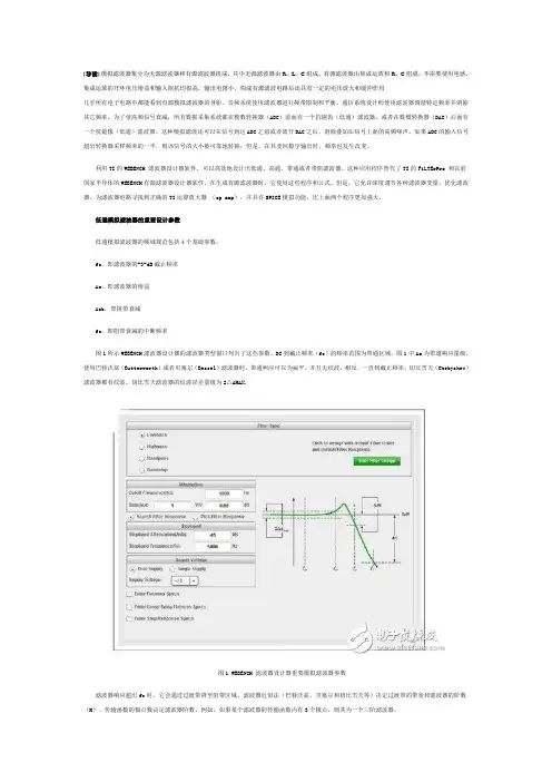
利用TI的WEBENCH 滤波器设计器软件,可以高效地设计出低通、高通、带通或者带阻滤波器。
这种应用程序替代了TI的FiLTErPro 和以前国家半导体的WEBENCH有源滤波器设计器软件。
在生成有源滤波器时,它使用这些程序和公式。
但是,它允许深度调节各种滤波器变量,优化滤波器,为滤波器电路寻找到正确的TI运算放大器(op amp),并具有SPICE模拟功能,比上面两个程序更加强大。
低通模拟滤波器的重要设计参数低通模拟滤波器的频域规范包括4个基础参数:fc,即滤波器的-3-dB截止频率Ao,即滤波器的增益Asb,即阻带衰减fs,即阻带衰减的中断频率图1所示WEBENCH滤波器设计器的滤波器类型窗口列出了这些参数。
DC到截止频率(fc)的频率范围为带通区域。
图1中Ao为带通响应量级。
使用巴特沃兹(Butterworth)或者贝塞尔(Bessel)滤波器时,带通响应可以为扁平,并且无纹波。
相反,一直到截止频率,切比雪夫(Chebyshev)滤波器都有纹波。
切比雪夫滤波器的纹波误差量级为2△AMAX.图1 WEBENCH 滤波器设计器重要模拟滤波器参数滤波器响应超出fc时,它会通过过渡带降至阻带区域。
实验一、继电保护滤波系统设计差分滤波器的设计:f1=0:0.1:2500;subploty=2*abs(sin(3*pi*f1/2400));subplot(2,1,1);plot(f1,y);title('杨先靖fs=2400HZ差分滤波器幅频特性'); xlabel('f');>> ylabel('H(f)');>> subplot(2,1,2);>> f2=0:0.1:2500;>> n=pi/2-3*pi*f2/2400;>> plot(f2,n);>> title('杨先靖fs=2500HZ差分滤波');>> xlabel('f');>> ylabel('phi(f)');加滤波器的设计f1=0:0.1:2500;y=2*abs(cos(3*pi*f1/2400));subplot(2,1,1);plot(f1,y);title('杨先靖fs=2400HZ加法滤波器幅频特性'); xlabel('f');>> ylabel('H(f)');>> subplot(2,1,2);>> f2=0:0.1:2500;>> n= -3*pi*f2/2400;>> plot(f2,n);>> title('杨先靖fs=2500HZ加法滤波器');>> xlabel('f');>> ylabel('phi(f)');实验二、继电保护滤波系统设计积分波器的设计f1=0:0.1:2500;y=2*abs(sin(4*pi*f1/2400))./abs(sin(pi*f1/2400); subplot(2,1,1);plot(f1,y);title('杨先靖fs=2400HZ加法滤波器幅频特性'); xlabel('f');>> ylabel('H(f)');>> subplot(2,1,2);>> f2=0:0.1:2500;>> n= -3*pi*f2/2400;>> plot(f2,n);>> title('杨先靖fs=2500HZ积分滤波器');>> xlabel('f');>> ylabel('phi(f)');级联滤波器:f1=0:0.1:2500;y=4*abs(cos(2*pi*f1/2400)).*abs(sin(4*pi*f1/2400)); subplot(2,1,1);plot(f1,y);title(杨先靖fs=2400HZ级联滤波器幅频特性'); xlabel('f');>> ylabel('H(f)');>> subplot(2,1,2);>> f2=0:0.1:4000;>> n= -3*pi*f2/2400;>> plot(f2,n);>> title('继保fs=2500HZ积分滤波器');>> xlabel('f');>> ylabel('phi(f)');。
差分滤波器布局布线,这8点你必须考虑!当提到通信系统时,比起单端电路,差分电路总是能提供更加优良的性能——它们具有更高的线性度、抗共模干扰信号性能等。
使用差分电路最大的挑战就是抛开它们难于设计、测试和校正的想法,需要仔细观察如何使用差分滤波器。
那么版主问一句,如何使用差分滤波器?你晓得伐?不晓得,就继续往下看,版主简单明了的给你们说说8个需要注意的点儿~1、成对差分走线的长度须相同此规则源自这一事实:差分接收器检测正负信号跨过彼此的点,即交越点。
因此,信号须同时到达接收器才能正常工作。
2、差分对内的走线布线须彼此靠近如果一对中的相邻线路之间的距离大于电介质厚度的2倍,则其间的耦合会很小。
此规则也是基于差分信号相等但相反这一事实,如果外部噪声同等地干扰两个信号,则其影响会互相抵消。
同样,如果走线并排布线,则差分信号在相邻导线中引起的任何干扰噪声都会被抵消。
3、同一差分对内的走线间距在全长范围内须保持不变如果差分走线彼此靠近布线,它们将影响总阻抗。
如果此间距在驱动器与接收器之间变化不定,则一路上会存在阻抗不匹配,导致反射。
4、差分对之间的间距应较宽以使其间的串扰最小。
5、如果在同一层上使用铜皮铺地,应加大从差分走线到铜皮铺地之间的间隙推荐最小间隙为走线宽度的3倍。
6、在靠近差分对内偏斜源处引入少量弯弯曲曲的校正从而降低这种偏斜。
7、差分对布线时应避免急转弯(90°)。
应使用对称布线。
若需要测试点,应避免引入走线分支,而且测试点应对称放置)。
8、就降低对滤波器元件值的要求,减少印刷电路板(PCB)上的调谐工作量而言,寄生电容和电感应尽可能小。
与滤波器设计中的电感设计值相比,寄生电感可能微不足道。
寄生电容对差分IF滤波器更为重要。
IF滤波器设计中的电容只有几pF。
如果寄生电容达到数十分之一pF,滤波器响应就会受到相当大的影响。
为了防止寄生电容影响,一个良好的做法是避免差分布线区域和电源扼流圈下有任何接地或电源层。
低通无源滤波器仿真与分析一、滤波器定义所谓滤波器(filter),是一种用来消除干扰杂讯的器件,对输入或输出的信号中特定频率的频点或该频点以外的频率进行有效滤除的电路,就是滤波器,其功能就是得到一个特定频率或消除一个特定频率。
一般可实为一个可实现的线性时不变系统。
二、滤波器的分类常用的滤波器按以下类型进行分类。
1)按所处理的信号:按所处理的信号分为模拟滤波器和数字滤波器两种。
2)按所通过信号的频段按所通过信号的频段分为低通、高通、带通和带阻滤波器四种。
低通滤波器:它允许信号中的低频或直流分量通过,抑制高频分量或干扰和噪声。
高通滤波器:它允许信号中的高频分量通过,抑制低频或直流分量。
带通滤波器:它允许一定频段的信号通过,抑制低于或高于该频段的信号、干扰和噪声。
带阻滤波器:它抑制一定频段内的信号,允许该频段以外的信号通过。
3)按所采用的元器件按所采用的元器件分为无源和有源滤波器两种。
无源滤波器:仅由无源元件(R、L 和C)组成的滤波器,它是利用电容和电感元件的电抗随频率的变化而变化的原理构成的。
这类滤波器的优点是:电路比较简单,不需要直流电源供电,可靠性高;缺点是:通带内的信号有能量损耗,负载效应比较明显,使用电感元件时容易引起电磁感应,当电感L较大时滤波器的体积和重量都比较大,在低频域不适用。
有源滤波器:由无源元件(一般用R和C)和有源器件(如集成运算放大器)组成。
这类滤波器的优点是:通带内的信号不仅没有能量损耗,而且还可以放大,负载效应不明显,多级相联时相互影响很小,利用级联的简单方法很容易构成高阶滤波器,并且滤波器的体积小、重量轻、不需要磁屏蔽(由于不使用电感元件);缺点是:通带范围受有源器件(如集成运算放大器)的带宽限制,需要直流电源供电,可靠性不如无源滤波器高,在高压、高频、大功率的场合不适用。
4)按照阶数来分通过传递函数的阶数来确定滤波器的分类。
三、网络的频率响应在时域中,设输入为)(ty,滤波器的脉冲响应函数为)(th。
最新的消费电子产品,如电视机、机顶盒或手机,都能相互连接在一起,或者至少都配备高速度数据接口。
最终消费者最常用的接口是USB或HDMI/MHL高清多媒体接口,但是还有最终消费者看不到的然而对于设计人员却同等重要的内部接口,例如,新出现的MDDI或MIPI接口,这些内部接口用于连接电路板上不同的模块或功能。
例如,我们不能忽视手机相机传感器或AMOLED显示平板与手机主板的连接改用差分数据线而弃用并行数据线的发展趋势,因为差分数据传输的优点是可以提高数据速率和显示器分辨率...显然,这些新接口正在形成一个新的富有挑战性的环境,同时加大了ESD和EMI现象对电子产品设计的威胁。
当然,传统的EMI低通滤波器,如RC滤波器或LC滤波器,将很快达到滤波器的极限值,因此为适应这些新的应用发展趋势,我们必须开发新一代保护芯片。
ECMF新系列保护芯片是以高性能滤波器享誉业界的意法半导体为满足最新的超高速差分信号滤波和ESD保护要求而专门设计的新一代保护产品。
过去,ESD保护或EMI滤波功能以使用RC或LC解决方案为主,例如LTTC 或硅芯片。
但是,数据速率更高的总线的问世,以及差分信号传输替代并行总线的发展趋势,自然迫使设计人员提高整个系统的EMC抗干扰性,寻求新的解决方案。
毋庸置疑,考虑到LC或RC滤波器是由电感或电阻与接地电容器组成,特别是内在电容效应本身将会影响信号的完整性,这两类滤波器将无法适应数据总线不断提高速率的趋势。
因此,只要抑制电容即可避免滤波器出现电容效应;但是这种方法意味丧失滤波器芯片的滤波属性。
当数据速率提高到每秒几百兆位以上时,这种方法是一个进退维谷的问题。
CMF滤波器又称共模滤波器,是解决这个进退两难问题的好办法,不仅支持受最高的数据速率,还是差分信号传输技术如USB、HDMI和MIPI的最佳保护方案。
高速USB 2.0接口利用差分信号方法在两条数据线上传输数据,最高传输速率达到480 Mbps。