ad9851对比VHDL信号发生器
- 格式:doc
- 大小:2.22 MB
- 文档页数:96

目录摘要 —————————————————————————2 创新之处 ———————————————————————2 关键词 ————————————————————————2 引言 —————————————————————————2 系统工作原理 —————————————————————3 直接数字频率合成 ———————————————————4 DDS 基本原理及性能特点 —————————————————5 采用 DDS 的 AD9851 ———————————————————6 AD9851 的原理 —————————————————————7 AD9851 在信号源中的应用 ————————————————8 AD9851 在本系统的应用电路 ———————————————9 低通滤波器(LPF) ——————————————————10 锁相环频率合成 ———————————————————11 锁相环频率合成 MC145151 在本电路中的应用 ————————12 压控振荡器(VCO) ———————————————————12 缓冲放大器 ——————————————————————13 单片机控制的整体电路 —————————————————14 功率放大 ———————————————————————15 本系统的软件设计 ———————————————————15 总调试 ————————————————————————25 结束语 ————————————————————————25 DDS 短波信号发生器技术指标 ——————————————26 所采用的仪器设备 ———————————————————26 所用软件 ———————————————————————26 参考文献 ———————————————————————26 参考网站 ———————————————————————271DDS 短波信号发生器摘要: 本文主要介绍的是采用直接数字频率合成的短波信号发生器, 它 主要以微电脑控制部分、直接数字频率合成(DDS)部分、数字锁相 环频率合成部分、背光液晶显示部分、功率放大部分等组成。
基于AD9851的正弦信号发生器设计1 引言直接数字频率合成DDS(Direct Digital Syndaesis)是实现数字化的一项关键技术,广泛应用于电信与电子仪器领域DDS通常是在CPLD或FPGA内设置逻辑电路实现的,但由于DDS 输出受到D/A转换器的速率及D/A转换后I/V转换中运放的带宽增益和响应时间的限制,CPLD和FPGA内部实现方案在高频段信号幅值已不稳定。
因此,这里介绍一种基于DDS器件AD9851的信号发生器设计方案。
2 AD9851简介AD9851是ADI公司采用先进CMOS技术生产的具有高集成度的直接数字频率合成器。
该器件频带宽、频率与相位均可控,内部频率累加器和相位累加器相互独立,32位调频字使得其在180 MHz的系统时钟下输出频率可达0.04 Hz的高分辨率。
设相位累加器的位数为N,相位控制字的值为FK,频率控制字的位数为M,频率控制字的值为FM,内部工作时钟为FC,最终合成信号的频率F相位和θ分别为:F=FMFC/2N,θ=2πFN/2MAD9851的最高工作时钟为180 MHz,实际电路中,外部晶体振荡器的频率为25 MHz,由经内部集成的6倍频器和高速比较器得到150 MHz的时钟信号,这样可减小高频辐射,提高系统的电磁兼容能力。
AD9851内部集成高速DDS和10 bit高速A/D转换器,故无需D/A 转换和I/V,转换等容易影响DDS输出的单元。
3 系统总体设计方案图1为系统设计框图。
为了产生调制信号,需要在FPGA内部实现低频段的DDS模块以产生正弦波(模拟调制AM和FM)和二进制基带码(数字调制ASK/FSK/PSK)。
由于AD9851输出的正弦信号存在谐波,因此需加一个无源滤波器滤波。
由于无源滤波的衰减特性,为使信号源的最终输出信号幅值稳定,系统需加一级AGC电路。
PGA程控放大器采用DAC7611作为基准控制输出信号的幅度。


电赛总结(四)——波形发⽣芯⽚总结之AD9851⼀、特性参数1、180 MHz时钟速率参考时钟具有6倍倍乘器。
芯⽚具有⾼性能10位DAC和⾼速滞后⽐较器2、+2.7 V⾄+5.25 V单电源⼯作3、正常输出⼯作频率范围为 0~72MHz ;4、具有6倍频,所以只要30MHz的时钟供给即可。
⼆、功能管脚图三、管脚说明管脚名称功能D0–D78位数据输⼊. 数据端⼝,⽤于装载32位的频率控制字和8位相位控制字。
D7为最⾼位,D0=最低位D7, 25引脚, 也作为40位控制字串⾏输⼊引脚PGND6倍参考时钟倍乘器地PVcc6倍参考时钟倍乘器电源W-CLK字装⼊信号,上升沿有效FQ-UD频率更新控制信号,时钟上升沿确认输⼊数据有效FREFCLOCK外部参考时钟输⼊,脉冲序列可直接或间接地加到6倍参考时钟倍乘器上。
在直接⽅式中,输⼊频率即是系统时钟;在6倍参考时钟倍乘器⽅式,系统时钟为倍乘器输出AGND模拟地AVDD模拟电源(+5V)DGND数字地DVDD数字电源(+5V)RSET DAC外部参考电阻连接端VOUTN内部⽐较器负向输出端VOUTP内部⽐较器正向输出端VINN内部⽐较器的负向输⼊端VINP内部⽐较器的正向输⼊端DACBP DAC旁路连接端IOUTB“互补”DAC输出IOUT内部DAC输出端RESET复位端。
低电平清除DDS累加器和相位延迟器为0Hz和0 相位,同时置数据输⼊为串⾏模式以及禁⽌6倍参考时钟倍乘器⼯作四、外围电路PCB原理图五、STM32F103驱动程序#ifndef __AD9851_H#define __AD9851_H#include "stm32f10x.h"#include "gpio.h"#define ad9851_Clk Pin10#define ad9851_FQ_UD Pin11#define ad9851_Rst Pin12#define ad9851_D0 Pin2#define ad9851_D1 Pin3#define ad9851_D2 Pin4#define ad9851_D3 Pin5#define ad9851_D4 Pin6#define ad9851_D5 Pin7#define ad9851_D6 Pin8#define ad9851_D7 Pin9void ad9851_write_dds(unsigned long dds);void ad9851_init(void);void ad9851_writefrq(unsigned long freq);#endif /* __DAC_H */#include "ad9851.h"#include "pbdata.h"#include "math.h"unsigned char phase_word = 0x00; //相位控制字,使⽤低五位unsigned char power_down = 0x00; //低功耗模式unsigned char mult = 0x01; //六倍频开关unsigned char ww[5] = {0x09,0x0E,0x38,0xE3,0xBE};unsigned long freq,set_value;void ad9851_init(void){set_out(GPIOG,ad9851_Clk | ad9851_FQ_UD | ad9851_Rst | ad9851_D0 | ad9851_D1 | ad9851_D2 | ad9851_D3 | ad9851_D4 | ad9851_D5 |ad9851_D6 | ad9851_D7 ); set_outH(GPIOG,ad9851_Rst);delay_ms(10);set_outL(GPIOG,ad9851_Rst);delay_ms(10);}void ad9851_write_dds(unsigned long dds){unsigned char i;ww[0] = (phase_word << 3) | power_down << 2 | mult;ww[1] = (dds >> 24) & 0xff;ww[2] = (dds >> 16) & 0xff;ww[3] = (dds >> 8) & 0xff;ww[4] = dds & 0xff;set_outL(GPIOG,ad9851_FQ_UD);for(i=0;i<5;i++){set_outL(GPIOG,ad9851_Clk);set_outH(GPIOG,ww[i] << 2);set_outL(GPIOG,((~ww[i]) << 2) & 0x3fc);delay_us(10);set_outH(GPIOG,ad9851_Clk);delay_us(10);}set_outH(GPIOG,ad9851_FQ_UD);delay_us(10);set_outL(GPIOG,ad9851_FQ_UD);}void ad9851_writefrq(unsigned long freq){unsigned long dds;dds = freq;ad9851_write_dds(dds);}。


基于DDS芯片AD9951的精密信号发生器设计摘要直接数字频率合成(Direct Digital Frequency Synthesis简称DDS)是近年来迅速发展起来的一种新的频率合成方法。
而AD9951是美国模拟器件公司(ADI)最新推出的高集成度DDS芯片。
本设计采用该芯片,以AT89S52单片机为控制,采用AT24C02来存储重要的系统数据,由1602点阵式字符型液晶显示模块作为显示器,并加上一个小键盘构成了精密信号发生器。
要求其输出频率范围为0~160MHz、最小步进为10Hz或者1Hz、输出信号幅度大于0.3Vp-p、杂散小、有掉电数据保持功能。
文中详细介绍了DDS的工作原理以及该信号发生器的软、硬件设计方案,并给出了具体的程序设计。
指标关键词:直接数字频率合成(DDS)、AD9951、AT89S52、信号发生器、频率控制字直接数字频率合成(Direct Digital Frequency Synthesis简称DDS)是近年来迅速发展起来的一种新的频率合成方法,广泛应用于通讯、导航、雷达、遥控遥测、电子对抗以及现代化的仪器仪表工业等领域。
而AD9951是美国模拟器件公司(ADI)最新推出的高品质、高集成度DDS芯片。
本设计采用该DDS芯片作为核心元件,以AT89S52单片机为主控器件、并辅以AT24C02存储重要的系统数据、1602点阵式字符型液晶显示模块作为显示器,构成了一种精密的DDS信号发生器。
文中详细介绍了DDS的工作原理以及该精密信号发生器的软、硬件设计方法,并给出了具体的程序设计方案。
设计出的信号发生器,输出频率范围为0~160MHz、最小步进为10Hz或者1Hz、输出信号幅度大于0.3Vp-p、杂散小。
关键词:直接数字频率合成(DDS)、AD9951、AT89S52、信号发生器、频率控制字该芯片能以早期DDS 1/10的功耗提供速度高达400 MHz 的内部时钟,而合成频率高达160 MHz。
基于DDS芯片AD9851的信号发生器摘要设计了一种以单片机AT89S52+AD9851为核心的信号发生器,AD9851是美国模拟器件公司采用先进的DDS技术生产的高集成度频率合成单片集成芯片。
由该芯片构成的信号发生器的输出频率范围为0—72MHZ,频率步进可调,最小步进为1HZ、精度为1HZ、输出信号幅度大于0.3Vp-p、杂散小等优点。
文中介绍了DDS的基本原理和AD9851的功能特性以及其控制方式,提出了一种计算频率控制字的算法,最后给出了该信号发生器的硬件结构和软件设计方法。
关键词:DDS AD9851 AT89S52 控制字算法The design of signal generator with AD9851Abstract:Design a signal generator adopted Microcontroller AT89S52+AD9851 as core. The AD9851 is a highly integrated device that uses advanced direct digital synthesizer (DDS ) technology produced by Analog Devices Corporation. The Devices can generating a resultant frequency of up to 72 MHZ and can control. The minimum step can achieve 1HZ . This paper introduces the basic elements of DDS. The function, characteristic and mode for operating of AD8951. At the end of this essay I will display the hardware and software structures of the signal generator formed by the device I mentioned.Keyboards:DDS AD8951AT89S52 control word arithmetic1、前言信号发生器是实验室不可缺少的仪器之一,设计信号发生器的一个关键问题是怎样获得稳定,准确,连续可调的频率输出,解决这一问题的一个较好的方法就是使用频率合成技术。
AD9851信号发生器电路图原理本文基于直接数字频率合成(DDS)原理,采用AD9851型DDS器件设计一个信号发生器,实现50Hz~60MHz范围内的正弦波输出。
通过功率放大,在50Ω负载的情况下,该信号发生器在50Hz~10MHz范围内输出稳定正弦波,电压峰峰值为0~5V±0.3V。
0引言直接数字合成(Direct Digital Synthesis—DDS)是近年来新的电子技术。
单片集成的DDS产品是一种可代替锁相环的快速频率合成器件。
DDS是产生高精度、快速变换频率、输出波形失真小的优先选用技术。
DDS以稳定度高的参考时钟为参考源,通过精密的相位累加器和数字信号处理,通过高速D/A变换器产生所需的数字波形(通常是正弦波形),这个数字波经过一个模拟滤波器后,得到最终的模拟信号波形。
DDS系统一个显著的特点就是在数字处理器的控制下能够精确而快速地处理频率和相位。
除此之外,DDS的固有特性还包括:相当好的频率和相位分辨率(频率的可控范围达μHz级,相位控制小于0.09°),能够进行快速的信号变换(输出DAC的转换速率百万次/秒)。
1AD9851集成芯片简介AD9851是在AD9850的基础上,做了一些改进以后生成的具有新功能的DDS芯片。
AD9851相对于AD9850的内部结构,只是多了一个6倍参考时钟倍乘器,当系统时钟为180MHz时,在参考时钟输入端,只需输入30MHz的参考时钟即可。
AD9851是由数据输入寄存器、频率/相位寄存器、具有6倍参考时钟倍乘器的DDS芯片、10位的模/数转换器、内部高速比较器这几个部分组成。
其中具有6倍参考时钟倍乘器的DDS芯片是由32位相位累加器、正弦函数功能查找表、D/A变换器以及低通滤波器集成到一起。
这个高速DDS芯片时钟频率可达180MHz,输出频率可达70MHz,分辨率为0.04Hz。
AD9851可以产生一个频谱纯净、频率和相位都可编程控制且稳定性很好的模拟正弦波,这个正弦波能够直接作为基准信号源,或通过其内部高速比较器转换成标准方波输出,作为灵敏时钟发生器来使用。
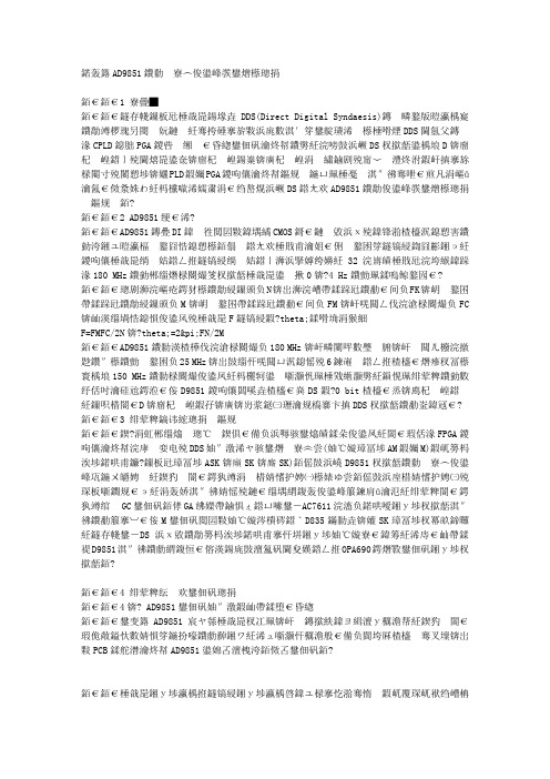
VolumeHAMRADIOINDIAHAMRADIOINDIA Direct Digital Synthesizer for Amateur Bands 1 HAMRADIOINDIA DDS VFO for Amateur BandsHAMRADIOINDIA contact@HAMRADIOINDIAChapter Direct Digital SynthesizerVFO for Amateur BandsA stable multi band HF transceiver is a dream of every ham. The first step to this is to make a multi band stable VFO. But it is very difficult to get stability in ordinary LC VFO at higher frequencies. The Advanced DDS technology helps you to become your dream true. This project used a PIC microcontroller – A range of microcontroller produced by Microchip Inc. in this application, PIC16F628 and AD9851 “a complete DDS synthesizer chip” from Analog Devices.PICThe PIC16F628 is an 18-Pin microcontroller with 2K byte program memory, it is a FLASH-based and a member of the versatile PIC16CXX family of low-cost, high-performance, CMOS, fully-static, 8-bit microcontrollers. PIC16F62X devices have special features to reduce external components, thus reducing system cost, enhancing system reliability and reducing power consumption.DDSThe AD9851 is a highly integrated device that uses advanced DDS technology to form a digitally programmable frequency synthesizer. AD9851 generates a stable frequency and phase-programmable digitized analog output sine wave. This sine wave can be used directly as a frequency source with an output tuning resolution of approximately 0.04 Hz with a 180 MHz system clock. The AD9851 contains 6 X REFCLK Multiplier circuit that eliminates the need for a high frequency reference oscillator.Figure 1. Basic DDS Block Diagram2HAMRADIOINDIAThe basic block diagram is shown in Figure 1. The frequency out put can be calculated using the following formulaeFout = (∆ Phase X Syst em Clock)/ 2 ^ 32Where:∆ Phase = decimal value of 32 bit tuning wordSystem Clock = REFCLK frequency in MHz or 6 X REFCLK frequency(in MHz) if the 6 X REFCLK Multiplier is enabledFout = Output frequency of DDS in MHzThe DDS circuitry is basically a digital frequency divider function whose incremental resolution is determined by the frequency of the system clock, and N (number of bits in the tuning word). The phase accumulator is a variable-modulus counter that increments the number stored in it each time it receives a clock pulse. When the counter reachesfull-scale it wraps around, making the phase accumulator’s output phase-continuous. The frequency tuning word sets the modulus of the counter, which effectively determines the size of the increment (∆P hase) that will be added to the value in the phase accumulator on the next clock pulse. The larger the added increment, the faster the accumulator wraps around, which results in a higher output frequency.Figure 2. Output Spectrum of DDSIn the example shown in Figure 2, the system clock is 100 MHz and the output frequency set to 20 MHz. A low pass filter is essential to remove unwanted images. A good rule-of-thumb is limiting the output frequency to 1/3rd of System Clock frequency. One can use the other images also with help of a good band pass filter. Note that these images are not harmonics and it keeps a 1:1 relation with the fundamental frequency, i.e. if fundamental frequency increased 1 Hz then the image frequency also shifted 1 Hz.3HAMRADIOINDIAOperational Features1. Dual VFO, i.e. VFO A and VFO B facilities.2. Up to 20 RX frequency storage on memory3. The Software allows 2 modes of operation,a. VFO modeb. Memory mode4. Keypad frequency entry5. Step size can be changed from 1Hz to MHz range.6. RIT facility.7. Save to any MEM and copy to any VFO from MEM is possible.8. LSB/USB/CW modes9. Allows -Ve and +Ve IF OFFESTS10. Calibration screen for changing all the setup screens including Chiptype and System Clock Frequency.11. Signal Generator mode.12. Time out function for ignoring any wrong entry13. Low cost mechanical encoder is used14. A 2 x 16 line LCD display used for display freq and other messages Construction notes.The opto-coupler 4N35 is isolating the PTT from the circuit. To change frequency of the DDS, Keypad and Mechanical Rotary encoder are provided. Another six push button switches are used for managing other functions of the VFO. An ordinary keypad used in telephones, which is easily available from the local market is used. If the Mechanical encoder is not available one can use the encoder found in the “Scroll Mouse”. The scroll mouse contains two optical sensors and one mechanical encoder inside it. You can easily remove the mechanical encoder from the mouse and fit it to the front panel of your radio.DDS Chip AD9851BRS/AD9850BRS comes with SSOP package, it is somewhat difficult to solder for a home brewer. Seek the help of a service people to solder this chip to board is an alternative. May be one can try the method Peter Rhodes, G3XJP, in his article AN557 (). He solders this chip to a 24DIP socket using a short wire leads. But this method is not supported by the PCB design shown here. Or one can contact the local mobile phone servicing people to get the chip soldered to PCB.4HAMRADIOINDIAFigure 3. Dimensions of AD9851BRSA 2 line x 16 LCD with or without R/W pin (software use delays rather than busy checks) is used to display VFO frequency and other messages. The LCD contrast can be adjusted using R7 (10K pot). Commonly available LCD display (using HitachiHD44780 controller) is used in this circuitAfter assembling double check all wiring and check for any dry solder,loose connections etc. PCB may be cleaned with isopropyl. Note that higher than 5 V will damage both DDS and PIC chips. Always use a good IC socket for the PIC16F628, this will helps if you need to re-program the chip.The MODE SELECT output (from 74LS139) are used to switch crystalsand other operations while changing the modes (i.e. CW/LSB/USB etc.). One of the out put will be low and all other are high of 74LS139. one of the Band select out put will be low in the following conditions.1. Frequency less than 10 MHz – used for selecting 40 M2. Frequency less than 17 MHz – used for selecting 20 M3. Frequency less than 25 MHz – used for selecting 15 M4. Frequency greater than 25 MHz – used for selecting 10 MFigure 4. LCD display on TX mode.5HAMRADIOINDIACalibration and setup screensBy pressing down the CAL button for one second, you can enter thecalibration screen; here you can change the followings.1. Enable 6 X REFCLK Enable or Disable internal multiplier2. DDS_SYSTEM_CLK. Range 30 MHz to 190 MHz for AD98513. MAX_DDS_FREQ. Range 0MHz o 45% of DDS_SYSTEM_CLK4. MIN_RX_DDS_FREQ >= Max RIT Freq +Tx Offset frequency5. MAX_RX_DDS_FREQ <= MAX_DDS_FREQ –(Max_RIT_frequency +Tx_Offset_frequency6. MAX_RIT_FREQ7. SSB_OFFSET -/+ 1500 KHz8. CW_OFFSET -/+ 750Hz9. TX_OFFSET_FREQ Offset from RX Frequency10. OFFSET_FREQ IF Offset Added to TX/RX frequency11. MULTIPLIER Frequency display is multiplied by NTo Change the Setup screen press and hold the CAL button then power onthe VFO. After the version number display, the first calibration screen – Enable 6 X REFCLK is displayed. Use the rotary encoder to make the selection, and then briefly press the CAL button to go to the next screen. The first three calibration screens rarely need change. So you can change the rest all settings even when the DDS is working. To do this press and hold the CAL button for one second you will get the calibration screen. RX_DDS_FREQ, MIN_RX_DDS_FREQ, MAX_RX_DDS_FREQ,SSB_OFFSET, CW_OFFSET, TX_OFFSET_FREQ and OFFSET_FREQ are may be positive or negative values.The DDS system clock (DDS_SYSTEM_CLK), is the crystal frequencyor 6 x crystal frequency if 6XREFCLK multiplier enabled. This screen sets DDS output frequency to 10MHz and displays the DDS system clock frequency. Adjust the DDS system clock (Rotary encoder or keypad can be used) to get exactly 10 MHz out put from DDS. This screen continues to display until CAL button pressed briefly (here no timeout function).The Maximum DDS frequency (MAX_DDS_FREQ) is the limit of yourDDS Frequency and you can set a maximum value of system clock x 0.45, set this value to 1/3rd of your system clock or the cut of frequency on the low pass filter in the output which is the lowest.Minimum RX and Maximum RX frequency are the minimum andmaximum frequency limits of the VFO. Maximum RIT is the limit of RIT and you can set this is to a maximum up to 10MHz.SSB offset added to the out put frequency if the VFO is in USB mode orsubtract in LSB mode. The range is -30MHz to + 30MHz note that –ve offset just change the meaning of LSB and USB.i.e. If the SSB OFFSET is set to 1500 ( for a 3000 KHz filter bandwidth )LSB subtracts 1500 Hz from the DDS frequency,USB adds 1500 Hz to the DDS frequency.6HAMRADIOINDIAIf the SSB OFFSET is set to -1500LSB adds 1500 Hz to the DDS frequency,USB subtracts 1500 Hz from the DDS frequencyCW offset added to the VFO out put frequency if the VFO in RX modeand on TX SSB offset will be added. This will help you to use USB crystal to receive and transmit CW.TX offset add only when transmitting, and offset frequency adds inboth RX and TX. 20GHz is the maximum limit of the offset frequency.Frequency display is multiplied with the value MULTIPLIER. Therange of this value is from 1 to 1024, this will be useful if the VFO using in VHF or higher frequencies.Enter a valid frequency in all calibration screens, for an example RXmaximum frequency sets to a value, when added to other offsets (Offset frequency and SSB offsets etc.) result never cross the limit of Max DDS Frequency. If the all buttons and rotary encoder kept idle for 10 sec in any of the above set up screens except the REFCLK, all changes made are discarded and return to VFO screen. If any changes are made in any of the above screens, the message “SAVING” will be displayed at the end of CALL screen and return to VFO screen.Operational useOn power up the software version number is displayed for a short time. The second digit after decimal point will be 6 if you enabled the 6 XREFCLK, or it will be 1, if you are not using the same. For ease of operation Keypad, rotary encoder and other six buttons are provided. You can directly enter any value within the DDS limits. The “* “key represent the decimal point and “# “used to “enter” the value. For an example if you wants to enter 7.5 MHz, first press 7, the “* “key then 5 followed by “#” – th e “Enter key “. The frequency will be displayed as “7.500000 MHz”. When pressing any key in the keypad the same will be displayed in the LCD and the “MHz” text in the LCD has been change to “#” as a reminder to “#” key must be used after the frequency type d in. Press “#” key first to enter a –ve value, only allowed in some setup screens.Turn the rotary encoder clockwise increases the frequency and anti-clockwise decreases it. While pressing down the STEP button a cursor is displayed under one digit. This indicates the selected step size, and to change the same turn the rotary encoder while pressing down the STEP button. You can select step size from 1 Hz to 10MHz range. The software also monitor how fast you turn the knob, if you turn fast the frequency will be increasing a value higher than 1 and up to 30. Due to the software takes 4mS to de-bounce the encode position; if you turn so fast then no change will occur.Any changes in the frequency will write into the EEPROM two secondsafter stopping the rotary encoder or entering frequency by Keypad. On power up last the frequency stored in the EEPROM will be displayed.7HAMRADIOINDIAManaging two VFOsA VFO button is used to swaps over two VFOs, ie VFO A and VFO B.Both frequency and modes (i.e. CW/LSB/USB) associated with the VFO are swapped over with a brief press of VFO button. “VFOA” or “VFOB” is displayed in the LCD. SplitPressing down VFO button for 1 second will activate SPLIT mode. In this mode VFO will change from one to another on pressing the PTT and backwhen releasing it. A “SPT” will be displayed on LCD to indicate you are in SPLIT mode. RIT will be disabled in this mode.RITIf the RIT button is pressed briefly, RIT is displayed on the LCD andactivate RIT mode. The TX frequency cannot be changed, but the RX frequency can be changed as long as it does not cross the limits i.e. RX freq +/- maximum RIT offset. Pressing the RIT button again, removes the RIT display and the RX frequency reverts to its previous value.CW/LSB/USBPressing SSB button briefly change the mode one by one. No offset, CW, LSB, USB can be selected one by one. In CW mode CW offset willbe added if the VFO in the RX mode and SSB offset will be add if the VFO in TX mode. So you can use USB crystal to receive and transmit CW. In LSB mode SSB offset subtract from the output frequency and add in USB mode. The –ve offset justchanges the meaning of LSB and USB (see calibration and setup screens for more details). The CW, LSB, or USB displayed on LCD if anyone of these modes is selected. Memory FunctionMemory function has been used to save and recall RX frequencies toEEPROM. Max 20 numbers of frequencies can be saved. A brief press of memory button will change from VFO mode to Memory mode and back. On pressing memory button MEM 1 will be displayed, and you can select the desired memory with the rotary encoder. If the memory frequency is invalid a “---“will be displayed instead of MEM in the LCD. This happens when you change something in setup screens and try to recall old memory locations. For example if you change max RX freq to 30MHz and select a memory locations stored 40MHz.To save a VFO frequency in to memory, press MEM buttons for 1 sec,then select memory location using rotary encoder. To avoid erasing any useful frequency the frequency in that location will be displayed on the second line of LCD. Press MEM button after selecting the desired location for 1 sec. A message “SAVE” will be displayed on LCD. If you didn’t like to8HAMRADIOINDIAoverwrite the previous memory Frequencies then a brief press of MEM button helps to back to VFO mode.There are two methods to go back VFO mode from memory mode. Abrief press change to VFO mode and recall the previous VFO frequency. If you press MEM button for 1 second then the memory frequency will be copied to VFO and change to VFO mode.AcknowledgementsI was able to finish the project help and encouragements given to me by VU2ITI (Prof. T.K. Mani), VU3WIJ (Shaji.P.B).Reference:1. AD9851 CMOS 180 MHz DDS/DAC Synthesizer Data Sheet2. AN557 ( Analog Devices )9HAMRADIOINDIAChapter Circuit diagrams10 10Page 1 of 2Page 2 of 2。
基于AD9851的信号发生器最近几年的电子设计大赛,差不多每年都考了DDS的设计。
本人曾经也调试过DDS,但走了一些弯路,在这里写下一些心得,希望能对初调者有点帮助。
下面将有电路图,以及详细的代码。
学过FPGA的同仁们,应该对DDS的原理就会有很好的理解了。
用FPGA是很容易把一个简单型的ad8952烧出来的!其实原理相当的简单,无非就是由相位累加器,相位调制器,正弦查找ROM,DAC构成。
通过改变相位累加的增量就很容易的改变的输出的频率了。
如果相位累加器(频率控制子)的位宽为N位(ad9851的N=32位)这就意味着把一个周期的正弦波形离散成了2的N次方个点,把这些点的幅值存在一个ROM中就构成了正弦查找ROM。
如果系统时钟为Fclk,即把Fclk分成了2的N 次方份。
如果此时的相位累加增量为(频率控制字)为B,那么此时的输出频率应为Fout=(B*Fclk)/ N。
显然B=1时其最小值为Fclk/ N。
B的值也不能太大,否则会输出失真波形。
Fout的最大值理论上应该至少小于Fclk/4。
所以要想提高输出频率的最大值,就得靠提高系统的外部时钟Fclk。
下面结合本人的代码来具体讲讲AD9851的应用。
AD9851的一些具体介绍这里就不说了。
其DATASHEET上都说的很清楚。
若看不懂E文,可以发E_M给我,我有中文资料。
AD9851要写40位的控制子。
其中前面32位就是频率控制子了。
后面是有1个6倍频使能位,1个logic0位,1个POWER_DOWN位,还有5位相位模式字。
这里我们只解决频率控制问题。
也就是说在代码中本人只写了,32位的频率控制子,还有一个6倍频使能。
其余的剩下几位由于没用到也就默认写为0了。
AD9851可以用并和串俩中方式写入控制子。
其串行发送方式的控制子表如下:本人主要将用串写控制子的时序与代码。
其并的方式的代码也会给出。
硬件电路图网上有很多资源,自己去找找!主要看看代码吧:/*************************************************************ad9851串口驱动程序2007-8-28-------------water************************************************************/#include <reg52.h>#include <intrins.h>#include <ABSACC.H>//-----------------------定义管脚--------------------------------------------------------sbit D7=P3^3; //控制子串传送位sbit DDS_FQUD=P3^4; //更新发送频率sbit DDS_CLK=P3^5; //接外部晶振时钟这里为30Munsigned long control_word(float freq);void send_control( unsigned long bytedata);void AD9851Init(void) //DDS初始化函数,包括DDS复位和初始化为串行发送{DDS_CLK=0;DDS_FQUD=0;DDS_CLK=1;DDS_CLK=0;DDS_FQUD=1;DDS_FQUD=0;}main(){unsigned long x;DDS_FQUD=0;AD9851Init();x=control_word(500000);while(1)send_control(x);}//计算9851控制字,freq为你要输出的频率unsigned long control_word(float freq){unsigned long water;water=23.86115*freq;//外部晶振为30M,6倍频后180M,其关系由公式算出。
正弦信号发生器目录1.A组题1 (2)2.A组题2 (17)3.A组题3 (32)4.A组题4 (41)5.A组题5 (86)正弦信号发生器1华南理工大学电子与信息学院摘要这个正弦信号发生器利用最新的频率合成技术,实现了1KHz~30MHz的正弦波输出,频率步进可达到1Hz,可输出调制度可调的AM信号,5KHz、10KHz 最大频偏的FM信号,100KHz固定频率载波、码速10kbps的PSK,ASK信号。
采用了超宽带、超低噪声的高速运放,提高了输出电压的幅度。
整个系统以ADuC841为控制中心,有很高的精确度和稳定度。
双CPU结构,大大增强了信息的处理能力;行列式键盘输入,大屏幕LCD输出,操作简便,人机界面友好。
AbstractThis sine wave generator, based on the DDS new technique, can generate a sine wave with a frequency ranging from 1KHz to 30MHz,which has a frequency step of 1Hz!The system can also output an AM signal with an adjustable modulation index, an FM signal with a frequency deviation of 5kHz or 10kHz, controlled by the keyboard input. Meanwhile it has a function of outputting PSK or ASK signals, with a code rate of 10kps and 100KHz carrier. Applying the low noise, high speed ,wide pass band Op Amp, increases the output voltage amplitude. The whole system has an ADuC841 as its controller center, which provides a high precision and stabilization. Two CPUs enhance the ability of processing. Matrix keyboard and large screen LCD display provide a friendly interface, which makes the operating more easy.一、方案设计与论证1.1 方案比较本题目的要求是设计一个正弦信号发生器,并且能够输出模拟幅度调制(AM)信号,模拟频率调制(FM)信号,二进制PSK、ASK信号。
综合各方面考虑,可以把这个系统分为几个子模块:信号源部分、控制处理部分、AM,FM,PSK,ASK信号的产生部分,输入输出用户接口和末级放大部分。
本系统采用模块化制作,对各模块分析如下:(1)信号源部分信号源是这个系统的核心,它的成功与否,将直接影响到整个系统的性能。
方案一:利用RC、LC网络产生振荡信号利用成熟的三点式晶体管振荡电路,可以通过改变电阻,电感,电容元件的参数,来改变正弦振荡的频率。
这种电路的特点是频率稳定性较好,并且很容易起振,电路简单。
但是如果要实现题目中要求的1KHz至10MHz那么宽的频率范围,很难做到,或者实现起来系统体积太大,功耗很高,容易产生杂波,不易精确调节振荡频率。
因此该方案在设计之中不予考虑。
方案二:利用压控振荡器VCO产生振荡信号压控振荡器(又称为VCO或V/F转换电路)产生的波形的振荡频率与它的控制电压成正比,因此,调节可变电阻或可变电容可以调节波形发生电路的振荡频率。
利用集成运放可以构成具有一定精度、线性较好的压控振荡器。
并且,可以用数字电位器实现对电压的程控。
但是,开环VCO的频率稳定度和频率精度较低,题目中的频率范围对于压控振荡器来说太宽,很难实现,加之压控振荡器产生的信号频率稳定度也达不到题目的设计要求。
方案三:利用锁相环进(PLL)行间接频率合成这个方案是在方案二的基础上,用锁相环将VCO输出的频率锁定在所需的频率上。
PLL 使输出频率的稳定度和精度,接近参考振荡源(通常用晶振),如图 1 所示。
如果只用一个锁相环,频率肯定覆盖不了1KHz-10MHz的变化范围。
因此可以考虑用多个PLL进行分段锁定。
缺点是硬件复杂,增加了调试难度。
因此也不采用这种方案。
图1 锁相环框图方案四:直接数字合成法(DDS)DDS或DDFS 是Direct Digital Frequency Synthesis 的简称,通常将此视为第三代频率合成技术,它突破了前几种频率合成法的原理,从”相位”的概念出发进行频率合成。
这种方法不仅可以产生不同频率的正弦波,而且可以控制波形的初始相位,还可以用DDS方法产生任意波形(AWG)。
利用专用的DDS芯片产生的信号频率准确,频率分辨率高,易于控制。
而且,电路相对简单易行。
综上所述,我们采用了最后一种方案作为信号源。
(2)控制部分方案一:采取FPGA或者CPLD控制近年来,可编程器件发展很快,在很多方面都得到了广泛的应用。
采用大规模的可编程器件来完成系统的控制是一种很不错的解决方案,它具有体积小、改动灵活的特点。
用它们作为系统的“神经中枢”,可以采用VHDL或者Verilog语言来描述。
但是一般来说,复杂可编程逻辑器件CPLD(Complex Programmable Logic Device)集成的门数目不会很多。
现场可编程门阵列FPGA(Field Programmable Gate Array) 是新一代的可编程器件,但是需要外部的配置芯片,否则断电后,保存在RAM中的程序会丢失。
这个方案特别适用于大型、高速、复杂系统的控制,但是本系统中,考虑到成本和制作难易程度,没有采用这个方案。
方案二:采取MCS51单片机作为控制中心MCS51系列单片机是一种廉价的,应用极为广泛的单片机,它体积小,功能强大。
可以用汇编或者C语言进行开发。
并且这种单片机的接口电路丰富。
缺点是运行速度不够快,12个时钟周期一条指令,如果用12MHz的晶振,执行一条指令最快也要1us。
因此不适合高速的控制。
方案三:采取ADuC841芯片作为主控ADuC841是美国模拟器件公司(ADI)生产的内嵌MCU的高性能、多通道12位数据采集系统芯片,它具有体积小、功耗低等诸多特点。
它具有与8051兼容的内核,12个中断源、2个优先级、双数据指针、扩展的11位堆栈指针。
每条指令一个时钟周期,最大的工作时钟为25MHz(5V时)及16MHz(3V时)。
用该芯片来控制DDS,可以完美地实现系统的指标性能要求。
同时考虑到,输入输出的接口需要较多的I/O口,而且这部分对单片机的速度要求不高,所以在此系统中,采取了双CPU结构,即利用ADuC841作为主控,用A T89S52作为输入输出的控制,两个CPU通过串口进行通信。
(3) AM、FM、PSK、ASK信号产生部分a. 调幅(AM)信号的产生调幅的方法有很多,使用的场合不同,产生调幅信号的方法也有很大的不同。
实现调幅的方法大致分为低电平调幅和高电平调幅。
其中低电平调幅又有平方律调幅,斩波调幅,而高电平调幅又分集电极(阳极)调幅和基极(控制栅极)调幅。
平方律调幅是载波和调制信号通过非线性器件之后,产生丰富的频率分量,其中含有所需的调幅波边频,这些信号通过一个带通滤波器之后,把不需要的频率分量滤掉得到调幅波。
斩波调幅就是将调制信号经过一个受载波控制的开关电路,再通过中心频率为载波频率的带通滤波器,得到调幅波。
这种电路原理简单,但实现起来有一的难度,因为对器件的要求很高,易引入干扰。
调试困难。
用模拟乘法器实现调幅也是常用的方法。
集成模拟乘法器构成的调制器线性失真小,包络波形好,比用分立元件所构成的调制器稳定,而且实现起来也很方便,很容易控制,并且很稳定。
所以本系统采用这种方法。
b. 调频(FM)信号的产生产生调频信号的也有方法很多,归纳起来主要有两类:一是用调制信号直接控制载波的瞬时频率——直接调频;二是先将调制信号积分,然后对载波进行调相,结果得到调频波,即由调相变调频——间接调频。
常用的调频方法是变容二极管调频,实现起来也不困难,但是要进一步提高灵敏度和精度,减少失真,实现数控,也不易于做到。
因为系统的正弦波发生器是基于DDS芯片的,所以可以充分利用硬件资源,根据调制信号和载波信号,用程序控制DDS芯片直接输出调频信号,这样做的好处是电路简单,频偏的改变只需要改变置入的频偏参数即可。
经过我们在实验中的测试,发现这种方法的效果良好。
c. 二进制PSK、ASK信号的产生在幅度键控中,载波幅度是随着调制信号而变化的。
ASK(幅度键控)信号的产生,可以把二进制序列看作一个开关信号的序列,用这个开关信号对载波进行调制,就得到了ASK 信号。
二进制相移键控(PSK)中,载波的相位随信号1或0而改变,通常用相位0和180来分别表示1或0。
相移键控信号的产生和ASK类似,可以由两个初相位不同的ASK信号相加得到。
在这个设计中,因为所采用的DDS芯片自带了FSK、PSK、ASK的功能,所以只需要写程序控制DDS芯片,即可得到所需要的信号。
从而节省了硬件开销,实现起来更加容易,效果也好。
(4)末级放大电路部分系统的输出要求在频率范围内50 负载电阻上正弦信号输出电压的峰峰值为6V,因此一定要在末级加上放大电路。
方案一:用晶体管组成放大电路用分立的晶体管元件构成的放大电路,优点是灵敏度高、能承受的较大的功率、动态范围广等,它们的通频带也较宽。
但是,分立元件组成的电路调试起来很困难,特别是在高频段,而且容易引入噪声和失真。
方案二:用运算放大器构成放大电路一个较好的解决方案是利用集成的运算放大器,但是一般的运放的频带都满足不了本系统1KHz~10MHz这么宽的范围。
因此一定要采用低噪声,宽频带的高速运放。
AD8099和AD8039具有高达1GHz的频带,用来作末级放大,则可达到题目提出的高指标。
(5) 输入输出用户接口可以使用8255、8155扩展I/O口,或者使用键盘数码管接口专用芯片,这种方案成本较高。
因为AT89S52“物美价廉”,功能强大,所以在这个设计中,利用它作用输入输出设备的接口控制,采用了4³4行列式键盘,大屏幕LCD显示器。
其中,LCD显示器和LED 数码管相比,有其无法比拟的优点。
LED数码管无论采用静态或者动态的方式扫描,都要占用很多的CPU硬件和软件资源。