zigbee快速入门
- 格式:ppt
- 大小:1.04 MB
- 文档页数:40
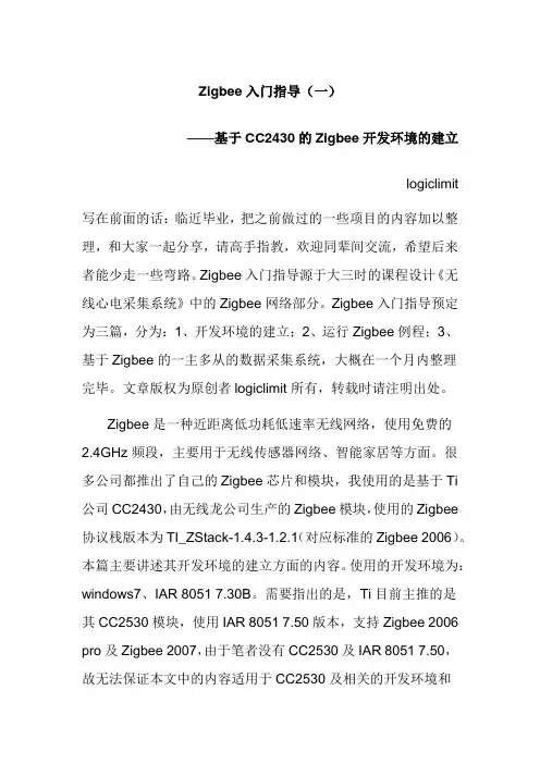
Zigbee入门指导(一)——基于CC2430的Zigbee开发环境的建立logiclimit 写在前面的话:临近毕业,把之前做过的一些项目的内容加以整理,和大家一起分享,请高手指教,欢迎同辈间交流,希望后来者能少走一些弯路。
Zigbee入门指导源于大三时的课程设计《无线心电采集系统》中的Zigbee网络部分。
Zigbee入门指导预定为三篇,分为:1、开发环境的建立;2、运行Zigbee例程;3、基于Zigbee的一主多从的数据采集系统,大概在一个月内整理完毕。
文章版权为原创者logiclimit所有,转载时请注明出处。
Zigbee是一种近距离低功耗低速率无线网络,使用免费的2.4GHz频段,主要用于无线传感器网络、智能家居等方面。
很多公司都推出了自己的Zigbee芯片和模块,我使用的是基于Ti 公司CC2430,由无线龙公司生产的Zigbee模块,使用的Zigbee 协议栈版本为TI_ZStack-1.4.3-1.2.1(对应标准的Zigbee 2006)。
本篇主要讲述其开发环境的建立方面的内容。
使用的开发环境为:windows7、IAR 8051 7.30B。
需要指出的是,Ti目前主推的是其CC2530模块,使用IAR 8051 7.50版本,支持Zigbee 2006 pro及Zigbee 2007,由于笔者没有CC2530及IAR 8051 7.50,故无法保证本文中的内容适用于CC2530及相关的开发环境和协议栈。
之前开发时使用的操作系统是Win XP,故本文所说的内容同样适用于win XP系统。
本文已假定读者了解IAR软件和cc2430单片机功能的使用,具有一定的C语言基础和嵌入式开发经验。
由于之前只有一个学期时间,还要完成相关模拟采集电路的设计,故Zigbee部分只完成网络的建立、数据的收发及控制的内容,稍显粗鄙,请勿见笑。
一、安装IAR 8051 7.30B使用管理员权限运行安装程序EW8051-EV-730B.exe,根据提示输入相应的注册码,完成相关的安装。
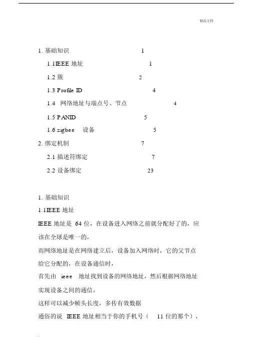
1. 基础知识 (1)1.1IEEE 地址 (1)1.2 簇 (2)1.3 Profile ID (4)1.4网络地址与端点号、节点 (4)1.5 PANID (5)1.6 zigbee设备 (5)2. 绑定机制 (7)2.1 描述符绑定 (7)2.2 设备绑定 (23)1.基础知识1.1IEEE 地址IEEE 地址是 64 位,在设备进入网络之前就分配好了的,应该在全球是唯一的,而网络地址是在网络建立后,设备加入网络时,它的父节点给它分配的,在设备通信时,首先由ieee地址找到设备的网络地址,然后根据网络地址实现设备之间的通信,这样可以减少帧头长度,多传有效数据通俗的说IEEE 地址相当于你的手机号(11 位的那个),短地址就相当于你们公司的小号(3 、4) 位,一个公司的互打电话就用小号噻。
假设你的手机号138xxxxx666 ,这个是唯一的,但你的小号,假设是 666,在你的公司网中是唯一的,但是在另一个网中,可能别人的小号也是666。
1.2 簇簇就是相当于端点房间里面的人,是接收最终的目标。
这东西是 2 个字节编号,在射频发送的时候,必须要指定接收模块的镞,发送模块不需要指定。
首先每一个端点可以看成是一个 1 个字节数字编号的开有一扇门的房间,数据最终的目标是进入到无线数据包指定的目标端点房间,而取无线数据这个相关的代码在任务事件处理函数里,TI 协议栈有那么多的任务事件处理函数,所以必须要指定在哪个任务事件处理函数来取这个无线数据包里面的有用数据。
端点就相当于一个房间的门牌号!!!SimonApp_epDesc.endPoint= 10;//SimonApp_ENDPOINT;此端点编号为10SimonApp_epDesc.task_id = &SimonApp_TaskID;和我们应用层任务挂钩完成了簇信息表的构建,因为簇信息封装在SimonApp_SimpleDesc 里面,这里面却只是起到一个信息表的作用!方便数据到来的时候查询相关信息表!const cId_t SimonApp_ClusterList[SimonApp_MAX_CLUSTERS] ={SimonApp_CLUSTERID};const SimpleDescriptionFormat_t SimonApp_SimpleDesc = {SimonApp_ENDPOINT,// int Endpoint;SimonApp_PROFID,//uint16 AppProfId[2];SimonApp_DEVICEID,//uint16 AppDeviceId[2];SimonApp_DEVICE_VERSION,//int AppDevVer:4;SimonApp_FLAGS,//int AppFlags:4;SimonApp_MAX_CLUSTERS,//byte AppNumInClusters;(cId_t*)SimonApp_ClusterList,//byte *pAppInClusterList;SimonApp_MAX_CLUSTERS,//byte AppNumInClusters;(cId_t*)SimonApp_ClusterList//byte *pAppInClusterList;};接收到数据以后,判断是属于哪一个端点、属于哪一个簇1.3 Profile ID这个是由Zigbee 组织来分配的应用ID 号,比如无线开关用0x0001 ,智能电表用ox0002,万用遥控器用0x0003 等等。
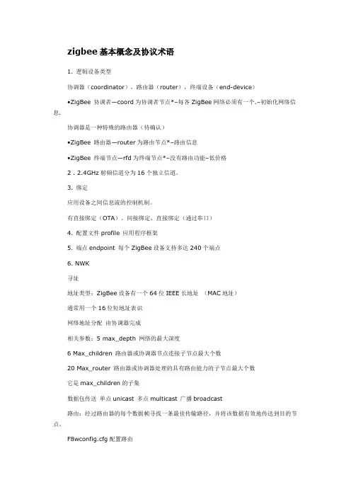
zigbee基本概念及协议术语1. 逻辑设备类型协调器(coordinator),路由器(router),终端设备(end-device)•ZigBee 协调者—coord为协调者节点*–每各ZigBee网络必须有一个.–初始化网络信息.协调器是一种特殊的路由器(待确认)•ZigBee 路由器—router为路由节点*–路由信息•ZigBee 终端节点—rfd为终端节点*–没有路由功能–低价格2 . 2.4GHz射频信道分为16个独立信道。
3. 绑定应用设备之间信息流的控制机制。
有直接绑定(OTA)、间接绑定、直接绑定(通过串口)4. 配置文件profile 应用程序框架5. 端点endpoint 每个ZigBee设备支持多达240个端点6. NWK寻址地址类型:ZigBee设备有一个64位IEEE长地址(MAC地址)通常用一个16位短地址表识网络地址分配由协调器完成相关参数:5 max_depth 网络的最大深度6 Max_children 路由器或协调器节点连接子节点最大个数20 Max_router 路由器或协调器处理的具有路由能力的子节点最大个数它是max_children的子集数据包传送单点unicast 多点multicast 广播broadcast路由:经过路由器的每个数据帧寻找一条最佳传输路径,并将该数据有效地传送到目的节点。
F8wconfig.cfg配置路由看了下面就不用纠结了。
配置文件(profile):Zigbee协议的配置文件是对逻辑组件及其相关接口的描述,是面向某个应用类别的公约、准则.通常没有程序代码与配置文件相关联.属性(attribute):设备之间通信的每一种数据像开关的状态或温度计值等皆可称为属性.每个属性可得到唯一的ID值.簇(cluster):多个属性的汇集形成了簇,每个簇也拥有一个唯一的ID.虽然个体之间传输的通常是属性信息,但所谓的逻辑组件的接口指的却是簇一级的操作,而非属性一级.终端(endpoint):每个支持一个或多个簇的代码功能块称为终端.不同的设备通过它们的终端及所支持的簇来进行通信.Cluster: is a container for one or more attributes. (一个或更多属性的集合)Attribute: a data entity which represents a physical quantity or state.(反映物理特性或状态的一个数据实体)Cluster是逻辑设备之间的事务关系Cluster定性Attribute则是某种事务关系的具体特例Attribute定量Endpoint是一个逻辑设备(个人理解为入口地址)。
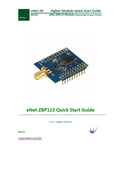
eNet-ZB ZigBee Module Quick Start GuideBestU eNet-ZBP113 Module-Networking Firmware VersioneNet-ZBP113 Quick Start GuideV1.0 – August 16,2014BestU/enZigBee Wireless sensor network moduleCopyright Statement:●Unless otherwise noted, the eNet-ZB Serials includes but not limit to eNet-ZBP113,eNet-ZBP111, eNet-ZBP211, eNet-ZBP213.●eNet、eNet-ZB Serials ZigBee wireless module and its related Intellectual Propertyowned by Shenzhen BestU Intelligent Technology Co.,Ltd.●Without the permission of Shenzhen BestU Intelligent Technology Co.,Ltd ,No one canmodify, distribute or copy any part of this document.Legal Disclaimer:●The source code, software, documents in company with eDuino UNO, Shenzhen BestUIntelligent Technology Co.,Ltd does not provide any guarantee; Not matter specific,connotative , including but not limited to specific purpose, all the risk should beundertook by end user; If coming out bug in the program, end user undertakes the allthe necessary fee of service, modification, amends.Version Updated:Version Updated Date Description1.0 2014-08-16 ReleasedZigBee Wireless sensor network moduleCatalogue1Overview (3)2Development Kit s (4)2.1 eDuino UNO Wireless Kit (4)2.2 Simple Wireless Kit (5)3Preparation (6)3.1 CP2102 driver Installation (6)3.2 Configuration Software Installation (7)3.3 Hardware Installation (8)3.3.1 eDuino UNO Wireless Kit (8)3.3.2 Simple Wireless Kit (10)3.3.1 Parameter Configuration (12)4Network Establishing (18)4.1 Coordinator settings (18)4.2 Router settings (19)4.3 Joining Network (20)4.4 Network Communication Test (21)5Contact Us (22)ZigBee Wireless sensor network module1OverviewThis document gives a description on how to get started with the eNet-ZBP113 development kits. This document provides a step by step guide to the installation procedure of the software and the hardware.If you buy only the eNet-ZBP113 module, the eNet-ZBP113 User Manual will be helpful when you get started with the module.Chapter 5 shows how to configure the module. Chapter 6 shows how to implement the data transmission between modules. Chapter 7 shows how to establish a network.ZigBee Wireless sensor network module2 Development Kit sThere are two available development kits for eNet-ZBP113, eDuino UNO wireless kit and Simple Wireless kit.2.1 eDuino UNO Wireless KiteNet-ZBP113 ModuleeDuino UNOeDuino UNO kitWhat ’s included in the eDuino UNO kit:Figure 2-1 eDuino UNO KitZigBee Wireless sensor network module2.2 Simple Wireless KiteNet-Test-AeNet-ZBP113 Module Simple Wireless kitWhat’s included in the Simple Wireless kit:Figure 2-2 Simple Wireless KitZigBee Wireless sensor network module3Preparation3.1CP2102 driver InstallationThe first time you connect the development kits to PC, the CP2102 driver need to be installed. Please download the driver from/Support%20Documents/Software/CP210x_VCP_Windows.zipZigBee Wireless sensor network module3.2Configuration Software InstallationBefore you install the configuration software for eNet-ZBP113, you first need to install the Microsoft .Net Framework if your PC has never installed one. The version, v4.0.30319 or later version is OK. Microsoft .Net Framework 4.5 can be downloaded from/en-us/download/details.aspx?id=30653Please download the configuration software from/uploads/soft/Document/ZigBee%20Module%20Config%20Tool.rarZigBee Wireless sensor network module3.3 Hardware Installation 3.3.1eDuino UNO Wireless Kit1) Install the antenna.2) Connect the eNet-ZBP113 module.Caution: Please take care to connect the module in the right way! See the next picture for more information.3) In order to make the USB-UART connect to eNet-ZBP113 module, jumpers should be fittedas follow figure shown.Figure 3-1 eNet-ZBP113 ModuleFigure 3-2 eDuino UNO KitZigBee Wireless sensor network module4)Plug Micro USB cable into PC and power the board.5)Check the available interface (COM) in Device Manager Window.Figure 3-3 Available Interface (COM)6)The kits start to work.Figure 3-4 eDuino UNO KitZigBee Wireless sensor network module3.3.2Simple Wireless Kit1)Install the antenna.Figure 3-5 eNet-ZBP113 Module2)Connect the eNet-ZBP113 module.Caution: Please take care to connect the module in the right way! See the next picture for more information.Figure 3-6 Simple Wireless Kit3)Connect the kit to PC with Micro USB cable and power the board.4)Check the available interface (COM) in Device Manager window.ZigBee Wireless sensor network moduleFigure 3-7 Available Interface (COM)7)The kits start to work.Figure 3-8 Simple Wireless KitZigBee Wireless sensor network module3.3.1Parameter ConfigurationThis section shows how to quickly configure module parameters with ZigBee Config Tool, a convenience, easy-to-use PC Software.1)Connect the module to PC through USB-UART.Figure 3-9 Connect the ModuleZigBee Wireless sensor network module2)Get the parameters from the Module.Click on the Get Para to get the current parameters of the module.Figure 3-10 Get the parametersZigBee Wireless sensor network module3)Set the network parameters.Set the PANID or change the Point type. Click on Setting button to finish the setting.Figure 3-11 Set the network parametersZigBee Wireless sensor network module4)Set the Radio parameters.Set the channel or TX Power and click on Setting to finish the setting.Figure 3-12 Set the Radio parametersZigBee Wireless sensor network module5)Set the UART parameters.Set the Baud Rate and click the Setting to finish the Setting.Figure 3-13 Set the UART parametersZigBee Wireless sensor network module6)Restart the module.Click the Restart to make the module work with the parameters set by steps before.Figure 3-14 Restart module7)Connect the module. The parameters have been set and shown by click Get Para.ZigBee Wireless sensor network module4Network EstablishingeNet-ZBP113 can act as Coordinator and Router. A ZigBee Network contain one Coordinator and one or more Router. All the nodes in a same network share the same PANID. The default settings of eNet-ZBP113 shown in Appendix I Default Settings of eNet-ZBP113 User Manual.Please note that more than one eNet-ZBP113 need for establish network.4.1Coordinator settingsHere is an example that shows how to configure a module as a Coordinator.Figure 4-1 Coordinator SettingsZigBee Wireless sensor network module4.2Router settingsHere is an example that shows how to configure a module as a Router.Figure 4-2 Router SettingsZigBee Wireless sensor network module4.3Joining NetworkPower the Coordinator before the Router. P0_6 of both modules will output a 1Hz pulse to indicate network establishing complete. Check the Short Add of the Router by click on Get para button. If the Short Add isn’t 0xFFFE, the Router has joined the network.Figure 4-3 Router have joined the networkZigBee Wireless sensor network module4.4Network Communication TestWhen the network is available, data can transfer between the Coordinator and Router.Open HyperTerminal on PC. S end strings “hello Router” from Coordinator and the Router received the strings. Both the Coordinator and Router can send or receive data.Figure 4-4 Network Communication TestZigBee Wireless sensor network module5Contact UsTechnical SupportTel:+86-755-22360817/130****2937Email: ******************Sale SupportTel: +86-755-22360817Email: ****************/130****2937About BestUHi, we are BestU, we believe that you will be more happy and better with our products and services.Our technology focused on IoT and open hardware.We own the“Brain”, the microcontroller module for Industry Area, like a brain to manipulate the various branches.We own the “Brick”, providing base IOT modules like WIFI/ZigBee/NFC/BLE etc. to bring down your development threshold, to quickly build your product prototypeWe own the “Low Kit”, providing the lowest hardware for you to evaluate and build your product. Better because of your good, we hope the products and services we have can make you be more excellent!More info please visit /en。
E18 系列ZigBee模块快速操作方法1. E18系列ZigBee模块简介E18 系列模块是成都亿佰特电子科技有限公司设计生产的一款2.4G ZigBee无线模块。
采用美国德州仪器(TI)公司原装进口的CC2530F256射频芯片。
E18 模块根据型号不同,可分为4.5dBm和20dBm最大功率输出。
内置组网固件,其固件采用TI 经典ZigBee协议栈Z-stack2.5.1a,支持串口数据传输。
该组网固件支持低功耗,角色切换,广播、组播、点播等多种功能。
并支持串口指令操作。
可轻松对模块进行配置和使用。
2. 快速入门•ZigBee自组网模块具有简单易用的特点。
通信模式分为模式1(透传模式),模式2(半透传模式),模式3(协议模式)。
在模式1、2 下还可指定输出为短地址,MAC地址,RSSI等信息。
为了让用户能快速熟悉模块,本此实验将引导用户经过简单的配置实现各种模式下的配置和通信,工作模式为模式3(协议模式),波特率为默认波特率115200。
用户可将P1.6引脚拉低,进行HEX指令设置,为方便上位机观察,本次实验用HEX指令格式,AT指令用户不在本次试验中测试。
(AT指令模式下不能用于上位机配置。
)另外,用户可以不使用底板而使用外部微控制器(MCU)直接连模块UART进行串口指令通信,实现二次开发。
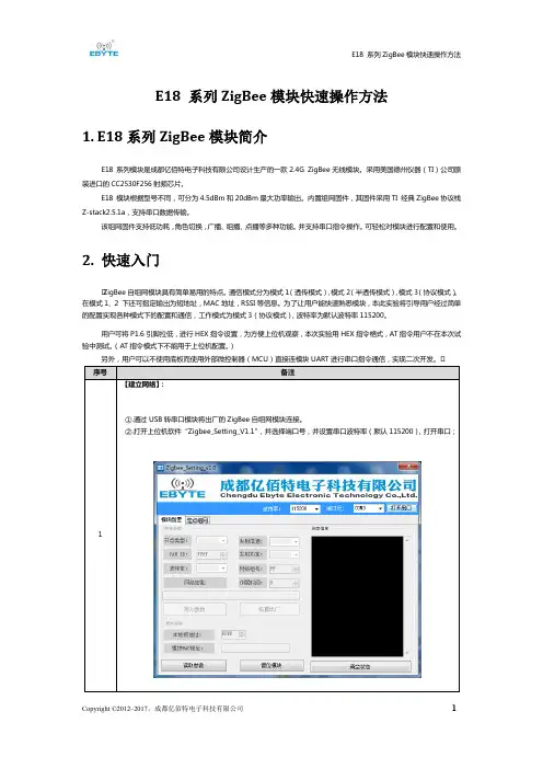
•备注【建立网络】:①.通过USB转串口模块将出厂的ZigBee自组网模块连接。
②.打开上位机软件“Zigbee_Setting_V1.1”,并选择端口号,并设置串口波特率(默认115200),打开串口;③.点击读取参数,读取相应模块参数。
④.选择节点类型为协调器,并写入参数。
等待协调器开始组建网络,用户可查看模块参数。
配置网络参数:(PAN ID为FFFF时为自动PAN ID)网络组建好读取参数:⑤.选择另一个模块,按照相同步骤设置为路由器或者终端(模块出厂默认为终端,可不进行设置,本实验为终端)。
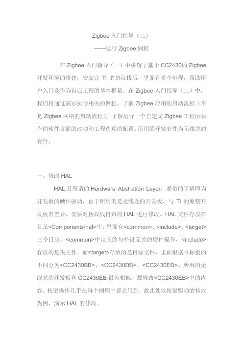
Zigbee入门指导(二)——运行Zigbee例程在Zigbee入门指导(一)中讲解了基于CC2430的Zigbee 开发环境的搭建,安装完Ti的协议栈后,里面有多个例程,帮助用户入门及作为自己工程的基本框架。
在Zigbee入门指导(二)中,我们将通过演示执行相关的例程,了解Zigbee应用的启动流程(不是Zigbee网络的启动流程),了解运行一个自定义Zigbee工程所要作的软件方面的改动和工程选项的配置。
所用的开发套件为无线龙的套件。
一、修改HALHAL及所谓的Hardware Abstration Layer,通俗的了解即为开发板的硬件驱动,由于所用的是无线龙的开发板,与Ti的原装开发板有差异,需要对协议栈自带的HAL进行修改。
HAL文件存放在目录<Components/hal>中,里面有<common>、<include>、<target>三个目录,<common>中定义的与外设无关的硬件操作,<include>存放的是头文件,而<target>存放的是目标文件,里面根据目标板的不同分为<CC2430BB>、<CC2430DB>、<CC2430EB>。
所用的无线龙的开发板和CC2430EB最为相似,故修改<CC2430EB>中的内容。
按键操作几乎在每个例程中都会用到,故此处以按键驱动的修改为例,演示HAL的修改。
先了解下Ti和无线龙扩展板的不同之处。
Ti的CC2430EB 原理图在Ti文档SWRU133.pdf(位于SWRU133.zip中)。
Page29是按键电路的原理图,如图1图1(左上角是元件图)CC2430EB的按键其实是摇杆,上下左右四个方向和电阻网络相连,通过放大电路送到CC2430的P0.6脚,经AD采样后判断摇杆摆向哪个方向,按键编号为SW1~SW4摇杆也可像普通按键一样按下,产生一个直流电平变化,接到P0.5脚,按键编号为SW5。

ZigBee技术入门2013/12/311ZigBee技术介绍•ZigBee无线网络协议是基于标准的七层开放式系统互联(OSI)模型,但仅对那些涉及ZigBee的层予以定义。
IEEE802.15.4标准定义了最下面的两层:物理层(PHY)和介质接入控制子层(MAC)。
ZigBee联盟提供了网络层和应用层(APL)框架的设计。
其中应用层的框架包括了应用支持子层(APS)、ZigBee设备对象(ZDO)和由制造商制订的应用对象。
2013/12/312ZigBee节点类型•节点类型•ZigBee 协调者(ZC)–每各ZigBee网络必须有一个.–初始化网络信息.•ZigBee 路由器(ZR)–路由信息•ZigBee 终端节点(ZED)–没有路由功能–低价格2013/12/3132013/12/314ZigBee 具有多种网络拓扑最重要的是网状网络(Mesh)ZigBee CoordinatorZigBee Router ZigBee End DeviceStar 星Mesh 网Cluster Tree 串2013/12/315CC2430/CC2431介绍ZigBee技术特点•低功耗;•低成本;•低速率;•近距离;•短时延;•高容量;•高安全;•免执照频段。
2013/12/316C51RF-3-PK配置序号名称单位数量备注1C51RF-3仿真器台12ZigBee高频模块块3CC24303USB线根24网络扩展板块2液晶5短接帽个66电池底板个37光盘张18天线支3杆状2.4G9保修卡张12013/12/318网络表演板•尺寸:–111.58㎜×82.28㎜×26.50㎜•电源电压:–5V(DC)•液晶:–128×64,点阵图形液晶•按键:–6个用户按键,1个复位按键•传感器:–光敏、电位器•接口:–RS232接口,10针JTAG插,无线龙无线模块标准插座,USB转串口等2013/12/31102013/12/3112ZigBee 模块•尺寸:–33.02×㎜26.80㎜×18.00㎜•工作电压:2.0V-3.6V•工作频率:2400M-2483.5M •芯片闪存:128K •芯片RAM :8K•接收灵敏度:-101dB •最大发射功率:0dBm •传输速率:≦250K •休眠功耗:约2uA•发射接收功耗:约30mA电池底板•尺寸:62.40㎜×30.54㎜×19.10㎜•电池电压:1.5V×2•接口:无线龙模块接口,10针插座,JTAG接口。
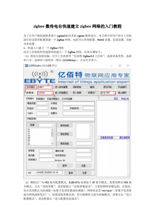
zigbee数传电台快速建立zigbee网络的入门教程
为了让用户能快速熟悉基于zigbee3.0技术的zigbee数传电台,本文将引导用户结合上位机进行经过简单配置搭建一个ZigBee网络,包括节点类型配置、PANID设置、信道设置、发射功率设置。
1、快速入门建立一个ZigBee网络
结合上位机软件快速简单的建立一个ZigBee网络,具体步骤如下:
(1)将电台连接电脑,打开上位机软件“亿佰特ZigBee3.0上位机”,选择设备类型,选择串口号,选择串口波特率(默认115200kbps),点击打开串口。
(2)模组出厂为HEX指令配置模式,E180-DTU如果处于AT指令模式,需要切换至HEX指令模式,点击“读取参数”,消息框提示“读取参数成功”,主要的网络参数包括:长地址,电台类型默认为协调器(如果不是请设置成协调器),网络状态是"not have"(如果不是需要退出网络或恢复出厂)。
如果读取参数无效,有可能模组当前为传输模式,需要点击“进入配置模式”,消息框提示“进入配置状态成功”。
(3)点击“开始配网”,协调建立一个开放网络,协调器新建网络后会持续180秒开放网络,LINK灯1Hz闪烁,路由器和终端可以在这个时间内加入网络。
zigbee学习之--入门一、基础定义及知识。
1、何为ZigBee,与普通的RF技术有何区别?ZigBee是一种具有低成本低复杂度低功耗的小范围低速率的无线传输技术。
相对于普通的RF技术,其重要的特点是;(1) 低功耗,速率低数据量少。
、(2)自组织网络,可适应网络拓扑结构动态变化。
(3)高可扩充,在有协调器加入的情况下,最高可达65535个ZigBee节点。
2、何为IEEE 802.15.4,其特点。
是ZigBee无限传感器网络通信标准,具有短距离(10m),低功耗,低速率,低成本的特点,支持单跳星形(10m内)和多跳对等(>10m)两种网络拓扑。
3、何为Z-Stack?Z-Stack是TI公司开发的ZigBee协议栈,并且经过了ZigBee联盟的认可而为全球众多开发商所广泛采用。
Z-Stack实际上是帮助程序员方便开发ZigBee的一套系统,它采用轮转查询式操作系统,包括两个主要流程(如图):系统初始化和执行操作系统。
系统初始化完成后,就进入执行操作系统,并且在其中是一个死循环。
执行操作系统中主函数即为轮询式操作系统的主体部分,也是我们需要重点开发、调用、掌握的部分。
欲知其详,且听下文分解。
有关第一部分的题外话,笔者在学习的时候,还是详细看了ZigBee概述和IEEE 802.15.4通信标准的,不过事后发现,如果只是想达到能调用Z-Stack中的函数进行简单的程序编写,尤其像我们这样为了比赛而准备的短期突击学习来说,并没有太大必要去详细了解这些标准,不过看了这些标准之后,的确会对后面的学习有些帮助。
另,为了能看懂一些Z-Stack资料,需要知道很多的名词定义和缩写,这部分我就放在了第四章,如果有看不懂的地方,可以先跳到第四章查询。
二、开发Z-Stack须知。
1、ZigBee的体系,数据及管理的方式和方向。
ZigBee网络构架。
上图是ZigBee协议的体系结构。
上图是zigbee网络构架。
学习ZigBee入门申明:学习zigbee入门,参考了零基础学zigbee文档资料等。
Zstack 情况:采用TI 的Zstack1.4.3 协议,IAR7.30B版本第一步:安装Zstack从TI 官方网站上下载的Zstack 为:swrc072c.zip,我想这个压缩包大家都认识。
解压之后为:ZStack- CC2430-1.4.3.exe 文件。
这个安装文件大家都会了。
默认安装路径为:C:\Texas Instruments\ZStack-1.4.3。
安装之后在C:\Texas Instruments\ZStack-1.4.3 目录下有各PDF 文档为:Getting Started GuideCC2430.pdf,不用多说,这个肯定是要看的。
既然把它放到这么前面,说明它是入门中的入门文档。
下面就简单介绍下这个文档(注意哦,结合了我的开发套件):1、介绍了安装ZStack-CC2430-1.4.3.exe 需要的硬件软件条件:需要电脑、操作系统为Windows 2000 或Windows XP。
至于更高或更低版本的本人没有尝试。
2、讲了安装流程。
这个有点多余了,这年月哪个有电脑的没有安装上百上千次的软件啊?但是需要强调的是安装路径----默认就好!3、接下来就是让我们看的第一个文档为:Start->Programs->Texas Instruments->ZStack-1.4.3->Z-Stack User’s Guide,第二步:Z-Stack 用户指导这个文档的更新时间为:2007 年12 月21 日----应该还是比较新的版本。
由于本人英文的却有限,就不翻译了,浏览一遍,把大概意思说下就可以了:1、介绍1.1、适用范围本文档适用于CC2430开发板(具体的板子不同也会有差别)2、产品包描述2.1、安装包内容这个就是上面提到的的ZStack-CC2430-1.4.3.exe 安装之后的所有内容了。
Zigbee入门开发Zigbee是一种新型的短距离无线通信技术。
其特点是低功耗,低成本,组网灵活。
Zigbee协议由zigbee 联盟指定,包括应用层,和网络层,其下层采用IEEE802.15.4协议。
无论是学习zigbee技术,还是利用zigbee技术开发产品,都需要较好的掌握zigbee协议,并比较深入的了解IEEE802.15.4协议.然而仅zigbee协议就接近400页,而IEEE802.15.4协议多达600页,全部是英文。
如果从来没有接触过无线通信的开发,要迅速掌握这么多内容确实有一些难度,笔者考虑到广大急切进入zigbee的同仁者,结合自己开发中总结出的理解协议的特定方法,从开发的角度,阐述协议内容,以达到抛砖引玉的效果,同时和广大同仁交流,共同提高,并希望zigbee技术能够在中国发扬光大。
协议从功能实现来讲,ZigBee协议层共包括物理层(又称实体层)、MAC层、数据链接层、网络层和应用支持层五个主要层次。
在标准制定的分工上,ZigBee协议层是由ZigBee联盟和IEEE802.15.4的任务小组共同完成的。
其中,物理层(又称实体层)、MAC层、数据链接层,以及传输过程中的资料加密机制等都是由IEEE所主导的。
网络层和应用支持层则由ZigBee联盟来完成。
IEEE802.15.4小组与ZigBee联盟共同针对ZigBee协议栈的发展进行研究,而未来还能依据系统客户的要求来修正其所需的应用界面。
如图1所示:Zigbee协议整体架构作为理解协议,从开发者的角度来讲,这样学习协议是比较费时间的,也较难掌握。
笔者从自己长期开发的经验来看,对无线通信,最重要的就是在发送端根据用户的要求,把数据能够扔出去,并且是扔到指定的设备,在接收端,能够把发送到该设备的数据捡起来。
并根据用户要求的作特定的处理。
如果考虑在一个无线网路中的话,就得首先建立网络,其他得设备加入网络。
最后是才是一些其他的问题,如设备离开网络,设备重新加入网络,等等。
ZigBee基础知识讲解目录一、ZigBee技术概述 (2)二、ZigBee网络结构 (3)2.1 网络拓扑结构 (4)2.2 设备角色 (5)2.3 基本网络模式 (6)三、ZigBee协议栈 (7)3.1 物理层 (8)3.2 链路层 (10)3.3 网络层 (11)3.4 应用层 (12)四、ZigBee设备类型 (13)4.1 网络协调器 (14)4.2 节点设备 (15)4.3 外部设备 (17)五、ZigBee通信机制 (18)5.1 数据传输方式 (19)5.2 通信协议 (21)5.3 数据传输速率与容量 (22)六、ZigBee安全机制 (23)6.1 认证机制 (25)6.2 隐私保护 (26)6.3 安全服务与应用 (27)七、ZigBee设备配置与调试 (29)7.1 设备初始化 (30)7.2 网络参数设置 (32)7.3 设备状态监控与维护 (33)八、ZigBee应用案例分析 (35)8.1 智能家居系统 (36)8.2 工业自动化控制系统 (38)8.3 智能交通系统 (39)8.4 公共安全监测系统 (41)九、ZigBee发展趋势与挑战 (42)9.1 技术发展趋势 (44)9.2 应用前景展望 (45)9.3 面临的挑战与应对策略 (47)一、ZigBee技术概述定义与特点:ZigBee是基于IEEE 标准的无线通信技术,具有低功耗、低数据速率、低成本和可靠性的特点。
ZigBee联盟通过扩展IEEE标准,增加了网络、安全和应用层的功能。
该技术主要适用于需要长时间工作且电池寿命非常关键的应用。
应用领域:ZigBee技术广泛应用于智能家居、工业自动化、智能农业、智能交通等领域。
智能家居中的照明控制、安防系统。
网络结构:ZigBee网络主要由协调器(Coordinator)、路由器(Router)和终端设备(End Device)组成。
协调器负责创建和加入网络,路由器负责路由和数据转发,终端设备则执行特定的任务。