ASTM F609–05 使用侧向牵引滑动计(HPS)的试验方法
- 格式:pdf
- 大小:74.21 KB
- 文档页数:3


商用车辆前牵引装置试验方法
商用车辆前牵引装置的试验方法主要包括以下步骤:
1. 试验条件:
在车辆上进行,车辆应刚性地固定在试验场地上。
在车身或底盘上进行,车身或底盘应被固定牢固。
2. 试验载荷:
牵引装置能承受的最小载荷F为:对于货车和半挂牵引车,F=最大允许总质量×g/2;对于客车,F=整车整备质量×g/2。
其中,F表示牵引装置能够承受的最小静载荷,单位为牛(N);g表示重力加速度,/s²。
3. 性能要求:
试验完成后,试验样件应满足如下要求:牵引装置不应有影响正常工作的变形;安装在牵引装置附近的设备不应损坏或出现异常妨碍正常工作。
4. 安全性检查:
检查牵引连接部位的强度和防脱性,包括牵引架与车体的连接或焊接部分是否有裂纹、牵引销是否有明显的变形和过度的磨损、牵引防脱机构工作是否正常有效等。
检查的方法为目测。
当发现有异常时,可采用负荷加载法进行一步测试,确认其安全性。
此外,在进行商用车辆前牵引装置试验时,应严格遵守相关法律法规和标准,确保试验过程的安全性和准确性。
同时,建议在进行试验前制定详细的试验计划和方案,以确保试验结果的可靠性和准确性。

推拉力计操作规程一、引言推拉力计是一种用于测量物体的推力和拉力的仪器。
本操作规程旨在指导使用者正确操作推拉力计,确保测量结果的准确性和安全性。
二、设备准备1. 确保推拉力计处于正常工作状态,检查仪器外观是否完好无损。
2. 检查推拉力计的电源是否充足,如需更换电池,请使用符合规定的电池。
3. 准备合适的测量夹具或者固定装置,确保能够稳定地固定待测物体。
三、操作步骤1. 将推拉力计固定在测量夹具或者固定装置上,确保推拉力计与待测物体之间没有干扰物。
2. 打开推拉力计的电源开关,待仪器启动完成后,进行零位校准。
3. 按照待测物体的特性选择合适的测量模式,如推力模式或者拉力模式。
4. 将待测物体与推拉力计连接,确保连接坚固,避免浮现松动或者脱落。
5. 缓慢施加推力或者拉力,直到推拉力计显示稳定的测量结果。
6. 记录测量结果,并根据需要进行单位转换或者计算。
四、注意事项1. 在操作推拉力计时,应穿戴符合要求的个人防护装备,如手套和护目镜,以确保安全。
2. 避免将推拉力计暴露在高温、潮湿或者腐蚀性环境中,以免损坏仪器。
3. 在操作过程中,应注意待测物体的稳定性,避免浮现滑动或者摇晃的情况,以确保测量结果的准确性。
4. 如需进行多次测量,应等待推拉力计恢复到初始状态后再进行下一次测量。
5. 定期对推拉力计进行校准和维护,以确保仪器的精度和可靠性。
五、故障排除1. 若推拉力计显示异常或者无法正常工作,请检查电源是否正常连接,电池是否需要更换。
2. 如仍无法解决问题,请联系售后服务人员进行维修或者更换。
六、安全提示1. 在使用推拉力计时,应遵循相关的安全操作规定,确保操作人员的人身安全。
2. 如发现任何异常情况或者操作不当可能导致危(wei)险的情况,应即将住手使用,并采取相应的安全措施。
七、附录1. 推拉力计的技术规格和性能参数。
2. 推拉力计的维护保养方法和周期。
以上为推拉力计操作规程的详细内容,希翼能够对您的工作有所匡助。
涂层附着力试验的方法及判定涂层的附着力包括两个方面:有机涂层与底材金属表面的附着力(adhesion);有机涂层本身的内聚力(cohesion)有机涂层与金属表面的附着力强度越大越好;涂层本身坚韧致密的漆膜两者共同作用才能更好的阻挡外界腐蚀因子对金属的腐蚀,从而达到对金属的良好的保护。
涂层不能牢固的附着于金属表面,再完好的涂层也起不到作用(adhesion failure);涂层本身内聚力差,漆膜容易开裂(checking、cracking)而失去作用。
以上两者共同决定涂层的附着力,构成决定涂层保护作用的关键因素。
涂层附着力的检测:现场检测实验室检测现场检测:用刀具划X(ASTM D3359Method A X-cut tape test)或划格法(ASTM D3359 Method B Cross-cut tape test)以及拉开法(ISO 4624 Pull off test for adhesion);实验室检测:划圈法(GB 1720)适用范围:划X法用于干膜厚度高于125μm 的情况下;划格法适用于干膜厚度在250μm的情况。
1.划X法(X-cut tape test)测试程序使用工具:美工刀、半透明压敏胶袋:○1涂层表面要求清洁干燥,高温和高湿会影响胶带的附着力;○2用美工刀沿直线稳定的切割涂膜至底材,夹角为30°~45°,划线长度约40mm,交叉点在划线的中间,确保划线至金属底材;○3把胶带放在切割线交点处,用手抹平(胶带的颜色可以帮助判断与漆膜的接触密实程度);○4将胶带以180°从漆膜表面撕开,观察涂层拉开后的状态a.5A 没有脱落;b.4A 沿刀痕有脱落的痕迹;c.3A 刀痕两边都有缺口状脱落达1.6mm;d.2A 刀痕两边都有缺口状脱落达3.2mm;e.1A 胶带下X区域内大片脱落;f.脱落面积超过X区域。
示意图如下:其中 5A—3A为附着力可接受状态。
试验与检测商品与质量 2014年第7期225水龙头金属材料对饮用水水质的影响王春通标标准技术服务(上海)有限公司 上海 201319摘要:制造厨房水龙头的金属材料在长时间的水浸泡中,不断析出离子而严重影响水质。
本文对水龙头重金属析出指标和水龙头制造原材料中重金属质量百分比等进行了阐述,并通过实验指出:水龙头金属材质影响了自来水的水质,前3~5L 的过夜水头水不宜饮用。
建议使用优质安全的生活饮用水水龙头。
关键词:水龙头 重金属 水质 标准0.前言家庭厨房中的水龙头是卫浴供水件主要产品之一,经水龙头流出的水,不是被人加热饮用,就是烧饭菜、刷牙及洗涤蔬菜、瓜果、衣服,与人们的日常生活密切相关。
随着人们对身体健康和食品安全的日益关注,水龙头中重金属离子在水中的析出及析出指标,成为百姓及行业关心的重要环境健康安全指标。
1.水龙头重金属析出⑴.重金属离子的析出。
水龙头是由金属、陶瓷和塑料等材料组成,金属中锌、铜等重金属含量不少,加工中加入的少量铅被偏析在水龙头的内外表面。
水龙头中的水会破坏洗铅的表面,形成“腐蚀”,内部的铅离子被暴露出来,导致一定程度的铅析出溶到水中,尤其是水管中滞留的“隔夜水”,重金属含量更高。
⑵.重金属离子析出指标。
是指在排除重金属及其他有害成分干扰条件下,用近于真实自来水成分配制的浸泡水,按标准规定的浸泡程序及方法使用浸泡水,对水龙头内和水接触的表面进行浸泡。
最后测试浸泡水中重金属析出的情况。
重金属析出指标与水龙头制造原材料中的质量百分比有极大的相关性,通常情况下,重金属质量百分比的高低会决定其析出指标的高低。
⑶.重金属析出相关标准①.基础标准。
GB 5749-2006《生活饮用水标准》,为全文强制性国家标准,其内容包括我国生活饮用水水质卫生要求和涉及生活饮用水卫生安全产品的卫生要求。
②.方法标准。
主要有:GB/T17219-1998《生活饮用水输配水设备及防护材料的安全性评价标准》,JC/T1043-2007《水嘴铅析出限量》,HJ/T411-2007《环境标志产品技术要求水嘴》等。
在实验室摇摆条件下选择不同类型、黏度的基础油、润滑油、柴油等样品,考察了 SVM3000型斯塔宾格黏度i卜的重复性、再现性,并4常规条件下品氏黏度计的测试结果进行了对比。
结果表明,斯塔货格黏度计在摇摆条件下的测定结果具打良好的重复性和再现性,满足GJB 9131精密度要求,3品氏黏度计测定结果的符合性好,在船1丨!油料现场快速检测领域打较好的疢用前景。
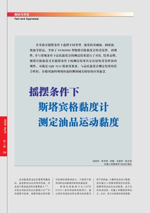
摇摆条件下斯塔宾格黏度计测定油品运动黏度尚培华宋开财宋敏王建华张文田中国人民解放军92228部队运动黏度是油品的重要质量指 标,直接影响油品的使用性能,对 其进行现场监控具有重要意义[1’2]。
目前应用较多的品氏黏度计法[3]对 环境要求较高,摇摆和振动等因素对检测结果影响较大,不能用于船用油料运动黏度的现场快速检测。
斯塔宾格黏度计法(ASTMD7042)是利用液体的黏滞力,通过测定恒速驱动样品管内轻质悬浮转子的转速,计算样品的动力黏度,进而通过U型震荡管测定的密度,换算得到油品的运动黏度。
该方法具有测试快、用量少和精度高等优点。
此外,该方法检测结果受摇摆、震动等环境因素较小;检测不同黏 度范围液体,无需更换黏度管;釆 用帕尔帖半导体控温技术控温,无需液体恒温浴,因此在船用油料运 动黏度检测方面具有较大的应用 前景。
目前,斯塔宾格黏度计法已在 国外得到广泛应用,美国已将其作 为黏度测定方法,写入到柴油(ASTM D975—14 )、航空涡轮燃料(ASTM D756—14 和 ASTM D1655—14) 等油品的标准中。
国内也有报道,该方法对基础油以及润滑油和燃料 油等成品油的检测结果与毛细管法 检测结果具有较好的相关性[4~6]。
笔者釆用重新起草法,修改釆 用ASTM D7042—14制定了国家军 用标准GJB 9131—2017《液体动 力黏度和祖度的测定及运动黏度的 计算斯塔宾格黏度计法》,对基础 油、润滑油、柴油、喷气燃料和生 物柴油的检测精密度进行了规定,为该方法在国内应用奠定了基础。
介质损耗测试仪技术指标北京恒奥德新款打折运动粘度测试仪原理运动粘度测试仪又称运动粘度测定仪,运动粘度测定器,全自动运动粘度测定仪是测量透亮或不透亮流体运动粘度的全自动化测试仪器,采纳MCS单片机掌控,恒温、测试、打印、粘度管清洗和烘干等过程实现全自动化。
仪器符合GB265—88标准。
广泛应用于石油、化工、油田、铁路、科研、计量等部门。
该仪器测试结果精度高,重复性和再生性好,操作简单便利。
原理本仪器是依据国家标准《GB/T265—88石油产品运动粘度测定法》设计制造的专用测试仪器,适用于测定液体石油产品的运动粘度。
仪器具有计时试样运动时间,自动计算运动粘度的结束果。
本方法适用于测定液体石油产品(指牛顿液体)的运动粘度,方法是在某一恒定温度下,测定肯定体积的液体在重力流过一个标定好的玻璃毛细管粘度计的时间,粘度计的毛细管常数与流动时间的乘积,即为该温度下液体的运动粘度。
动力粘度可由测得的运动粘度乘以液体在当前温度的密度所得。
功能与特点液晶屏幕,汉字显示,清楚明白,操作简便;键盘设定粘度计常数、掌控温度值、微调温度值、试验次数等参数,仪器具有参数记忆功能;采纳进口传感器,数字PID控温技术,控温范围宽,控温精度高;不掉电日历时钟,开机自动显示当前时间;网络通讯,遥控、汇表可选功能;试验次数1—6次可调,便利您的试验;试验记录可保管,便利以后查看。
介质损耗测试仪技术指标介质损耗测试仪采纳变频电源技术,利用单片机和电子技术进行自动频率改换、模/数转换和数据运算,实现抗干扰本领强、测试速度快、精度高、操作简便的功能。
仪器采纳大屏幕液晶显示器,测试过程通过汉字菜单提示既直观又便于操作。
随着电力事业的快速进展,对电力系统运行牢靠性要求将越来越高,电气设备绝缘检测技术的进展更加得到重视。
高压电力设备介质损耗角正切tanδ的检测是保证电力系统安全运行,适时发觉事故隐患,提高供电牢靠性的紧要技术手段。
因此,讨论介质损耗角的正切tanδ的检测技术具有非常紧要的意义。
Designation:F609–05An American National Standard Standard Test Method forUsing a Horizontal Pull Slipmeter(HPS)1This standard is issued under thefixed designation F609;the number immediately following the designation indicates the year oforiginal adoption or,in the case of revision,the year of last revision.A number in parentheses indicates the year of last reapproval.Asuperscript epsilon(e)indicates an editorial change since the last revision or reapproval.1.Scope1.1This test method covers measurement of the slip index of footwear sole,heel,or related materials on dry walkway surfaces in the laboratory and in thefield.1.2The dimensional values used in the test method are given in units of inches,pounds,or degrees Fahrenheit. Alternative equivalent values are in parentheses and are for informational purposes only.1.3This standard does not purport to address all of the safety concerns,if any,associated with its use.It is the responsibility of the user of this standard to establish appro-priate safety and health practices and determine the applica-bility of regulatory limitations prior to use.2.Referenced Documents2.1ASTM Standards:2E691Practice for Conducting an Interlaboratory Study to Determine the Precision of a Test MethodF1646Terminology Relating to Safety and Traction for Footwear3.Terminology3.1For definitions of terms,refer to Terminology F1646.4.Significance and Use4.1The Horizontal Pull Slipmeter3is a laboratory andfield instrument designed to provide information about the slip index characteristics between walkway surfaces and a test foot material under dry conditions only.The HPS can not be used on wet surfaces.Slip index can be affected by surface rough-ness,presence of water,contaminants such as grease and other foreign materials,andfloor surface wear over time.Slip index, as determined by the HPS,most likely will not give useful information for evaluating liquid contaminated surfaces,and therefore,will not provide an effective assessment of a poten-tial slipping hazard on a walkway surface under these condi-tions.4.2The value reported by the Horizontal Pull Slipmeter is called the slip index.Slip index is ten times the static coefficient of friction.For example,a static coefficient of friction of0.4is displayed by a slip index of 4.0when measured by the Horizontal Pull Slipmeter.4.3The HPS can be used on inclined surfaces.No adjust-ment for slope is needed for measurements in the direction perpendicular to the slope and when averaging four measure-ments at one location taken according to step10.14.5.Apparatus45.1Horizontal Pull Slipmeter—See Fig.1.6.Reagents and Materials6.1Silicon carbide abrasive paper,No.400grit.6.2Camel hair brush or other non-static bristle material.7.Test Foot7.1The test foot shall be Trademark Neolite5Test Liner that measure0.5in.(12.7mm)in diameter and0.25in.(6.35mm) to0.2in.(5.08mm),but not less than0.2in.(5.08mm)in thickness.When testing actual shoe materials,Neolite5should be replaced with the desired test materials.7.2A set of three test feet of the same material are required for performance of the test.8.Calibration8.1Place the switch button,which is located just below the dial,in the center position.No switch is found on later model1This test method is under the jurisdiction of ASTM Committee F13on Pedestrian/Walkway Safety and Footwear and is the direct responsibility of Subcommittee F13.10on Traction.Current edition approved Dec.1,2005.Published December2005.Originally approved st previous edition approved in1996as F609–96e1.2For referenced ASTM standards,visit the ASTM website,,or contact ASTM Customer Service at service@.For Annual Book of ASTM Standards volume information,refer to the standard’s Document Summary page on the ASTM website.3The Horizontal Pull Slipmeter was developed by C.H.Irvine of Liberty Mutual Insurance Co.,Hopkinton,MA.4The sole source of supply of the apparatus known to the committee at this time is C.S.C Force Measurement Inc.,84Ramah Circle North,Agawam,MA01001.If you are aware of alternative suppliers,please provide this information to ASTM International Headquarters.Your comments will receive careful consideration at a meeting of the responsible technical committee,1which you may attend.Plans for the instrument may be obtained at a nominal cost from ASTM International Headquarters.Order ADJ12-606090-47.5Neolite is a registered trademark with Goodyear Tire and Rubber Company. The sole source of supply of the apparatus known to the committee at this time is Smithers Scientific Services,Inc.,425West Market Street,Akron,OH44303,with an average specific gravity of1.2760.02and an average Shore A hardness of 93–96.If you are aware of alternative suppliers,please provide this information to ASTM International Headquarters.Your comments will receive careful consider-ation at a meeting of the responsible technical committee,1which you may attend.Copyright©ASTM International,100Barr Harbor Drive,PO Box C700,West Conshohocken,PA19428-2959,United States.--` , , ` ` ` , , , , ` ` ` ` -` -` , , ` , , ` , ` , , ` ---Chatillon ter model gages have replaced the switch button with a peak hold mode feature.8.2Grasp the slipmeter and hold in vertical position.8.3Set the gage on zero by moving the rim on the gage.8.4Use a separate hook to suspend the slipmeter by the hook located on one end of the slipmeter.The slipmeter should hang freely.8.5The needle on the dial of the gage should be within calibration range as indicated on the dial.If it is not within the calibration range,the HPS should be sent to the manufacturer 4for calibration.9.Conditioning9.1For testing in laboratories,condition test feet for at least 18to 24h in atmosphere maintained at 7363.6°F (22.862°C)and 5065%relative humidity.9.2When testing feet in the field or on fixed floor surfaces,conditioning of test feet in accordance with 9.1may not be possible.The results obtained during the ruggedness test indicated that temperature could have a significant effect on the measured slip index when tested at 50°and 85°F.Interpolation has not been established to make proper adjustments for different temperature and humidity.However,it is recom-mended that the temperature and humidity be recorded,since these records could help explain potential inconsistencies.10.Procedure10.1Insert a set of three test feet in the slipmeter recesses.Test feet can be held in place using all purpose glue.10.2Mount the abrasive paper on a flat 3by 7-in.(76.2by 77.8-mm)piece of 0.5-in.(12.7-mm)plywood.10.3Sand the test feet with No.400abrasive paper.The sanding procedure should consist of five strokes of 5to 6in.in length,parallel to the friction measurement direction,followed by five strokes of 5to 6in.in length,perpendicular to the friction measurement direction.10.4Lightly brush the test feet using the non-static brush to remove loose surface particles.10.5Place the slipmeter on its feet on the test walkway surface.The hook end shall face the power unit.Be sure all three test feet rest on the level walkway surface and not on a grout joint or other uneven surface.10.6Place the slipmeter power unit on the walkway surface in front of the slipmeter.10.7Put the switch that permits retention of maximum slip index indication in the center position.For later model Chatil-lon DPP-5gages with no switch,ignore this step.10.8Set the slip index meter on zero by rotating the bezel until pointer meets zero on dial.For later model gages with no switch,use black knob on dial to set red needle on zero with black peak hold needle immediately to right.10.9Push the switch on top of the gage toward the hookless end of the slipmeter to record the maximum.For later model gages with no switch,ignore this step.10.10Connect the string of the power unit pulley to the hook of the slipmeter.The string should be parallel with the test surface and in line with the pulley on the power unit.Align the pulley on the power unit with the hook on the slipmeter.Be sure to keep the string alignment from the pulley straight (0to 5°)with the hook on the slip meter.The string length between the pulley and the hook of the slipmeter should not be too short,that is,no less than 4in.or no more than two loops around the pulley.10.11Hold down the power unit with one or both hands to prevent it from moving;then depress the switch.N OTE 1—Do not exceed 10min dwell time between placing the test feet in contact with the walkway surface and slip index measurement.This dwell time is the time needed from 10.5to and including 10.11.Slip index should be measured within 30min after sanding and brushing,detailed in 10.3and 10.11.N OTE 1—Total weight of slipmeter less power unit is 5.9560.07lb (2700634g).Speed of power unit is 3.560.5in./ter model Chatillon DPP-5gages do not have a switch.Peak hold feature is found in the gage dial.FIG.1Horizontal PullSlipmeter--`,,```,,,,````-`-`,,`,,`,`,,`---10.12Switch off the power unit when the slipmeter begins to move.10.13Record the peak slip index reading shown on the slip index gage (position of black needle).Record slip index readings in excess of 8as >8.10.14Repeat 10.5through 10.13for a total of four times for each location.Rotate the slipmeter 90°in the same direction (clockwise or counterclockwise)after each time.11.Report11.1The recording of the following items is recommended.11.1.1Client/customer.11.1.2Location/address.11.1.3Date and time of test(s).11.1.4Cite ASTM Test Method F 609was used.11.1.5Name of HPS slipmeter operator.11.1.6Address and telephone number of operator.11.1.7Brand,model,and serial number of HPS slipmeter used.11.1.8Test foot preparation protocol.11.1.9Specific floor location and orientation of HPS slip-meter where test was performed.11.1.10Type of test foot material.11.1.11Slope of surface tested.11.1.12Floor material and texture.Provide details of grout joints and floor texture for tile and brick floors,and so forth.11.1.13Floor Finish —Indicate type of finish (for example,wax,polish,or paint)applied,if any,and condition of the finish.11.1.14Floor Conditions —Indicate surface condition.11.1.15Indicate dry testing.11.1.16Temperature and relative humidity (if relevant).11.1.17Record each slip index reading,and record the average of four readings under dry conditions.11.1.18Provide any comments relative to testing.12.Precision and Bias 612.1Six laboratories participated in the precision and bias testing using Trademark Neolite 5Test Liner under dry condi-tions with six floor materials which represented typical floor materials used.There were 16determinations,four in each direction,for each floor material.The values displayed below are slip index that are ten times static friction coefficient.The values of Sr and SR are the standard deviations for the repeatability and reproducibility,respectively,determined in accordance with Practice E 691.The values of r and R specify the 95%repeatability and reproducibility limits,respectively,for each material.MaterialAverage Sr SR r R Glazed ceramic 9.33440.37810.9670 1.0585 2.7077OVCT8.79170.6597 1.1251 1.8472 3.1502Glazed porcelain 8.3396037530.7738 1.0507 2.1665Red quarry8.16670.28610.54160.8012 1.5164Unglazed porcelain A 8.14270.24000.52330.6721 1.4653Glazed ceramic rough A8.54690.28880.66920.80871.8738ARandom texture pattern12.2Bias —The bias for the HPS is yet to be determined.13.Keywords13.1shoe heel;shoe soling;slip index;static coefficient of frictionASTM International takes no position respecting the validity of any patent rights asserted in connection with any item mentioned in this ers of this standard are expressly advised that determination of the validity of any such patent rights,and the risk of infringement of such rights,are entirely their own responsibility.This standard is subject to revision at any time by the responsible technical committee and must be reviewed every five years and if not revised,either reapproved or withdrawn.Your comments are invited either for revision of this standard or for additional standards and should be addressed to ASTM International Headquarters.Your comments will receive careful consideration at a meeting of the responsible technical committee,which you may attend.If you feel that your comments have not received a fair hearing you should make your views known to the ASTM Committee on Standards,at the address shown below.This standard is copyrighted by ASTM International,100Barr Harbor Drive,PO Box C700,West Conshohocken,PA 19428-2959,United States.Individual reprints (single or multiple copies)of this standard may be obtained by contacting ASTM at the above address or at 610-832-9585(phone),610-832-9555(fax),or service@ (e-mail);or through the ASTM website ().6Supporting data are available from ASTM Headquarters.Request RRF-13:1001.--`,,```,,,,````-`-`,,`,,`,`,,`---。