chap0_AX4030E_前言
- 格式:pdf
- 大小:1.06 MB
- 文档页数:10


Data SheetTri radio 4x4:4 MU-MIMO 802.11ac Wave 2 access pointC-130-EGKey SpecificationsKey Features• Up to 800 Mbps for 2.4 GHz radio • Up to 1.733 Gbps for 5 GHz radio • 802.11ac Wave 2 support • 4x4 MU-MIMO with four spatialstreams per radio• Third 2x2 MIMO radio for dedicatedRF and WIPS scanning• Ten integrated omnidirectionalantennas• 20/40/80/80+80 MHz channel widthsupport• 2x Gigabit Ethernet port • Full operational capacity with802.3at PoE+• Wall and ceiling mounting supportUltimate Blend of High Performance and Full-Time SecurityThe Arista C-130-EG is an enterprise-grade 4x4 MU-MIMO tri-radio 802.11ac access point with dual concurrent 5 GHz and 2.4 GHz band radios supporting 802.11a/n/ac Wave 2, 802.11b/g/n, four spatial streams, and data rates of up to 1.733 Gbps and 800 Mbps, respectively. It is the only access point today that contains a third 2x2 MIMO 802.11ac radio for dedicated multi-function scanning.Why Choose the C-130-EG?The C-130-EG is the only access point that provides consistent, high performance access with automatic, over-the-air threat prevention. The C-130-EG removes the need to sacrifice application performance for high security, and is a must for all critical, high-density networks that expect a high volume of diverse clients with diverse needs. Common deployment scenarios include large schools, large remote offices, auditoriums, meeting rooms, and enterprise campuses. With its Wave 2 chipset, the C-130-EG takes advantage of the latest modulation and beamforming techniques that transform WiFi networks and offer the speeds and reliability once thought only possible over the wire. Best of all, the C-130-EG offers this best-in-class performance at a similar cost to competitive 802.11ac Wave 1 and Wave 2 access points.Arista Cloud Managed WiFiThe C-130-EG is an Arista Cloud-managed platform and leverages a purpose built cloud architecture to produce enterprise-grade wireless networks forevery application required, ensuring high reliability through an approach that is automated, scalable, secure and cost effective.What Really MattersThe future of WiFi requires intelligent, self-reliant access points that support high-performing, highly reliable networks without the need for antiquated controllers. This approach removes the complexity, instability and high costs associated with enterprise WiFi today.• 100% controller-free• Zero-touch deployment through automatic cloud activation and configuration• Cloud-defined operating modes for dedicated access, dedicated security or dual-mode • Support for up to eight distinct SSIDs per radio• Integrated firewall, traffic shaping, QoS and BYOD controls per SSID • Dynamic RF optimization through smart steering, band steering and optimal channel selection • Automated device access logging • Non-WiFi VLAN monitoring for extended rogue access point detection• Third party analytics integration for real-time data transfer • Self-healing wireless meshnetworkingArista C-130-EGData SheetTri radio 4x4:4 MU-MIMO 802.11ac Wave 2 access pointC-130-EGAccessThe C-130-EG creates WiFi networks that require less time and resources to deploy and maintain compared to traditional devices, resulting in significant cost savings.• Plug and play provisioning using either Cloud or On-premise deployments - Arista Access Points take less than two minutes to activate and configure after connecting to the cloud• Support for up to eight individual SSIDs per radio providing maximum flexibility in network design• Network controls like NAT, Firewall and QoS implemented at the Access Point, ensuring faster and more reliable networks• Continuous scanning of all 2.4 GHz and 5 GHz channels by a dedicated 2x2 third radio provides a dynamic, 360 degree view of the RF environment to assist in RF optimization and client handling• Network availability and performance assurance using the third radio as a client to conduct on-demand and scheduled connectivity and performance tests• Smart steering addresses sticky client issues by automatically pushing clients with low data rates to a better access point • Band steering manages channel occupancy, pushing clients to the 5 GHz channel for optimal throughput • Smart load balancing distributes load evenly across neighbouring APs to optimize the use of network resources• Arista Wi-Fi’s distributed data plane architecture continues to serve users and secure the network even if connection with the management plane is interrupted• Interference avoidance from LTE/3G small/macro cells in commonly used TDD/FDD frequency bandsSecurityThe C-130-EG offers complete visibility and control of the wireless airspace that keeps the integrity of the network in check and actively protects users without manual intervention.• Every Arista access point is equipped with the industry’s only fully integrated wireless intrusion prevention capabilities • Runs complete spectrum scans while simultaneously serving wireless clients with dedicated third radio• Arista’s patented Marker Packets TM are used to accurately detect access points on any network with the fewest false positives in the industry• Third radio used as a dedicated security sensor for 24x7x365 scanning and automated over-the-air (OTA) prevention • VLAN monitoring enables a virtual connection to non-WiFi networks for complete network rogue detection and prevention • Automatic prevention combines over-the-wire and over-the-air techniques to keep unauthorized clients off network and authorized clients on it• Access points continue to scan for wireless threats and enforce security policy even if their connection with the cloud is interrupted AnalyticsThe C-130-EG collects massive amounts of data and supports immersive guest network experiences that develop and reinforce the relationship between them and the brand.• Reports of customer footfall, demographic, loyalty and other analytics provide insightful and actionable information.• Supports proximity marketing programs that trigger when certain devices are present, which includes automatic messaging vis MMS in-browser notifications and real time notifications sent to 3rd party systems that alert to the presence of enrolled devices.C-130-EGTri radio 4x4:4 MU-MIMO 802.11ac Wave 2 access pointData SheetPhysical SpecificationsPower LAN1/POE+Operational Specifications WiFi SpecificationsInput Power 12V DC (5.5mm overall diameter/2.1mm center pin/hole)/802.3af (PoE)/802.3at (PoE+)Number of Radios 3 radios; One 2.4GHz and 5GHz radio each for simultaneous dual band client access. Dual band 2x2 third radio for smart scanning, for both WIPS and RF Optimization Max Clients Supported 512 clients per radio (dependent upon use cases)MIMO4 X 4 for 2.4/5GHz Radios, 2 X 2 for Scanning Radio Number of Spatial Streams 4 for 2.4/5GHz Radios, 2 for Scanning RadioRF Transmit Power27dBm per radio (max); Actual power for Tx will depend on Country Regulatory Domain 80+80MHz Non-Contiguous Channel BondingYes Simultaneous MU-MIMO Clients 64Users in a MU-MIMO group with a 2x2 client3Bandwidth AgilityYes3G/4G Macro and Small Cells InterferenceMitigation SupportedFrequency Bands2.4-2.4835 GHz, 5.15-5.25 GHz; (UNII-1), 5.25-5.35 GHzDynamic Frequency SelectionSupported in compliance to all latest amendments from FCC, CE, IC, CB, TELEC, KCC regarding certifications.IEEE 802.11a/n/acFrequency BandScanning Transmission EgyptEgypt5.15 ~ 5.25 GHz 5.25 ~ 5.35 GHz5.15 ~ 5.25 GHz 5.25 ~ 5.35 GHzDynamic Frequency Selection DFS and DFS2Modulation Type OFDMPeak Data Rates Up to 1.7 Gbps (MCS 0-31)AntennaIntegrated modular high efficiency PIFA antenna x4 (peak gain: 5.75 dBi)IEEE 802.11b/g/nFrequency BandScanning TransmissionEgypt Egypt 2400 ~ 2483.5 MHz2400 ~ 2483.5 MHzModulation Type DSSS, OFDMPeak Data Rates Up to 800 Mbps (MCS 0-31)Antenna Integrated modular high efficiency PIFA antenna x4 (peak gain: 4.84 dBi)Maximum Aggregate Transmit PowerFor 5GHzMCS Index Transmit Power(dBm)802.11a (legacy)6Mbps 2736Mbps 2548Mbps 2454Mbps 24802.11n HT20 (legacy)MCS 0,1,8,9,16,17, 24,25 27MCS 2,3,10,11,18,19,26,27 26MCS 4, 5, 12, 13, 20, 21, 28, 29 25MCS 6, 14, 22, 3024MCS 7, 15, 23, 3123802.11n HT40MCS 0,1,8,9,16,17,24,25 25MCS 2,3,10,11,18,19,26,27 24MCS 4,5,12,13,20,21,28,29 23MCS 6,7,14,15,22,23,30,3122802.11ac 256QAM VHT803/4 Code Rate 21For 2.4GHzMCS Index Transmit Power(dBm)802.11b (legacy)1Mbps - 11Mbps 27802.11g (legacy)6Mbps 2754Mbps 24802.11n HT20 (legacy)MCS 0,1,8,9,16,17, 24,25 27MCS 2,3,10,11,18,19,26,27 26MCS 4, 5, 12, 13, 20, 21, 28, 2925MCS 6, 14, 22, 3024MCS 7, 15, 23, 3123802.11n HT40MCS 0,1,8,9,16,17,24,25 25MCS 2,3,10,11,18,19,26,27 24MCS 4,5,12,13,20,21,28,29 23MCS 6,7,14,15,22,23,30,3122Note:The actual transmit power will be the lowest of:• Value specified in the Device Template• Maximum value allowed in the regulatory domain • Maximum power supported by the radioReceive SensitivityFor 5GHzMCS Index ReceiveSensitivity802.11a (legacy)6Mbps -9136Mbps -7848Mbps -7554Mbps -73802.11n HT20 (legacy)MCS 0,8 -91MCS 1,9 -88MCS 2,10 -85MCS 3,11 -81MCS 4,12 -77MCS 5,13 -74MCS 6,14 -72MCS 7,15 -71802.11n HT40MCS 0,8 -87MCS 1,9 -85MCS 2 ,10 -82MCS 3,11 -78MCS 4,12 -74MCS 5,13 -70MCS 6,14 -69MCS 7,15 -68802.11ac 256QAM VHT80MCS 0 -84MCS 1 -82MCS 2 -79MCS 3 -75MCS 4 -71MCS 5 -67MCS 6 -66MCS 7 -65MCS 8 -60MCS 9 -58For 2.4GHzMCS Index ReceiveSensitivity802.11bMbps -9411Mbps -86802.11g6Mbps -9024Mbps -8136Mbps -7848Mbps -7454Mbps -73802.11n HT20MCS 0,8 -90MCS 1,9 -87MCS 2,10 -84MCS 3,11 -80MCS 4,12 -77MCS 5,13 -73MCS 6,14 -71MCS 7,15 -69802.11n HT40MCS 0,8 -86MCS 1,9 -84MCS 2,10 -81MCS 3,11 -77MCS 4,12 -74MCS 5,13 -70MCS 6,14 -68MCS 7,15 -66Data SheetTri radio 4x4:4 MU-MIMO 802.11ac Wave 2 access pointC-130-EGRadiation Pattern for 2G antennas (Ant 1, 2, 3, 4)Directional GainDirectional Gain2G-15G-52G-25G-62G-32G-45G-75G-8Radiation Pattern for 5G antennas (Ant 5,6,7,8)XY-cutXZ-cut YZ-cutXY-cutXZ-cut YZ-cut XY-cutXZ-cutYZ-cutRadiation Pattern for 2G antennas (Ant 9,10)Directional Gain2G-92G-10Data Sheet Tri radio 4x4:4 MU-MIMO 802.11ac Wave 2 access pointC-130Directional Gain5G-95G-10Radiation Pattern for 5G antennas (Ant 9,10)XY-cut XZ-cut YZ-cutRegulatory SpecificationsRF, Electromagnetic Compatibility (EMC)Country CertificationUSA FCC Part 15.247, 15.407, 15BCanada ICES-003, RSS-247, RSS-102Europe CE EN 300 328, EN 301 893, EN 301 489 , EN 55032, EN 55024Country Certification USA, Canada UL/cUL 60950European Union (EU)EN 60950 RoHSTaiwan CNS 14336, CNS 15663 RoHSSafety & Environmental*For complete country certification records, please visit the site: https:///en/support/product-certificateData SheetTri radio 4x4:4 MU-MIMO 802.11ac Wave 2 access pointC-130-EGHeadquarters5453 Great America Parkway Santa Clara, California 95054408-547-5500Copyright 2020 Arista Networks, Inc. The information contained herein is subject to change without notice. Arista, the Arista logo and EOS are trademarks of Arista Networks. Other product or service names may be trademarks or service marks of others.Support******************408-547-5502866-476-0000Sales****************408-547-5501866-497-0000March 9, 2020Ordering Information Access Point Part Number DescriptionAP-C130-SS-5Y C-130-EG 4x4:4 tri radio 802.11ac Wave-2 access point with internal antennas and 5 year Cognitive Cloud SW SubscriptionAP-C130-SS-3Y C-130-EG 4x4:4 tri radio 802.11ac Wave-2 access point with internal antennas and 3 year Cognitive Cloud SW SubscriptionOEM-AP-C130-EG Non-discountable purchase via OEM. C-130-EG 4x4:4 tri radio 802.11ac Wave-2 access point with internal antennasAP-C130-EGNon-discountable purchase via OEM. EGYPT Reg Domain ONLY. C-130-EG 4x4:4 tri radio 802.11ac Wave-2 access point with internal antennasMounting Options Part Number DescriptionMNT-AP-24MM Non-discountable purchase via OEM. AP mount kit for Prelude (24mm, 15/16”) T-grid rails for C-100, C-110, C-120, C-130-EG and C-250MNT-AP-15MM Non-discountable purchase via OEM. AP mount kit for Suprafine (15mm, 9/16”) T-grid rails for C-100, C-110, C-120, C-130-EG and C-250MNT-AP-INTSIL Non-discountable purchase via OEM. AP mount kit for Interlude and Silhouette T-grid rails for C-100, C-110, C-120, C-130-EG and C-250MNT-AP-FLAT-19CMNon-discountable purchase via OEM. AP mount kit for flat surface installation (wall, hard ceiling) for C-120 and C-130-EGPower Part Number DescriptionPWR-AP-W4Non-discountable purchase via OEM. Universal AC power supply for all APs except for C-110PWR-AP-W2Non-discountable purchase via OEM. Universal AC power supply for C-120, C-130-EG, W-118 and C-100。

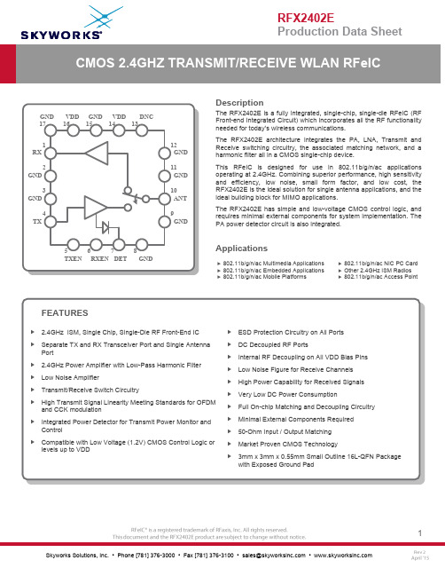
DescriptionThe RFX2402E is a fully integrated, single-chip, single-die RFeIC (RF Front-end Integrated Circuit) which incorporates all the RF functionality needed for today’s wireless communications.The RFX2402E architecture integrates the PA, LNA, Transmit and Receive switching circuitry, the associated matching network, and a harmonic filter all in a CMOS single-chip device.This RFeIC is designed for use in 802.11b/g/n/ac applications operating at 2.4GHz. Combining superior performance, high sensitivity and efficiency, low noise, small form factor, and low cost, the RFX2402E is the ideal solution for single antenna applications, and the ideal building block for MIMO applications.The RFX2402E has simple and low-voltage CMOS control logic, and requires minimal external components for system implementation. The PA power detector circuit is also integrated.Applications④ 802.11b/g/n/ac Multimedia Applications ④ 802.11b/g/n/ac Embedded Applications ④ 802.11b/g/n/ac Mobile Platforms ④ 802.11b/g/n/ac NIC PC Card ④ Other 2.4GHz ISM Radios ④ 802.11b/g/n/ac Access PointPIN ASSIGNMENTS:PINOUT DIAGRAM:RXGND GND TX TXENDETVDD GNDGNDANTGNDRXENGND DNC VDD GND(Top "See-Through" View)ABSOLUTE MAXIMUM RATINGS:Note: Sustained operation at or above the Absolute Maximum Ratings for any one or combinations of the above parameters may result in permanent damage to the device and is not recommended. All Maximum RF Input Power Ratings assume 50-Ohm terminal impedance.NOMINAL OPERATING CONDITIONS:Note 1: If control voltage can exceed 1.8V, a 1KΩ –10KΩ series resistor is recommended for the application circuit on each control line.Note2: For operation above +85 o C, use theθja as guidance for system design to assure the junction temperature will not exceed the maximum of +150 o C.TRANSMIT TECHNICAL PARAMETERS (VDD=3.3V, T=+25 o C)RECEIVE TECHNICAL PARAMETERS (VDD=3.3V, T=+25 o C)CONTROL SIGNAL DIAGRAM:RXENTXENCONTROL LOGIC TRUTH TABLE:“0” denotes low voltage stage (<0.3V) at Control Pins“X” denotes the don’t care statePACKAGE DIMENSIONS:A1AA1bDD2EE2eLMin0.50.000.202.901.652.901.650.450.35Nom0.550.020.253.001.703.001.700.500.40Max0.60.050.303.101.753.101.750.550.45Dimensions (mm)PACKAGE MARKINGPin 1 MarkSecond LineLot NumberThird LineDate CodePCB LAND PATTERN。

User GuideTN-QSFP-40G-xxCisco Compatible 40G QSFP+Optical Transceivers•High capacity: up to 44.4 Gbps per module•Compliant with SFF 8436 QSFP+ MSA•Single +3.3 V Power Supply•RoHS Compliant (all models)•Low Power Dissipation : SR4< 1.5 Watts, LR4 < 3.5w•Digital Diagnostic Monitoring (DMI and DDMI)•Class 1 Laser International Safety Standard IEC 60825 Compliant•40GBase-SR4: 4 lanes, up to 11.1Gbps per lane, Standard MPO connector•40GBase-LR4: 4 wavelength CWDM Mux/Demux design, up to 11.1Gbps per wavelength, Duplex LC connectorContentsIntroduction (1)Description (2)Ordering Information (2)Specifications and Standards (2)Optical Specifications (2)Application: Fiber Connection with QSFP+ (3)QSFP+ Unpacking (3)QSFP+ Installation (4)Cautions (4)Installing a QSFP+ Module (4)Fiber Cable Physical Characteristics (5)Connecting Fiber Cables (5)Removing a QSFP+ Module (5)Diagnostic Monitoring Interface (DMI) (6)Digital Diagnostics Monitoring Interface (DDMI) (7)For More Information (8)Contact Us (8)Compliance Information (9)Record of Revisions (10)IntroductionThe Transition Networks TN-QSFP-40G-xx series 40G QSFP+ optical transceivers are designed to install in any QSFP+ port allowing for 40GBase-X interfaces to the network through the QSFP+ connector.The TN-QSFP-40G-xx transceivers are Cisco compatible* and are designed for bi-directional serial-optical data communication such as 40G Ethernet.DescriptionTransition Networks’ QSFP+ modules fully comply with the Multi-Sourcing Agreement (MSA).This compliance allows our QSFP+ modules to be used in all other MSA compliant QSFP+ platforms. In addition, TN QSFP+ modules are also compatible with all Cisco QSFP+ based routers and switches, as well as Cisco’s IOS software. TN QSFP+ modules are not Cisco OEM brand modules. Ordering InformationProduct Number DescriptionTN-QSFP-40G-LR4 QSFP+ 40GBase-LR4, 1271nm, 1291nm, 1311nm, 1331nm, single mode (LC)[10km/6.2mi.] Link Budget: 7.0 dBTN-QSFP-40G-SR4 QSFP+ 40GBase-SR4, 850nm multimode (MPO) [400m/1313ft. on OM4, 300m/985ft. on OM3] Link Budget: 2.3 dBTN-QSFP-40G-LR4-3 QSFP+ 40GBase-LR4, 1271nm, 1291nm, 1311nm, 1331nm single mode (LC)[30km/18.7mi.] Link Budget: 9.0 dBSpecifications and StandardsThe TN-QSFP-40G-xx was designed to meet these standards and specifications:Optical SpecificationsThe Optical Specs for all Transition Networks’ SFPs are available on our Optical Devices webpage.Application: Fiber Connection with QSFP+Applications include: 40G Ethernet, 10G Ethernet, and Data Center Aggregation Connection.QSFP+UnpackingBefore you start installing the TN-QSFP-40G-xx, verify that the package contains the following items: o One TN-QSFP-40G-xx SFPo Two protective foam pieceso One Documentation PostcardNotify your sales representative immediately if any of the above items is missing or damaged. Save the packaging for possible future use.The optical ports of the QSFP+ transceiver must be terminated with an optical connector or with a dust plug. The QSFP+ transceiver must be operated within the specified temperature and voltage limits.QSFP+ InstallationCautions•The QSFP+ tranceiver module is keyed to only be installed one way. However, if forced the wrong way, damage may occur. •Avoid getting dust or other contaminants into the fiber bore of the QSFP+ transceiver module. •Clean the optic surfacees of the optical fiber before you plug them back in to the optical bores of another QSFP+ tranceiver module. • Each port must match the wavelength specifications on the other end of the cable, and the cablemust not exceed the specified cable length for reliable communications.Installing a QSFP+ Module1. Attach an ESD-preventive wrist strap to your wrist and to the ESD ground connector or a bare metalsurface on your chassis.2. Remove the QSFP+ transceiver module from its protective packaging. Note: Do not remove theoptical bore dust plugs until directed to do so in a later procedure.3. Check the slot orientation. Note that for some devices (e.g., S4224) some slots are “upside down”compared to other slots.4. Position the QSFP+device at the desired installation slot, with the label facing correctly.5. Carefully slide the QSFP+ device into the slot, aligning it with the internal installation guides.Triangleindicates bottomof SFP cageSFP Module Label side top of SFP moduleBaleClasp SwitchFully Inserted SFPSwitch 6. Ensure that the QSFP+device is firmly seated against the internal mating connector. To verify that theQSFP+ is seated and latched properly. a ) Grasp the QSFP+ by the sides and try to remove it without releasing the latch. b) If the QSFP+ can not be removed, it is installed and seated properly. If the QSFP+ can be removed, reinsert it and press harder with your thumb; repeat if necessary until it is latched securely into the socket.7. Connect the fiber cable to the fiber port connector of the QSFP+ device. Make sure the QSFP+release latch is in the up (closed) position when you insert the cable connector into the QSFP+.8. Remove the dust plug from the connector. Save the dust plug for future use.9. Attach an appropriate cable into the QSFP+ module port.10. Attach the other end of the cable into the other device.11. Observe the status LED(s). See the related manual for details.Fiber Cable Physical CharacteristicsThe fiber cable physical characteristics must meet or exceed IEEE 802.3ae specifications:•Single mode fiber (recommended): 9 μm•Multimode fiber (recommended): 62.5/125 μm•Multimode fiber (optional): 100/140, 85/140, 50/125 μmWarning: Visible and invisible laser radiation when open. DO NOT stare into laser beam or view directly with optical instruments. Failure to observe this warning could result in damage to your eyes or blindness. Connecting Fiber CablesTo install the fiber cable, do the following:1. Locate the appropriate fiber cable.2. Install the cable as shown below.Removing a QSFP+ModuleCaution: Be careful when removing the QSFP+ from a device. Some QSFP+ transceiver module temperatures may exceed 160°F (70°C) and be too hot to touch with bare hands. Note: Do not remove and replace the QSFP+ modules more often than necessary; excessive QSFP+ removing and replacing can shorten the useful life of the QSFP+.1. Attach an ESD-preventive wrist strap to your wrist and to the ESD ground connector or a bare metalsurface on your chassis.2. For future reattachment of fiber-optic cables, note which connector plug is send (TX) and which isreceive (RX).3. Remove the QSFP+ transceiver module:a. If the QSFP+ transceiver module has an actuator button latch, gently press the actuator buttonon the front of the QSFP+ transceiver module until it clicks and the latch mechanism releases the QSFP+ transceiver module from the socket connector. Grasp the actuator button between your thumb and index finger, and carefully pull the QSFP+ transceiver module straight out of the module slot.b. If the QSFP+ transceiver module has a bail clasp latch, pull the latch out and down to eject theQSFP+ transceiver module from the socket connector. If the bail clasp latch is obstructed and you cannot use your index finger to open it, use a small, flat-blade screwdriver or other long, narrow instrument to open the bail clasp latch. Grasp the QSFP+ transceiver module between your thumb and index finger, and carefully remove it from the socket.4. Replace the Dust Plug.5. Place the removed QSFP+ transceiver module in an antistatic bag or other protective package.Diagnostic Monitoring Interface (DMI)The following DMI port screen and explanation table contains brief definitions of the DMI support offered on some QSFP+ transceiver modules. For further information, see the help option on the CPSMM-xxx, SNMP agent, or Transition Networks Focal Point or ION System GUI. Note: This feature is not availableon all devices and may vary between products. See the related manual for more information.DMI Parameter Description DMI Rx PowerMeasured receive optical power in microwatts and in decibels relative to 1mW. DMI Rx PowerAlarmAlarm status of measured receive optical power. DMI Temp Internally measured temperature of transceiver in degrees Celsius and degreesFarenheit.DMI Temp Alarm Alarm status for internally measured temperature of the transceiver.DMI Bias Current Measured transmit bias current in microamperes.DMI Bias Alarm Alarm status for measured transmit bias current for the interface.DMI Tx Power Measured transmit power in microwatts and in decibels relative to 1mW. DMI Tx Power Alarm Alarm status of measured transmit power.Rx Power Intrusion Threshold Tells the converter to stop passing traffic when the receive power drops belowthe new threshold. This feature is sometimes referred to as 'Intrusion Detection,' since tapping into a fiber to intercept traffic leads to a reduction in receive power.This value can be entered in microwatts or in decibels relative to 1mW.TN-QSFP+ distances, TX power, RX power, and link budgets can be found on Transition Netwoks’ website, document “SFP/XFP Fiber and Copper Connectors.” See at https:///. The fiber optic transmitters on this device meet Class I Laser safety requirements per IEC-825/CDRH standards and comply with 21 CFR1040.10 and 21CFR1040.11.WARNING: Visible and invisible laser radiation when open. Do not stare into the beam or view the beam directly with optical instruments. Failure to observe this warning could result in an eye injury or blindness. IMPORTANT: Copper based media ports such as Twisted Pair (TP) Ethernet, USB, RS232, RS422, RS485, DS1, DS3, Video Coax, etc., are intended to be connected to intra-building (inside plant) linksegments that are not subject to lightening transients or power faults. Copper-based media ports such as Twisted Pair (TP) Ethernet, USB, RS232, RS422, RS485, DS1, DS3, Video Coax, etc., are NOT to be connected to inter-building (outside plant) link segments that are subject to lightening transients or power faults.Digital Diagnostics Monitoring Interface (DDMI)DDMI (Digital Diagnostics Monitoring Interface) provides enhanced digital DMI for optical transceivers which allows real time access to device operating parameters.This section contains brief definitions of the DDMI support offered on some QSFP+ transceiver modules. For further information, see the help option or User Guide for the S3290, S4140, S4212, and S4224. Note: This feature is not available on all devices and may vary between products.The Transceiver Information and DDMI Information sections are described below. DDMI ParameterDescription DMIRx Power (uW) Intrusion Threshold; a level for Rx Power on the Fiber port. If the DMI read value falls below the preset value, an intrusion is detected, and a trap is generated. The default is 0 uW. The range is 0 - 65,535 uW. PortThe device’s port number. VendorThe QSFP+ vendor’s name (e.g., Transition ). Part NumberThe QSFP+ vendor Part number provided by the QSFP+ vendor (TN-10GSFP-SR ). Serial NumberThe QSFP+ Vendor Serial number provided by the QSFP+ vendor (e.g., 8672105). RevisionThe QSFP+ vendor Revision level for part number provided by the QSFP+ vendor. Data CodeThe vendor's manufacturing date code (e.g ., 2011-08-09). TranseiverThe Transceiver compatibility (e.g., 1000BASE_SX or 10G ). CurrentThe current value of temperature, voltage, TX bias, TX power, and RX power. High Alarm ThresholdThe high alarm threshold value of temperature, voltage, TX bias, TX power, and RX power. High Warn ThresholdThe high warn threshold value of temperature, voltage, TX bias, TX power, and RX power. Low Warn ThresholdThe low warn threshold value of temperature, voltage, TX bias, TX power, and RX power. Low Alarm Threshold The low alarm threshold value of temperature, voltage, TX bias, TX power,and RX power.For More InformationTechnical information in this document is subject to change without notice. For more information see the TN SFP webpage.40 Gigabit Ethernet ("40GbE" or "40G") Port Types (40GBASE-CR4, 40GBASE-KR4, 40GBASE-SR4, 40GBASE-LR4, 40GBASE-ER4, 40GBASE-FR, 40GBASE-T) ITU standards descriptions include:40GBASE-SR4 ("short range") is a port type for multi-mode fiber and uses 850 nm lasers. Its Physical Coding Sublayer 64b/66b PCS is defined in IEEE 802.3 Clause 82 and its Physical Medium Dependent PMD in Clause 86. It uses four lanes of multi-mode fiber delivering serialized data at a rate of 10.3125 Gbit/s per lane. 40GBASE-SR4 has a reach of 100 m on OM3 and 150m on OM4. There is a longer range variant 40GBASE-eSR4 with a reach of 300 m on OM3 and 400 m on OM4. This extended reach is equivalent to the reach of 10GBASE-SR.40GBASE-LR4 ("long range") is a port type for single-mode fiber and uses 1300 nm lasers. Its Physical Coding Sublayer 64b/66b PCS is defined in IEEE 802.3 Clause 82 and its Physical Medium Dependent PMD in Clause 87. It uses four wavelengths delivering serialized data at a rate of 10.3125 Gbit/s per wavelength.The amendment to IEEE Std 802.3-2008 includes changes to IEEE Std 802.3-2008 and adds Clause 80 through Clause 88, Annex 83A through Annex 83C, Annex 85A, and Annex 86A. This amendment includes IEEE 802.3 Media Access Control (MAC) parameters, Physical Layer specifications, and management parameters for the transfer of IEEE 802.3 format frames at 40 Gb/s and 100 Gb/s.EIA SFF-8436 Rev 4.8 section 5.5 Color Coding and Labeling of QSFP+ Modules: An exposed feature of the QSFP+ Module (a feature or surface extending outside of the bezel) shall be color coded as follows: Beige for 850nm, Blue for 1310nm, and White for 1550nm. For more information seeftp:///sff/SFF-8436.PDF.Contact UsTechnical Support: Technical support is available 24-hours a dayUS and Canada: 1-800-260-1312International: 00-1-952-941-7600Main Officetel: +1.952.941.7600 | toll free: 1.800.526.9267 | fax: 952.941.2322******************** | ************************** | ******************************AddressTransition Networks10900 Red Circle DriveMinnetonka, MN 55343, U.S.A.Compliance InformationClass I Laser ComplianceThis product has been tested and found to comply with the limits for FDA Class I laser for IEC60825,EN60825, and 21CFR1040 specifications.Translated Safety WarningsWarning Class I laser product. Advarsel Laserprodukt av klasse I.Waarschuwing Klasse-I laser produkt. Aviso Produto laser de classe I.Varoitus Luokan I lasertuote. ¡Advertencia! Producto láser Clase I.Attention Produit laser de classe I Varning! Laserprodukt av klass I.Warnung Laserprodukt der Klasse I. Aviso Produto a laser de classe I.Avvertenza Prodotto laser di Classe I. Advarsel Klasse I laserprodukt.FCC RegulationsThis equipment has been tested and found to comply with the limits for a Class A digital device, pursuant to Part 15 of the FCC rules. These limits are designed to provide reasonable protection against harmful interference when the equipment is operated in a commercial environment. This equipment generates, uses and can radiate radio frequency energy and, if not installed and used in accordance with the instruction manual, may cause harmful interference to radio communications.Operation of this equipment in a residential area is likely to cause harmful interference, in which case the user will be required to correct the interference at the user's own expense.Canadian RegulationsThis digital apparatus does not exceed the Class A limits for radio noise for digital apparatus set out on the radio interference regulations of the Canadian Department of Communications.Le présent appareil numérique n'émet pas de bruits radioélectriques dépassant les limites applicables aux appareils numériques de la Class A prescrites dans le Règlement sur le brouillage radioélectrique édicté par le ministère des Communications du Canada.European RegulationsWarningThis is a Class A product. In a domestic environment this product may cause radio interference in which case the user may be required to take adequate measures.Achtung !Dieses ist ein Gerät der Funkstörgrenzwertklasse A. In Wohnbereichen können bei Betrieb dieses Gerätes Rundfunkstörungen auftreten. In diesem Fäll is der Benutzer für Gegenmaßnahmen verantwortlich.Attention !Ceci est un produit de Classe A. Dans un environment domestique, ce produit risque de créer desinterférences radioélectriques, il appartiendra alors à l'utilsateur de prende les measures spécifiquesappropriées.In accordance with European Union Directive 2002/96/EC of the European Parliament and of theCouncil of 27 January 2003, Transition Networks will accept post usage returns of this product for proper disposal. The contact information for this activity can be found in the 'Contact Us' portion of this document.Der Anschluss dieses Gerätes an ein öffentlickes Telekommunikationsnetz in den EGMitgliedstaatenverstösst gegen die jeweligen einzelstaatlichen Gesetze zur Anwendung der Richtlinie 91/263/EWG zur Angleichung der Rechtsvorschriften der Mitgliedstaaten über Telekommunikationsendeinrichtungen einschliesslich der gegenseitigen Anerkennung ihrer Konformität.CAUTION: RJ connectors are NOT INTENDED FOR CONNECTION TO THE PUBLICTELEPHONE NETWORK. Failure to observe this caution could result in damage to the publictelephone network.Der Anschluss dieses Gerätes an ein öffentlickes Telekommunikationsnetz in den EGMitgliedstaatenverstösst gegen die jeweligen einzelstaatlichen Gesetze zur Anwendung der Richtlinie 91/263/EWG zur Angleichung der Rechtsvorschriften der Mitgliedstaaten über Telekommunikationsendeinrichtungen einschliesslich der gegenseitigen Anerkennung ihrer Konformität.Record of RevisionsRev Date NotesA 8/29/16 Initial release.B 9/6/16 Incorporate editorial changes.Trademarks: All trademarks and registered trademarks are the property of their respective owners.Copyright restrictions: © 2016 Transition Networks. All rights reserved. No part of this work may be reproduced or used in any form or by any means - graphic, electronic or mechanical - without written permission from Transition Networks.Transition Networks TN-QSFP-40G-xx User Guide33684 Rev. B https:///Page 11 of 11。
![[指导]Si47xx编程指南(部分翻译)](https://img.taocdn.com/s1/m/f3f14210773231126edb6f1aff00bed5b9f37306.png)
SI4740 FM/RDS接收命令和道具FM接收状态回应命令0x01:上电启动关电到上电的启动进程,这个启动可以从内部存储器或系统控制下载补丁发生,为了确认补丁和器件内部库版本一致,库版本必须通过发出上电命令FUNC=1(询问库ID)证实,器件返回响应,包含版本,然后转入关电模式,器件然后可以通过发出上电命令FUNC=1(AM/SW/FM接收)进入上电模式并且补丁可以应用,看178页7.2节“从组成补丁上电”。
上电命令配置LOUT(Pin3)和ROUT(Pin4)的状态位模拟音频模式,GPO2/INT(Pin18)为中断操作。
命令字节:2响应字节:none(FUNC=1),7(FUNC=15)P106四、命令和响应命令控制指令,如上电、关电、调谐频率,是一字节,协议给命令或修改命令,例如,TX_TUNE_ FREQ命令后,协议要求发送调谐频率,协议是一字节,每一个命令最多可以要求7个协议,在系统传送了命令和相关指令后响应提供了系统状态信息。
所有命令返回一个字节指示中断状态和CTS,命令最多可以有多达15个字节响应。
一个完整的可用命令列表见“5、命令和特性”表 2 使用TX_TUNE_FREQ命令特性是在上电后用来改进默认的器件运行并产生配置的特殊的命令协议。
表 3 使用设置特性命令系统控制中执行命令和响应程序不同于这3个总线模式,见168页“章6,控制接口”5.3. AM/SW/LW接收命令和特性中波、短波和长波使用同样的AM_SW_L W元件,对这些功能的命令是相同的,为简单起见,AM_SW_LW的命令和特性仅用AM代替,AM_SW_LW 之中主要是频率范围不同。
频率范围短波:2.3MHz ~ 23MHz,间隔5kHz中波(美国):522kHz ~ 1.71MHz,间隔10kHz中波(亚洲):522kHz ~ 1.71MHz,间隔9kHz长波:153kHz ~ 279kHz,间隔9kHzTable 14、AM/SW/LW接收状态响应5.3.1 AM/SW/LW接收命令命令0x01、上电发起启动进程将器件从关电进入上电模式,这个启动可以从内部器件存储器或系统控制下载补丁发生。
EDS-G4014Series8G+62.5GbE-port full Gigabit managed Ethernet switchesFeatures and Benefits•Developed according to the IEC62443-4-1and compliant with the IEC62443-4-2industrial cybersecurity standards•Turbo Ring and Turbo Chain(recovery time<50ms@250switches),andRSTP/STP for network redundancy•Wide range of power input options for flexible deployment•Compact and flexible housing design to fit into confined spaces•Supports MXstudio for easy,visualized industrial network management•Increased bandwidth capabilities with fiber SFP slots supporting up to2.5GbpsCertificationsIntroductionThe EDS-G4014Series is equipped with eight Gigabit Ethernet ports and six2.5Gbps fiber-optic ports,making it ideal for upgrading an existing network to Gigabit speed or building a new full Gigabit backbone.Gigabit transmission speed increases bandwidth for higher performance and can transfer large amounts of triple-play services across a network quickly.Redundant Ethernet technologies such as Turbo Ring,Turbo Chain,and RSTP/STP increase the reliability of your system and improve the availability of your network backbone.The EDS-G4014Series is designed specifically for demanding applications such as video and process monitoring,ITS,and DCS systems,all of which can benefit from a scalable backbone.The EDS-G4014Series is compliant with the IEC62443-4-2and IEC62443-4-1Industrial Cybersecurity certifications,which cover both product security and secure development life-cycle requirements,helping our customers meet the compliance requirements of secure industrial network design.SpecificationsEthernet Interface10/100/1000BaseT(X)Ports(RJ45connector)8Auto MDI/MDI-X connectionAuto negotiation speedFull/Half duplex mode100/1000/2500BaseSFP Ports41000/2500BaseSFP Ports2Standards IEEE802.3for10BaseTIEEE802.3u for100BaseT(X)IEEE802.3ab for1000BaseT(X)IEEE802.3z for1000BaseXIEEE802.3bz for2.5GBaseXIEEE802.3x for flow controlIEEE802.3ad for Port Trunk with LACPIEEE802.1Q for VLAN TaggingIEEE802.1D-2004for Spanning Tree ProtocolIEEE802.1w for Rapid Spanning Tree ProtocolIEEE802.1p for Class of ServiceIEEE802.1X for authenticationEthernet Software FeaturesFilter GMRP,GVRP,GARP,802.1Q VLAN,IGMP Snooping v1/v2/v3,IGMP Querier Management IPv4/IPv6,Flow control,Back Pressure Flow Control,DHCP Server/Client,ARP,RARP,LLDP,Port Mirror,Linkup Delay,SMTP,SNMP Trap,SNMP Inform,SNMPv1/v2c/v3,RMON,TFTP,SFTP,HTTP,HTTPS,Telnet,Syslog,Private MIBMIB P-BRIDGE MIB,Q-BRIDGE MIB,IEEE8021-SPANNING-TREE-MIB,IEEE8021-PAE-MIB,IEEE8023-LAG-MIB,LLDP-EXT-DOT1-MIB,LLDP-EXT-DOT3-MIB,SNMPv2-MIB,RMON MIB Groups1,2,3,9Redundancy Protocols STP,RSTP,Turbo Ring v2,Turbo Chain,Ring Coupling,Dual-Homing,LinkAggregation,MSTPSecurity Broadcast storm protection,Rate Limit,Trust access control,Static Port Lock,MACSticky,HTTPS/SSL,SSH,RADIUS,TACACS+,Login and Password Policy,Accesscontrol listTime Management SNTP,NTP Server/Client,NTP AuthenticationProtocols IPv4/IPv6,TCP/IP,UDP,ICMP,ARP,RARP,TFTP,DNS,NTP Client,DHCP Server,DHCP Client,802.1X,QoS,HTTPS,HTTP,Telnet,SMTP,SNMPv1/v2c/v3,RMON,SyslogSwitch PropertiesMAC Table Size16KJumbo Frame Size9.216KBMax.No.of VLANs256VLAN ID Range VID1to4094IGMP Groups512Priority Queues4Packet Buffer Size1MBLED InterfaceLED Indicators PWR1,PWR2,STATE,FAULT,MSTR/HEAD,CPLR/TAIL,SYNCSerial InterfaceConsole Port RS-232(TxD,RxD,GND),8-pin RJ45(115200,n,8,1)USB InterfaceUSB Connector USB Type A(Reserved)Input/Output InterfaceAlarm Contact Channels1,Relay output with current carrying capacity of1A@24VDCDigital Input Channels1Digital Inputs+13to+30V for state1-30to+3V for state0Max.input current:8mAButtons Reset buttonDIP Switch ConfigurationDIP Switches Turbo Ring,Master,Coupler,ReservePower ParametersConnection2removable4-contact terminal block(s)Pre-installed Power Module-LV/-LV-T models:PWR-100-LV-HV/-HV-T models:PWR-105-HV-INote The EDS-G4014Series supports modular power supplies.The model names and powerparameters are determined by the installed power module.For example:EDS-G4014-6QGS-T+PWR-100-LV=EDS-G4014-6QGS-LV-TEDS-G4014-6QGS-T+PWR-105-HV-I=EDS-G4014-6QGS-HV-TIf you install a different power module,refer to the specifications of the correspondingmodel.For example,if you replace the power module of the EDS-G4014-6QGS-LV-Twith the PWR-105-HV-I,refer to the specifications of the EDS-G4014-6QGS-HV-T. Input Voltage-LV/-LV-T models:12/24/48VDC,Redundant dual inputs-HV/-HV-T models:110/220VDC/VAC,Single inputOperating Voltage-LV/-LV-T models:9.6to60VDC-HV/-HV-T models:88to300VDC,85to264VACInput Current-LV/-LV-T models:12-48VDC,1.50-0.40A or24VDC,0.70A-HV/-HV-T models:110-220VAC,50-60Hz,0.30-0.20A or110-220VDC,0.30-0.20A Power Consumption(Max.)EDS-G4014-6QGS-LV(-T)models:14.91WEDS-G4014-6QGS-HV(-T)models:17.32WOverload Current Protection SupportedReverse Polarity Protection SupportedPhysical CharacteristicsIP Rating IP40Dimensions55x140x122.5mm(2.17x5.51x4.82in)Weight846g(1.87lb)Installation DIN-rail mounting,Wall mounting(with optional kit)Housing MetalEnvironmental LimitsOperating Temperature Standard Models:-10to60°C(14to140°F)Wide Temp.Models:-40to75°C(-40to167°F)Ambient Relative Humidity5to95%(non-condensing)Standards and CertificationsIndustrial Cybersecurity IEC62443-4-1IEC62443-4-2Safety UL61010-2-201,EN62368-1(LVD)EMC EN55032/35,EN61000-6-2/-6-4EMI CISPR32,FCC Part15B Class AEMS IEC61000-4-2ESD:Contact:8kV;Air:15kVIEC61000-4-3RS:80MHz to1GHz:20V/mIEC61000-4-4EFT:Power:4kV;Signal:4kVIEC61000-4-5Surge:Power:4kV;Signal:4kVIEC61000-4-6CS:10VIEC61000-4-8PFMFMaritime-LV/-LV-T models:DNV,ABS,NK,LRVibration IEC60068-2-6Shock IEC60068-2-27Freefall IEC60068-2-32Railway EN50121-4Traffic Control NEMA TS2Power Substation IEC61850-3,IEEE1613Class1Hazardous Locations Class I Division2,ATEX,IECExMTBFTime EDS-G4014-6QGS-LV/LV-T models:994,797hrsEDS-G4014-6QGS-HV/HV-T models:487,613hrsWarrantyWarranty Period5yearsDetails See /warrantyPackage ContentsDevice1x EDS-G4014Series switchDocumentation1x quick installation guide1x product notice,Simplified Chinese1x product certificates of quality inspection,Simplified Chinese1x warranty cardDimensionsOrdering InformationEDS-G4014-6QGS-LV8429.6to60VDC PWR-100-LV-10to60°C EDS-G4014-6QGS-LV-T8429.6to60VDC PWR-100-LV-40to75°CEDS-G4014-6QGS-HV84288to300VDC,85to264VACPWR-105-HV-I-10to60°CEDS-G4014-6QGS-HV-T84288to300VDC,85to264VACPWR-105-HV-I-40to75°CAccessories(sold separately)SFP ModulesSFP-1GEZXLC SFP module with11000BaseEZX port with LC connector for110km transmission,0to60°C operatingtemperatureSFP-1GEZXLC-120SFP module with11000BaseEZX port with LC connector for120km transmission,0to60°C operatingtemperatureSFP-1GLHLC SFP module with11000BaseLH port with LC connector for30km transmission,0to60°C operatingtemperatureSFP-1GLHXLC SFP module with11000BaseLHX port with LC connector for40km transmission,0to60°C operatingtemperatureSFP-1GLSXLC SFP module with11000BaseLSX port with LC connector for1km/2km transmission,0to60°Coperating temperatureSFP-1GLXLC SFP module with11000BaseLX port with LC connector for10km transmission,0to60°C operatingtemperatureSFP-1GSXLC SFP module with11000BaseSX port with LC connector for300m/550m transmission,0to60°Coperating temperatureSFP-1GZXLC SFP module with11000BaseZX port with LC connector for80km transmission,0to60°C operatingtemperatureSFP-1GLHLC-T SFP module with11000BaseLH port with LC connector for30km transmission,-40to85°C operatingtemperatureSFP-1GLHXLC-T SFP module with11000BaseLHX port with LC connector for40km transmission,-40to85°Coperating temperatureSFP-1GLSXLC-T SFP module with11000BaseLSX port with LC connector for1km/2km transmission,-40to85°Coperating temperatureSFP-1GLXLC-T SFP module with11000BaseLX port with LC connector for10km transmission,-40to85°C operatingtemperatureSFP-1GSXLC-T SFP module with11000BaseSX port with LC connector for300m/550m transmission,-40to85°Coperating temperatureSFP-1GZXLC-T SFP module with11000BaseZX port with LC connector for80km transmission,-40to85°C operatingtemperatureSFP-1G10ALC WDM-type(BiDi)SFP module with11000BaseSFP port with LC connector for10km transmission;TX1310nm,RX1550nm,0to60°C operating temperatureSFP-1G10BLC WDM-type(BiDi)SFP module with11000BaseSFP port with LC connector for10km transmission;TX1550nm,RX1310nm,0to60°C operating temperatureSFP-1G20ALC WDM-type(BiDi)SFP module with11000BaseSFP port with LC connector for20km transmission;TX1310nm,RX1550nm,0to60°C operating temperatureSFP-1G20BLC WDM-type(BiDi)SFP module with11000BaseSFP port with LC connector for20km transmission;TX1550nm,RX1310nm,0to60°C operating temperatureSFP-1G40ALC WDM-type(BiDi)SFP module with11000BaseSFP port with LC connector for40km transmission;TX1310nm,RX1550nm,0to60°C operating temperatureSFP-1G40BLC WDM-type(BiDi)SFP module with11000BaseSFP port with LC connector for40km transmission;TX1550nm,RX1310nm,0to60°C operating temperatureSFP-1G10ALC-T WDM-type(BiDi)SFP module with11000BaseSFP port with LC connector for10km transmission;TX1310nm,RX1550nm,-40to85°C operating temperatureSFP-1G10BLC-T WDM-type(BiDi)SFP module with11000BaseSFP port with LC connector for10km transmission;TX1550nm,RX1310nm,-40to85°C operating temperatureSFP-1G20ALC-T WDM-type(BiDi)SFP module with11000BaseSFP port with LC connector for20km transmission;TX1310nm,RX1550nm,-40to85°C operating temperatureSFP-1G20BLC-T WDM-type(BiDi)SFP module with11000BaseSFP port with LC connector for20km transmission;TX1550nm,RX1310nm,-40to85°C operating temperatureSFP-1G40ALC-T WDM-type(BiDi)SFP module with11000BaseSFP port with LC connector for40km transmission;TX1310nm,RX1550nm,-40to85°C operating temperatureSFP-1G40BLC-T WDM-type(BiDi)SFP module with11000BaseSFP port with LC connector for40km transmission;TX1550nm,RX1310nm,-40to85°C operating temperatureSFP-1FELLC-T SFP module with1100Base single-mode with LC connector for80km transmission,-40to85°Coperating temperatureSFP-1FEMLC-T SFP module with1100Base multi-mode,LC connector for2/4km transmission,-40to85°C operatingtemperatureSFP-1FESLC-T SFP module with1100Base single-mode with LC connector for40km transmission,-40to85°Coperating temperatureSFP-2.5GLSLC-T SFP module with12.5GBaseFX port with LC connector,single-mode,for20km transmission,-40to85°C operating temperatureSFP-2.5GSLHLC-T SFP module with12.5GBaseFX port with LC connector,single-mode,for45km transmission,-40to85°C operating temperatureSFP-2.5GMLC-T SFP module with12.5GBaseFX port with LC connector,multi-mode,for170,200,550,600mtransmission,-40to85°C operating temperatureSFP-2.5GSLC-T SFP module with12.5GBaseFX port with LC connector,single-mode,for5km transmission,-40to85°C operating temperaturePower SuppliesHDR-60-2460W/2.5A DIN-rail24VDC power supply,universal85to264VAC or120to370VDC input voltage,-30to70°C operating temperatureNDR-120-24120W/5.0A DIN-rail24VDC power supply,universal90to264VAC or127to370VDC input voltage,-20to70°C operating temperatureNDR-120-48120W/2.5A DIN-rail48VDC power supply,universal90to264VAC or127to370VDC input voltage,-20to70°C operating temperatureNDR-240-48240W/5.0A DIN-rail48VDC power supply,universal90to264VAC or127to370VDC input voltage,-20to70°C operating temperatureMDR-40-24DIN-rail24VDC power supply with40W/1.7A,85to264VAC,or120to370VDC input,-20to70°Coperating temperatureMDR-60-24DIN-rail24VDC power supply with60W/2.5A,85to264VAC,or120to370VDC input,-20to70°Coperating temperature©Moxa Inc.All rights reserved.Updated Nov01,2022.This document and any portion thereof may not be reproduced or used in any manner whatsoever without the express written permission of Moxa Inc.Product specifications subject to change without notice.Visit our website for the most up-to-date product information.。
AWK-3131A SeriesIndustrial IEEE802.11a/b/g/n wireless AP/bridge/clientFeatures and Benefits•IEEE802.11a/b/g/n AP/bridge/client support•Easy setup and deployment with AeroMag•Millisecond-level Client-based Turbo Roaming1•Complete redundancy with AeroLink Protection•Integrated antenna and power isolation•-40to75°C operating temperature range(-T models)•5GHz DFS channel supportCertificationsIntroductionThe AWK-3131A3-in-1industrial wireless AP/bridge/client meets the growing need for faster data transmission speeds by supporting IEEE802.11n technology with a net data rate of up to300Mbps.The AWK-3131A is compliant with industrial standards and approvals covering operating temperature,power input voltage,surge,ESD,and vibration.The two redundant DC power inputs increase the reliability of the power supply,and the AWK-3131A can be powered via PoE to make deployment easier.The AWK-3131A can operate on either the2.4or5GHz bands and is backwards-compatible with existing802.11a/b/g deployments to future-proof your wireless investments.Advanced802.11n Industrial Wireless Solution•802.11a/b/g/n compliant AP/bridge/client for flexible deployment•Software optimized for long-distance wireless communication with up to1km line of sight and external high-gain antenna(available only on5 GHz)•Supports60clients connected concurrently•DFS channel support allows a wider range of5GHz channel selection to avoid interference from existing wireless infrastructureAdvanced Wireless Technology•AeroMag supports error-free setup of your industrial applications’fundamental WLAN settings•Seamless roaming with client-based Turbo Roaming1for<150ms roaming recovery time between APs(Client Mode)•Supports AeroLink Protection for creating a redundant wireless link(<300ms recovery time)between APs and their clientsIndustrial Ruggedness•Integrated antenna and power isolation designed to provide500V insulation protection against external electrical interference•Hazardous location wireless communication with Class I Div.II and ATEX Zone2certifications•-40to75°C wide operating temperature models(-T)provided for smooth wireless communication in harsh environmentsSpecificationsWLAN InterfaceWLAN Standards802.11a/b/g/n802.11i Wireless SecurityModulation Type DSSSMIMO-OFDMOFDMFrequency Band for US(20MHz operating channels) 2.412to2.462GHz(11channels)1.The Turbo Roaming recovery time indicated herein is an average of test results documented,in optimized conditions,across APs configured with interference-free20-MHz RF channels,WPA2-PSK security,and default Turbo Roaming parameters.The clients are configured with3-channel roaming at100Kbps traffic load.Other conditions may also impact roaming performance.For more information about Turbo Roaming parameter settings,refer to the product manual.5.180to5.240GHz(4channels)5.260to5.320GHz(4channels)25.500to5.700GHz(11channels)25.745to5.825GHz(5channels)Frequency Band for EU(20MHz operating channels) 2.412to2.472GHz(13channels)5.180to5.240GHz(4channels)5.260to5.320GHz(4channels)25.500to5.700GHz(11channels)2Frequency Band for JP(20MHz operating channels) 2.412to2.484GHz(14channels)5.180to5.240GHz(4channels)5.260to5.320GHz(4channels)25.500to5.700GHz(11channels)2Wireless Security WEP encryption(64-bit and128-bit)WPA/WPA2-Enterprise(IEEE802.1X/RADIUS,TKIP,AES)WPA/WPA2-PersonalTransmission Rate802.11b:1to11Mbps802.11a/g:6to54Mbps802.11n:6.5to300MbpsTransmitter Power for802.11a23±1.5dBm@6to24Mbps21±1.5dBm@36Mbps20±1.5dBm@48Mbps18±1.5dBm@54MbpsTransmitter Power for802.11n(5GHz)23±1.5dBm@MCS0/820MHz18±1.5dBm@MCS7/1520MHz23±1.5dBm@MCS0/840MHz17±1.5dBm@MCS7/1540MHzTransmitter Power for802.11b26±1.5dBm@1Mbps26±1.5dBm@2Mbps26±1.5dBm@5.5Mbps25±1.5dBm@11MbpsTransmitter Power for802.11g23±1.5dBm@6to24Mbps21±1.5dBm@36Mbps19±1.5dBm@48Mbps18±1.5dBm@54MbpsTransmitter Power for802.11n(2.4GHz)23±1.5dBm@MCS0/820MHz18±1.5dBm@MCS7/1520MHz23±1.5dBm@MCS0/840MHz17±1.5dBm@MCS7/1540MHzTransmitter Power2.4GHz26dBm18dBm18dBm5GHz(UNII-1)23dBm21dBm21dBm5GHz(UNII-2)23dBm21dBm21dBm5GHz(UNII-2e)23dBm23dBm23dBm5GHz(UNII-3)23dBm––Note:Based on regional regulations,the maximum transmission power allowed onthe UNII bands is restricted in the firmware,as indicated above.Receiver Sensitivity for802.11a(measured at5.680 GHz)Typ.-90@6Mbps Typ.-88@9Mbps Typ.-88@12Mbps Typ.-85@18Mbps Typ.-81@24Mbps2.DFS(Dynamic Frequency Selection)channel support:In AP mode,when a radar signal is detected,the device will automatically switch to another channel.However,according to regulations,after switching channels,a60-second availability check period is required before starting the service.Typ.-78@36Mbps Typ.-74@48Mbps Typ.-72@54Mbps Note3Receiver Sensitivity for802.11n(5GHz;measured at 5.680GHz)Typ.-69dBm@MCS720MHz Typ.-71dBm@MCS1520MHz Typ.-63dBm@MCS740MHz Typ.-68dBm@MCS1540MHz Note3Receiver Sensitivity for802.11b(measured at2.437 GHz)Typ.-93dBm@1Mbps Typ.-93dBm@2Mbps Typ.-93dBm@5.5Mbps Typ.-88dBm@11MbpsReceiver Sensitivity for802.11g(measured at2.437 GHz)Typ.-88dBm@6Mbps Typ.-86dBm@9Mbps Typ.-85dBm@12Mbps Typ.-85dBm@18Mbps Typ.-85dBm@24Mbps Typ.-82dBm@36Mbps Typ.-78dBm@48Mbps Typ.-74dBm@54MbpsReceiver Sensitivity for802.11n(2.4GHz;measured at2.437GHz)Typ.-70dBm@MCS720MHz Typ.-69dBm@MCS1520MHz Typ.-67dBm@MCS740MHz Typ.-67dBm@MCS1540MHzWLAN Operation Mode Access point,Client,Client-Router,Master,Slave,SnifferAntenna External,2/2dBi,Omni-directionalAntenna Connectors QMAEthernet InterfacePoE Ports(10/100/1000BaseT(X),RJ45connector)1Standards IEEE802.1D-2004for Spanning Tree ProtocolIEEE802.1Q for VLAN TaggingIEEE802.1w for Rapid Spanning Tree ProtocolIEEE802.1X for authenticationIEEE802.3for10BaseTIEEE802.3ab for1000BaseT(X)IEEE802.3af for PoEIEEE802.3u for100BaseT(X)Ethernet Software FeaturesManagement DHCP Server/Client,DNS,HTTP,IPv4,LLDP,Proxy ARP,SMTP,SNMPv1/v2c/v3,Syslog,TCP/IP,Telnet,UDP,Wireless Search Utility,VLAN,MXview,MXconfig Redundancy Protocols RSTP,STPSecurity HTTPS/SSL,RADIUS,SSHTime Management SNTP ClientUnicast Routing Static RouteFirewallFilter ICMP,MAC address,IP protocol,Port-basedSerial InterfaceConsole Port RS-232,8-pin RJ453.Due to a limitation in the receiver sensitivity performance for channels153and161,it is recommended to avoid using these channels in your critical applications.LED InterfaceLED Indicators PWR1,PWR2,PoE,FAULT,STATE,SIGNAL,WLAN,LANInput/Output InterfaceDigital Inputs2Max.input current:8mA+13to+30V for state1+3to-30V for state0Alarm Contact Channels Relay output with current carrying capacity of1A@24VDCButtons Reset buttonPhysical CharacteristicsHousing MetalIP Rating IP30Dimensions52.7x135x105mm(2.08x5.32x4.13in)Weight860g(1.9lb)Installation DIN-rail mounting,Wall mounting(with optional kit)Power ParametersInput Current0.6A@12VDC,0.15A@48VDCInput Voltage12to48VDC,Redundant dual inputs,48VDC Power-over-EthernetPower Connector1removable10-contact terminal block(s)Power Consumption7.2W(max.)Reverse Polarity Protection SupportedEnvironmental LimitsOperating Temperature Standard Models:-25to60°C(-13to140°F)Wide Temp.Models:-40to75°C(-40to167°F)Storage Temperature(package included)-40to85°C(-40to185°F)Ambient Relative Humidity5to95%(non-condensing)Standards and CertificationsEMC EN61000-6-2/-6-4EMI CISPR32,FCC Part15B Class BEMS IEC61000-4-2ESD:Contact:8kV;Air:15kVIEC61000-4-3RS:80MHz to1GHz:3V/mIEC61000-4-4EFT:Power:2kV;Signal:2kVIEC61000-4-5Surge:Power:2kV;Signal:1kVIEC61000-4-6CS:3VIEC61000-4-8PFMFHazardous Locations ATEX,Class I Division2,IECExRadio IDA,EN300328,EN301489-1/17,EN301893,FCC ID SLE-WAPN008,MIC,NCC,RCM,SRRC,WPC,KC,RCMSafety EN60950-1,UL60950-1Vibration IEC60068-2-6MTBFTime570,854hrsStandards Telcordia SR332WarrantyWarranty Period5yearsDetails See /warrantyPackage ContentsDevice1x AWK-3131A Series wireless AP/bridge/clientInstallation Kit2x cap,plastic,for RJ45port1x DIN-rail kit1x cable holder with screwAntenna2x2.4/5GHz antennaDocumentation1x quick installation guide1x warranty cardDimensionsOrdering InformationModel Name Band Standards Operating Temp. AWK-3131A-EU EU802.11a/b/g/n-25to60°C AWK-3131A-EU-T EU802.11a/b/g/n-40to75°C AWK-3131A-JP JP802.11a/b/g/n-25to60°C AWK-3131A-JP-T JP802.11a/b/g/n-40to75°C AWK-3131A-US US802.11a/b/g/n-25to60°C AWK-3131A-US-T US802.11a/b/g/n-40to75°CAccessories(sold separately)AntennasANT-WDB-ANF-0407 2.4/5GHz,omni-directional antenna,4/7dBi,N-type(male)ANT-WDB-ANF-0609 2.4/5GHz,omni-directional antenna,6/9dBi,N-type(female)ANT-WDB-ANM-0306 2.4/5GHz,omni-directional antenna,3/6dBi,N-type(male)ANT-WDB-ANM-0407 2.4/5GHz,dual-band omni-directional antenna,4/7dBi,N-type(male)ANT-WDB-ANM-0502 2.4/5GHz,omni-directional antenna,5/2dBi,N-type(male)ANT-WDB-ANM-0609 2.4/5GHz,omni-directional antenna,6/9dBi,N-type(male)ANT-WDB-ARM-02 2.4/5GHz,omni-directional rubber duck antenna,2dBi,RP-SMA(male)ANT-WDB-ARM-0202 2.4/5GHz,panel antenna,2/2dBi,RP-SMA(male)ANT-WDB-PNF-1518 2.4/5GHz,panel antenna,15/18dBi,N-type(female)MAT-WDB-CA-RM-2-0205 2.4/5GHz,ceiling antenna,2/5dBi,MIMO2x2,RP-SMA-type(male)MAT-WDB-DA-RM-2-0203-1m 2.4/5GHz,desktop antenna,2/3dBi,MIMO2x2,RP-SMA-type(male),1m cableMAT-WDB-PA-NF-2-0708 2.4/5GHz,panel antenna,7/8dBi,MIMO2x2,N-type(female)ANT-WSB5-ANF-125GHz,omni-directional antenna,12dBi,N-type(female)ANT-WSB5-PNF-185GHz,directional panel antenna,18dBi,N-type(female)ANT-WSB-ANF-09 2.4GHz,omni-directional antenna,9dBi,N-type(female)ANT-WSB-PNF-12 2.4GHz,directional panel antenna,12dBi,N-type(female)ANT-WSB-PNF-18 2.4GHz,directional panel antenna,18dBi,N-type(female)ANT-WSB-AHRM-05-1.5m 2.4GHz,omni-directional/dipole antenna,5dBi,RP-SMA(male),1.5m cableWireless Antenna CablesA-CRF-RFRM-R4-150RF magnetic stand,RP-SMA(male)to RP-SMA(female),RG-174/U cable,1.5mA-CRF-RFRM-S2-60SS402cable,RP-SMA(male)to RP-SMA(female)A-CRF-RMNM-L1-300N-type(male)to RP SMA(male),LMR-195Lite cable,3mA-CRF-RMNM-L1-600N-type(male)to RP SMA(male),LMR-195Lite cable,6mA-CRF-RMNM-L1-900N-type(male)to RP SMA(male),LMR-195Lite cable,9mCRF-N0117SA-3M N-type(male)to RP SMA(male),CFD200cable,3mSurge ArrestorsA-SA-NMNF-01Surge arrester,N-type(female)to N-type(male)A-SA-NFNF-01Surge arrestor,N-type(female)to N-type(female)Wireless Terminating ResistorsA-TRM-50-NM Terminating Resistor,50ohm,RP-SMA MaleWireless AdaptersA-ADP-RJ458P-DB9F-ABC01DB9female to RJ45connector for the ABC-01Wall-Mounting KitsWK-51-01Wall-mounting kit,2plates,6screws,51.6x67x2mm©Moxa Inc.All rights reserved.Updated Aug20,2019.This document and any portion thereof may not be reproduced or used in any manner whatsoever without the express written permission of Moxa Inc.Product specifications subject to change without notice.Visit our website for the most up-to-date product information.。
AN0020应用笔记AT32F403入门使用指南前言本应用入门指南旨在让用户快速使用AT32F403xx进行项目开发。
注:本应用笔记对应的代码是基于雅特力提供的V2.x.x 板级支持包(BSP)而开发,对于其他版本BSP,需要注意使用上的区别。
目录雅特力初步环境准备 (6)调试工具及开发板 (6)烧录工具及软件 (6)AT32开发环境 (7)快速替代SXX流程 (12)AT32F403芯片的增强功能配置 (12)PLL时钟设置 (12)如何打开FPU功能(硬件浮点运算单元) (14)AT32F403 零等待/非零等待Flash和内置SRAM大小选择配置说明 (15)加密方式(访问保护,擦写保护,外部Flash的加密) (20)在程序中区分AT32与其他IC方法 (24)下载编译过程常见问题 (27)Keil项目内Jlink无法找到IC (27)程序下载过程出问题 (27)显示Error: Flash Download failed–“Cortex-M4”问题 (27)显示No Debug Unit Device found 问题 (28)显示RDDI-DAP Error 问题 (28)ISP串口下载时卡死问题 (28)AT32恢复下载 (28)文档版本历史 (31)表1. 文档版本历史 (31)图1. AT32F403开发板实物图 (6)图2. 雅特力科技官方网站AT-START-F403开发板资料包 (6)图3. 雅特力科技官方网站ICP/ISP/AT-Link-Family资料包 (7)图4. 雅特力科技官方网站BSP资料包 (7)图5. Keil_v5 templates工程示例 (8)图6. 雅特力科技官方网站Pack包 (8)图7. 安装ArteryTek.AT32F403_DFP (9)图8. 安装Keil4_AT32MCU_AddOn (9)图9. Keil中Pack Installer图标 (9)图10. 安装IAR_AT32MCU_AddOn (10)图11. Keil Debug选项 (10)图12. Keil Debug选项Settings设置 (11)图13. Keil Utilities选项 (11)图14. IAR Debug选项 (11)图15. IAR CMSIS-DAP选项 (12)图16. 使用SXX32F103 程序在AT32F403输出200MHz的时钟配置 (13)图17. AT32F403 crm_pll_output_range参数 (13)图18. 雅特力科技官方网站时钟配置工具 (13)图19. Keil环境中选择开启FPU (14)图20. Keil环境中增加开启FPU的代码 (14)图21. IAR环境中选择开启FPU (15)图22. IAR环境中增加开启FPU的代码 (15)图23. ICP工具编辑用户系统数据选择SRAM大小 (16)图24. 用户系统数据设置选择SRAM大小 (16)图25. ISP 工具编辑用户系统数据选择SRAM大小 (17)图26. ISP Multi-Port Programmer工具用户系统数据设置 (18)图27. SXX程序定义Extend_SRAM(void)函数 (18)图28. AT32程序定义Extend_SRAM(void)函数 (19)图29. Keil启动文件中修改SRAM大小 (19)图30. IAR启动文件中修改SRAM大小 (20)图31. ISP工具启用访问保护 (21)图32. ISP工具解除访问保护 (21)图33. ICP工具启用擦写保护 (22)图34. ICP工具解除擦写保护 (23)图35. ICP工具对外部存储器加密操作 (24)图36. ISP工具对外部存储器加密操作 (24)图37. 读取Cortex型号 (25)图38. 读取UID,PID (25)图39. 增加开启FPU的代码 (27)图40. 下载出现Flash Download failed–“Cortex- 4” (27)图41. KEIL环境中工具ConfigJLink_V1.0.0的操作 (29)图42. KEIL环境中工具ConfigJLink_V1.0.0执行过程 (29)图43. IAR环境中工具ConfigJLink_V1.0.0的操作 (30)图44. IAR环境中工具ConfigJLink_V1.0.0执行过程 (30)雅特力初步环境准备雅特力开发环境下载地址:⏹雅特力官方网站:搭建AT32开发环境调试工具及开发板目前AT32F403开发板都自带AT-Link-EZ调试工具,AT-Link-EZ如下图左边红框所示,它也可拆开后单独搭配其他电路板使用,支持IDE在线调试、在线烧录、USB转串口等功能。
前 言本手册包含有关AUTION MAX AX 4030机型功能的重要信息。
本手册由ARKRAY有限公司发行。
在开始使用本机前,请仔细阅读本手册。
请保留本手册,以备将来之用。
本产品符合欧洲共同市场98/79/EC指令。
介 绍本使用说明书对本装置的概要、操作方法、维护等作了详尽的说明。
希望您能在使用前, 仔细阅读本使用说明书, 正确使用本装置。
阅读后, 请将本使用说明书保存在装置附近, 以便随时参考。
■ 本装置使用尿液作为样本。
尿液中可能含有易引发感染的病原体微生物。
因此在操作装置时请务必谨慎小心, 以避免操作人员本人及其周围人受到病原体微生物的感染。
■ 操作本装置的人员必须具有临床检查及感染性废弃物的相关知识, 并且在操作装置前仔细阅读本使用说明书。
如果是初次使用本装置,请在本公司担当人员或有使用本装置经验的人员在场的情况下使用。
■ 请勿直接触摸喷嘴、废弃盒、废弃盒托盘、引流瓶、废液瓶、引流导管、搬运托盘、导入托盘等可能附着样本的地方。
当对这些部分进行维护时, 请佩戴防护手套, 以避免感染病原体微生物。
■ 已使用的样本、试纸条、装置的部件及废液等应与普通垃圾区别开, 并遵照当地的相关规定进行处理。
© 2006 爱科来株式会社• 未经允许, 禁止将本说明书内容的一部分或全部任意转载。
• 对于本说明书的内容, 将来可能在不预先告知的情况下进行修改。
• 本说明书力求准确全面, 但万一发现有可疑点、错误、遗漏等, 请立即与您的经销商取得联系。
有关本说明书中出现的标志本使用说明书中的注意事项及要求事项用以下标志进行标记。
有关人身事故如不遵守本记载事项, 可能会导致操作人员本人及其周围人感染病原体微生物。
如不遵守本记载事项, 可能会导致操作人员本人及其周围人受伤或造成物质损失。
有关产品的损伤和性能重要: 如不遵守本记载事项, 可能导致检测结果不准确。
注记: 记载了可能引发装置故障及部件损坏的事项, 和在操作机器前需要记住的事项。
参考: 记载了操作上的参考事项、补充说明、相关机能等信息。
警告标签的说明本装置在可能引起重大事故的部分粘贴了警告标签。
下面对警告标签进行说明,请严格遵守警告内容。
喷嘴的尖端从此处下降吸引样本。
为避免受伤,当接通电源时,请勿靠近该部分。
另外,触碰在取样台上移动时的样本架也可能造成受伤,因此检测过程中请勿触碰样本架。
装置内部,比如喷嘴、洗净槽等处都有可能附着样本,因此请勿用手直接接触。
当对这些部分进行维护时, 请佩戴防护手套, 以避免感染病原体微生物。
请勿用手直接接触废液,以避免感染病原体微生物。
此部分内部,比如导入托盘、导管等处都有可能附着样本,因此请勿用手直接接触。
当对这些部分进行维护时, 请佩戴防护手套, 以避免感染病原体微生物。
5. 进纸器检测过程中,进纸器的试纸条收纳部可能会运作。
检测中如需追加试纸条,请勿将手直接伸入进纸器的试纸条收纳部内,以免受伤。
当进行维护时,请先按下待机开关,关闭电源。
■ 装置背面此部分有废液流入废液瓶。
废液中含有样本,因此请勿用手直接接触。
当对这些部分进行维护时, 请佩戴防护手套, 以避免感染病原体微生物。
2. 洗净液接头洗净液瓶中的洗净液通过此部分进入装置内部。
请使用指定的洗净液。
3. 电源输入端子这里是电源线的连接部分。
为避免触电事故及火灾,请使用装置附带的电源线。
请勿使用其他电源线进行代替。
当需要更换保险丝时,请选用相同规格的保险丝。
这里有已使用的试纸条。
当废弃试纸条时, 请佩戴防护手套, 以避免感染病原体微生物。
■ 装置内部此处可能附着有样本,因此请勿用手直接接触。
当对这些部分进行维护时, 请佩戴防护手套, 以避免感染病原体微生物。
此处可能附着有样本,因此请勿用手直接接触。
当对这些部分进行维护时, 请佩戴防护手套, 以避免感染病原体微生物。
■ 废液瓶此瓶中装有废液。
当清理废液时,请佩戴防护手套, 以避免感染病原体微生物。
■ 洗净液瓶1. 洗净液瓶请将洗净液装入此瓶中。
请使用指定的洗净液。
11目 录前 言 ...........................................................................3介 绍 ...........................................................................4有关本说明书中出现的标志 ............................................5警告标签的说明 ..............................................................6目 录 .........................................................................10第1章 使用前1.1 AX 4030的概要....................................................1-21.1.1 AX 4030的功能 ................................................1-21.1.2 AX 4030的特长 ................................................1-31.1.3 AX 4030的规格 ...............................................1-51.1.4 检测原理 ..........................................................1-61.1.5 等级表 ...........................................................1-111.2 捆包品的确认 .....................................................1-131.2.1 本体捆包 ........................................................1-131.2.2 取样台捆包 ....................................................1-131.2.3 附属品捆包 ....................................................1-141.2.4 附件箱 ...........................................................1-151.3 各部分的名称及功能 ..........................................1-161.3.1 装置的前面 ....................................................1-161.3.2 装置的背面 ....................................................1-171.4 装置的安装 ........................................................1-181.4.1 安装时的注意 .................................................1-181.4.2 解除装置的固定 .............................................1-201.4.3 安装取样台 ....................................................1-231.4.4 安装洗净液瓶 .................................................1-261.4.5 安装废液瓶 ....................................................1-281.4.6 安装废弃盒 ....................................................1-291.4.7 连接电源线及外部机器 ..................................1-301.5 装置的启动 ........................................................1-311.5.1 打开装置电源 .................................................1-311.5.2 准备装置(热敏记录纸/画面调整/时间设定) ....1-331.5.3 关闭装置电源 .................................................1-341.6 操作面板的基本操作 ..........................................1-351.6.1 操作面板的名称及功能 ..................................1-351.6.2 有关基本画面的构成 ......................................1-361.6.3 画面的基本操作及操作示例 ...........................1-37第2章 检测操作2.1 开始检测前 ..........................................................2-22.1.1 日常检测操作的流程 ........................................2-22.1.2 有关检测 ..........................................................2-32.1.3 检测中涉及到的用语 ........................................2-42.1.4 有关样本容器及试管架 ....................................2-72.2 检测中的注意事项 ................................................2-92.2.1 装置使用上的注意事项 ....................................2-92.2.2 样本使用上的注意事项 ..................................2-102.2.3 试纸条使用上的注意事项 ..............................2-112.3 检测的准备 ........................................................2-122.3.1 确认废弃物及消耗品 ......................................2-122.3.2 启动装置 ........................................................2-142.3.3 将试纸条安装到进纸器 ..................................2-162.3.4 为项目架设定试纸条的种类 ...........................2-192.3.5 准备样本 ........................................................2-212.4 检测操作 ............................................................2-232.4.1 常规检测中连续检测样本 ..............................2-232.4.2 用通道STAT检测插入1个样本 .......................2-272.4.3 用试管架STAT检测插入数个样本 ..................2-312.5 比重校准 ............................................................2-342.5.1 准备比重标准液 .............................................2-342.5.2 开始比重校正 .................................................2-362.6 质控检测 ............................................................2-382.7 校准检测 ............................................................2-432.8 检测结果及打印输出 ..........................................2-492.8.1 检测结果的显示内容 ......................................2-492.8.2 检测结果的打印内容 ......................................2-502.8.3 异常值列表的打印内容 ..................................2-542.8.4 错误•故障信息的打印内容 ............................2-542.8.5 故障履历的打印内容 .....................................2-552.8.6 校准检测结果的打印内容 ..............................2-562.8.7 设定信息的打印内容 ......................................2-57第3章 辅助操作3.1 有关主菜单 ..........................................................3-23.2 [Parameter settings] 菜单 .................................3-43.2.1 各项目架的试纸条设定 ....................................3-43.2.2 变更检测结果的形式 ........................................3-43.2.3 设定检测编号的分配方法 ................................3-63.3 [Results] 菜单 .....................................................3-83.3.1 打印•发送检测结果 ..........................................3-83.3.2 再显示检测结果/编辑ID .................................3-123.3.3 消除检测结果及故障履历 ..............................3-153.4 [Initial settings] 菜单 ........................................3-173.4.1 调整日期及时间 .............................................3-173.4.2 打开/关闭内置打印机 .....................................3-183.4.3 打开/关闭外部通信机能 .................................3-203.4.4 调整蜂鸣器音量 .............................................3-213.5 [Print] 菜单 ........................................................3-233.5.1 打印故障履历 .................................................3-233.5.2 打印异常值列表 .............................................3-243.5.3 打印设定信息 .................................................3-253.6 [Maintenance] 菜单 ..........................................3-273.6.1 显示装置信息 .................................................3-27第4章 日常维护4.1 维护的频率 ..........................................................4-24.2 日常维护 ..............................................................4-34.2.1 清理废弃盒 ......................................................4-34.2.2 清理废液瓶的废液 ...........................................4-54.2.3 清理进纸器 ......................................................4-64.2.4 清理试纸条出纸盖板 ........................................4-84.2.5 清洗导入托盘 .................................................4-124.3 更换消耗品 ........................................................4-154.3.1 更换洗净液 ....................................................4-154.3.2 更换热敏记录纸 .............................................4-174.4 定期维护 ............................................................4-184.4.1 清洗搬运托盘 .................................................4-184.4.2 清洗比重单元 .................................................4-234.4.3 清扫洗净槽 ....................................................4-254.4.4 更换洗净液过滤膜 .........................................4-284.4.5 更换引流用夹管阀导管 ..................................4-294.4.6 更换白板 ........................................................4-314.5 长期不使用前/后的维护 .....................................4-334.5.1 长期不使用前的维护 ......................................4-334.5.2 长期不使用后的启动 ......................................4-36第5章 故障的处置5.1 当出现警告时 .......................................................5-25.1.1 从警告出现到处置 ...........................................5-25.1.2 警告的原因及处置 ...........................................5-3 W001 - W003 ............................................5-3 W004 - W009 ............................................5-4 W010 - W011 ............................................5-55.2 当出现错误时 .......................................................5-65.2.1 从错误出现到处置 ...........................................5-65.2.2 错误的原因及处置 ...........................................5-7 E101 - E104 ..............................................5-7 E110 - E120 ..............................................5-8 E130 - E140 ..............................................5-95.3 当出现故障时 .....................................................5-105.3.1 从故障出现到处置 .........................................5-105.3.2 故障的原因及处置 .........................................5-11 T999, T201 - T203 ..................................5-11 T210 - T220 ............................................5-12 T221 - T222 ............................................5-13 T223 - T240 ............................................5-14 T241 - T261 ............................................5-15 T270 - T290 ............................................5-165.4 检测相关信息 .....................................................5-175.4.1 检测结果相关错误 (检测结果的打印:最终行) ...............................5-17 No sample ...............................................5-17 Skipped ...................................................5-17 Reflection light intensity drift ....................5-17 Excess reflectivity ....................................5-18 Test strip out-of-position ........................5-18 Abnormal sampling ..................................5-185.4.2 比重检测相关错误 (检测结果的打印:S.G.) .................................5-19 UNDER ....................................................5-19 OVER ......................................................5-19 --------- ..............................................5-19 CAL. ERR ................................................5-195.4.3 浊度检测相关错误 (检测结果的打印:TURB) ...............................5-20 CAL. ERR ................................................5-20 ERROR ...................................................5-205.4.4 异常值列表中打印的信息 ..............................5-20 Barcode misread .....................................5-20 No sample ...............................................5-20 Measurement error ..................................5-21 Abnormal data .........................................5-21 Positive sample .......................................5-21 S.G. measurement error ..........................5-21 Turbidity measurement error ...................5-215.5 当出现这种问题时 ..............................................5-225.5.1 画面无显示时 .................................................5-225.5.2 无法打开电源时(更换保险丝) ........................5-22。