Fluke718压力校准器使用手册
- 格式:pdf
- 大小:1.53 MB
- 文档页数:34

fluke使用说明书福禄克flukedtx系列(dtx-1800,dtx-1200,dtx-lt)简单操作步骤说明:一、福禄克测试仪初始化步骤:1、充电:产品主机、辅机分别用电源适配器充电,直至电池显示灯转为绿色;2、设置语言:操作方式:将flukedtx系列产品主机旋钮转回至“setup”档位,按右下角绿色按钮开机;采用↓箭头;选上第三条“instrumentsetting”(本机设置)按“enter”步入参数设置,首先采用→箭头,按一下;步入第二个页面,↓箭头挑选最后一项language按“enter”步入;↓箭头挑选最后一项chinese按“enter”挑选。
将语言选择成中文后才展开以下操作方式。
3、自校准:取flukedtx系列产品cat6a/classea永久链路适配器,装在主机上,辅机装上cat6a/classea通道适配器。
然后将永久链路适配器末端插在cat6a/classea通道适配器上;打开辅机电源,辅机自检后,“pass”灯亮后熄灭,显示辅机正常。
“specialfunctions”档位,关上主机电源,表明主机、辅机软件、硬件和测试标准的版本(辅机信息只有当辅机开机并和主机相连接时才表明),自测后表明操作界面,挑选第一项“设置基准”后(例如看错用“exit”选择退出重复),按“enter”键和“test”键已经开始自校准,表明“设置基准已完成”表明自校准顺利顺利完成。
二、设置福禄克测试仪基本参数操作:将flukedtx系列产品主机旋钮转至“setup”档位,使用“↑↓”来选择第三条“仪器值设置”,按“enter”进入参数设置,可以按“←→”翻页,用“↑↓”选择你所需设置的参数,按enter进入参数修改,用“↑↓”选择你所需采用的参数设置,选好后按enter选定并完成参数设置。
1、新机第一次采用须要设置的参数,以后不须要修改。
(将旋钮转回至“setup”档位,采用↓箭头;选上第三条:仪器设置值按enter步入如果回到上一级恳请按exit):1)线缆标识码来源:(一般使用自动递增,会使电缆标识的最后一个字符在每一次保存测试时递增一般不用更改)2)图形数据存储:(就是)(否)通常情况下挑选(就是)3)当前文件夹:default可以按enter进入修改其名称(你想要的名字)4)结果存放位置:(使用默认值“内部存储器”假如有内存卡的话也可以选择“内存卡”)5)按→进入第2个设置页面,操作员:youname按enter进入按f3删除原来的字符“←→↑↓”来选择你要的字符选好后按enter确定11)长度单位:通常情况下挑选米(m)2、新机不须要设置使用原机器默认值的参数:1)电源停用超时:预设30分钟2)背光超时:预设1分钟3)可以听音:预设就是4)电源线频率:默认50hz5)数字格式:预设就是00.06)将旋钮转至“setup”档位选择双绞线按enter进入后nvp不用修改7)光纤里面的设置,在测试双绞线是不须修改3、采用过程中经常须要改动的参数:将旋钮转至“setup”档位,选择双绞线,按enter进入:线缆类型:按enter进入后按↑↓选择你要测试的线缆类型例如我要测试超5类的双绞线在按enter进入后选择utp按enter↑↓选择“cat5eutp”按enter返回。

®714Thermocouple CalibratorInstruction SheetIntroductionThe Fluke 714 Thermocouple Calibrator is a precise source and measurement tool for calibrating thermocouple instruments. The calibrator sources or measures in units of °C, °F, or mV, through a thermocouple minijack.Your calibrator is supplied with a Flex-Stand ™ holster, aninstalled 9 V alkaline battery, and this instruction sheet. Sets of thermocouple miniplugs are available from Fluke. (Accessories Fluke-700TC1 and Fluke-700TC2 TC Miniplug Kits.)If the calibrator is damaged or something is missing, contact the place of purchase immediately. Contact your Fluke distributor for information about accessories. To order replacement parts or spares, see “Replacement Parts.”The following tables list the thermocouple types supported by the calibrator, the standards and scales used for each type, thethermocouple properties, and calibrator resolution. Full calibrator specifications are listed at the end of this instruction sheet.NoteSince mV input and output units are available, you can use the calibrator for any thermocouple type by making manual calculations or referring to tables.PN 650306 July 1997 Rev. 1, 10/97©1997 Fluke Corporation. All rights reserved. Printed in U.S.A.All product names are trademarks of their respective companies.1.888.475.5235*********************Fluke -Direct.comThermocouple Standards and Scales Thermocouple Type Standard Scale J, K, T, E, R, S, B NIST 175ITS-90 L (J-DIN), U (T-DIN)DIN 43710IPTS-68Thermocouple PropertiesThermocoupleType TemperatureRangesDisplay ResolutionJ-200 to 1200°C,-328 to 2192°F0.1°C or °FK-200 to 1370°C-328 to 2498°F0.1°C or °FT-200 to 400°C-328 to 752°F0.1°C or °FE-200 to 950°C-328 to 1742°F0.1°C or °FR-20 to 1750°C-4 to 3182°F1°C or °FS-20 to 1750°C-4 to 3182°F1°C or °FB600 to 1800°C1112 to 3272°F1°C or °FL-200 to 900°C-328 to 1652°F0.1°C or °FU-200 to 600°C-328 to 1112°F0.1°C or °F1.888.475.5235 *********************Millivolt Range and ResolutionMode Range Display ResolutionmV-10 to 75 mV0.01 mVExplanation of International SymbolsThe following symbols are used on the calibrator or in thisinstruction sheet. The table below explains their meaning.International SymbolsSymbol MeaningJ Earth groundI FuseM BatteryW Refer to this instruction sheet for information aboutthis feature.T Double insulatedConforms to relevant Canadian StandardsAssociation directives.P Conforms to European Union directives*********************1.888.475.5235Safety InformationW WarningTo avoid possible electric shock or personal injury:•Never apply more than 30 V between the TCterminals, or between either TC terminal andearth ground.•Make sure the battery door is closed andlatched before you operate the calibrator.•Remove an attached thermocouple miniplugfrom the calibrator before you open the batterydoor.•Do not operate the calibrator if it is damaged.•Do not operate the calibrator around explosivegas, vapor, or dust.When servicing the calibrator, use only specified replacementparts.Turning the Calibrator OnPress the green O pushbutton to turn the calibrator on and off.*********************1.888.475.5235Measuring a Thermocouple*********************1.888.475.5235Simulating a Thermocouple*********************1.888.475.5235MaintenanceFor maintenance procedures not described in this sheet, contacta Fluke Service Center.In Case of Difficulty•Check the battery and thermocouple test wiring. Replace as necessary.•Review this sheet to make sure you are using the calibrator correctly.If the calibrator needs repair, contact a Fluke Service Center. Ifthe calibrator is under warranty, see the warranty statement forterms. If the warranty has lapsed, the calibrator will be repairedand returned for a fixed fee. Contact a Fluke Service Center forinformation and price.CleaningPeriodically wipe the case with a damp cloth and detergent; donot use abrasives or solvents.CalibrationCalibrate your calibrator once a year to ensure that it performsaccording to its specifications. A calibration manual is available(PN 686540). Call 1-800-526-4731 from the USA and Canada. Inother countries, contact a Fluke Service Center.Replacing the BatteryWhen the M symbol appears on the display, replace thebattery with a 9 V alkaline battery.*********************1.888.475.5235it07f.eps Replacing the Fuse! WarningTo avoid personal injury or damage to thecalibrator, use only a 0.125A 250V fast fuse,Littelfuse® 2AG.Fuse F1 is probably blown if in the input mode, the calibratoralways reads OL, even with a thermocouple connected.*********************1.888.475.5235Replace the fuse as follows:1. Remove the test leads and turn the calibrator off.2. Remove the battery door.3. Remove the three Phillips-head screws from the casebottom and turn the case over.4. Gently lift the top cover from the end nearest the input/outputterminals until it unsnaps from the bottom cover.5. Replace the fuse with a 0.125 A 250 V fast fuse, Littelfuse®2AG.6. Fit the top and bottom covers together, engaging the twosnaps. Make sure that the gasket is properly seated.Reinstall the three screws.7. Replace the battery door.*********************1.888.475.5235ke03f.eps1.888.475.5235*********************Replacement Parts and AccessoriesReplacement PartsItem Description PN orQty.Modelno.BT19V battery, ANSI/NEDA 1604A or6144871IEC 6LR61CG81Y Holster, Yellow CG81Y1! F1Fuse, 125 mA, 250V fast6865271MP85Case top6202341MP86Case bottom6201681H2, 3, 4Case screw8322463MP89, 90Non-skid foot8244662MP92Battery door6199471H5, 6Battery door fasteners9486092S1Keypad6870761−714 Instruction Sheet5603061−71X Series Calibration Manual686540Option*********************1.888.475.5235H5, 6HolsterInstruction Sheetke04c.eps1.888.475.5235*********************Fluke -Direct .comSpecificationsSpecifications are based on a one year calibration cycle andapply for ambient temperature from +18°C to +28°C unlessstated otherwise. “Counts” means number of increments ordecrements of the least significant digit.Temperature Measure and Thermocouple SimulateTC Type Resolution Error ReferenceJunctionError J, K, T, E, L, U0.1°C or °F±(0.3°C + 10 µV)±0.2°CB, R, S1°C or °F±(0.3°C + 10 µV)±0.2°CMaximum input voltage: 30 VMillivolt Measure and SourceRange Resolution Accuracy-10 mV to 75 mV0.01 mV±(0.025% + 1 count)Maximum input voltage: 30 V*********************1.888.475.5235General SpecificationsMaximum voltage applied between any terminal and earthground or between any two terminals: 30 VStorage temperature: -40°C to 60°COperating temperature: -10°C to 55°COperating altitude: 3000 meters maximumTemperature coefficient: 0.05 x specified accuracy per °C fortemperature ranges -10°C to 18°C and 28°C to 55°CRelative humidity: 95% up to 30°C, 75% up to 40°C, 45% up to50°C, and 35% up to 55°CVibration: Random 2 g, 5 Hz to 500 HzShock: 1 meter drop testSafety: Certified as compliant to CAN/CSA C22.2 No.1010.1:1992. Complies with ANSI/ISA S82.01-1994.Power requirements: Single 9 V battery (ANSI/NEDA 1604A orIEC 6LR61)Size: 32 mm H x 87 mm W x 187 mm L (1.25 in H x 3.41 in W x7.35 in L);With holster and Flex-Stand: 52 mm H x 98 mm W x 201 mm L(2.06 in H x 3.86 in W x 7.93 in L)Weight: 332 g (11.7 oz);With holster and Flex-Stand: 584 g (20.6 oz)*********************1.888.475.5235How to Contact FlukeTo order accessories, receive operating assistance, or get thelocation of the nearest Fluke distributor or Service Center, call:1-800-44FLUKE (1-800-443-5853) in U.S.A. and Canada+31-402-678-200 in Europe+1-425-356-5500 from other countriesAddress correspondence to:Fluke Corporation Fluke Europe B.V.P.O. Box 9090,P.O. Box 1186,Everett, WA 98206-9090 5602 BD EindhovenU.S.A.The NetherlandsVisit us on the World Wide Web at: LIMITED WARRANTY & LIMITATION OF LIABILITYThis Fluke product will be free from defects in material and workmanshipfor three years from the date of purchase. This warranty does not coverfuses, disposable batteries or damage from accident, neglect, misuse orabnormal conditions of operation or handling. Resellers are notauthorized to extend any other warranty on Fluke’s behalf. To obtainservice during the warranty period, send your defective calibrator to thenearest Fluke Authorized Service Center with a description of theproblem.THIS WARRANTY IS YOUR ONLY REMEDY. NO OTHERWARRANTIES, SUCH AS FITNESS FOR A PARTICULAR PURPOSE,ARE EXPRESSED OR IMPLIED. FLUKE IS NOT LIABLE FOR ANYSPECIAL, INDIRECT, INCIDENTAL OR CONSEQUENTIAL DAMAGESOR LOSSES, ARISING FROM ANY CAUSE OR THEORY. Since somestates or countries do not allow the exclusion or limitation of an impliedwarranty or of incidental or consequential damages, this limitation ofliability may not apply to you.*********************1.888.475.5235。

Five steps in choosing a thermometer readoutand reference probe:12345stepstepstepstepstepChoose the best thermometer readoutfor the industrial sensor application.Evaluate if additional calibration is required.Select the reference probe consideringthe temperature range of the sensorapplication and immersion depth required.Determine the combined systemaccuracy of the readout and referenceprobe selected.Verify that the readout and probe systemselected will provide the accuracy neededto calibrate the sensor under test.1502A1504152315291524Several questions should be considered in selecting the right thermometer readout:•Which temperature sensors need to be calibrated—PRTs/RTDs, thermistors, thermocouples?•Will the readout be used in the field or in a calibration lab?•How many channels are needed on the readout?•What level of data logging, graphing and recording features are required?•Is temperature source control of dry-wells, baths, or furnaces desired to help automate sensor calibration? The following table provides a guide for selecting a readout with these technical needs in mind.2No calibration included. Check with your distributor for calibration options.3NIST traceable calibration included. NVLAP accredited calibration optional.4“Basic Accuracy” includes calibration uncertainty and short-term repeatability. It does not include long-term drift.It is important to select a reference probe that covers the full temperature range of the sensor application. Table 2 summarizes temperature ranges for selected reference probes.Table 2: Temperature ranges for select Fluke Calibration probes.Consider the lengthMake sure the reference probe is long enough to reach the bottom of the dry-well or the sensing element of the unit under test in a bath. The sensing element of a PRT is usually in the bottom one inch of the probe. A thermistor sensing element is only a few millimeters at the bottom of the probe. The measurement junction of a thermocouple is where the two dissimilar wires connect.To ensure the reference and the unit under test are at the same temperature during comparison calibration, the sensing element of the unit under test needs to be vertically aligned with the center of the sensing element of the reference probe. Also, inaccurate measurements can occur if either the reference probe or the unit under test is not sufficiently immersed in the dry-well or bath.Consider the diameterMinimum immersion is the minimum depth the probe needs to be inserted into the bath or dry-well for accurate measurement. It is determined by the diameter of the selected probe and the length of its internal sensing element.A general rule is the minimum probe immersion needs to be 15 times the probe diameter plus the sensor length. Fluke Calibration 6-inch and 9-inch PRTs have a 3/16 inch diameter rather than a 1/4 inch diameter and can be a better choice for calibrating shorter probes. See Table 2 for minimum immersion depths for select probes.Safety and other considerationsSome applications may require exposing more of the probe to extreme temperatures than is desirable. Exposing the probe handle to extreme temperatures poses safety concerns for the user, since it may be too hot or cold to touch without safety gear. Also, the transition junction is located inside the probe handle base where the probe connects to the cable and can be damaged by extreme temperatures. Finally, if high temperatures in the transition junction cause the insulation resistance to decrease below 100 MΩ, the performance of the probe might also decrease.For example, a 5615-12 Secondary Reference PRT can operate over a range from –200 °C to 420 °C. However, the 5615-12 transition junction range is –50 °C to 200 °C. This means the probe is designed to measure tempera-tures from –200 °C to 420 °C, but the probe will be damaged if the handle is exposed to temperatures outside the range of –50 °C to 200 °C. Even if the probe is not damaged, touching a probe handle that is extremely hot or cold with bare hands could result in burns.In this example, the 5615-12 can be used to calibrate sensors as low as -200 °C, but would be damaged if placed in a freezer at -80 °C since the transition junction lower limit is -50 °C. For a freezer application, the 5606 Full Immersion PRT would be the right choice since the probe and transition junction can operate at a lower limit of -200 °C.Table 3 shows the system accuracy for Fluke Calibration 1523/1524, 1502A/1504, 1529, and 1586A Super-DAQ thermometer readouts and selected reference probes (5615, 5627A, 5628, 5605, 5610) or Type T and K thermo-couples. For example, the 1586A Super-DAQ with DAQ-STAQ Multiplexer and a 5628 Secondary Standard PRT has a system accuracy of ± 0.011 °C at 0 °C.Reference probes are connected to the thermometer readout, but readouts don’t all share the same connection scheme. When a readout and probe are paired, be sure to choose a model terminated with the right connector. For your convenience, probe models with the correct termination for the readout are shown in Table 3. Note that the readout accuracy with a 5606 probe assumes that the probe has received an optional calibration.A Lemo-to-Unversal Thermocouple adapter 2373-LTC is available for connection to thermocouples.The 1524 can measure two channels at a time, but only one channel can be a thermocouple.5615-6 range is -200 °C to 300 °C. 5615-9, -12 range is -200 °C to 420 °C. 5627A-6, -9 range is -200 °C to 300 °. 5627A-12 range is -200 °C to 420 °. Connector type: DThis is a standard DIN connector and does not contain a microchip with the probe coefficients.5615-6 range is -200 °C to 300 °C. 5615-9, -12 range is -200 °C to 420 °C. 5627A-6, -9 range is -200 °C to 300 °C. 5627A-12 range is -200 °C to 420 °C.The 1529 works with probes that are terminated with the type L connector. These are gold plated mini spade lugs. The 1529 is also compatible with gold pins, mini banana plugs, and bare wire probe terminations. This version of the 1529 is also compatible with mini thermocouple connectors.5616-6 range is -200 °C to 300 °C. 5615-9, -12 range is -200 °C to 420 °C. 5627A-6, -9 range is -200 °C to 300 °C. 5627A-12 range is -200 °C to 420 °C. Connector type: LThe 1529 works with probes that are terminated with the type L connector. These are gold plated mini spade lugs.The 1529 is also compatible with gold pins, mini banana plugs, and bare wire probe terminations.5615-6 range is -200 °C to 300 °C. 5615-9, -12 range is -200 °C to 420 °C. 5627A-6, -9 range is -200 °C to 300 °C.5627A-12 range is -200 °C to 420 °C.Connector type: LThe 1586A works with probes that are terminated with the type L connector. These are gold plated mini spade lugs.The 1586A is also compatible with gold pins, mini banana plugs, bare wire, and mini thermocouple probe terminations.5615-6 range is -200 °C to 300 °C. 5615-9, -12 range is -200 °C to 420 °C. 5627A-6, -9 range is -200 °C to 300 °C. 5627A-12 range is -200 °C to 420 °C. Table 3: Readout accuracy with selected probes.The calibration system comprised of a readout and reference probe needs to have a higher level of accuracy than the temperature sensor being calibrated. A “test accuracy ratio” (TAR) of 4:1 or 3:1 is commonly used as a guide-line. A 4:1 TAR means the calibration system is four times more accurate than the sensor being calibrated. In this example, the system with a 4:1 TAR would be more accurate than a system with 3:1 TAR.Table 4 shows the minimum system accuracy required to calibrate common temperature sensors (Grade A and B PRTs, Type T and K thermocouples). For example, a readout and reference probe system with a combined accuracy of ± 0.06 °C would be needed to calibrate a Grade B PRT at 0 °C with a 4:1 TAR.Assume the 1586A Super-DAQ with DAQ-STAQ Multiplexer and a 5628 Secondary Standard PRT were selected as the readout-and-probe system. The 1586A/5626 system would be a good choice to calibrate a Grade B PRT. The 1586A/5626 system accuracy of ± 0.011 °C at 0 °C is much better than the ± 0.06 °C system accuracy at 0 °C required to calibrate a Grade B PRT with a 4:1 TAR.*ASTM Specification E1137 “Standards Specification for Industrial Platinum Resistance Thermometers”Table 4: Minimum system accuracy required for PRT and thermocouple calibration (± °C).Factory calibrationIt is standard practice for all Fluke instruments to include a factory calibration that is traceable to national stan-dards. Traceability means that there is an unbroken chain of comparisons between the instrument and a national standard providing assurance that measurements obtained with the instrument correlate to a national standard at a particular level of uncertainty.In a few cases, probes such as the 5606 do not include a factory calibration, but a calibration is an avail-able option. If you purchase an uncalibrated probe, then the chain of traceability is broken until a calibration is performed.With many Fluke instruments, the factory calibration is also accredited to ISO 17025. Table 5 summarizes the factory calibrations for the instruments discussed in this guide. Typically, type T and type K thermocouples are provided uncalibrated by the manufacturer. Check with your distributor about temperature instrument calibrationoptions available.Table 5: Factory calibration included with selected Fluke readouts and probes.System calibrationIn addition to a factory calibration for both the probe and read-out, you may desire to verify the performance of the probe andreadout together with a “system calibration.” This system cali-bration provides a higher level of assurance that the instruments are performing as expected when combined together and all probe coefficients are entered correctly into the readout. Check with your distributor about system calibration options available. SummaryThis guide has covered the steps to follow when choosing a readout and probe appropriate for your application. Tempera-ture range of the application and accuracy required are key considerations, but other factors discussed in this guide should be evaluated. If you have a special application such as measur-ing surface temperatures, liquids with high pH, air temperature, or temperature inside an enclosure such as a freezer or oven, please consult a Fluke Calibration temperature specialist to assist with your equipment selection.Fluke CalibrationPO Box 9090, Everett, WA 98206 U.S.A.Fluke Europe B.V.PO Box 1186, 5602 BDEindhoven, The NetherlandsWeb access: http://www.flukecal.euFor more information call:In the U.S.A. (877) 355-3225 orFax (425) 446-5716In Europe/M-East/Africa +31 (0) 40 2675 200 or Fax +31 (0) 40 2675 222In Canada (800)-36-FLUKE orFax (905) 890-6866From other countries +1 (425) 446-6110 or Fax +1 (425) 446-5716Web access: ©2014 Fluke Calibration.Specifications subject to change without notice. Printed in U.S.A. 2/2015 6004176a-enPub-ID 13281-engModification of this document is not permitted Fluke Calibration. Precision, performance, confidence.™。

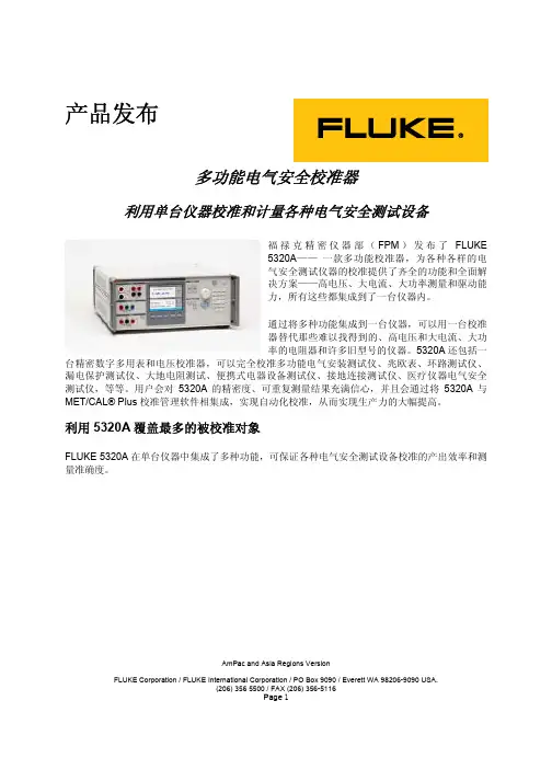
AmPac and Asia Regions VersionFLUKE Corporation / FLUKE International Corporation / PO Box 9090 / Everett WA 98206-9090 USA.(206) 356 5500 / FAX (206) 356-5116Page 1产品发布多功能电气安全校准器利用单台仪器校准和计量各种电气安全测试设备福禄克精密仪器部(FPM )发布了FLUKE5320A —— 一款多功能校准器,为各种各样的电气安全测试仪器的校准提供了齐全的功能和全面解决方案——高电压、大电流、大功率测量和驱动能力,所有这些都集成到了一台仪器内。
通过将多种功能集成到一台仪器,可以用一台校准器替代那些难以找得到的、高电压和大电流、大功率的电阻器和许多旧型号的仪器。
5320A 还包括一台精密数字多用表和电压校准器,可以完全校准多功能电气安装测试仪、兆欧表、环路测试仪、漏电保护测试仪、大地电阻测试、便携式电器设备测试仪、接地连接测试仪、医疗仪器电气安全测试仪,等等。
用户会对5320A 的精密度、可重复测量结果充满信心,并且会通过将5320A 与MET/CAL® Plus 校准管理软件相集成,实现自动化校准,从而实现生产力的大幅提高。
利用5320A 覆盖最多的被校准对象FLUKE 5320A 在单台仪器中集成了多种功能,可保证各种电气安全测试设备校准的产出效率和测量准确度。
谁是目标客户?主要的客户为直流/低频(DC/LF)校准实验室:第三方实验室内部校准实验室(公用事业部门、电信、电气制造厂商)部队/政府电气安全测试仪器制造商5320A的自动测试功能使其非常适合于生产测试和用于校准实验室。
被校准对象是什么?随着全球范围内电气安全标准的日益增多(包括英国的第16版测试标准和德国的VDE 0100及0700标准),电气安装和电器设备的测试成为电工和测试人员从事越来越多的常见任务。
Application NoteBecause pressure is one of the more widely measured param-eters in process industries, it is a critical function of a document-ing process calibrator. Fluke’s pressure modules cover a wide range of pressures and maintain accuracy over a wide tempera-ture range, from 0°C to 50°C (32° F to 122°F). The pressure measurement portion of the Fluke 700 Series Documenting Process Calibrators is separate from the main unit to facilitate connection to fixed or bulky equipment and to provide mul-tiple pressure ranges for a single calibrator.A large selection of gage and differential modulesA family of 27 pressure modules covers the most common pres-sure calibrations from 0-10" H2O (0-2.5 kPa) to 0-10,000 psi(0-70,000 kPa).Gage pressure modules have one pressure fitting and measure the process pressure with re-spect to atmospheric pressure. Differential pressure modules have two pressure fittings and measure the difference between the applied pressure on the high fitting versus the low fitting. Each module is clearly labeled for range, overpressure specifi-cation, and materials compatibil-ity. A metric adapter is included with all but the P29 through P31 high pressure modules. Figure 1 shows the two types.Quick and easy measurements Fluke 700 Series pressure mod-ules are easy to operate. To measure pressure, the technician disconnects the pressure mea-suring transmitter from the process, plumbs the pressure module to a pressure source, and connects the pressure module cable to the calibrator. Pressure is applied, measured by the pres-sure module, and displayed digi-tally on the calibrator. At thetouch of a button, the pressuremay be displayed in any of 10different pressure units. Becausethe 700 Series calibrators cancapture readings electronically,there’s no need to write downresults. The calibrators automati-cally time-stamp and store allsaved measurements, savingtime, and eliminating errors asso-ciated with making manual nota-tions in the field. These self-documenting capabilities areimportant in ensuring accuratemaintenance. They are also veryhelpful in collecting calibrationdata to support compliance withdocumentation standards, includ-ing those established by OSHA,the FDA, the EPA, and ISO 9000.Pressure module performanceFluke 700 Series pressure mod-ules are highly accurate, withsimply stated specifications thatapply from 0% to 100% of fullspan and from 0°C to 50°C (32°Fto 122°F)—a factor that sets themapart from other pressure calibra-tors. Most ranges have total un-certainties of 0.05% of full scale(see Table 1, page 2).This performance is possiblethrough the innovative applica-tion of mathematics and micro-processor power. Fluke pressuremodules have silicon piezo-resistor sensors which consist ofa resistive bridge fabricated in asilicon diaphragm. Pressure ap-plied to the diaphragm causes achange in the balance of thebridge which is proportional tothe applied pressure. The bridgebalance change is not linear andis very sensitive to temperature.However, since these effects arequite stable with time andthrough repetitive changes ofcondition, the sensors can bevery accurate in measuring pres-sure over a wide temperaturerange, provided they are care-fully characterized.During manufacture, Flukepressure modules are character-ized by reading temperature andpressure at more than 100points. A least-squares regres-sion is used to calculate the coef-ficients of polynomial expressionfor pressure. The coefficients,unique to that pressure module,are stored in the module’smemory.Fluke 700 Series Pressure ModulesFigure 1. Gage and Differential pressure modulesEach module has its own microprocessor, allowing it to run the measurement circuitry and to communicate digitally with the calibrator. When con-nected to the calibrator, the coef-ficients are uploaded from the pressure module to the calibrator.Then, when pressure measure-ments are made, raw sensor values for pressure and tempera-ture are digitally loaded to the calibrator, where the raw sensor values and coefficients are manipulated to derive and dis-play the pressure reading. This innovative technique provides several benefits:1.Digital communication elimi-nates errors due to poor connections and electrical interference.2.The modules are inherently temperature-compensated from 0°C to 50°C (32°F to 122°F), with no derating for temperature effects.Figure 2. 700 Series Pressure Modules are overmolded with protective urethane and sealedagainst dirt, dust and moisture. All fittings are made of 316 stainless steel or Hastelloy C276and have internal mechanical supports3.The modules are fully inter-changeable because all signal processing is handled in the pressure module itself and then communicated to the calibrator in digitized form.Modules are calibrated inde-pendently of the calibrator,and can be used with any 700Series calibrator. Each module has its own serial number to facilitate traceability.Sensor protection in isolated modules Many of these modules (see Table 1) incorporate a stainless steel diaphragm to isolate the sensor.With these modules, any medium that is compatible with stainless steel can be used on the high side of the module.Rugged construction The pressure modules are de-signed to operate accurately and reliably despite the rough han-dling and harsh environmental conditions often found in process plants. A urethane overmolding protects against shock if a mod-ule is accidentally dropped and also seals against dirt, dust, and moisture. The module case is held together with screws con-nected to brass-reinforced seats,and all the pressure fittings,which are constructed of 316stainless steel, have internal mechanical supports. Pressure connections are 1/4" NPT. A BSP/ISO adapter is also provided on all but the P29, P30 and P31.Small and lightweight Since process technicians might need to carry two or more pres-sure modules along with the calibrator, the modules are small and lightweight.Remote sensor A one-meter cable between the pressure module and calibrator reduces the length of connecting tubing to the pressure source.The remote pressure head also provides an extra margin of safety and convenience by re-moving the calibrator and opera-tor from the pressure source.Table 1. Pressure specifications1Total uncertainty, % of full span for temperature range 0°C to +50°C, one year interval. Total uncertainty, 1.0% of full span for temperature range -10°C to 0°C, one year interval.2“Dry” indicates dry air or non-corrosive gas as compatible media. “316 SS” indicates media compatible with Type 316 Stainless Steel.“C276” indicates media compatible with Hastelloy C276.Use of pressure zero is required prior to measurement or source.Pressure units available are: psi, kPa, bar, in. Hg, mm Hg, in. H 2O (@4°C), ft. H 2O (@4°C), kg/cm 2, in. H 2O (@60°F), mm. H 2O (@4°C).Maximum overpressure specification includes common mode pressure.Modules are rated.Metric adapter(s): 1/4" NPT female to male BSP/ISO 1/4-19, tapered thread, included with all modules except P29, P30, and P31.Effective October 1996, all modules include a NIST traceable certificate and test data.Notes for 701 and 702 users only: Internal software V1.3 or later required. kg/cm 2, in. H 2O (@60°F), mm H 2O units not available.Not compatible with the PA and PV modules. Resolution in inches H 2O and kPa may vary from that shown in table.Documentation of results The scheduling of calibration, creation of procedures and documentation of your calibration results are facilitated by a number of instrumentation management software packages:•Fluke DPC/TRACK ™•™ InstruMint and DocuMint••T erminologyAbsolute pressure—absolute pressure measurements are referenced to zero pressure,(a perfect vacuum.)Absolute pressure transducer—a transducer that has an internal reference chamber sealed at or close to zero pressure (full vacuum) when exposed to atmospherea reading of approximately14.7 psi results.Boyle’s Law—the volume of a gas is inversely proportional to the pressure of the gas at con-stant temperature: V=1/P. Common mode pressure—the underlying common pressure (or static pressure) within a sys-tem from which a differential measurement is being made.D/P: Differential pressure, (pronounced DP)—other names used to mean the same thing are d/p cell, d/p transmitter and ∆P transmitter (where ∆ is delta or differential). This is the most common type of transmitter used in most process industries. It can be used to measure level, flow, pressure, differential pressure, and density or specific gravity. With some modifications, it can measure such things as tem-perature and oxygen purity. The d/p transmitter can be pneu-matic, electromechanical, or solid state. It can also be a smart transmitter. A typical large pro-cess plant can have hundreds or thousands of d/p transmitters in service.PSI—pounds per square inch(same as psig).PSIA—pounds per square inchabsolute.PSID—pounds per square inchdifferential.PSIG—pounds per square inchgage (same as psi).Square root extractor—aninstrument or software programthat takes the square root ofinput and puts the result on itsoutput. Square root extraction isneeded to linearize many flowsignals. Example: orifice plates,venturis, target flow meters, andpitot tubes all require thetransmitter’s output signal to belinearized. Mag flow meters,turbine flow meters, Dopplerflow meters, and vortex shed-ding flow meters don’t requiresquare root extraction.Static pressure—the zero-veloc-ity pressure at any arbitrarypoint within a system.Wet/dry differential—a differ-ential pressure transducer ortransmitter that uses a metaldiaphragm at the wet portwhere fluids can be applied, andno diaphragm at the dry port.The dry port exposes the sensormaterial to the medium, so onlyclean dry gas can be applied tothis port.Wetted parts—the diaphragmand pressure port material thatcomes in direct contact with themedium (gas, liquid).Gage pressure—the pressurerelative to atmospheric pressure.Gage pressure = absolute pres-sure minus one atmosphere.Gage pressure transducer—a transducer that measures pres-sure relative to atmosphericpressure.Ideal Gas Law—combiningBoyle’s Law and Charles’ Law,results in the Ideal Gas Law:PV=nrT, where nr is constant fora particular gas analogous to thenumber of molecules and therelative size of the molecule.I/P (I to P)—a current to pres-sure transmitter. A common in-strument in modern industrialplants. A typical large paper millor refinery could have 5,000 I/Psin use.Line pressure—the maximumpressure in the pressure vesselor pipe for differential pressuremeasurement.Orifice plate—a very low costand common primary sensingelement (PSE) for measuringflow. It must be used in conjunc-tion with a d/p cell. It creates aventuri and a resulting P isdeveloped across the platewhose square root is propor-tional to flow.P/I (P to I)—a pressure to cur-rent transducer.Pneumatic relay—refers to apneumatic instrument that per-forms a function to its input andprovides the result on its output(Example: square root extractor,adder, etc.).Fluke-700 PCK Calibration KitThe Fluke 700PCK Pressure Cali-bration Kit makes it possible to calibrate your pressure modules at your facility using your own precision pressure standards.The kit consists of a power sup-ply, an interface adapter, appro-priate cables, and Fluke 700PC Pressure Module Calibration soft-ware. When installed on your PC,the Windows ®-based software easily steps you through an as-found verification, a calibration adjustment, and an as-left verifi-cation. Calibration data is cap-tured for import to your database.A 386 or better PC, running Windows 3.1, is required, along with a precision pressure stan-dard with an uncertainty of less than 1/4 that of the pressure mod-ule being verified.Fluke Corporation PO Box 9090, Everett, WA USA 98206Fluke Europe B.V.PO Box 1186, 5602 BDEindhoven, The NetherlandsFor more information call:U.S.A. (800) 443-5853 orFax (425) 356-5116Europe/M-East (31 40) 2 678 200 or Fax (31 40) 2 678 222Canada (905) 890-7600 orFax (905) 890-6866Other countries (425) 356-5500©1998 Fluke Corporation. All rights reserved.Printed in U.S.A. 1/98 B0300UEN Rev C Printed on recycled paper.Figure 8. Calibration kit configuration.Fluke-700 PMP Pressure PumpThis hand operated pressure pump can provide pressures up to approximately 150 psi (1000 kPa)for calibration and troubleshoot-ing of pressure instrumentation.Figure 9. Pressure pump Fluke.Keeping your world up and running.。
![fluke说明书[1]](https://uimg.taocdn.com/7b07d69151e79b896802267c.webp)
福禄克F430系列三相电能质量分析仪更快、更安全、更详细地定位和诊断的电能质量故障技术参数福禄克公司的F434 和F433三相电能质量分析仪可以帮助用户定位、预测、防止和诊断配电系统的故障。
对于那些维护或排障三相配电系统的工作人员来说,这些简便易用的手持工具是“必不可少”的。
新的IEC和GB国标关于闪变和电能质量方面的标准使得在对系统进行电能质量分析监测时有了判断的依据。
●记录三相系统中所有电能质量的参数。
●直观的菜单,最大程度上减少所需的设置。
●工业现场使用最高的安全等级。
●四个电压通道和四个电流通道。
●同时在所有相线上捕获波形数据。
●系统监测:在一个仪表板上现实全部电能质量参数。
●自动显示瞬态尖峰脉冲信号:不会漏掉任何一个事件。
●自动趋势绘图(AutoTrend)功能:无需对记录进行设置!●坚固的手持式设计。
●使用镍氢(NiMH)电池组时,一次充电可使用7个小时。
●将数据文件传输到PC,用于编写报告和利用FlukeView®软件进行分析。
CAT IV 600 V 和CAT III 1000 V的安全等级在设计时就考虑了保护用户和设备免受高压电击,福禄克F430系列电能质量分析仪、附件和充电器都经过验证,满足CAT IV 600 V和CAT III 1000 V环境下使用的严格的安全标准。
它们是同类别中第一款符合CAT IV安全等级的工具,所以可以被用于低压配电系统中所有的电气连接和插座。
快捷地观察趋势图利用AutoTrend(自动趋势绘图)功能,可以快速地深入浏览电能质量参数随时间的变化。
所显示的每一读数都被自动并且连续的进行记录,而不必设置触发限值或间隔时间,也无需手动启动记录过程。
可以快速地观察所有相线和零线上电压、电流、频率、功率、谐波或闪变的趋势图;还可以使用光标和缩放功能分析趋势-而不会中断记录。
AutoTrend功能在后台自动记录显示的所有参数。
在数据和趋势图之间切换,以及使用光标和缩放功能分析测量结果,都不会中断记录过程。

福禄克FLUKE过程校准仪中文说明书一,测量和信号输出功能一览表热电阻2,3,4线测量2线输出100ΩPlatinum(3926)100ΩPlatinum(385)120ΩNickel(672)200ΩPlatinum(385)500ΩPlatinum(385)1000ΩPlatinum(385)10ΩCopper(427)100ΩPlatinum(3916)压力27种压力模块从2.5kPa至69,000kPa *回路电压24或28V(22mA最大)*对于压力输出功能,是指由外部手动压力泵或其它压力源作为压力信号二、初识校准仪1.当你第一次取出校准仪,你需要将电池充电见图9,给电池充电2小时。
2.将电池放入校准仪中。
3.连接校准仪的电压输出端和输入端如下:连接最左端的一对插孔(V、Ω、RTD输出)和最右端的一对插孔(VMEAS)(见图3)。
图3 跨接线连接图4 输入输出的例子4.开机按⊙,按▲,▼以调整对比度。
以达到最好的显示效果。
校准仪在接通电源时是直流电压的测量功能,可以在一对VMEAS输入插孔中得到读数。
5.按看到其测量情况。
6.按V—…键,选择直流电压输出。
按数字键5和ENTER=开始输出5.0000V直流电压。
7.量直流电压。
你将在上半部屏幕看到测量读数,在下半部屏幕看到输出值,如图4所示。
三、操作功能1.输入和输出插孔图5所示,校准器输入和输出插孔,表2解释它的用途。
表2 输入/输出插孔和连接器7,8!SOURCE(输出)mA测量mAΩRTD插孔输出或测量电流、电阻和RTDS插孔,并提供回路电源9,10!SOURE(输出)V ΩRTD插孔输出电压、电阻、频率、和模拟RTDS输出插孔图5 输入/输出插孔和连接2.按键校准仪按键如图6所示,表3解释它们的功能,有4个未带标记的兰色按键,在显示屏幕下面称之为功能键。
其功能在操作过程中屏幕出现的定义所确定。
功能键和其显示内部在本手册中用黑体字标明,例如:Choices图6 按键表3 键的功能序号性能说明15 V-键测量方式中选择直流电压,输出方式中选择直流电压16 开关键电源开关3.显示屏幕图7为典型的显示屏幕。
®715Volt/mA Calibrator说明书 简介Fluke 715伏特/毫安校准仪 (Volt/mA Calibrator) 是一个伏特/毫安源及测量工具,用于 0到 24毫安的电流回路和 0到 20/25 V的直流电压测试上。
本校准仪不能同时用作输出和测量上。
您的校准仪应包括以下附件:皮套、一对测试导线、已经安装的9 V碱电池、以及本说明书。
校准仪功能摘要功能量程分辨率直流毫伏输入0 到 200 mV 0.01 mV直流毫伏输出到 25 V直流电压输入 00.001 V直流电压输出0 到 20 V直流毫安输入0 到 24 mA 0.001 mA直流毫安输出回路电源输出24 V dc 输出不适用PN 650314 (Simplified Chinese) July 1997 Rev. 3, 8/051997-2005 Fluke Corporation. All rights reserved. Printed in U.S.A.All product names are trademarks of their respective companies.若校准仪有损坏或缺少某些附件,请立即与采购的地方联系。
有关附件的资料,请和您的Fluke经销商联系。
欲订购零件或备件,请参阅“更换零件”。
要和Fluke 联系,请打电话:美国和加拿大:1-888-99-FLUKE (1-888-993-5853)欧洲:+31 402-675-200日本:+81-3-3434-0181新加坡:+65-*-276-6196世界其它地方:+1-425-356-5500通讯地址:Fluke Corporation Fluke Europe B.V.P.O. Box 9090, P.O. Box 1186,Everett, WA 98206-9090 5602 BD EindhovenNetherlands(荷兰)U.S.A.(美国) The或向我们的全球网址查询,地址是:国际符号符号含义J接地I保险丝M电池W有关本项功能的资料,请参阅本说明书。
福禄克FLUKE过程校准仪中文说明书一,测量和信号输出功能一览表热电阻2,3,4线测量2线输出100ΩPlatinum(3926) 100ΩPlatinum(385) 120ΩNickel(672) 200ΩPlatinum(385) 500ΩPlatinum(385) 1000ΩPlatinum(385) 10ΩCopper(427) 100ΩPlatinum(3916)压力27种压力模块从2.5kPa至69,000kPa*回路电压24或28V(22mA最大)*对于压力输出功能,是指由外部手动压力泵或其它压力源作为压力信号二、初识校准仪1.当你第一次取出校准仪,你需要将电池充电见图9,给电池充电2小时。
2.将电池放入校准仪中。
3.连接校准仪的电压输出端和输入端如下:连接最左端的一对插孔(V、Ω、RTD输出)和最右端的一对插孔(VMEAS)(见图3)。
图3 跨接线连接图4 输入输出的例子4.开机按⊙,按▲,▼以调整对比度。
以达到最好的显示效果。
校准仪在接通电源时是直流电压的测量功能,可以在一对VMEAS输入插孔中得到读数。
5.按看到其测量情况。
6.按V—…键,选择直流电压输出。
按数字键5和ENTER=开始输出5.0000V直流电压。
7.量直流电压。
你将在上半部屏幕看到测量读数,在下半部屏幕看到输出值,如图4所示。
三、操作功能1.输入和输出插孔图5所示,校准器输入和输出插孔,表2解释它的用途。
表2 输入/输出插孔和连接器7,8!SOURCE(输出)mA测量mAΩRTD插孔输出或测量电流、电阻和RTDS插孔,并提供回路电源9,10!SOURE(输出)V ΩRTD插孔输出电压、电阻、频率、和模拟RTDS输出插孔图5 输入/输出插孔和连接2.按键校准仪按键如图6所示,表3解释它们的功能,有4个未带标记的兰色按键,在显示屏幕下面称之为功能键。
其功能在操作过程中屏幕出现的定义所确定。
功能键和其显示内部在本手册中用黑体字标明,例如:Choices图6 按键表3 键的功能序号性能说明15V-键测量方式中选择直流电压,输出方式中选择直流电压16开关键电源开关3.显示屏幕图7为典型的显示屏幕。
河北钢铁集团永洋钢铁有限公司计量校准规范压力变送器Pressure Transmitter编制:杜延波审核:李春批准:赤荣编号:MMS/YG23 GC-012013年9月01 日发布2013年9 月10日实施河北钢铁集团永洋钢铁有限公司发布目录1. 范围 (2)2. 引用文献 (2)3. 概述 (2)4. 计量特性 (2)5. 校准条件 (5)6. 校准项目和校准方法 (8)7. 校准结果 (8)8. 复校时间间隔 (8)附录 A 压力变送器校验连接方式附录 B 压力变送器校准记录格式附录 C 压力变送器量值溯源图11 范围本规范适用于本公司压力(包括正、负表压力,差压和绝对压力)变送器的首次 校准、使用中的校准及修理后的校准。
2 引用文献JJG 882-2004 《压力变送器检定规程》 使用本规范时,应注意使用上述引用文献的现行有效版本。
3 概述压力变送器是一种将压力变量转换为可传送的标准化输出信号的仪表,而且其输出 信号与压力变量之间有一给定的连续函数关系(通常为线性函数)。
主要用于工业过程 压力参数的测量和控制,差压变送器常用于流量的测量。
压力变送器有电动和气动两大类。
电动的标准化输出信号主要为 0mA ~ 10mA 和 4mA ~ 20mA (或 1V ~ 5V )的直流电信号 。
气动的标准化输出信号主要为 20kPa ~ 100kPa 的气体压力。
不排除具有特殊规定的其它标准化输出信号。
压力变送器通常由两部分组成:感压单元、信号处理和转换单元。
有些变送器增加 了显示单元,有些还具有现场总线功能。
压力变送器的结构原理图如图 1 所示:图 1 压力变送器的结构原理框图压力变送器按原理可分为电容式、谐振式、压阻式、力(力矩)平衡式、电感式和 压变式等。
4 计量特性 4.1测量误差压力变送器的测量误差按准确度等级划分,应不超过表 1 的规定。
2现场总线输出信号(mA 、V 或kPa )压力变送器4.2 回差首次校准的压力变送器,其回差不应超过表 1 规定。