PowerFlex 40变频器用户手册
- 格式:pdf
- 大小:1.85 MB
- 文档页数:189


PowerFlex 中壓交流變頻器型號編號 6000G 、6000T 、7000A 、7000 與 7000LPowerFlex 中壓交流變頻器 產品選型指南內容主題頁碼最新消息2PowerFlex 中壓變頻器的優點3為您的應用選擇適合的 PowerFlex 變頻器4中壓變頻器選型流程圖6PowerFlex 中壓變頻器比較7一般應用負載扭矩系列9PowerFlex 6000T 中壓 交流變頻器11PowerFlex 7000 中壓交流變頻器15變頻器選項20其他資源23最新消息PowerFlex® 6000T 的增強功能包括:高速應用PowerFlex 6000T 可在所有控制模式下,以固有的方式控制高達 120 Hz 輸出頻率的高速應用。
已啟用 CIP SecurityPowerFlex 6000T 已啟用 CIP Security™,可支援深度防禦策略並保護⾃⾝不受所有網路資安事件影響。
擴充輸入電壓功能PowerFlex 6000T A 框架 IEC 變頻器的輸出電壓額定值為 3.3 和 4.16 kV,現在可提供高達 13.8 kV 的主要輸入功能。
選購的 RealSine 解決方案可用範圍 2.4…4.16 kV 且最高 215 A,無需變更變頻器專用變壓器的⼆次繞組數量,每個繞組經過特別的相位偏移分別可達到 54 脈衝或 72 脈衝,在這個電壓範圍下,其他傳統的設計只能達到 18 脈衝或 24 脈衝。
選購的 RealSine™ 解決方案在輸入總諧波電流失真 (THDi) 方面可改善高達 30%。
此新設計不需要額外的硬體,也不會影響變頻器的佔地面積。
減少佔地面積的 A 框架額定電壓為 6 與 6.6 kV 的 PowerFlex 6000T IEC 變頻器現在提供最高可達 215 A 的一體式設計。
這些小巧的變頻器可在不變更變頻器尺⼨下提供最高可達 13.8 kV 的一次側電壓。

ROCKWELL AUTOMATION PROCUREMENT SPECIFICATIONPROCUREMENT SPECIFICATIONPowerFlex 400Low Voltage ACVariable Frequency Drive with BypassNOTICE: The specification guidelines in this document are intended to aid in the specification of products. Specific installations have specific requirements, and Rockwell Automation does not recommend or intend any specific application based solely upon the guidelines provided here. Because of the variety of uses for this information, the user of, and those responsible for applying this information, are responsible for ensuring the acceptability of each application and appropriate use of the guidelines. In no event will Rockwell Automation be liable for misuse, misapplication or reliance on these guidelines in connection with any specific application. Rockwell Automation also disclaims indirect or consequential damages resulting from the use or application of this information.Note: To download or view a .doc file version of this procurement specification, please visit: /industries/procurement-specificationsTABLE OF CONTENTSPART 1 GENERAL (3)1.01 SUMMARY (3)1.02 RELATED SECTIONS (3)1.03 CERTIFICATIONS/REFERENCES (3)1.04 SUBMITTALS (3)1.05 CLOSEOUT SUBMITTALS (OPERATION AND MAINTENANCE MANUALS) (4)1.06 QUALITY ASSURANCE (4)1.07 DELIVERY, STORAGE AND HANDLING (5)1.08 WARRANTY (5)PART 2 PRODUCTS (5)2.01 MANUFACTURERS (5)2.02 RATINGS (5)2.03 CONSTRUCTION (6)2.04 BYPASS (7)2.05 CONFIGURATION/PROGRAMMING (8)2.06 COMMUNICATIONS (8)2.07 CONTROL FEATURES (8)2.08 CONTROL I/O (9)PART 3 EXECUTION (10)3.01 EXAMINATION (10)3.02 INSTALLATION (10)3.03 START-UP SERVICE (10)SECTION XX XX XXLOW VOLTAGE AC VARIABLE FREQUENCY DRIVE WITH BYPASSPART 1 GENERAL1.01 SUMMARYA. The Variable Frequency Drive (VFD) system shall contain all components required tomeet the performance, protection, safety and certification criteria of this specification.1.02 RELATED SECTIONSA. Section 26 05 00 – Common Work Results for ElectricalB. Section 26 00 00 – Electrical – General Provisions1.03 CERTIFICATIONS/REFERENCESA. Certifications and approvals shall include:1. c-UL-us – Listed to UL508C and CAN/CSA-C22.2 for Power Conversion Equipment2. C-Tick – AS/NZS, 1997 Group 1, Class A3. CE – Marked for all applicable European Directives:a) EMC Directive (2004/108/EC), Standards EN 61800-3, EN 50081-1,EN 50082-2b) Low Voltage Directive (73/23/EEC), Standards EN 50178, EN 60204B. The VFD shall also be designed to meet the appropriate portions of the followingspecifications:1. NFPA 70 – US National Electrical Code2. NEMA ICS3.1 – Safety Standards for Construction and Guide for Selection,Installation and Operation of Adjustable Speed Drive Systems3. IEC 146 – International Electrical CodeC. The VFD shall be listed to UL508C for mounting in plenums and compartments handlingconditioned air.D. The VFD shall meet the seismic requirements of the 2003 International Building Code asspecified by AC156.1.04 SUBMITTALSA. Submit under provisions of Section 01 30 00B. Shop Drawings – Approval1. Elevation Drawings: Shall include dimensional information and conduit routinglocations.2. Unit Descriptions: Shall include amperage ratings, enclosure ratings, fault ratings,nameplate information, etc. as required for approval.3. Wiring Diagrams:a) Power Diagram: Shall include amperage ratings, circuit breaker frame sizes,circuit breaker continuous amp ratings, etc. as required for approval.b) Control Diagram: Shall include disconnect devices, pilot devices, etc.4. Major components list.C. Product Data Sheets1. VFD publications.2. Data sheets and publications on all major components.D. Test procedures shall be per the manufacturer’s standards.1.05 CLOSEOUT SUBMITTALS (OPERATION AND MAINTENANCE MANUALS)A. Submit under provisions of Section 01 30 00B. Shop Drawings – Final as shipped1. Elevation Drawings: Shall include dimensional information and conduit routinglocations.2. Unit Descriptions: Shall include amperage ratings, enclosure ratings, fault ratings,nameplate information, etc. as required for approval.3. Wiring Diagrams:a) Power Diagram: Shall include amperage ratings, circuit breaker frame sizes,circuit breaker continuous amp ratings, etc. as required for approval.b) Control Diagram: Shall include disconnect devices, pilot devices, etc.4. Major components list.C. Product Data Sheets1. VFD publications.2. Data sheets and publications on all major components.D. Test procedures shall be per the manufacturer’s standards.E. Operation and Maintenance Data1. Service and Contact information.2. VFD User Manual.3. Troubleshooting/Service Manual.1.06 QUALITY ASSURANCEA. Qualifications:1. Manufacturers:a) The VFD and all associated optional equipment shall be UL listed orrecognized.b) The VFD shall contain a UL label attached on the inside of the enclosurecabinet.2. Suppliers:a) All inspection and testing procedures shall be developed and controlled underthe guidelines of the supplier’s quality system and must be registered toISO 9001 and regularly reviewed and audited by a third party registrar.b) The VFD shall be factory pre-wired, assembled and tested as a completepackage.1.07 DELIVERY, STORAGE AND HANDLINGA. Supplier shall coordinate the shipping of equipment with the manufacturer.B. Supplier shall store the equipment in a clean and dry space at an ambient temperaturerange of:1. 2.2 to 7.5 kW (3.0 to 10 HP), -40°C to 85°C (-40°F to 185°F).2. 11 to 250 kW (15 to 350 HP), -40°C to 70°C (-40°F to 158°F).C. The supplier shall protect the units from dirt, water, construction debris and traffic.1.08 WARRANTYA. The manufacturer shall provide their standard parts warranty for eighteen (18) monthsfrom the date of shipment or twelve (12) months from the date of being energized,whichever occurs first.B. This warranty applies to variable frequency drive systems.PART 2 PRODUCTS2.01 MANUFACTURERSA. Allen-Bradley – PowerFlex 400 Low Voltage AC Variable Frequency Drive with BypassPackage (No substitutions)2.02 RATINGSA. The variable frequency drive (VFD) shall be designed to operate in one of the followinginput voltage classes with ±10% voltage tolerance:1. 208 VAC, 3 phase.2. 460 VAC, 3 phase.B. The VFD shall have an AC frequency rating of 60 Hz ±5%.C. The VFD shall have a power rating of:1. 208 VAC:2.2 to 37 kW /3.0 to 50 HP.2. 460 VAC:a) Type 1 – 2.2 to 250 kW / 3.0 to 350 HP.b) Types 12, 3R, 4 – 2.2 to 110 kW / 3.0 to 150 HP.D. The displacement power factor of the VFD shall be 0.98 across the entire speed range.E. The efficiency of the VFD shall be 97.5% at rated amps, nominal line voltage.F. The overload capability shall be 110% for up to 1 minute.G. The VFD shall have a programmable output frequency range of 0 to 320 Hz.H. The VFD shall be designed to operate in the following environmental conditions:1. Ambient temperature range (without derating) shall be -10°C to 40°C (14°F to104°F).2. Relative humidity range – 0% to 95% non-condensing.3. Elevation – up to 1000 m (3280 ft.).4. Shock and vibration –a) Shock: 15G peak for 11 ms duration (±1.0 ms).b) Vibration: 1G peak, 5 to 2000 Hz.2.03 CONSTRUCTIONA. The variable frequency drive (VFD) shall have a compact footprint and be optimized for avariable torque application.B. The VFD shall be enclosed in a Type 1, 12, 3R or 4 enclosure with knockouts for bottomcable entry.C. The VFD with bypass package shall be wall-mountable.D. The VFD shall be protected:1. Against short circuits, between output phases and to ground.2. Against undervoltage and overvoltage.E. The VFD shall have an IGBT transistor.F. The VFD shall have an external EMC option to comply to IEC 61800-3 specification.G. The VFD shall have an RS-485 (DSI) port for connecting a single peripheral device or forsupporting standard communications protocol. A splitter shall be available for connectinga second peripheral device.H. The VFD shall have embedded control I/O.I. The VFD shall have an integral keypad for display, alarm indication, control andprogramming.1. The terminal shall include a 2-line by 16-character LCD display with LED backlightand be capable of showing parameters and faults in multiple languages viaselectable mode, including English, German, French, Italian, Spanish, Portugueseand Dutch.2. Control keys shall include HAND, AUTO and OFF.3. Digital speed control keys and programming navigation keys shall be provided.4. The terminal shall include LED indicators for program status, fault status and statusof the control keys.J. The VFD shall have optional Type 4X remote and Type 1 handheld keypads available.K. The VFD shall have a cooling fan.2.04 BYPASSA. Construction:1. The door-interlocked main input disconnect shall mount within the enclosure forpositive power disconnect of the VFD. It shall have the capability for door padlockingand be one of the following types:a) Disconnect switch with Class J fuses: Input line fuses shall provide protectionfor the input rectification circuit. The series interrupting rating of the VFD andfuses shall be a minimum of 100,000 AIC.b) Thermal magnetic molded case circuit breaker.2. A complete three-contactor bypass shall be provided to allow the motor to be safelytransferred from VFD output to the AC line or from the AC line to the VFD, while themotor is at zero speed. The contactor bypass shall be electrically interlocked. Thecontactors shall be IEC rated and have the following functionality:a) Drive input contactor shall open and close input to the VFD.b) Drive output contactor shall open and close the connection between the VFDand motor.c) Bypass contactor shall open and close the connection to line start the motor.3. Bypass motor overload protection shall be provided by bimetallic Class 20 overloadrelay.B. Operator Interface:1. A three-position DRIVE/DRIVE TEST/BYPASS switch on the bypass operatorinterface shall have the following functionality:a) In Drive Mode, the drive input contactor and the drive output contactor shall beclosed to allow operation of the motor by the drive.b) In Drive Test Mode, the drive input contactor shall be closed to keep the powerto the drive on. The drive output contactor and bypass contactor shall remainopen. This shall enable the user to test the drive before running the motor. Ajumper shall be added to test the drive while the motor is running in bypass andmust be field-installed to alert operators of this condition.c) In Bypass Mode, the drive input and the drive output contactor will be open toisolate the drive. The bypass contactor will be closed to allow the motor to rundirectly from the AC line.2. A three-position HAND/OFF/AUTO switch on the bypass operator interface shallallow the user to:a) Transfer the control source (Start/Stop) to the drive keypad in Hand Mode.b) Stop the motor in Off Mode.c) Transfer the control source (Start/Stop) to the drive’s terminal block in AutoMode.3. The bypass operator interface shall have the following indicating LEDs:a) Ready (green)b) Interlock Open (yellow)c) Bypass Run (green)d) Bypass Trip (red)e) Purge (yellow)f) Drive Output Enable (green)2.05 CONFIGURATION/PROGRAMMINGA. The variable frequency drive (VFD) shall be configurable through its integral RS-485communications using:1. PC2. Multi-drop networkB. The VFD shall be compatible with software:1. Connected Components WorkBench™ – This software offers controllerprogramming, device configuration and integration with HMI editor.2. DriveTools™ SP – This software can be used to program, monitor and control theVFD.2.06 COMMUNICATIONSA. The variable frequency drive (VFD) shall have integral RS-485 communications and shallsupport DSI.B. The following protocols shall be embedded in the VFD and selectable via a parameterwithout any field programming to download software prior to operation:1. Modbus RTU2. Metasys N23. P1-Plant Floor NetworkC. Optional adapters for EtherNet/IP, DeviceNet, ControlNet, LonWorks, BACnet,PROFIBUS DP and Bluetooth shall be available.2.07 CONTROL FEATURESA. The variable frequency drive (VFD) shall operate via Volts per Hertz control.B. The VFD’s internal adjustments shall include:1. Acceleration time 0.1 to 600 seconds.2. Deceleration time 0.1 to 600 seconds.3. 4 preset speeds.4. PWM frequency, allowing tuning to the motor.C. The VFD’s protections shall include:1. Ability to sense a loss of load and signal a fault.2. Ability to issue a warning if the input analog reference is lost, with a programmableresponse:a) Stop and display the fault.b) Run at a preset speed.c) Run at minimum or maximum frequency.3. Ability, upon VFD fault, to store the DC bus voltage, out current and outputfrequency in readable parameters.D. The VFD’s control features shall include:1. Process PID control:a) The VFD’s PID regulator shall allow a pressure or flow signal to be connectedfor closed loop control.b) The PID set point shall be adjustable from the terminal, by analog input orthrough communication network.2. Skip frequencies/bands:a) The VFD shall have at minimum 3 programmable set points that lock outcontinuous operation at frequencies (mechanical resonance).b) The set points shall have adjustable bandwidth.3. Flying start – The VFD shall be capable of determining the speed and direction of aspinning motor, allowing its output to “pick-up” a rotating motor.4. Start at power-up – With a maintained 2-wire start input, the VFD shall be able touse its programmable restart function to automatically restore power after anoutage.5. Sleep/wake mode:a) The VFD shall be able to cycle off for low demand (sleep) and automaticallyrestart for increased demand (wake).b) Sleep/wake time and level shall be programmable.6. Auto restart – The VFD shall have the ability to attempt 9 automatic restarts atprogrammable intervals following a fault before locking out and requiring manualintervention.2.08 CONTROL I/OA. The variable frequency drive (VFD) shall have 1 optically isolated analog input (-10 to10V or 0 to 20 mA), user selectable, and 1 non-isolated analog input (0 to 10V or 0 to20 mA), user selectable.1. Analog inputs shall have 10 bit resolution or better.2. Both analog inputs shall be able to be used simultaneously in either voltage orcurrent modes or a combination of each.B. The VFD shall have 2 analog outputs (0 to 10V or 0 to 20 mA), user selectable.1. Analog outputs shall have 10 bit resolution or better.2. Both analog outputs shall be able to be used simultaneously in either voltage orcurrent modes or a combination of each.C. The VFD shall have 7 digital inputs (24 VDC), user programmable.1. Inputs shall be configurable as sink or source.2. The VFD shall have 1 dedicated digital input for a purge function. The purge inputshall override all “Stop” commands over the network as well as 1 customer interlock.3. The VFD shall have 2 dedicated digital inputs for customer interlocks:a) One interlock records a fault and permits running after external condition is met.Purge input will override this interlock.b) One interlock causes a drive fault and requires control system to reset prior toreturning to ready condition. This input will always be active even during purge.D. The VFD shall have 2 relay outputs, form C (1 N.O. and 1 N.C.), user programmable.1. Both relays shall be programmable for a minimum of 16 different combinationsincluding Drive Ready, At Frequency, Motor Running, Motor Overload, AboveFrequency, Above Current and others.E. The VFD shall have 1 digital optocoupler output, user programmable with N.O. or N.C.configuration.1. The digital optocoupler output shall be programmable for a minimum of 16 differentcombinations including Drive Ready, At Frequency, Motor Running, Motor Overload,Above Frequency, Above Current and others.F. The VFD shall have available 6 relay outputs, form A, user programmable, via userinstalled auxiliary relay board (Frame D through H option).PART 3 EXECUTION3.01 EXAMINATIONA. Verify that location is ready to receive equipment.B. Verify that the building environment can be maintained within the service conditionsrequired by the manufacturer of the VFD.3.02 INSTALLATIONA. Installation shall be in compliance with all manufacturer requirements, instructions anddrawings.3.03 START-UP SERVICEA. At a minimum, the start-up service shall include:1. Perform pre-power check2. Megger motor resistances: phase-to-phase and phase-to-ground3. Verify system grounding per manufacturer’s specifications4. Verify power and signal grounds5. Check connections6. Check environment[PROJECT NUMBER] [PROJECT NAME][DATE] [PROJECT LOCATION]PowerFlex 400 Low Voltage AC VFD with BypassRockwell Automation 23C-SR001D-EN-P 11 B. Drive power-up and commissioning:1.Measure incoming power phase-to-phase and phase-to-ground 2.Measure DC bus voltage 3.Measure AC current unloaded and loaded 4. Measure output voltage phase-to-phase and phase-to-ground5. Verify input reference signalC. All measurements shall be recorded.D. Drive shall be tuned for system operation.E. Drive parameter listing shall be provided.END OF SECTION。


搭载 TotalFORCE 控制技术的 PowerFlex 变频器固件版本 10.xxx本产品的参数及故障和报警代码参⻅此 PDF 文件随附的电子表格。
如需访问这些电子表格,保存此 PDF 文件并在您的设备上(而非浏览器)打开。
然后,单击此处打开“附件”窗格(⻅左侧)即可访问每个电子表格。
2罗克⻙尔⾃动化出版物 750-PM101A-ZH-P - 2021 年2 月搭载 TotalFORCE 控制技术的 PowerFlex 变频器 编程手册重要⽤⼾须知在安装、配置、操作或维护本产品之前,请阅读本文档以及“其他资源”章节所列的文档,了解关于安装、配置和操作该设备的信息。
除了所有适用的条例、法律和标准的要求之外,用⼾还必须熟悉安装和接线说明。
包括安装、调整、投⼊运⾏、使用、装配、拆卸和维护等在内操作必须由经过适当培训的人员根据适用的操作守则来执⾏。
如果未遵照制造商所指定的方式使用该设备,将可能导致该设备提供的保护失效。
任何情况下,对于因使用或操作本设备造成的任何间接或连带损失,罗克⻙尔⾃动化有限公司概不负责。
本手册中包含的示例和图表仅用于说明。
由于任何具体安装都涉及众多变数和要求,罗克⻙尔⾃动化有限公司对于依据这些示例和图表所进⾏的实际应用不承担任何责任和义务。
对于因使用本手册中所述信息、电路、设备或软件而引起的专利问题,罗克⻙尔⾃动化有限公司不承担任何责任。
未经罗克⻙尔⾃动化有限公司的书⾯许可,不得复制本手册的全部或部分内容。
在整本手册中,我们在必要的地方使用了以下注释,来提醒您留意安全注意事项。
标签也可能位于设备表⾯或内部,提供具体的预防措施。
警告:标识在危险环境下可能导致爆炸,进而导致人员伤亡、物品损坏或经济损失的操作或情况。
注意:标识可能导致人员伤亡、物品损坏或经济损失的操作或情况。
注意符号可帮助您确定危险情况,避免发生危险,并了解可能的后果。
重要信息标识对成功应用和了解本产品有重要作用的信息。
PowerFlex 40 Adjustable Frequency AC Drive PowerFlex 40变频器User Manual用户手册重要用户信息固态设备具有不同于电动机械设备的操作特性。
《固态控制器的应用、安装和维护安全指南》(出版号SG I-1.1,本资料可从当地的Rockwell销售办事处或/manuals/gi获得)说明了固态设备和硬接线电动机械设备之间的重要差别。
由于这些差别的存在以及固态设备应用的多样性,因此所有技术人员有责任确保这些固态设备的每项应用是可行的。
罗克韦尔自动化公司绝不承担因使用该设备而引起的间接或灾后损失的责任或义务。
本手册所包含的例子和图表仅仅用于说明。
因为任何特定安装有着特定的变化因素和需求,所以罗克韦尔自动化公司不承担用户基于例子和图表中实际应用的任何责任或义务。
关于本手册中所说明的信息、电路、设备或软件,罗克韦尔自动化公司不承担任何专利责任。
如果没有得到罗克韦尔自动化公司书面允许,严厉禁止任何团体、公司、个人对本手册的内容进行整体或部分复制。
我们使用了注释贯穿于本手册,提醒用户作安全考虑。
本手册系根据英文原文版翻译而成。
本手册中若有与英文不符之处,请以英文为准。
252627注意事项:是指有关导致人员伤亡、财产损害或经济损失的实际应用或环境情况。
注意事项可以帮助用户z识别危害z避免危害z认识危害所带来后果重要事项:是指用户对有关产品正确理解和应用所需掌握的重要信息。
DriveExploer,Drive tools32和SCANport是罗克韦尔自动化公司的商标。
PLC是罗克韦尔自动化公司的登记注册商标。
ControlNet是ControlNet国际有限公司的商标。
DeviceNet是Open DeviceNet Vendor Association的商标。
目录前言概述谁应该使用本用户手册… ……………. .P-1参考资料…………………………………………P-1手册定义 ……………………………………P-2变频器外形尺寸…………………………………P-2预防措施… …………………………………P-3产品目录号说明…………………………………P-4 第一章安装/接线打开面板………………………………………….1-1安装注意事项……………………………………1-2交流电源注意事项 ………………… 1-3接地要求…… ………………………………1-4熔断器和断路器…………………………………1-6电源接线…………………………………………1-8I/O接线 ……………………………………..1-12起动和速度给定控制………………………… 1-20EMC电磁兼容指南……………………………..1-22 第二章起动变频器启动前的准备工作 ……………………2-1操作面板 ……………………………………2-3参数浏览和编辑…………………………………2-4远程操作面板2-5 第三章编程与参数关于参数 ………………………………… 3-1参数构成…………………………………………3-2显示组……………………………………………3-3基本程序(设置)组 …………………… . 3-9高级程序(设置)组 …………………………… 3-14参数对照-按名称(英文字母)顺序…………… 3-42 第四章故障处理变频器状态………………………………………4-1故障情况……………………………………… 4-1故障说明…………………………………………4-3常见故障和处理措施……………………………4-5 附录A 变频器附加信息变频器、熔断器和断路器的额定值…………….A-1技术规范 ……………………………………… A-2 附录B 附件和尺寸产品选型………………………………………….B-1产品尺寸………………………………………… B-7 附录C RS485(DSI)协议附录D RJ45 DSI 分裂式电缆附录E 基本逻辑、步序逻辑和定时器/计数器功能附录F PID 设置索引前言概述本手册的目的是为用户提供PowerFlex40交流变频器的安装、起动和故障处理所需的基本信息。

Power Flex 使用手册1. 引言在现代社会,电力供应已成为我们生活中不可或缺的部分。
而 Power Flex 作为一种新型的电力调节设备,可以帮助我们更好地管理和利用电力资源。
本文将从使用方法、注意事项和个人观点等方面对 Power Flex 进行全面评估,并为您提供高质量的使用手册。
2. Power Flex 的使用方法Power Flex 针对电力调节进行了创新设计,使用方法相对简单。
您需要将电力设备与 Power Flex 连接,并按照说明书进行基础设置。
接下来,根据您的电力需求和使用习惯,调节 Power Flex 的功率和频率,以达到最佳的电力调节效果。
如果需要进一步了解 Power Flex 的高级功能和参数设置,建议您参考详细的操作手册或向专业人员沟通。
3. Power Flex 的注意事项在使用 Power Flex 的过程中,有一些注意事项需要特别注意。
务必确保电力设备和 Power Flex 的连接牢固可靠,以避免电力波动对设备造成损害。
在调节功率和频率时,需谨慎操作,避免超出设备的承载范围。
定期检查和维护 Power Flex,以确保其长期稳定工作。
遵循相关的安全操作规程,确保使用过程安全可靠。
4. 个人观点和理解在我看来,Power Flex 作为一种电力调节设备,为我们的生活带来了极大的便利。
通过灵活调节电力参数,我们能够更好地利用电力资源,降低能源消耗,实现节能减排的目标。
Power Flex 的智能化设计也为我们提供了极大的便利,使电力管理变得更加高效和智能。
相信随着科技的不断进步,Power Flex 将会在未来发挥越来越重要的作用。
5. 总结和回顾通过本文的详细介绍,相信您已经对 Power Flex 的使用方法、注意事项和个人观点有了全面的了解。
在今后的使用过程中,希望您能充分发挥 Power Flex 的优势,为我们的生活带来更多便利和效益。
6. 结语在使用 Power Flex 的过程中,不断深化对其功能和性能的理解,是我们提高电力管理水平的关键。
PowerFlex40 的EtherNet/IP 网络控制一、实验主题:创建一个ControlLogix 项目通过EtherNet/IP 控制PowerFlex40 变频器二、实验步骤:1. 变频器参数设置。
将带有22-COMM-E 适配器的PowerFlex40 变频器上电, 通过它的操作面板对其参数进行设置。
为实现网络控制, 将P36[Start Source]( 起动源) 设为5, 即选择Comm Port( 通讯端口给定); 将P38[Speed Reference]( 速度给定) 设为5, 即选择Comm Port( 通讯端口给定)。
2. RSLinx 通讯组态。
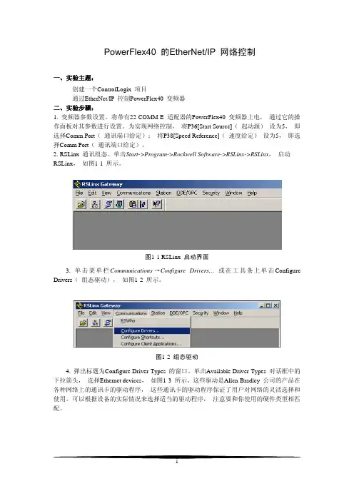
单击Start->Program->Rockwell Software->RSLinx->RSLinx, 启动RSLinx, 如图1-1 所示。
图1-1 RSLinx 启动界面3. 单击菜单栏Communications→Configure Drivers… 或在工具条上单击Configure Drivers( 组态驱动), 如图1-2 所示。
图1-2 组态驱动4. 弹出标题为Configure Driver Types 的窗口。
单击Available Driver Types 对话框中的下拉箭头, 选择Ethernet devices, 如图1-3 所示。
这些驱动是Allen-Bradley 公司的产品在各种网络上的通讯卡的驱动程序, 这些通讯卡的驱动程序保证了用户对网络的灵活选择和使用。
可以根据设备的实际情况来选择适当的驱动程序, 注意要和你使用的硬件类型相匹配。
图1-3 选择驱动组态类型5. 单击Add New 按钮, 将弹出如图1-4 所示窗口。
图1-4命名驱动6. 单击OK,会弹出如图1-5 所示窗口,按照指导说明在Station 的Host Name 中输入的IP 地址。
PowerFlex40 IP 地址:192.168.1.56;1756-ENBT IP 地址:192.168.1.57。
PowerFlex 40 Adjustable Frequency AC Drive PowerFlex 40变频器User Manual用户手册重要用户信息固态设备具有不同于电动机械设备的操作特性。
《固态控制器的应用、安装和维护安全指南》(出版号SG I-1.1,本资料可从当地的Rockwell销售办事处或/manuals/gi获得)说明了固态设备和硬接线电动机械设备之间的重要差别。
由于这些差别的存在以及固态设备应用的多样性,因此所有技术人员有责任确保这些固态设备的每项应用是可行的。
罗克韦尔自动化公司绝不承担因使用该设备而引起的间接或灾后损失的责任或义务。
本手册所包含的例子和图表仅仅用于说明。
因为任何特定安装有着特定的变化因素和需求,所以罗克韦尔自动化公司不承担用户基于例子和图表中实际应用的任何责任或义务。
关于本手册中所说明的信息、电路、设备或软件,罗克韦尔自动化公司不承担任何专利责任。
如果没有得到罗克韦尔自动化公司书面允许,严厉禁止任何团体、公司、个人对本手册的内容进行整体或部分复制。
我们使用了注释贯穿于本手册,提醒用户作安全考虑。
本手册系根据英文原文版翻译而成。
本手册中若有与英文不符之处,请以英文为准。
252627注意事项:是指有关导致人员伤亡、财产损害或经济损失的实际应用或环境情况。
注意事项可以帮助用户z识别危害z避免危害z认识危害所带来后果重要事项:是指用户对有关产品正确理解和应用所需掌握的重要信息。
DriveExploer,Drive tools32和SCANport是罗克韦尔自动化公司的商标。
PLC是罗克韦尔自动化公司的登记注册商标。
ControlNet是ControlNet国际有限公司的商标。
DeviceNet是Open DeviceNet Vendor Association的商标。
目录前言概述谁应该使用本用户手册… ……………. .P-1参考资料…………………………………………P-1手册定义 ……………………………………P-2变频器外形尺寸…………………………………P-2预防措施… …………………………………P-3产品目录号说明…………………………………P-4 第一章安装/接线打开面板………………………………………….1-1安装注意事项……………………………………1-2交流电源注意事项 ………………… 1-3接地要求…… ………………………………1-4熔断器和断路器…………………………………1-6电源接线…………………………………………1-8I/O接线 ……………………………………..1-12起动和速度给定控制………………………… 1-20EMC电磁兼容指南……………………………..1-22 第二章起动变频器启动前的准备工作 ……………………2-1操作面板 ……………………………………2-3参数浏览和编辑…………………………………2-4远程操作面板2-5 第三章编程与参数关于参数 ………………………………… 3-1参数构成…………………………………………3-2显示组……………………………………………3-3基本程序(设置)组 …………………… . 3-9高级程序(设置)组 …………………………… 3-14参数对照-按名称(英文字母)顺序…………… 3-42 第四章故障处理变频器状态………………………………………4-1故障情况……………………………………… 4-1故障说明…………………………………………4-3常见故障和处理措施……………………………4-5 附录A 变频器附加信息变频器、熔断器和断路器的额定值…………….A-1技术规范 ……………………………………… A-2 附录B 附件和尺寸产品选型………………………………………….B-1产品尺寸………………………………………… B-7 附录C RS485(DSI)协议附录D RJ45 DSI 分裂式电缆附录E 基本逻辑、步序逻辑和定时器/计数器功能附录F PID 设置索引前言概述本手册的目的是为用户提供PowerFlex40交流变频器的安装、起动和故障处理所需的基本信息。
PowerFlex 低壓變頻器性能強大。
靈活操控。
2Rockwell Automation 出版品 PFLEX-SG002P-ZC-P - 2022 年10 月PowerFlex 低壓變頻器產品選型指南內容最新消息擴大 TotalFORCE 技術的使用修訂版 11 韌體版本•支援氣冷式 PowerFlex® 755TS 變頻器-框架 1 7,400V/480V-預測維護有助於避免意外停機時間-支援 TotalFORCE® 電力供應選項卡,在三相電源斷電時保持控制和通訊作用-扭矩準確度模組 (框架 2...7) - 改善捲繞機、拆捲機與測試台等敏感應用的扭矩準確度-動態煞車功能 - 釋放過量的直流匯流排能量⽽不需將其送回主電源-額外的停止模式 - 用於在不將過多的再⽣能量送回直流匯流排時進⾏減速•支援250Hp 額定值的氣冷式框架6PowerFlex 755TL、755TM 與755TR •安全擦除有助於保護客戶的知識產權•用於進⾏ PowerFlex 755TL、755TM 與 755TR 變頻器故障檢測的電源轉入式故障與警示資訊參數PowerFlex 755TS 交流變頻器PowerFlex 755TS 變頻器是結合 TotalFORCE 技術的傳統六脈衝變頻器。
在此之前,TotalFORCE 僅能在採用主動式前端技術的 PowerFlex 755T 變頻器中使用,⽽現在應用範圍更加廣泛。
其中包括⾵扇、幫浦與輸送帶應用,以及更進階的馬達控制製程,⽽這些製程需要專用變頻器解決方案中常⾒的⾼效能功能。
PowerFlex 755TS 採用三種主要方式,為幾乎所有的馬達控制應用提供簡化且一致的使用者體驗:•彈性、⾼效能的控制•即時營運智慧與預測維護•在 Studio 5000® 設計環境中可輕鬆進⾏設定、整合和視覺化PowerFlex 755TM 變頻器的非再生電源在不需要再⽣與低諧波時,提供適合共用匯流排之節省空間、具成本效益的解決方案。
Installation Instructions PowerFlex ® DC Drive - Frame B Cooling Fan What This Kit Includes•Cooling fan •Fan cover plate •Two screws and washers •Fan terminal block and screw •Static strap Tools That You Need•Phillips ® screwdriver •Flathead screwdrivers Phillips ® is a registered trademark of Phillips Screw Company.What You Need to Do To install the cooling fan:❐ Step 1:Remove power from the drive❐ Step 2:Remove the existing cooling fan❐ Step 3:Install the new cooling fan❐ Step 4:Document the change!ATTENTION: Only qualified personnel familiar with DC drives and associated machinery should plan or implement the installation, start-up and subsequent maintenance of the system. Failure to comply may result in personal injury and/or equipment damage.!ATTENTION: To avoid an electric shock hazard, ensure that all power to the drive has been removed before performing the following.!ATTENTION: This drive contains ESD (Electrostatic Discharge) sensitive parts and assemblies. Static control precautions are required when installing, testing, servicing or repairing this assembly. Component damage may result if ESD control procedures are not followed. If you are not familiar with static control procedures, reference A-B publication 8000-4.5.2, “Guarding Against Electrostatic Damage” or any other applicable ESD protection handbook.2PowerFlex® DC Drive - Frame B Cooling FanStep 1:Remove Powerfrom the Drive1.Remove and lock-out all incoming power to the drive.Step 2:Remove the Existing Cooling Fan 1.Remove the two screws that secure the rear plastic shield to the bottomof the drive and remove the shield.!ATTENTION: Remove power before making or breaking cableconnections. When you remove or insert a cable connector withpower applied, an electrical arc may occur. An electrical arc cancause personal injury or property damage by:•sending an erroneous signal to your system’s field devices, causing unintended machine motion•causing an explosion in a hazardous environmentElectrical arcing causes excessive wear to contacts on both themodule and its mating connector. Worn contacts may createelectrical resistance.Remove screws and shieldBottom ViewPowerFlex® DC Drive - Frame B Cooling Fan3 2.Locate the cooling fan terminal block, between the fans, on the bottomof the drive and loosen the screws that secure the fan power supplywires (red and black) to the terminal block and remove the wires. Important:Note the color and location of each of the wires connected to the terminal block to ensure that each wire is properlyconnected during installation.ing a flathead screwdriver, carefully pry the cover plate off of the fanhousing.Remove fancover plate4PowerFlex® DC Drive - Frame B Cooling Fan4.Insert a Phillips® screwdriver through the mounting holes on the fanhousing, remove the two screws and washers that secure the fan to thedrive frame and remove the fan from the drive. Remove screwsand washers Insert screwdriverthrough hole in fanhousingPowerFlex® DC Drive - Frame B Cooling Fan5Step 3:Install the New Cooling Fan Install the new cooling fan in reverse order of removal as detailed in Step 2: Remove the Existing Cooling Fan on page2.•Inspect the fan connection terminal block for cracks, stripped screws, etc. If necessary, replace the terminal block with the new one provided with the kit.Important:Verify that the air flow direction arrow on the fan is pointed toward the top of the drive.Publication 20P-IN030A-EN-P - March 2009Copyright © 2009 Rockwell Automation. All rights reserved. Printed in USA.Step 4:Document theChange Record the installation of the new cooling fan and date of installation on the Field Installed Option label on the side of the drive (as shown below). Related Documentation Allen-Bradley publications are available on the internet at/literature .For . . .Read this document Publication Number In depth information regarding theoperation of PowerFlex Digital DC drives User Manual - PowerFlex Digital DC Drives 20P-UM001…。
WB-PowerFlex-SWattBox ™ PowerFlex™ Kit with Duplex 110V Wall Plate and Silicon A/V Pass ThroughThe WattBox ™ Powerflex™ kit offers the benefits of surge protection with the convenience of bulk wire management in one product. This product is designed for use with on-wall television installations.IMPORTANT SAFETY INSTRUCTIONS1. Read and understand all instructions. Follow WARNING and CAUTIONlabels on the product.2. Do not install the unit near water or where moisture is present.3. Use 12/2C or 14/2C Copper Utility [CU] wire only with this product. This product is rated to use with an existing A/C outlet 15-amp 125v grounded circuit only.4. For shock protection, do not install this product to a non-grounded outlet/ system. Use a 3-wire, grounded outlet only.EQUIPMENT REQUIREDBuilding electrical wire is not supplied; 12/2C or 14/2C IN-DOOR building electrical wire is recommended. Non-metallic or NM electrical wire (ex. ROMEX needs registered mark) can be purchased at home supply or hardware stores. Check local building codes for specific types of building wire requirements, such as MC, BX or AC type wire. ROMEX® is a Registered Trademark of Southwire Corporation.TOOLS REQUIREDStud Finder, Tape Measure, Pencil, Level, Drywall Saw or Sharp Utility Knife, Phillips Head and Flat Blade Screw Driver, Wire-stripper, Needle Nose Pliers, and Electrical Outlet TesterSTEP 3 – CONNECTING PowerFlex ™ INLET & OUTLET1. Plug “female” end of the Power Cord, into the “male” plug of the INLET.2. Plug “male” plug of the Power Cord into the existing A/C outlet or power surge protector. THE SYSTEM IS NOW POWERED. NOTE: If the supplied POWER CORD is not long enough, DO NOT EXTEND THE SUPPLIED CORD with another extension cord. Must use 3 prong-grounded, UL LISTED extension cord. DO NOT EXCEED 15 FEET IN LENGTH.3. Check for proper wiring connections with an outlet tester before plugging in any device to the product.CONNECTING ELECTRICIAL WIRE FOR OUTLET & INLET1. Strip ¼ inch off each of the three non-metallic wires and verify that ¼ inch is off the outlet plate.2. Using wire nuts (supplied), connect the three electrical wires (Green = Ground, Black = Live, White = Neutral).3. Push excess electrical wire back through the rear opening of the BLUE workbox and make sure to have the wire nuts all the way into the back.4. Place the outlet plate into the workbox and screw securely into place with the colormatched screws.LIFETIME LIMITED WARRANTYThis WattBox ™ product has a Lifetime Limited Warranty. This warranty includes parts and labor repairs on all components found to be defective in material or workmanship under normal conditions of use. This warranty shall not apply to prod-ucts which have been abused, modified or disassembled. Products to be repaired under this warranty must be returned toSnapAV or a designated service center with prior notification and an assigned return authorization number (RA)Tech Support: 1.866.838.5052ETL LISTED CONFORMS TO UL STD 498, UL STD 514D.CERTIFIED TO CSA C22.2 No.42, C22.2 No.42.1, C22.2 No.854120301-1152CONTENTS(2) Work Boxes(1) Recessed Male Inlet faceplate with screws (1) Duplex Outlet faceplate with screws (2) PowerFlex face plates (2) Flexnose(1) 36” 3-Prong Rower Cord (6) Wire Nuts(2) Hardware Kits with sheet rock anchors and screwsINSTALLATION INSTRUCTIONSBEFORE YOU START –1. Check with your local building jurisdiction as to permit, license or code requirements for installing wire or outlets within a wall. Some municipalities require an electrical inspection for modification of electrical work. We recommend all modifications or alterations of existing or new electrical work to be inspected by a licensed electricalinspector.2. This product is not to be installed, direct wired, connected or branched to the building electrical circuit/wiring system! Install this product ONLY as an electrical extension plug-in device to an existing A/C grounded outlet to energize A/C power using a UL listed plug-in cord set when installed with specific code compliant building electrical wire.3. Install this product to meet National Electrical Code and/or State and Local Building Code requirements for installing electrical building wire and outlets as a singleEXTENSION CIRCUIT, without modification or alteration to the building electricalcircuit/wiring system. Installation Code Compliancy is the responsibility of user and or installer, and not of the Manufacturer or its agents.4. Manufacturer is not liable for damages due to improper installation methods not followed herein or as required by national electrical or local building code. If you are not skilled with running wire through walls, it is strongly recommended that a qualifiedprofessional should install this product.5. This product does not have built-in electronic circuitry for surge protection or A/C filtering. It is recommended that this product be connected to a quality surge-protector/power conditioner for equipment protection.STEP 1 – DETERMINE BEST LOCATION• TELEVISION or PROJECTOR location ~ OUTLET Wall Plate (Female Receptacle) - Determine based on where the TV wall-mount will be installed, on which side (above or below the mount) will be best suited for the location of the TV power connection, and will not interfere with the TV installation on the mount. ~ Measure height and width of TV tokeep the wall plate hidden behind the TV.• SOURCE EQUIPMENT / Existing A/C outlet location ~ INLET Wall Plate (Male Plug) - Determine location on the wall near the source equipment or within 30 inches of an existing A/C outlet.1. Determine location on the wall/ceiling between framing studs using a stud finder. Note: The Powerflex ™ outlet and inlet plates can be installed either vertically or horizontally.2. Trace a cut line with the supplied “hole cut-out template” - on back of product box.3. Use a level for proper alignment.4. Cut on lines using a drywall saw or utility knife.23STEP 2 – INSTALL & ROUTE ELECTRICAL BUILDING WIRE & AV CABLE1. Route electrical building wire (not supplied) within wall and/or ceiling between the two cut-outs.2. Using a screwdriver, bend one tab OUT on the backside of the BLUE box, and insertelectrical wire. Leave approximately 4 inches sticking out from the edge of the box. 3. Strip off 3 inches of the outer sheath of the electrical wire. 4. Insert the BLUE box into the wall opening.5. Screw in the 2 silver screws to open the wall-wings to secure the boxes to the wallboard, and use a level for proper alignment.6. A lign the PowerFlex™ face plate over the recessed inlet or outlet face plate to determine the location of the AV cable hole and sheet rock anchor(s). Use a pencil or pen to outline the AV cable hole and location for the sheet rock anchor. Note: The rectangular face plate will need one sheet rock anchor, where the square face plate will need two sheet rock anchors.7. Drill the AV cable hole, install the sheet rock anchor(s), install the outlet / inlet face plate, and run the AV Cable in the wall. To properly install the electrical wire connection, see “CONNECTING ELECTRICAL WIRE FOR OUTLET & INLET”.8. I nstall the PowerFlex™ face plate by installing the screws to the workbox and Sheet rock anchor(s).PowerFlex-S。
PowerFlex 40 Adjustable Frequency AC Drive PowerFlex 40变频器
User Manual
用户手册
重要用户信息
固态设备具有不同于电动机械设备的操作特性。
《固态控制器的应用、安装和维护安全指南》(出版号SG I-1.1,本资料可从当地的Rockwell销售办事处或/manuals/gi获得)说明了固态设备和硬接线电动机械设备之间的重要差别。
由于这些差别的存在以及固态设备应用的多样性,因此所有技术人员有责任确保这些固态设备的每项应用是可行的。
罗克韦尔自动化公司绝不承担因使用该设备而引起的间接或灾后损失的责任或义务。
本手册所包含的例子和图表仅仅用于说明。
因为任何特定安装有着特定的变化因素和需求,所以罗克韦尔自动化公司不承担用户基于例子和图表中实际应用的任何责任或义务。
关于本手册中所说明的信息、电路、设备或软件,罗克韦尔自动化公司不承担任何专利责任。
如果没有得到罗克韦尔自动化公司书面允许,严厉禁止任何团体、公司、个人对本手册的内容进行整体或部分复制。
我们使用了注释贯穿于本手册,提醒用户作安全考虑。
本手册系根据英文原文版翻译而成。
本手册中若有与英文不符之处,请以英文为准。
25
26
27
注意事项:是指有关导致人员伤亡、财产损害或经济损失的实际应用或
环境情况。
注意事项可以帮助用户
z识别危害
z避免危害
z认识危害所带来后果
重要事项:
是指用户对有关产品正确理解和应用所需掌握的重要信息。
DriveExploer,Drive tools32和SCANport是罗克韦尔自动化公司的商标。
PLC是罗克韦尔自动化公司的登记注册商标。
ControlNet是ControlNet国际有限公司的商标。
DeviceNet是Open DeviceNet Vendor Association的商标。
目录
前言概述谁应该使用本用户手册… ……………. .P-1
参考资料…………………………………………P-1
手册定义 ……………………………………P-2
变频器外形尺寸…………………………………P-2
预防措施… …………………………………P-3
产品目录号说明…………………………………P-4 第一章安装/接线打开面板………………………………………….1-1
安装注意事项……………………………………1-2
交流电源注意事项 ………………… 1-3
接地要求…… ………………………………1-4
熔断器和断路器…………………………………1-6
电源接线…………………………………………1-8
I/O接线 ……………………………………..1-12
起动和速度给定控制………………………… 1-20
EMC电磁兼容指南……………………………..1-22 第二章起动变频器启动前的准备工作 ……………………2-1
操作面板 ……………………………………2-3
参数浏览和编辑…………………………………2-4
远程操作面板2-5 第三章编程与参数关于参数 ………………………………… 3-1
参数构成…………………………………………3-2
显示组……………………………………………3-3
基本程序(设置)组 …………………… . 3-9
高级程序(设置)组 …………………………… 3-14
参数对照-按名称(英文字母)顺序…………… 3-42 第四章故障处理变频器状态………………………………………4-1
故障情况……………………………………… 4-1
故障说明…………………………………………4-3
常见故障和处理措施……………………………4-5 附录A 变频器附加信息
变频器、熔断器和断路器的额定值…………….A-1
技术规范 ……………………………………… A-2 附录B 附件和尺寸
产品选型………………………………………….B-1
产品尺寸………………………………………… B-7 附录C RS485(DSI)协议
附录D RJ45 DSI 分裂式电缆
附录E 基本逻辑、步序逻辑和定时器/计数器功能
附录F PID 设置
索引
前言
概述
本手册的目的是为用户提供PowerFlex40交流变频器的安装、起动和故障处理所需的基本
信息。
相关信息参见页码
谁应该使用这本手册? P-1
参考资料 P-1
手册定义 P-2
变频器外形尺寸 P-2
预防措施 P-3
产品目录号说明 P-4
谁应该使用这本手册?
本手册面向专业技术人员。
用户必须能够对交流变频器进行编程并操作。
另外,用户必须
了解参数设置及其功能。
参考资料
要获取变频器的相关信息,建议参阅以下手册:
标题出版号网上在线获得
DRIVES-IN001… /manuals/gi
脉宽调制(PWM)交流变频器配线和接
地指南(Wiring and Grounding
Guidelines for Pulse Width Modulated
(PWM) AC Drives)
DRIVES-TD001 /manuals/dr
工业控制和驱动系统设备的预防性维
护(Preventive Maintenance of Industrial
Control and Drive System Equipment)
SG1-1.1 /manuals/gi 固态控制的应用、安装和维护安全指南
(Safety Guidelines for the Application,
Installation and Maintenance of Solid
State Control)
100-2.10 /manuals/gi 阅读原理图参考指南大全(A Global
Reference Guide for Reading Schematic
Diagrams)
8000-4.5.2 /manuals/dr 防止静电损害(Guarding Against
Electrostatic Damage)。