光学专业毕业设计:激光光斑尺寸测量和研究
- 格式:doc
- 大小:1.84 MB
- 文档页数:47

实验报告一、实验题目:激光束光学特性的实验测量 二、实验内容及部分原理:测量激光束质量因子M2、光束束腰大小w0、位置z0和光束远场发散角 高斯光束在自由空间的传播满足方程(1)()1202202=-Zz wz w(1)方程(1)中, λπ2020w Z=称为瑞利尺寸或共焦参数。
沿光轴方向,任一位置z 处的光斑半径可由公式(2)描述()()2020202z z ww z w -⎪⎪⎭⎫⎝⎛+=πλ (2)其中,w 0是光束的束腰半径,λ 为光波长,z 0 是束腰的位置。
激光束质量因子M 2作为评价参量, 其定义为远场发散角理想高斯光束腰束宽度远场发散角实际光束束腰宽度⨯⨯=2M(3)具体表示为 λθπ02W M=(4)其中,W 0是实际光束的束腰半径,θ 是其远场发散角。
因此,对于实际激光束,其光斑方程可以写为 ()()20204202z z WM W z W-⎪⎪⎭⎫⎝⎛+=πλ (5)公式(4)和(5)可以取x 和y 方向分量表达形式。
λθπλθπyy yxx xW MW M002002,==(6)()()20204202x x x xx z z WM W z W -⎪⎪⎭⎫⎝⎛+=πλ (7)()()20204202yy y yy z z WM W z W -⎪⎪⎭⎫⎝⎛+=πλ (8)因此,依据公式(4)或(6),M 2的测量归结为光束束腰半径W 0和远场发散角θ 的测量确定。
为了在测量中确定光束的有效宽度W ,目前多采用光功率分布的二阶矩测量法。
()()()()z z W z z W yy xx σσ2,2== (9)其中,()()z z y xσσ和称为光功率函数的二阶矩,定义为()()()()⎰⎰⎰⎰⋅-=dxdyy x I dxdyy x I x x z g x,,22σ(10)()()()()⎰⎰⎰⎰⋅-=dxdy y x I dxdyy x I y y z gy,,22σ(11)由于实际测量是逐点进行的,因此,公式(10)和(11)可变换为离散形式()()()[]()∑∑⋅-=ii i ii i gixy x I y x I x xz ,,22σ(12)()()()[]()∑∑⋅-=jj jjj j gjyy xI y x I y yz ,,22σ(13)其中,y g 是光束横截面的重心。

光斑大小测试方案
光斑大小测试可以使用如下方案:
1. 实验器材:一台光源,如激光器或LED灯;一个凸透镜或
聚焦透镜;一个光屏幕或白纸;一个尺子或显微镜;一个测量设备,如光强度计或光斑测量仪。
2. 实验步骤:
a. 将光源放置在固定位置上,确保光能够直接传播到凸透镜
或聚焦透镜上。
b. 调整透镜位置,在适当距离上产生一个聚焦光斑。
c. 将光屏幕或白纸放置在聚焦光斑的预计位置上。
d. 使用尺子或显微镜测量光斑在屏幕或纸上的直径。
e. 重复上述步骤,分别调整透镜位置以产生不同大小的光斑,并测量它们的直径。
f. 使用测量设备,如光强度计或光斑测量仪,可以进一步精
确测量光斑的大小。
3. 实验记录与分析:
a. 将测得的光斑直径记录下来,并根据光源和透镜的位置关系,计算得到光斑大小。
b. 分析不同光源、透镜参数对光斑大小的影响。
c. 可以根据实验结果进行统计和比较,以确定透镜参数和光
源选择对光斑大小控制的效果。
注意事项:
a. 在实验过程中,要注意安全,避免视觉损伤。
b. 确保实验环境光线暗度适当,以便更准确地观察和测量光斑。
c. 在实验中,可以根据需要采用不同的光源和透镜,探究它们对光斑大小的影响。

武汉轻工大学毕业设计(论文)论文题目:基于激光散斑进行位移测量院系: 电气与电子工程学院学号: 101204222姓名: 王斌专业: 电子信息科学与技术指导老师: 李丹二零一四年五月摘要用散斑法测量无题的位移、应变、振动、等是散斑法在实验力学中的主要应用之一。
这种测量方法不但有非接触的优点,而且可以测量面内及离面的位移。
物体表面以及内部的应变、比较圆满地解决振动与瞬变的问题。
本文主要介绍了散斑测量技术的发展情况,对激光散斑的特性进行了系统的分析。
激光散斑测量法是在全息方法基础上发展起来的一种测量方法,这种方法具有很强的实用价值。
散斑位移测量不仅可以实现离面微位移的测量,也可以进行面内微位移测量。
主要是对面内微位移进行了测量研究,利用设计的测量系统将物体发生位移前后的散斑图由CCD记录下来,分别用数字散斑相关法和散斑照相法对散斑图像进行了分析处理,并得出了相应的结论。
最后,对以上两种测量法的特点和测量误差产生的原因都作了简单的分析和比较。
关键词:激光散斑;位移测量;数字图像处理;位移散斑图AbstractOne main application of the speckle measurement method in experimental mechanics is to measure the displacement, strain, vibration and so on. This method can not only processed non-contact measurement, but also can measure the in-plane or out-plane displacement and transient. In this paper, we introduced the development of speckle measurement technique, and systemically analyzed the characters of speckle.The laser speckle based on holography is of great practical value and can measure micro-displacement. In surface micro-displacement is focused on in this paper. The two laser speckle patterns are respectively shot before and after the object is moved. Digital speckle correlation method and speckle photography are used to measure a small displacement moved along x or y axle. The above two methods are compared at the end of the paper.Keywords:laser speckle; displacement measurement; digital image process; displacement of speckle pattern目录第1章绪论............................................1.1课题研究的背景和意义..............................1.2激光散斑测量方法的应用............................ 第2章激光散斑测量的基本理论...........................2.1激光散斑的基本概念................................2.2散斑的成因及类型..................................2.2.1散斑的成因2.2.2散斑的类型2.3激光散斑光强分布的相关函数的概念..................2.3.1自相关函数.....................................2.3.2两个散斑场光强分布的互相关函数第3章激光散斑测量方法3.1激光散斑位移测量..................................3.1.1 散斑照相法3.1.2 激光散斑数字相关3.2 测量微小位移实验系统3.2.1 实验内容3.2.2 设计方法3.2.3 数据处理及心得结论................................................. 致谢................................................. 参考文献.................................................武汉轻工大学本科毕业设计(论文)第1章绪论1.1 本论文的背景和意义传感技术、计算机技术和通信技术共同构成信息技术的三大支柱。

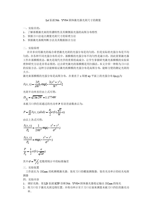
Ld 泵浦Nd :YV04固体激光器光斑尺寸的测量一,实验目的:1, 了解基模激光束的传播特性及其横侧面光强的高斯分布特性2, 掌握刀口法逐点测量光斑尺寸的原理方法3, 掌握激光基模判断方法及其数据拟合方法二.实验原理在许多应用激光的场合希望激光光斑的光强分布是均匀的,但是实际的光强分布是不均匀的,在各种不同光强分布形式中,基横模的光强分布不均匀性是最小的,因此需要激光器工作在基横模状态,激光是现代光学的重要组成成分,让学生掌握研究激光基横模的实验原理和研究方法是非常必要的,过去研究激光的基横模是用扫描法,本文介绍一种称为刀口法的实验方法,这种方法能够验证激光机横模的光强分布是高斯分布,能够方便的测定光斑的大小。
激光束基横模的光强分布是高斯分布,在垂直于z 周德xy 平面上的光强分布I(x,y)为2202222()(,)exp[]P x y I x y W W π+=- 光斑半功率直径由上式可得:121.1774D W ==未被刀口挡住而通过的光功率P 有误差函数表示为:0(,))2P P I x y dxdy erfc ==⎰⎰ 由以上各式可得: 22220(,)1exp()2I x y x y P πσσ+=- 2220(,)exp()I x y x y P σ+=-012P erfc P = 其中2W σ=是数理统计中的标准偏差三.实验装置工作波长为532nm 的机横模激光器,装有刀口的螺旋测微器,装有光功率计的硅光电探测器四,实验内容1, 调好光路,使LD 泵浦KTP 倍频Nd :YVO4固体激光器稳定输出532nm 的绿光2, 将刀口位于激光光斑边缘位置,并将功率计至于刀口后面来测量未被刀口挡住的激光功率。
3,测量此时的激光的输出功率P04,缓慢旋转螺旋测微仪,推进刀口,每0.04mm测一对应的激光功率P,记录下来5,重复4,直到光斑全部被刀口挡住,即功率计显示为0,由此建立P-x曲线6,数据拟合及处理得出光斑尺寸及机横模的判断结果实验数据:第二组:(注:想尽大量办法都没办法找到或编辑erfc()函数,所以没有拟合数据,望谅解)测量两组数据是为了使得结果更精确实验感想:这次实验最大的特点是数据很多,一共测两次,每次的数据有250组数据以上,而且所拟合的函数erfc()很难找,拟合时的难度也比较大,而其他的如实验步骤倒是很清晰简单,不过在实验时也遇到了一些小问题,如在光功率读数比较大时读数很不稳定,所以此时所读的数基本上都是估读的,不过当光功率比较小时,读数就稳定多了。
激光光斑尺寸测量方法我折腾了好久激光光斑尺寸测量方法,总算找到点门道。
一开始我真的是瞎摸索。
我最先想到的方法呢,就是拿尺子去量。
你能想象多傻吧,激光打在墙上形成的光斑,模模糊糊的,尺子根本就不精确啊。
这个办法肯定是不行的,这算是我第一个失败的尝试。
然后呢,我就想是不是可以用相机拍照,然后在电脑上根据照片的比例来计算光斑尺寸。
我拿我的普通数码相机就咔咔拍了不少照片。
但是这里就有个大问题,普通相机镜头会有畸变,你根本没法保证拍出来的光斑形状是准的,这就导致计算出来的尺寸误差超级大。
我那时候就意识到,没专业摄影设备这种方法不靠谱。
我后来还试过用一种特制的透明薄膜,想把光斑投射到薄膜上,用标记笔围着光斑边缘画一圈,然后再精确测量这个圈。
结果发现这个薄膜还是会对激光产生折射之类的,搞得光斑边缘乱糟糟的,也不准确。
再后来我就学聪明了点。
我弄来了一个光学传感器,这个就比较高级了。
就像是给光斑找了一个特别细心的小管家,能精确感应到光斑的边界。
但是这里面也有不少要注意的地方呢。
这个传感器要精心调校,就好像你给小管家安排工作,得跟他说清楚规则一样,要精确调整传感器的灵敏度还有扫描范围之类的。
要是没调好,还是会出错。
比如说灵敏度太高,可能就把周围的杂光也当成光斑一部分了;要是太低,又可能测不全光斑边缘。
还有就是如果测量的环境光线有干扰的话,数据可能也不准。
就像你在一个大吵大闹的市场里面听别人说话,容易听错是一个道理。
所以要是能控制环境光就尽量控制,暗一点的环境测量结果会更好。
目前我觉得用光学传感器这个方法还是不错的,但是我知道肯定还有其他更好的办法,我还在继续探索,要是哪天我有了新的发现,肯定第一时间再跟你说说。
氦氖激光束光斑大小和发散角的测量实验目的1、 掌握测量激光束光斑大小和发散角的方法。
2、 深入理解基模激光束横向光场高斯分布的特性及激光束发散角的意义。
实验仪器氦氖激光器、光功率指示仪、硅光电池接收器、狭缝、微动位移台等。
实验原理1、激光原理概述普通光源的发光是由于物质在受到外界能量作用,物质的原子吸收能量跃迁到某高能级(2E ),原子处于此高能级的寿命约为891010s -- ,即处于高能级的原子很快自发地向低能级(1E )跃迁,产生光电磁辐射,辐射光子能量为21h E E ν=-这种辐射为自发辐射,此辐射过程是随机的,即各发光原子的发光过程各自独立,互不关联。
各原子发出的光子位相、偏振态和传播方向也各不相同。
另一方面由于原子能级有一定宽度,所发出的光的频率也不是单一的。
根据波耳兹曼分布规律,在通常热平衡条件下,处于高能级的原子数密度远低于处于低能级的原子数密度。
因此普通光源所辐射出的光的能量是不强的。
由量子理论可知,物质原子的一个能级对应其电子的一个能量状态。
描写原子中电子运动状态,除能量外,还有轨道角动量L 和自旋角动量s ,它们都是量子化的。
电子从高能级态向低能级态跃迁只能发生在1L =±的两个状态之间,这是选择原则。
若选择原则不满足,则跃迁的几率很小,甚至接近零。
在原子中可能存在这样一些能级,一旦电子被激发到这一能级上,由于不满足跃迁的选择规则,可使它在这种能级上的寿命很长,不易发生自发跃迁,这种能级称为亚稳态能级。
但在外加光的诱发下可以迅速跃迁到低能级,并发出光子。
此过程称为受激辐射,是激光的基础。
受激辐射过程大致如下:原子开始处于高能级(2E ),当一个外来光子所带的能量h ν正好为某一对能级之差(21E E -),则这原子在此外来光子的诱发下由2E 跃迁至1E ,发生受激辐射,并辐射一个光子。
受激辐射的光子有显著的特点,就是受激辐射发出的光子与诱发光子为同态,即两光子的频率(能量)、发射方向、偏振态以及光波的相位都完全一样。
激光光斑尺寸的测量和研究摘要激光光斑尺寸是标志激光器性能的重要参数,也是激光器在应用中的重要参量。
本文主要介绍了两种测量激光光斑尺寸的方法:刀口扫描法,CCD 法。
分析了利用刀口法测量高斯光束腰斑大小的测量实验装置,并阐述了具体的测量过程。
此方法对激光光斑大小测量是可行的。
实验装置简单实用。
CCD法是利用CCD作为探测传感器,可以更精确地测出激光器的光斑尺寸和束腰光斑尺寸,克服了传统测量的繁杂过程,并用计算机控制及数据处理,测量精度得到提高,为激光器性能研究和光信息处理提供了一种新的方法。
本文给出了这两种方法测得的数据及处理结果。
结果表明,刀口扫描法对高能量光束半径的测量特别实用,装置简单,可在普通实验室进行测量。
CCD法检测的直观性好,不需要辅助的逐行扫描机械移动,成像精度和检测精度高。
关键词激光光斑尺寸;Matlab;CCD传感器;刀口法The Measurement and Research of Laser SpotSizeAbstractThe size of Laser spot is not only one important parameter of laser performance, but also in laser application.This paper introduces two methods of measuring laser spot diameter: scanning method, CCD: knife method. We analyze of measurement is cut the size of the gaussian beam waist measurement device spot, and elaborates on process of the measurement. Using this method of laser spot size measurement is feasible. The experiment device is simple and practical. CCD method uses the CCD sensor as a detection can be more accurate to measure the size of the laser spot and waist size spot, overcoming traditional measurement process and using computer control to deal with data processing, and the measurement accuracy is improved, providing a new method for laser performance study and light information processing. At the same time, it gives two methods of measured data and processing results.The results show that the method of blade scanning is practical for high-energy beams radius’s measurement. Simple device can be operated in ordinary laboratory. CCD detection method is visually good, and do not need to manufacture progress ive-scan auxiliary of the machine movement, the imaging accuracy and precision is the higherKeywords Laser spot size; Matlab; CCD sensor; knife-edge method.哈尔滨理工大学学士学位论文目录摘要 (I)Abstract (II)第1章绪论 (4)1.1 课题背景 (4)1.2 国内外研究现状 (5)1.3 论文研究的内容 (7)第2章激光光斑测量方法探究 (8)2.1 刀口扫描法测激光光斑直径研究 (8)2.2 CCD测激光光斑直径方法 (12)2.3 本章小结 (20)第3章激光光斑尺寸的测量与数据分析 (21)3.1 刀口法测光斑直径 (21)3.1.1 90/10刀口法理论及方法 (21)3.1.2 计算理论 (23)3.1.3 实验数据处理 (23)3.1.4 实验分析 (25)3.2 CCD法测激光光斑方法 (25)3.2.1 用CCD拍摄光斑图像 (25)3.2.2 Matlab的图片处理 (26)3.2.3 图像处理结果 (26)3.2.4 实验分析 (29)3.3 本章小结 (30)结论 (31)致谢 (32)参考文献 (33)附录A 英文原文 (34)附录B 中文译文 (38)附录C Matlab程序 (42)第1章绪论1.1课题背景激光技术对国民经济及社会发展有着重要作用,激光技术是二十世纪与原子能、半导体及计算机齐名的四项重大发明之一。
Laser Tissue Welding: Laser Spot Size and Beam Profile Studies Abstract :This paper evaluates the effect of laser spot diameter and beam profile on the shape of the thermal denaturation zone produced during laser tissue welding. 2-cm-long full-thickness incisions were made on the epilated backs of guinea pigs in vivo. India ink was used as an absorber and clamps were used to appose the incision edges. Welding was performed using continuous-wave 1.06-μm , Nd:YAG laser radiation scanned over the incisions to produce 100-ms pulses. Laser spot diameters of 1, 2, 4, and 6 mm were studied, with powers of 1, 4, 16, and 36 W, respectively. The irradiance remained constant at 1272cm W Monte Carlo simulations were also conducted to examine .the effe ct of laser spot size and beam profile on the distribution of photons absorbed in the tissue. The laser spot diameter was varied from 1 to 6 mm. Gaussian, flat-top, dual Gaussian, and dual flat -top beam profiles were studied. The experimental results showed that 1-, 2-, 4-, and 6-mm-diameter spots produced thermal denaturation to an average depth of 570, 970, 1470, and 1900 m, respectively. Monte Carlo simulations demonstrated that the most uniform distribution of photon absorption is achieved using large diame ter dual flat -top beams.Index Terms — Denaturation, laser biomedical applications, laser materials-processing applications, laser welding, Monte Carlo methods, optical propagation.MATERIALS AND METHODSA. ExperimentsIn vivo welding of skin incisions was performed at constant irradiance to investigate the effect of various laser spot sizes (1-, 2-, 4-, and 6-mm-diameter FWHM) on the extent of thermal denaturation at the weld site. Adult female albino guinea pigs (Hartley, age 7–8 weeks, weight 400–500 grams) were shaved then epilated with a chemical depilator (Nair,Carter-Wallace, Inc., New York, NY). Each guinea pig was anesthetized with atropine (0.05 mg/kg), ketamine (30 mg/kg), and xylazine (2 mg/kg) administered by intraperitoneal injection. 1% lidocaine with 1:100000 epinephrine was used as a local anesthetic at each incision site. 2-cm-long, fullthickness incisions were made parallel to the spine with a no.15 scalpel. Four incisions were made on the back of each guinea pig. Approximately 2–5 l of India ink (black India Rapidograph ink, 3080-F, 100-nm particle diameter, Koh-INoor, Bloomsbury, NJ) were applied to the wound edges with a micropipette. The animal was then placed prone on a translation stage, in preparation for surgery. Clamps were used to temporarily appose the incision edges during welding.Welding was performed with a continuous-wave (CW), Nd:YAG laser (Lee Laser, Model 703T) emitting 1.06m μ radiation that was coupled into a 600m μ -core diameter optical fiber (Thor Labs, Newton, NJ). A stepper-motor-driven translation stage (Newport, Irvine, CA) scanned the laser beam along the axis of the weld site at speeds that effectively produced 100-ms-long pulses. Seventy scans were made along each weld; the beam stopped at the end of the weld site for 10 s after each scan. To minimize thermal damage to the skin beyond the weld area, high-reflecting metal plates placed on each end of the incision blocked the beam. Experiments were performed at constant irradiance (1272cm w ) comparing laser spot diameters of 1, 2, 4,and 6 mm [full-width at full-maximum(FWHM)], with laser output powers of 1, 4, 16, and 36 W, respectively. The beam profile, as measured by scanning a 200- m-diameter pin hole across the beam, was approximately Gaussian for all spot diameters. The power delivered to the tissue was measured before each weld with a power meter (Molectron PowerMax 5100, Portland, OR). It shows the experimental configuration used for dye-assisted laser skin welding and summarizes the laser parameters for this study.After welding, the anesthetized guinea pig was euthanized with an intracardiac overdose of sodium pentobarbitol (Nembutal, Abbott Laboratories, North Chicago, IL). The dorsal skin, including epidermis and dermis, was excised with a scalpel and then sectioned. Samples were processed using standard histological techniques, including storage in 10% formalin, processing with graded alcohols and xylenes, parafin embedding, sectioning, and hemotoxylin and eosin staining. A minimum of seven samples was processed for each laser spot diameter and beam profile. The 6-mm-diameter spot study was discontinued after grossly obvious burns developed at the wound site.Thermal denaturation measurements were made using a transmission light microscope (Nikon, Japan) fit with crossed linear polarizers (Prinz, Japan). Thermal denaturation was measured laterally from the center of the weld site at three different depths: the papillary dermis, mid-dermis, and base of the dermis. The depth to which one observed denaturation was recorded and divided by the skin thickness to obtain the fraction of a full-thickness weld that was achieved. Measurements were made consistently to the point at which complete thermal denaturation of the tissue was observed.Statistical analyzes were conducted on the histological data. ANOV A was used to determine statistical significance of thermal denaturation measurements between laser spot size groups.B.Monte Carlo SimulationMonte Carlo simulations were run to investigate the effect of various spot sizes (1–6-mm diameters) and beam profiles (Gaussian versus flat-top and single versus dual beam) on the distribution of absorbed radiation. All simulations were run using code available over the public domain . Several changes were made in the Monte Carlo code to adapt it for use with the geometry of this application. First, because the vertical ink layer in the tissue disrupted the cylindrical symmetry assumed in the Original program, the data were stored in Cartesian rather than cylindrical coordinates and a convolution program was not used to generate the laser beam profile. The beam profile was, instead, created using a random number generator ; a large number of photons was used to create the desired beam profile. Second, the vertical ink layer was modeled as an infinite absorber extending from the skin surface to the base of the dermis with a uniform thickness of 100 m. The experimentally measured absorption coefficient for the ink, was 3500 cm. Even though histologic analysis of the welds showed variable staining of the tissue with a lateral thickness varying from 40 to 100 m, since the ink layer thickness was much greater than the probability that a photon could cross the ink layer was negligible, and the assumption that was infinite is reasonabl e.Third, the skin was modeled as a single dermal tissue layer with the assumption that the epidermis and subcutaneous tissue have optical properties similar to that of the dermis. Finally, even though the optical properties of tissue are known to be temperature-dependent, with the dermal scattering coefficient initially increasing with temperature for temperatures less than 60 C then decreasing sharply at higher temperatures and the dermal absorption coefficient decreasingwith increasing temperature , the optical properties in this model were assumed to be static. This assumption, which avoided a complete optical-thermal model, will result in a slight underestimation of the penetration depth of the photons in the dermis. The optical properties of guinea pig skin at a wavelength of 1.06m μ have not been well characterized. The optical properties for human, pig, and rat dermis were therefore. compiled from several sources. The optical properties used in the Monte Carlo simulations are listed in Table II. Note that in the experimental irradiations, the irradiance was held constant at 127 2cm W . For the simulated irradiations, the mean irradiance over the full-width, halfmaximum of each beam was constant (10 photons per 1-mm-diameter area). The grid element size in the tissue was fixed at 100 m, and the dimensions of the tissue (length width depth) were 1.0 cm 1.0 cm 0.5 cm, respectively. The tissue thickness was, in part, chosen based on the knowledge that human skin may be thicker than guinea pig skin, ranging in thickness from 1 to 4 mm. Simulations were run on a Pentium 133 MHz PC computer (Micron, Nampa, ID)running Microsoft Windows 95 (Microsoft, Redmond, WA) III. RESULTSA. ExperimentsHistologic analysis showed that only shallow welds were achieved using a 1-mm-diameter laser irradiation area. Thermal denaturation was observed only to a depth of 570±100m μ (mean ±S.D.,n=7) or 30% of the average dermal thickness of 1900±200m μ , see Table III. Thermal denaturation lateral to the incision was limited to m μ30100± near the tissue surface. An image of a weld created with a 1-mm-diameter spot is shown in.When the laser spot diameter was increased to 2 mm, thermal denaturation was observed down to the middle layers of the dermis, as show. The thermal denaturation extended to an average depth of m μ210970±(n=7)(p<0.001) or 50% of the dermal thickness. This depth was significantly greater than achieved with a 1-mm-diameter spot Significantly more la teral thermal denaturation was also measured at the surface of the skin, m, than for the 1-mm-diameter spot.Increasing the spot diameter to 4 mm resulted in welds with an average depth of m μ1901470±(n=7) , or 80% of the dermal thickness 。
激光光斑尺寸的测量和研究摘要激光光斑尺寸是标志激光器性能的重要参数,也是激光器在应用中的重要参量。
本文主要介绍了两种测量激光光斑尺寸的方法:刀口扫描法,CCD 法。
分析了利用刀口法测量高斯光束腰斑大小的测量实验装置,并阐述了具体的测量过程。
此方法对激光光斑大小测量是可行的。
实验装置简单实用。
CCD法是利用CCD作为探测传感器,可以更精确地测出激光器的光斑尺寸和束腰光斑尺寸,克服了传统测量的繁杂过程,并用计算机控制及数据处理,测量精度得到提高,为激光器性能研究和光信息处理提供了一种新的方法。
本文给出了这两种方法测得的数据及处理结果。
结果表明,刀口扫描法对高能量光束半径的测量特别实用,装置简单,可在普通实验室进行测量。
CCD法检测的直观性好,不需要辅助的逐行扫描机械移动,成像精度和检测精度高。
关键词激光光斑尺寸;Matlab;CCD 传感器;刀口法The Measurement and Research of LaserSpot SizeAbstractThe size of Laser spot is not only one important parameter of laser performance, but also in laser application.This paper introduces two methods of measuring laser spot diameter: scanning method, CCD: knife method. We analyze of measurement is cut the size of the gaussian beam waist measurement device spot, and elaborates on process of the measurement. Using this method of laser spot size measurement is feasible. The experiment device is simple and practical. CCD method uses the CCD sensor as a detection can be more accurate to measure the size of the laser spot and waist size spot, overcoming traditional measurement process and using computer control to deal with data processing, and the measurement accuracy is improved, providing a new method for laser performance study and light information processing. At the same time, it gives two methods of measured data and processing results.The results show that the method of blade scanning is practical for high-energy beams radius’s measurement. Simple device can be operated in ordinary laboratory. CCD detection method is visually good, and do not need to manufacture progress ive-scanauxiliary of the machine movement, the imaging accuracy and precision is the higherKeywords Laser spot size; Matlab; CCD sensor; knife-edge method.目录摘要 .......................................................................................................... I Abstract .................................................................................................. II 第1章绪论 (1)1.1 课题背景 (1)1.2 国外研究现状 (2)1.3 论文研究的容 (4)第2章激光光斑测量方法探究 (5)2.1 刀口扫描法测激光光斑直径研究 (5)2.2 CCD测激光光斑直径方法 (9)2.3 本章小结 (17)第3章激光光斑尺寸的测量与数据分析 (18)3.1 刀口法测光斑直径 (18)3.1.1 90/10刀口法理论及方法 (18)3.1.2 计算理论 (20)3.1.3 实验数据处理 (20)3.1.4 实验分析 (22)3.2 CCD法测激光光斑方法 (22)3.2.1 用CCD拍摄光斑图像 (22)3.2.2 Matlab的图片处理 (23)3.2.3 图像处理结果 (23)3.2.4 实验分析 (26)3.3 本章小结 (27)结论 (28)致 (29)参考文献 (30)附录A 英文原文 (31)附录B 中文译文 (35)附录C Matlab程序 (39)第1章绪论1.1课题背景激光技术对国民经济及社会发展有着重要作用,激光技术是二十世纪与原子能、半导体及计算机齐名的四项重大发明之一。
三十多年来,以激光器为基础的激光技术在我国得到了迅速的发展,现已广泛用于工业生产、通讯、信息处理、医疗卫生、军事、文化教育以及科学研究等各个领域,取得了很好的经济效益和社会效益,对国民经济及社会发展将发挥愈来愈重要的作用。
由于激光具有很好的单色性、相干性、方向性和高能量密度,它已渗透到各个学科领域,形成了新的学科。
例如:激光信息存储与处理、激光材料加工、激光医学及生物学、激光通讯、激光印刷、激光光谱学、激光化学、激光分离同位素、激光核聚变、激光检测与计量及军用激光技术等,极促进了这些领域的技术进步和前所未有的发展。
在国民经济中形成新的产业部门。
激光产业正在我国逐步形成,其中包括激光音像、激光通讯、激光加工、激光医疗、激光检测、激光印刷设备及激光全息等,这些产业正在作为新的经济增长点而引起高度重视。
对传统工业的改造将发挥愈来愈显著的作用,激光加工作为先进制造技术已广泛应用于汽车、电子、电器、航空、冶金、机械制造等国民经济重要部门,对提高产品质量、劳动生产率、自动化、无污染、减少材料消耗等起到愈来愈重要的作用。
促进医疗技术进步,提高人民健康水平,激光医疗技术目前已在眼科、外科、科、妇科、耳鼻喉科、心血管科、皮肤科等领域得到广泛应用,激光医疗设备已进入县以上的医院,这对医疗技术的进步和提高人民健康水平起着重要作用。
加速我国国防技术的现代化,激光技术在军事上已应用于测距、指向、制导、通讯及战术武器等,为改善武器装备的性能,提高命中率和可靠性,起到重要的作用,并有一定数量的产品出口。
激光光斑尺寸是标志激光器性能的重要参数,也是激光器在应用中的重要参量。
在工业上的金属精加工,在医疗上的激光缝合技术,在军事上的激光定位等等,这些激光的应用都要依靠调节激光光斑尺寸和能量参数。
因此,对激光尺寸的精确测定是有意义的。
1.2国外研究现状激光以全新的姿态问世已二十余年。
然而,发明激光器的历程却鲜为人知,至于发明者如何从事艰难曲折的探索,就更少人问津了。
其实,每一项重大发明,都是科学家们智慧的结晶,里面包涵着他们的汗水和心血。
自然,激光器的发明也不例外。
说得准确些,对激光的研究,只是到了20世纪50年代末才出现一个崭新阶段[1]。
在此之前,人们只对无线电波和微波有较深研究。
科学家们把无线电波波长缩短到十米以,使得世界性的通讯成为可能,那是30年代的事情。
后来,随着速调管和空穴磁控管的发明,科学家便对厘米波的性质进行研究。
二次世界大战中,由于射频和光谱学的发展,辐射波和原子只间的联系又重新被强调。
大战期间,科学家们发明并研制了雷达(战争对雷达的制造起了推动的作用)。
从技术本身来说,雷达是电磁波向超短波、微波发展的产物。
大战以后,科学家又开创了微波波谱学,目的是探索光谱的微波围并把其推广到更短的波长。
当时,哥仑比亚大学有一个由汤斯领导的辐射实验小组,他们一直从事电磁方面以及毫米辐射波的研究。
1951年,汤斯提出了微波激射器的概念。
经过几年的努力,1954年汤斯和他的助手高顿、蔡格发明了氨分子束微波激射器并使其正常运行。
这为以后激光器的诞生奠定了基础。
当时,汤斯希望微波激射器能产生波长为半毫米的微波,遗撼的是,激射器却输出波长为1.25cm的微波。
微波激射器问世以后,科学家就希望能制造输出更短波长的激射器。
汤斯认为可将微波推到红外区附近,甚至到可见光波段。
1958年,肖洛与汤斯合作,率先发表了在可见光频段工作的激射器的设计方案和理论计算。
这又将激光研究推上了一个新阶段。
现在,人们都知道,产生激光要具备两个重要条件:一是粒子数反转;二是谐振腔。
值得注意的是,自1916年爱因斯坦提出受激辐射的概念以后,1940年前后就有人在研究气体放电实验中,观察到粒子反转现象。
按当时的实验技术基础,就具备建立某种类型的激光器的条件。
但为什么没能造出来呢?因为没有人,包括爱因斯坦本人没把受激辐射,粒子数反转,谐振腔联系在一起加以考虑。
因而也把激光器的发明推迟了若干年。
在研究激光器的过程中,应把引进谐振腔的功劳归于肖洛。
肖洛长期从事光谱学研究。
谐振腔的结构,就是从法——珀干涉仪那里得到启示的。
正如肖洛自己所说:“我开始考虑光谐振器时,从两面彼此相向镜面的法——珀干涉仪结构着手研究,是很自然的。
”实际上,干涉仪就是一种谐振器。
肖洛在贝尔实验室的七年中,积累了大量数据,于1958年提出了有关激光的设想。
几乎同时,许多实验室开始研究激光器的可能材料和方法,用固体作为工作物质的激光器的研究工作始于1958年。
如肖洛所述:“我完全彻底地受到灌输,使我相信,可以在气体中做的任何事情,在固体中同样可以做,且在固体中做得更好些。
因此,我开始探索、寻找固体激光器的材料。
”的确,不到一年,在1959年9月召开的第一次国际量子电子会议上,肖洛提出了用红宝石作为激光的工作物质。