上航737AMM手册使用方法介绍
- 格式:ppt
- 大小:4.18 MB
- 文档页数:48

![AMM手册的使用[1]](https://uimg.taocdn.com/35a670c39ec3d5bbfd0a74ac.webp)
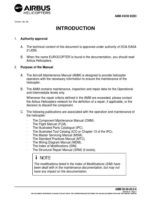
Version: B2, B3INTRODUCTION1.Authority approvalA.The technical content of this document is approved under authority of DOA EASA21J056.B.When the name EUROCOPTER is found in the documentation, you should readAirbus Helicopters.2.Purpose of the ManualA.The Aircraft Maintenance Manual (AMM) is designed to provide helicopteroperators with the necessary information to ensure the maintenance of thehelicopter.B.The AMM contains maintenance, inspection and repair data for the Operationaland Intermediate levels only.Whenever the repair criteria defined in the AMM are exceeded, please contactthe Airbus Helicopters network for the definition of a repair, if applicable, or thedecision to discard the component.C.The following publications are associated with the operation and maintenance ofthe helicopter:-The Component Maintenance Manual (CMM).-The Flight Manual (FLM).-The Illustrated Parts Catalogue (IPC).-The Illustrated Tool Catalog (ICO or Chapter 13 of the IPC).-The Master Servicing Manual (MSM).-The Standard Practices Manual (MTC).-The Wiring Diagram Manual (WDM).-The Index of Modifications (SIM).-The Structural Repair Manual (SRM) (if exists).The modifications listed in the Index of Modifications (SIM) havebeen dealt with in the maintenance documentation, but may nothave any impact on the documentation.In addition to the AMM, the corresponding engine publications (EMM) areprovided with each helicopter delivered.(1)Identification: Information for warehouse staff-Illustrated Parts Catalog (IPC)-Illustrated Tool Catalog (ICO or Chapter 13 of the IPC)(2)Special: Time-sensitive information-Service Bulletin (SB)-Alert Service Bulletin (ASB)3.Definition of required maintenance levels for application of the repairsThe various maintenance tasks are classified in levels so as to take into account the complexity of the tasks, the place of execution of the operations, the equipment and the training of the personnel.For structural repair requirements, these levels are defined by the letters "O", "I", "I+"and "D":-“O” LEVEL (Operation Level): This refers to implementation of simple structural repairs, carried out during line maintenance by the crew and/or line mechanicsusing limited equipment, in order to maintain the operational capability of theaircraft.-“I” LEVEL (Intermediate level): This refers to implementation of small repairs on or out of the aircraft, in a repair workshop using fixed facilities, by skilled,trained and qualified personnel, in order to restore the operational capability ofthe aircraft or equipment.For the "O" and "I" levels, repairs may be carried out in accordancewith the instructions of Airbus Helicopters publications: AMM /SRM / MTC.The rules defined for the "O" level are applicable to the "I" level.-“I+” LEVEL: This refers to implementation of repairs on the primary structure or on stressed composite parts, with the approval of the Airbus HelicoptersTechnical Support Department,. In a Repair Center mandatorily approved by Airbus Helicopters,. Or with mandatory Technical Assistance from Airbus Helicopters if the work iscarried out of an Airbus Helicopters Approved Repair Center,. Or with the assistance of an Airbus Helicopters Approved Repair Center if the work is performed out of an Airbus Helicopters Approved Repair Center.“I+” level repairs require approval from the Airbus HelicoptersTechnical Support Department. The repair work must be approvedby Airbus Helicopters ("I+" specific maintenance documentation, orspecific repair sheet submitted to Airbus Helicopters for approval),or transmitted to Airbus Helicopters if already approved by thesupervisory authorities of the repair workshop. The "I+" level workcards are identified in the work card title.The rules defined for the "I" level are applicable to the "I+" level.-"D" LEVEL: This corresponds to repairs which affect the interchangeability of major structural couplings or the general geometry of the aircraft, using toolingwhich ensures interchangeability, by a maintenance center and specialists dulyqualified by Airbus Helicopters.The supply of documentation (SRMD), tooling and "D" level spareparts is reserved for "D" level Maintenance Centers qualified byAirbus Helicopters.An aircraft cannot be reconstituted using the identification plateof an aircraft which has been declared scrapped by AirbusHelicopters without the prior written approval of Airbus Helicopters.The rules defined for the "I+" level are applicable to the "D" level.Airbus Helicopters reminds you that it is forbidden to reuse structural parts orassemblies which have been involved in an accident without prior approval from the Airbus Helicopters Technical Support Department.The major structural couplings are the following:Landing gear attachment points, MGB bar attachments, attachment points ontransmission deck, engine mount attachment points, fuselage/tail boom junction,horizontal stabilizer-Fenestron junction and TGB attachment points.4.Following up the technical publicationsA.The manuals are valid only if they are regularly kept up to date by the users.The Updating department is governed by the “General Terms and Conditions ofSale” appended to any contract.Documentation may be distributed in three formats: Paper/DVD/PDF (e-techpub).B.Advice to operatorsPaper manuals that have not been kept up to date must not be used forhelicopter maintenance. They must be destroyed on the spot or clearly marked“documentation not up to date”.DVDs must be replaced when each new revision is issued. A DVD that pre-datesthe latest revision must not be used for helicopter maintenance.The e-techpub documentation is updated directly on the Internet.5.Updating the manualA.Normal Revision (NR)Paper issue:-The Maintenance Manuals are updated by a regular updating system. The revision completely or partially updates the manual. The revisions are issuedwith the modification instructions (Highlights).The user or operator is responsible for ensuring that only the correct issueof the manual is used. The effectivity of the manual is indicated on the titlepage.-All the modifications (new, canceled or superseded pages) made to the manuals must be incorporated and recorded in the update list.-Follow the Highlights: these will ensure that the manual is compliant with its new composition, each chapter complying with its own list of effective pages(LOEDU).-The modifications are identified as follows:. All modifications to, additions to or deletions from a text or modifications toa figure are indicated by a black line in the margin.. If part of the text is relocated this may result in changes to the numbering ofthe pages, tables or figures but these changes are not indicated.. All the pages of a modified page block show the modification date.PDF issue:-The Maintenance Manuals are updated by a regular updating system. The revision completely or partially updates the manual. The revisions are issuedwith the modification instructions (Highlights).The user or operator is responsible for ensuring that only the correct issueof the manual is used. The effectivity of the manual is indicated on the titlepage.-The modifications are identified as follows:. All modifications to, additions to or deletions from a text or modifications toa figure are indicated by a black line in the margin.. If part of the text is relocated this may result in changes to the numbering ofthe pages, tables or figures but these changes are not indicated.. All the pages of a modified page block show the modification date.DVD issue:-The Maintenance Manuals are updated by a regular updating system. The revision completely or partially updates the manual. The revisions are issuedwith the modification instructions (Highlights).The user or operator is responsible for ensuring that only the correct issue ofthe manual is used. The effectivity of the manual is given by the "LOIM" (listof manuals included in the DVD-ROM).. If part of the text is relocated this may result in changes to the numbering ofthe pages, tables or figures but these changes are not indicated.. All the pages of a modified page block show the modification date.6.Temporary Revision (TR)A.GeneralBetween two Normal Revisions, Airbus Helicopters may need to makemodifications to points of the manual considered important; this will be donethrough temporary revisions. The Temporary Revision deals with informationwhich requires quick distribution and which cannot wait until the next normalrevision is issued.Several Temporary Revisions may be issued between two Normal Revisions.The new, revised or deleted Documentary Units (DU) are issued on yellow colorpaper. The changes are indicated by a vertical line in the margin.Temporary Revisions are identified by the number of the next Normal Revisionfollowed by a letter (taken in alphabetical order) and a date code.position and updatingThe Temporary Revision is composed of an "Update instructions" section, a Listof Effective Pages of the Temporary Revision, one (or several) List(s) of EffectivePages for the chapter(s) and one (or several) Documentary Unit(s).The "Update instructions" section gives a list of the highlights of the TemporaryRevision. This information is issued with each new Temporary Revision (TR).The List of Effective Pages of the Temporary Revision (LOEDU-TR) identifiesthe chapters modified by all the Temporary Revisions. The date code associatedwith the Documentary Unit corresponds to the date of the Temporary Revision at which it was modified. This list is issued with each new Temporary Revision and supersedes the previous one. It must be inserted at the beginning of the manual in the preliminary Documentary Units and kept until the next Normal Revision (RN).The List of Effective Pages of the chapters "XX-LOEDU-TR" identifies the new, revised or deleted Documentary Units of the chapters affected by the Temporary Revisions. The date code associated with the chapter corresponds to the date of the TR at which it was modified. Only the List of Effective Pages of the modified chapters are issued. These lists must be inserted at the beginning of the chapters concerned and they cancel and supersede the previous ones. They must be retained until the next RN.New, revised or deleted Documentary Units:-For a new Documentary Unit: the new yellow-colored Documentary Unit must be inserted directly in the manual.-For a revised Documentary Unit: all the pages of the yellow-colored revised Documentary Unit cancel and supersede all the pages of the white-colored Documentary Unit concerned. This white-colored Documentary Unit must be removed from the manual.-For a deleted Documentary Unit: only the first page of the Documentary Unit that must be removed is issued on yellow-colored paper through theTemporary Revision. This page bears the word "DELETED". It cancels and supersedes all the pages of the white-colored Documentary Unit concerned.This white-colored Documentary Unit must be removed from the manual.ALL TEMPORARY REVISIONS INCORPORATED INTOTHE MANUAL MUST BE RECORDED IN THE RECORD OFTEMPORARY REVISIONS.PDF issue:The Temporary Revision is composed of "Highlights", a List of Effective Pages of the Temporary Revision, one (or several) List(s) of Effective Pages and one (or several) Documentary Unit(s).The "Highlights" list the major points of the Temporary Revision. This information is issued with each new Temporary Revision.The List of Effective Pages of the Temporary Revision (LOEDU-TR) identifiesthe chapters modified by all the Temporary Revisions. The date code associated with the Documentary Unit corresponds to the date of the Temporary Revision at which it was modified. This list is issued with each new Temporary Revision andsupersedes the previous one. It must be inserted at the beginning of the manualin the preliminary Documentary Units and kept until the next NR.The List of Effective Pages of the chapters "LOEDU-TR" identifies the new,revised or deleted Documentary Units of the chapters affected by the TemporaryRevisions. The date code associated with the chapter corresponds to the date ofthe TR at which it was modified. Only the List of Effective Pages of the modifiedchapters are issued.DVD issue:The Temporary Revision is composed of "Highlights" and one (or several)Documentary Unit(s).The "Highlights" list the major points of the Temporary Revision. This informationis issued with each new Temporary Revision.The "Highlights" of the Temporary Revision identifies the DUs modified by all ofthe Temporary Revisions. The date code associated with the Documentary Unitcorresponds to the date of the Temporary Revision at which it was modified. Thislist is issued with each new Temporary Revision and supersedes the previousone. The manual revision date code is indicated in the "LOIM".ALL TEMPORARY REVISIONS INCORPORATED IN THEMANUAL MUST BE RECORDED IN THE RECORD OFTEMPORARY REVISIONS.7.ErratumThis procedure is used to correct composition errors that do not in any way affect the technical data involving flight safety and the certification of the aircraft. This procedure is used to correct these errors rapidly and is completely separated from the revisions.The date code marked on the replacement page is underlined but it remainsunchanged.Consequently, the page enclosed with the erratum page must replace the pageissued previously.8.PreprintPreprint is a preliminary edition, which is used to transmit an update of the technical documentation in advance of the normal process of management and publication of the information.This procedure is used:-to reply to a customer after he has reported irregularities that require changes to the technical publications,-to introduce new parts and/or systems not included as part of technical publications supplied by Airbus Helicopters.Airbus Helicopters approves the contents of the data transmitted by Preprint.For the approved parts (certification), no page can be sent beforeapproval is granted by the authorities.Rules for the Preprint diffusion process:-The Documentary Units are printed on salmon-colored paper.-The Documentary Units bear the word "PREPRINT" in the diagonal.-The Documentary Units are identified by a new date code.-The Documentary Units must be inserted in place of the modified Documentary Units.Airbus Helicopters preferably transmits the Preprints electronically.In any case no preliminary edition will remain as is. It will always be followed bythe standard procedure of revision (TR and RN). The DUs must be removed by the customer upon receipt of the corresponding DU TR and/or DU RN which take into account the modifications transmitted through Preprint.position of the manualThe Aircraft Maintenance Manual (AMM) is made up of two parts:-Part I of the manual contains all the descriptive type data for all the systems. This Part I is called Systems Description Section (SDS). It is physically separated from Part II and is totally self-contained.-Part II contains the data required for the maintenance and fault isolation operations and procedures.10.Structure of the manualThe AMM is broken down into several levels in accordance with the ATA Specification No.100, Revision 31, with a "Chapter - Section - Subject" numbering system that uses six digits.11.Structure pagesThe AMM contains a series of pages called "Structure pages". They contain general instructions and/or guidelines to find the information.The structure pages contained in the AMM are as follows:-Update instructions.-Title page.-Record of temporary revisions.-List of effective pages of the manual.-Introduction.-List of Service Bulletins.-List of chapters.12.Chapter structure pagesEach chapter starts with a List of Effective Pages of the Documentary Units (LOEDU).This list gives the aircraft version or aircraft serial number effectivity of eachDocumentary Unit.13.Breakdown into chaptersThe manual is broken down into chapters, in accordance with the ATA 100Specification.The chapter below was added:Chapter 01:-List of Materials (in AMM Part II).-List of Critical Parts (depending on aircraft).The numbering principle for the Manual is a breakdown into Chapter - Section -Subject, in a digital form:-the first three digits are given by the ATA 100 SpecificationExample: 62-2x-yz62-2 Main Rotor (system)-the last three digits are left at the manufacturer's disposal:. digit x to complete a sub-system number,. digits yz to complete a sub-sub-system number.Example: 62-2x-yz62-21 Main Rotor Hub (sub-system)62-21-11 Spring vibration damper (sub-sub-system)14.Chapter breakdown into topics (SDS section)Inside the chapters of the manual, the subjects are broken down into topics which gather tasks depending on the maintenance operations.The System Description Section gives explanations on the location, use, description and operation of the complete system and its sub-systems.This section is designed so that it can be used as a training manual.The identification comes in the form of a series of Documentary Units (DU).There are two title levels:-The higher level represents a set of information of the same type (e.g.: General, General Description, Detailed Description, etc.). All the illustrations of a"Documentary Unit" are grouped at the end of this Documentary Unit.Each UD is broken down into subsets.These subsets represent a group of paragraphs.Each subset begins with a title (Introduction, Description, Characteristics,Operation, etc.).15.Chapter breakdown into topics (AMM section)A.Fault IsolationThis section gives the information for the ground maintenance teams to locatefailures and faulty operation and to determine the necessary corrective actions.This topic comes in the form of a table:-The first column "Failure Indication" gives a detailed description of the fault.-The second column "Probable Cause" lists the possible causes of the fault, in the logical fault isolation order.-The third column "Corrective action" indicates the action(s) to be taken to correct each possible cause of the failures listed.B.Maintenance tasksThese topics describe the processes which allow the ground maintenancepersonnel to carry out the maintenance, removal/installation, adjustment, checkoperations, etc.When the task is given for reference, the Chapter - Section - Subject number is followed by the task number:Example: 62-21-00, 4-1 Removal - Main rotor hubIf an instruction requires the execution of a task, its reference number appears between brackets at the end of the instruction.Example: Remove main rotor hub (62-21-00, 4-1).Depending on aircraft configuration, the reference number of the task may be preceded by a configuration number. The selection of this configuration number is the responsibility of the operator.ex: conf 001 62-21-00, 4-1,ex: conf 002 62-21-00, 4-1Further to changes in aircraft configuration, compliance with a Service Bulletin, change of component part number ("Manufacturer Part Number") or a series production modification, the maintenance task can be followed by a configuration letter. The selection of the configuration letter is the responsibility of the operator. Example: 62-21-00, 4-1a Removal - Main rotor hub (PRE MOD 07xxxx) Example: 62-21-00, 4-1b Removal - Main rotor hub (POST MOD 07xxxx)Each task contains the information below:-List of Applicable Documents1. Main informationContains references to other tasks that are essential to carry out theprocedure.2. Conditional informationContains references to other tasks the application of which in the procedure depends on the maintenance environment, the choice or skills of thecustomer.3. General informationContains references to other tasks containing information that is supposedly known by the operator, as well as the code of the manual(s) where suchinformation can be found.-List of special toolsThis is the list of the special tools required to carry out the Task. These "special" tools are those that are not normally available to the maintenance personnel. These tools are identified with their "part numbers" and descriptions.These special tools are listed in the ICO (or in Chapter 13 of the IPC).Certain tools (not listed in the ICO (or in Chapter 13 of the IPC) and not normally available to the maintenance teams) are identified by the term "Commercial" to indicate that they are purchased "off the shelf".-List of MaterialsThis is the list of the consumable materials required to carry out the Task. They are identified with a "CM" code and their description.Details of the products that correspond to these codes are given in W.C.20-01-01-102 of manual MTC.The 20-01-01-102 of MTC describes the "NATO" code, the different references of the French, German and US Specifications and the list of the source products. It also refers to the implementation procedures described in the Standard Practices Manual (MTC) for certain products.Certain materials are identified by the term "Commercial". This means that they can be purchased off the shelf.-List of Routine Replacement PartsThis is the list of the parts discarded and replaced during a Task.This list comes in the form of a table:-the first and second columns give the position of the part (text/figure/set),-the third column gives the name of the part,-the fourth column gives the part number (MP/N).-Job Set-up (optional)This topic specifies how to prepare the helicopter for the work to be done.-ProcedureThe procedure is described in the form of a logical sequence of phases, broken down as follows:(1) phase(a) sub-phase of (1)1 sub-phase of (a)a sub-phase of 1The figures and tables are numbered in chronological order so that they can be used for several phases inside the same Task.All the figures inside a Task are gathered at the end of the Task.The items are identified in a continuous ascending order starting with Item 1 on Set 1 and finishing with Item n on Set m. If a part appears on several figures/sets, it shall always have the same item number.Figure 401 is the first figure in a "Removal / Installation" topic.Table 602 is the second table in an "Inspection / Check" topic.A figure can include several sets. In this case, the figure number remains the same, and only the set number is changed.Furthermore, the items are defined on all the sets of the figure.Figure 401 (Sheet 1)Figure 401 (Sheet 2)If there are no specific indications of the tightening torques onthe figures, then the tightening torque values are the Standardtorque values. To determine this standard value, refer to (MTC20-02-05-404).-Special NotesUSED TO EMPHASIZE A MAINTENANCE OPERATION ORPRACTICE, A CONDITION, A STATEMENT, WICH IF IT IS NOTSTRICTLY RESPECTED MAY CAUSE SERIOUS INJURY ORDEATH.USED TO EMPHASIZE A MAINTENANCE OPERATION ORPRACTICE, A CONDITION, A STATEMENT, WICH IF IT IS NOTSTRICTLY RESPECTED MAY DAMAGE OR DESTROY ANEQUIPMENT ITEM OR PREVENT FULL COMPLETION OF THEMISSION.Used to emphasize an operation or a condition that with help thepersonnel or simplify a maintenance procedure.-Close-up (optional)This topic specifies how to return the helicopter to its initial configuration (asbefore the maintenance operation).16.SymbologyAll the symbols used in the maintenance publications (SDS and AMM Part II) are explained in the following table.17.List of AbbreviationsAFNOR: Association Française de Normalisation (French Industrial Standards Association)ALL P/N: All part numbersAMM: Aircraft Maintenance ManualASU: Ancillary System UnitCBP: Circuit-Breaker PanelCHK: Condition Check - Airworthiness limitationCM: MaterialCMM: Component Maintenance ManualCSS: Chapter - Section - SubjectD: DayDC: Direct CurrentE: Maintenance Due TimeEASA: European Aviation Safety AgencyELT: Emergency Locator TransmitterEMB: Electrical Master BoxEMM: Engine Maintenance ManualESD: Electrostatic Discharge Sensitive DeviceFC: Functional Check (quantitative)FLM: Flight ManualFM: Log cardH: HourHP: High PressureHT: Hard TimeHz: HertzICS: Intercommunication SystemIGE: In Ground EffectIPL: First Limitation IndicationLACU: Lighting and Ancillaries Control Unit LED: Light-Emitting DiodeLH: LeftLP: Low pressureM: MonthMOD 07 xxxx: ModificationMOD AL xxxx: Minor (simplified) modification MOD OP xxxx: Modification of optional equipment MGB: Main GearboxMP/N: Manufacturer's Part NumberMRH: Main Rotor HubND: Not DescribedNF: Free Turbine rpmNR: Rotor rpmOAT: Outside Air TemperatureOC: On Condition (check, maintenance)OGE: Out of Ground EffectOPT: OptionalOTL: Operating Time LimitPCB: Printed Circuit BoardPTT: Push To TalkRH: RightSDS: System Description SectionSLL: Service Life LimitS/N: Serial NumberSP: Static PressureTBD: To Be DefinedTBO: Time Between OverhaulsTGB: Tail GearboxTP: Total PressureTRH: Tail Rotor HubTSI: Time Since InstallationTSM: Time Since ManufactureU: Operating CycleVEMD: Vehicle & Engine Multifunction DisplayW: WeekWDM: Wiring Diagram ManualY: Year18.GlossaryATTACHMENTThe visual check is carried out on the attachment points of a component (condition of the safetying, marks on self-locking nuts). It may be necessary to complete this examination with a tactile check (manual application of a load on the component to detect any fault in the assembly).CHECKA check consists in comparing the measurement of a magnitude (force, time,pressure, temperature, length, etc.) with a theoretical value. The resulting actionconsists in bringing back this magnitude to a value that ranges within its tolerances, through adjustment or a maintenance action (e.g.: check of tightening torques, check of play, etc.).CLEANLINESSThe cleanliness check consists in making sure that there is no foreign matter, no fluid seepage or splashes and no "fouled" areas likely to conceal a fault.CONDITIONThe visual examination concerns the general external condition of a component and the points that could modify its initial condition (deformation, breaks, cracks, scores, corrosion, signs of overheating or wear).。
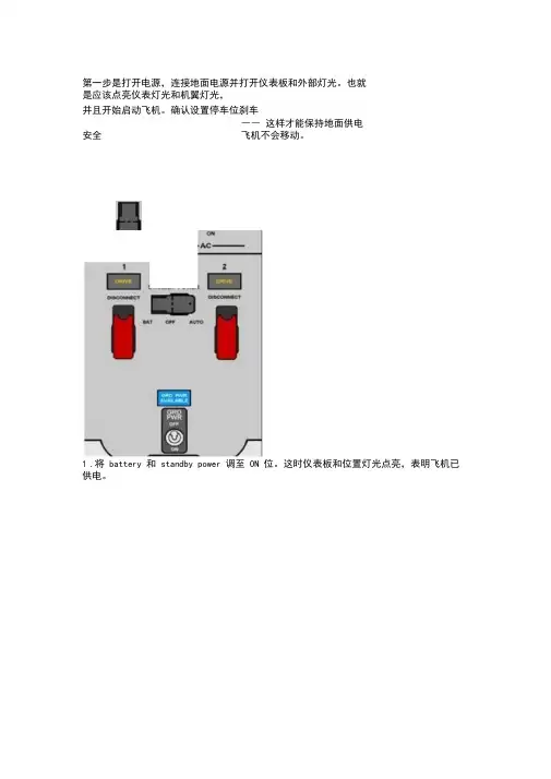
第一步是打开电源,连接地面电源并打开仪表板和外部灯光。
也就是应该点亮仪表灯光和机翼灯光,并且开始启动飞机。
确认设置停车位刹车―― 这样才能保持地面供电安全飞机不会移动。
1.将battery 和standby power 调至ON 位。
这时仪表板和位置灯光点亮,表明飞机已供电。
2. 将GRD PWR switch 调至ON 位。
此时飞机由ground power unit (GPU) 供电。
第二步,现在开启Auxiliary Power Unit (APU)。
APU 可以为飞机供电供气,使我们客舱舒适,同时能启动发动机。
没有bleed air(引气)是不可能打开空调系统和启动发动机的。
1.打开left forward fuel pump ,使其给APU 供油。
如果你使用APU 的时间很长,那还得将left center pump 打开,防止燃油不平衡。
2.将APU switch 调至START 位―― 它会归位到ON 并启动APU。
等排气温度Exaust Gas Temperature (EGT)上升并稳定后,再进行下一步。
3.当APU GEN 灯亮起后,将两个APU GEN都调至ON。
APU GEN OFF灯熄灭后,电力就由APU 供给了。
第三步,下面进行顶板设置,要遵循从上到下,由左及右的设定方法驾驶舱头顶板1. 把 Yaw Damper 调至ON 。
Yaw Damper 灯会亮 它会防止 "Dutch Roll (荷兰滚) ",并可以减少方3. emergency exit 护盖盖好 , "no smoking" 和 "fasten belts" 调至ON/AUTO2. GALLY 电门调至ON4. 因为是今天的首班飞行,将 ignition switch 调至 "IGN R"。
其余飞行就用 "IGN L" ―― 绝不可用OTH"。
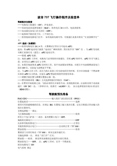
737操作手册波音737飞行操作程序及检查单驾驶舱安全检查──电瓶电门接通位(ON),护盖盖好。
──直流电流表选择电瓶位(BA T),检查电压26±4伏,电流表指零。
──电动液压泵电门在关闭位(OFF)。
──起落架手柄在放下位,三个绿灯亮。
——检查地面电源电门打开。
如有地面电源可用,可接通汇流条并核实“汇流条断开灯”灭。
APU起动(如需要)──检查电瓶电压26±4伏,火警测试正常后方可起动APU。
起动:将APU起动电门扳致“起动位”瞬间保持,然后松开至“ON”位,当APU发电机关断汇流条灯亮(蓝色),APU起动完毕。
──接通APU电源。
注:地面APU工作时,电瓶电门必须保持在接通位,否则APU将停车。
APU作引气源之前,必须先让APU运行1分钟。
注:如果在地面要求APU长时间工作,而中央油箱加有燃油,应把左中央油箱燃油泵电门放在ON位,以防起飞前燃油不平衡。
注:当APU正在工作,而且飞机汇流条上有交流电的任何时候,至少应该接通一个燃油增压泵给APU压力供油,以延长APU燃油控制组件的使用寿命。
──襟翼手柄位置与襟翼位置指示器一致。
──惯导基准系统(IRS)方式选择钮扳至导航位(NA V)。
注:在惯导开始校准之前,飞机必须停住并保持不动,直到校准结束。
注意核实两个直流接通灯(ON DC)亮,三秒钟后灭,校准灯(ALIGN)亮。
显示选择钮放在航向/状态位(HDG/STS)。
驾驶舱预先准备FMC/CDU………………………………输入现在飞机实际位置(PPOS)位置起始页……………………………………………………………选择使用可用的最精确的信息,在调定IRS位置线上输入现在位置,证实方框提示符由输入的现在位置替代。
音频选择板-一调定。
飞行操纵面板…………………………………………………………检查所有5个电门护盖——盖好。
备用襟翼主电门-OFF。
偏航阻尼器电门………………………………………………………OFF仪表和导航转换电门………………………………………………正常位导航转换和显示电门……………………………自动和正常(737-800)燃油系统………………………………………………………………检查翼梁活门关闭灯暗亮(737-800)。
AMM 手册介绍介绍主要以空客手册为主,MD82 和 MD90 飞机的手册与空客手册基本内容一致。
1. 概述飞机维护手册(AMM)是按照 ATA 100 规范编制的。
飞机维护手册含有正常在停机坪或者在维护机库中完成的,对飞机设备和系统的保养,修理,调节,检验和检查所需信息。
飞机以外设备所需的信息包含在厂家或者制造厂的部件维护手册中。
飞机维护手册也含有关于飞机结构的检查和维护的信息。
当然,结构的修理包含在结构修理手册或短舱结构修理手册内。
用于排除故障所必需的信息被包含在排故手册中。
飞机维护手册含有完成维护评审委员会(MRB)文件和相应维护计划资料(MPD)规定的定期维护程序所必要的数据。
手册中使用公制和非-公制测量系统。
在原来的参考文件里使用的度量衡单位数值先列出,然后在括号中换算成另一单位的量值。
客户代码和修订日期出现在每页的底部,修订日期可以是原版日期,修订日期或者最新版日期。
2. 手册划分飞机维护手册分成各章节飞机概述章时限/维护检查...... 5 尺寸和区域...... 6 顶起与支撑...... 7 校水平和称重...... 8 牵引和滑行...... 9 停放和系留 (10)铭牌和标志...... 11 勤务...... 12 飞机机体系统标准实施-机身...... 20 空调 (21)自动飞行...... 22 通讯...... 23 电源...... 24 设备/装饰...... 25 防火...... 26 飞行操纵...... 27 燃油...... 28 液压源...... 29 防冰和防雨...... 30 指示/记录系统...... 31 起落架...... 32 灯...... 33 导航系统...... 34 氧气...... 35 气动系统...... 36 水/废水 (38)机载辅助电源...... 49 结构结构 (51)舱门...... 52 机身...... 53 短舱/吊架...... 54 安定面...... 55 窗...... 56 机翼 (57)动力装置标准实施-发动机…… 70 动力装置…… 71 发动机…… 72 发动机燃油和控制…… 73 点火…… 74 空气…… 75 发动机操纵…… 76 发动机指示………… 77 排气…… 78 滑油…… 79 起动…… 80 2.1 章节划分规则每个章/系统细分成节/子系统(结合功能/自然组)。

AMM 手册的使用说明及注意事项飞机维护手册(AMM )作为机务的工作指南,是航线维护及机库维修中使用最为频繁的一本手册,所以正确的阅读、理解和使用AMM 是一名机务人员的基本要求及必备素质。
但通过对近期接连发生的几起不安全事件的分析表明,部分机务对AMM 的手册的理解和使用还存在一些问题,针对此问题MD-Q 编制此使用说明及注意事项。
一、 使用说明1. AMM 手册的结构按照ATA100号规范,各种民用航空器技术资料都可按其内容根据下列三种情况予以编号: (1) 系统/章号“系统”是由相关机件所组成的,用以完成某种特定的功能的集合每一系统在手册中都称为“章”,每章都指定一个编号作为这一标准编号中的第一组号码。
(2) 子系统/节号“子系统”是“系统”中的某一部分,每一个系统可以由几个子系统共同组成,每一个子系统还可以再划分为几个子系统。
每一子系统拥有各自的编号作为标准编号规范中的第二组号码。
ATA 对章节的规定到子系统一级,也就是说,第二组号码的第一位(3) 组件/目号“组件”是指组成“系统”、“子系统”并完成一定功能的组件及各个单独的线路、管路等。
“组件”所编的“目号”成为标准编号规范中的第三组号码。
这一编号由组件的制造厂家自行编排除此之外维护手册根据自身的性质,按照工作的不同内容,将页码分成不同的区段。
页码的第一位是功能位,代表该页码段的工作内容和性质。
页码的后两位是顺序的页码,表明的是每页的排序,由于AMM 手册的基本单位是页,因此页码对AMM 手册的查询是一个关键点。
5081--系统/章号子系统/节号组件/目号通讯音频综合REU•201-299 维护措施Maintenance Practices“维护施工”是勤务、拆卸/安装、调整/测试、检查/检验、清洁/喷漆、经批准的修理和适当处的特定步骤的组合。
当要求的维护程序不长并相对简单时,以上的组合组成到“维护施工”标题下。
•301-399 勤务Servicing勤务程序包含在其他维护工作通常要求的程序中,勤务程序应该是独立的,并可常规化或可恢复。