锂电池电动车微型无刷电机控制器规格书
- 格式:pdf
- 大小:328.20 KB
- 文档页数:3
小尺寸低功耗电动车无刷电机控制器研究1. 引言1.1 研究背景随着环境保护意识的增强和能源危机的日益加剧,电动车成为了未来交通工具的重要发展方向。
在电动车的发展过程中,无刷电机技术因其高效率、低噪音、寿命长等优点逐渐成为主流。
而在小尺寸低功耗电动车中,无刷电机的控制器更是关键的核心部件之一。
然而目前市场上存在的小尺寸低功耗电动车无刷电机控制器还存在一些问题,比如体积大、功耗高、效率低等。
因此,对小尺寸低功耗电动车无刷电机控制器进行研究和优化具有重要的意义。
通过对控制器的技术介绍、控制原理、设计与研究、仿真与实验结果分析以及优化方向探讨,可以为小尺寸低功耗电动车无刷电机控制器的发展提供新的思路和方法,推动电动车行业的进一步发展。
1.2 研究意义电动车无刷电机控制器是电动车中至关重要的部件,其性能的好坏直接影响到电动车的性能和稳定性。
在小尺寸低功耗电动车无刷电机控制器研究中,探究其研究意义主要有以下几点:1. 提高电动车的驾驶性能:优秀的控制器可以提高电动车的加速性能和响应速度,使得驾驶更加平稳和舒适。
2. 增强节能环保特性:通过研究控制器可以实现电动车的能量回收和节能功能,减少电能损耗,提高能源利用效率。
3. 提升电动车的可靠性和安全性:稳定可靠的控制器可以有效降低电动车的故障率,提高车辆运行的安全性和稳定性。
4. 推动电动车产业发展:研究小尺寸低功耗电动车无刷电机控制器可促进电动车技术的进步和创新,推动电动车产业的发展和壮大,推动清洁能源汽车的普及和推广。
2. 正文2.1 小尺寸低功耗电动车无刷电机技术介绍随着环保意识的增强和电动车市场的快速发展,小尺寸低功耗电动车无刷电机技术成为了研究的热点。
无刷电机相比传统的有刷电机具有更高的效率、更低的噪音和更长的使用寿命,因此在电动车领域得到了广泛应用。
小尺寸低功耗电动车无刷电机通常采用永磁同步电机结构,其转子与定子之间通过永磁体产生磁场,不需要外部励磁,减少了能量损耗和电磁干扰。
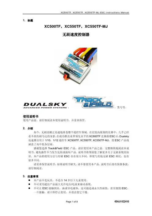
1. 标题XC500TF,XC550TF,XC550TF-MJ无刷速度控制器,,货号等。
使用说明书使用产品前,请仔细阅读本使用说明书,并妥善保管。
2. 介绍如今,无刷浪潮正迅速地席卷整个遥控车领域。
在比较高级别的比赛中,几乎已经看不到有刷马达的身影。
在成功推出业界领先水平的XC800TF竞赛级ESC后,Dualsky 迅速推出用于1/10,1/12遥控车XC500TF, XC550TF, XC550TF-MJ,使ESC产品线涵盖了高中低各层面。
感谢您选择Track&Field ESC产品,请在使用本产品之前,完整细致地阅读本说明书,避免操作不当发生危险或损坏产品。
说明书将帮助您了解更多关于无刷系统的知识。
本产品的使用方法与有刷ESC存在很大不同,即使与其他无刷ESC相比,也有很多不同。
请妥善保管说明书,如果说明书缺失,请不要使用本产品。
说明书后部有保修条款,请仔细阅读。
3. 注意事项z本产品不是玩具,不适合14岁以下儿童使用。
z不可采用超出产品最大允许电压/电流来驱动系统。
z不可让ESC接触到水,油或导电液体,这可能造成永久性损伤,甚至烧毁ESC。
一旦接触,请立即停止使用,并设法使它干燥。
z不可剪断或修改原装导线和插头。
z不可拆开产品,更不要修改焊接PCB上的器件。
z不可使用发生破损的产品,这会导致严重的后果,甚至短路。
z不可用任何材料裹覆产品,散热对工作很关键,也不可用金属材料包裹,容易短路。
z不可反接电池极性,这会导致ESC烧毁。
z不可焊接一处超过5秒,产品部件会因过热导致损坏。
建议采用至少60W以上的烙铁。
z确保接线柱没有与金属零件触碰,这会直接导致短路。
z确保导线固定稳固,剧烈晃动会使插头松动。
并且不会触碰到齿轮等旋转部件。
z本产品和与之连接的马达属于大功率系统,为了安全起见,强烈建议调整系统时卸除马达齿轮,头发,衣服以及零件要与动力系统和车体旋转部件保持距离。
z不要全功率空转动力系统,以免导致轴承一些旋转部件的损坏。

感谢您购买本产品!无刷动力系统功率强大,错误的使用可能造成人身伤害和设备损坏。
我们强烈建议您在使用设备前仔细阅读本说明书,并严格遵守规定的操作程序。
我们不承担因使用本产品而引起的任何责任,包括但不限于对附带损失或间接损失的赔偿责任;同时,我们不承担因擅自对产品进行修改所引起的任何责任。
我们有权在不经通知的情况下变更产品设计、外观、性能及使用要求。
我们的产品提供自出厂之日起240天的保修期,详见产品附带的《WARRANTY CARD 》(质量保证卡) 。
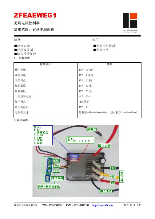
【产品特色】Ì 支持无感(即无霍尔传感器)无刷电机和有感无刷电机。
有感模式兼容NOVAK 、LRP 、FEIGAO 等主流有感无刷电机,无感模式兼容所有无刷电机;Ì 内置开关模式(Switching Mode ) BEC ,具备强大的电流输出能力,无需外挂UBEC ; Ì 主要电子零件被密封,防溅水防尘土。
底面及侧边均有安装孔,方便固定于不同的车架; Ì 全新程序算法,具有优异的启动效果(9种启动加速度)、加速性能及油门线性度; Ì 比例式刹车:4段最大刹车力度调节、8段拖刹力度调节、4段初始刹车力度调节;Ì 多重保护功能:电压过低保护(默认支持锂电池和镍氢电池,设置后可以支持所有类型电池)、过温保护、油门失控保护、堵转保护; Ì 采用软件方式进行进角调整,具有8个进角选项,和传统的进角调整方式(旋转电机后盖以改变传感器的相对位置)具有同等效果; Ì 单键编程设定,且有单键恢复出厂设置的功能;Ì 可选购轻巧便携的车用电调编程设定卡,方便外场使用。
设定卡具有友好的界面,让您轻松设定功能强大的车用电调; Ì 可利用LCD 编程盒(选配件)上的USB 适配器将电调和个人电脑相连,升级电调固件,永久享用最新功能。
Ì 自主知识产权,在必要的情况下,可根据客户要求进行软硬件定制。
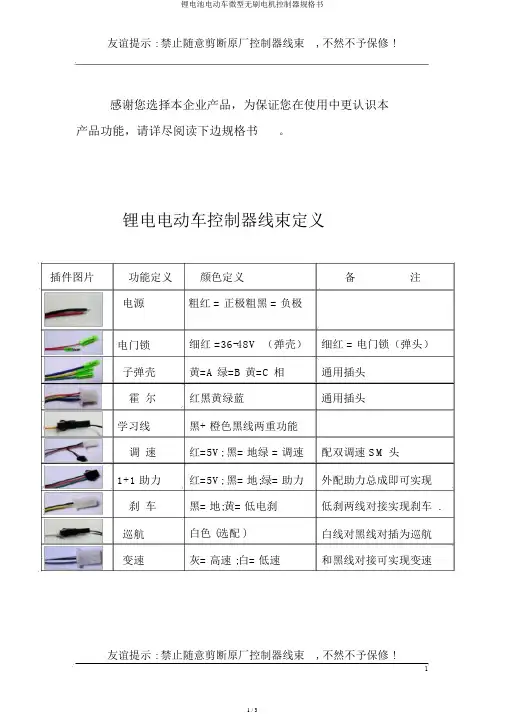
友谊提示 : 禁止随意剪断原厂控制器线束, 不然不予保修 !感谢您选择本企业产品,为保证您在使用中更认识本产品功能,请详尽阅读下边规格书。
锂电电动车控制器线束定义插件图片功能定义颜色定义备注电源粗红 = 正极粗黑 = 负极电门锁细红 =36-48V (弹壳)细红 = 电门锁(弹头)子弹壳黄=A 绿=B 黄=C 相通用插头霍尔红黑黄绿蓝通用插头学习线黑+ 橙色黑线两重功能调速红=5V; 黑= 地绿 = 调速配双调速 SM 头1+1 助力红=5V; 黑= 地;绿= 助力外配助力总成即可实现刹车黑= 地;黄= 低电刹低刹两线对接实现刹车 .巡航白色 (选配 )白线对黑线对插为巡航变速灰= 高速 ;白= 低速和黑线对接可实现变速友谊提示 : 禁止随意剪断原厂控制器线束, 不然不予保修 !1锂电控制器使用方法1.将各功能线正确接入车 ;2.翻开电源 ,电机慢速转 ;3.调整电机方向则拨插学习线;或再拧一次转把(学习线未拔时)4.方向确认后一定拨掉学习线5.拧转加快手把 ,电机正常转动 ,OK!锂电控制器的双门锁线用法说明 :子弹壳长带电 ,实质就是电池的正极电压;子弹头 ,门锁电压输入端,这根线只有接入电池电压控制器才能够工作 .*** 有的车子习惯直接用电池正极粗线接入钥匙开关,这样就友谊提示 : 禁止随意剪断原厂控制器线束, 不然不予保修 !2免却了电门锁线,可是此时一定对插双门锁线.不然控制器不工作 !注:关于不用门锁线的控制器(电池总正极直接接入电锁开关时,原因是当电门长时间封闭后控制器失掉记忆电压后,很少量控制器可能在车电门翻开时反转,此时只要从头学习一下即可。
)使用中控制器常有的问题1.刹车不停电:低电平刹车线接入电池的负极能否可刹车,黄线常态为 4.7-5V 。
2.不可以变速:检查变速线能否接入坚固,电机霍尔破坏也影响变速。
当负载电流超出 8A 时,超速不显然。
查验超速功能能否有效的方法是:将车子架空加快测试。
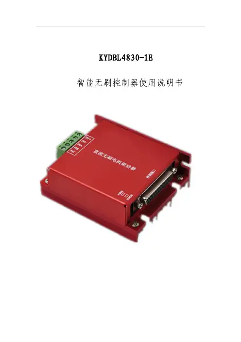
KYDBL4830-1E智能无刷控制器使用说明书PC系列产品选型表在使用本产品前请您详细阅读本使用说明书。
由于不遵守该使用及安装说明书中规定的注意事项,所引起的任何故障和损失均不在厂家的保修范围内,厂家将不承担任何相关责任。
请妥善保管好文件,如有相关疑问,请与厂家联系。
安全注意事项·请专业技术人员进行安装、连接、调试该设备。
·在带电情况下不能安装、移除或更换设备线路。
·请务必在本产品的电源输入端与电源(电瓶)之间加装必要的保护装置,以免造成危险事故或致命伤害;需要加装:过流保护器、保险、紧急开关。
·请做好本产品与大地、设备之间的隔离及绝缘保护。
·如确实需要带电调试本产品,请选用绝缘良好的非金属专用螺丝刀或专用调试工具。
·本产品需要安装在通风条件良好的环境中。
·本产品不能直接应用在高湿、粉尘、腐蚀性气体、强烈震动的非正常环境下。
该标志表示一种重要提示或是警告。
目录一、概述----------------------------------------------5页二、规格及型号----------------------------------------5页三、产品特性------------------------------------------6页四、性能指标------------------------------------------6页五、外形尺寸------------------------------------------7页六、接线要求------------------------------------------9页七、控制器端子接线说明及端子功能示意图----------------10页八、直流无刷电机的连接及说明-------------------------15页九、编码器的连接及说明-------------------------------16页十、保险、电源开关的连接-----------------------------17页十一、数字量输出-------------------------------------18页十二、LED指示灯状态说明------------------------------19页十三、控制器保护功能说明-----------------------------21页十四、马达控制模式说明-------------------------------22页一、概述:KYDBL4830-1E是一款智能型直流无刷单马达控制器。
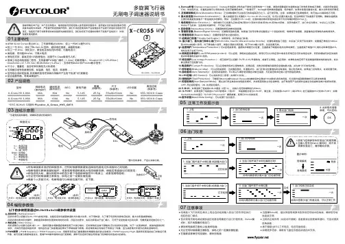
C - C +GNDS TXV-V+多旋翼飞行器● 铝合金散热器,帮助减缓温升。
● 电调接入飞行系统后,每次上电会自动检测输入的油门信号,然后执行 相应的油门模式;● 首次使用无刷电调或更换遥控设备后需要进行油门行程校准;Dshot 模 式时,将不再需要校准油门;● 请勿刷写除其它固件,以免损坏电调;● 无论任何时候都要注意极性,供电之前一定要反复检查;● 在插拔或者做任何连接时,请关闭电源;4. 此时电机准备*图片仅供参考,产品以实物为准。
以下的参数需要通过BLHeliSuite32调参软件设置BEC 瞬间电流(散热良好)尺寸(供参考)重量(供参考)锂电节数典型应用(供参考)持续电流(散热良好)型号L ED 设置650-1200 X -Class100A5-12S25.5gNo55x28x10mmX-Cross HV 3-80A80ANo1. 启动功率(Rampup power ):启动功率可以设置为从3%-150%的相对值。
这是在启动和提高转速时允许最大功率。
对于低转速,为了便于低反电动势电压检测,最大功率是被限制的。
启动功率也影响双向操作,参数是用来限制在更改转向时的功率。
在启动过程中,实际功率取决于油门输入,可低于设定的最大启动功率,但最低是设定的四分之一。
2. 电机进角(Motor timing ):电机进角可以设置为1°-31°,通常设置中等数值进角即适用于大部分电机,但如果电机运转不顺畅时,可以尝试改变进角。
对于一些高感电机,其换向退磁时间自动 或 较长,尤其在低速运转的时候,电机会在油门快速增加的情况下停转或者不顺畅。
将进角改高会有有助于改善这个现象,因为高进角允许更长的换向退磁时间。
3.PWM 频率 (PWM frequency ): PWM Frequency Low - 低频率在低油门最需要的时候提供良好的主动制动;PWM Frequency High -高频率在更高的油门时使运行更 平稳,或可设置为根据转速变化。

修订记录版本 V1.2 日期 2008/03/05 作者 修订内容 应用于电动自行车控制板(通用版)规格说明 V1.21.1 控制器电气规格型 式 额定功率 额定电压 欠压保护 限流电流 :直流无刷电机 (120度/60度) :800W~1000W :48V :42V(可调) ±0.5V :32A~45A(可调) ±1A1.2 功能特点描述该控制板有以下功能: 1. 堵转保护 2. 电机相线短路保护 3. EBS 电子刹车功能 4. 自动和手动巡航功能 5. 三档变速功能 6. 倒车功能 7. 防飞车功能 8. 智能限流保护 9. 智能欠压回差保护 10. 智能能量反馈式刹车充电功能 11. 多重限流保护 12. MOS 管自检功能 13. 同步整流技术 14. 1:1 助力功能 15. 防盗报警锁死电机功能 16. 超静音 17. 120 度/60 度电机选择功能 详细说明如下: z 堵转保护 堵转保护,是指电动自行车超载时,或是在爬坡时电流过大或 者是阻力过大时,,导致电机停止转动,系统能检测到这种现象,并 堵转1.5秒以上控制器自动保护, 自动停止电机输出, 防止烧毁电机, 起到保护作用。
另外,刹车、转把复位等操作可以解除堵转保护, 起到保护作用。
z 电机相线短路保护 在控制器工作时会对电机相线进行检测, 如发现电机相线短路, 控制器会立刻关闭输出,从而及时保护控制器不被损坏。
z EBS电子刹车功能 开机检测到断电刹车方式选择接口为低电平则为EBS电子刹车 功能,否则为普通断电刹车方式。
柔性 EBS 再生制动, 解决了普通刹车断电带来的噪音和对电机 冲击损伤,并且制动迅速,实现了和汽车 ABS 刹车一样的舒适性。
再生制动能将整车的动能衰减部分通过电机发电转换为电能储存 到电池中以供再利用,并能去电池硫化。
z 自动和手动巡航功能 开机检测到手动/自动巡航接口为低电平则为自动巡航方式, 否则为手动巡航方式。
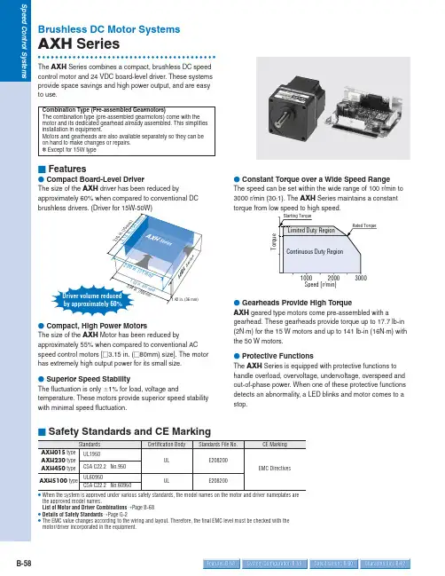
B-58Features B-58Specifications B-60Characteristics B-62System Configuration B-59Brushless DC Motor SystemsAXH SeriesThe AXH Series combines a compact, brushless DC speed control motor and 24 VDC board-level driver. These systems provide space savings and high power output, and are easy to use.ⅥFeaturesⅷCompact Board-Level DriverThe size of the AXH driver has been reduced byapproximately 60% when compared to conventional DCⅷCompact, High Power MotorsThe size of the AXH Motor has been reduced byapproximately 55% when compared to conventional AC speed control motors [Ⅺ3.15 in. (Ⅺ80mm) size]. The motor has extremely high output power for its small size.ⅷSuperior Speed StabilityThe fluctuation is only Ϯ1% for load, voltage andtemperature. These motors provide superior speed stability with minimal speed fluctuation.ⅷConstant Torque over a Wide Speed RangeThe speed can be set within the wide range of 100 r/min to 3000 r/min (30:1). The AXH Series maintains a constant torque from low speed to high speed.ⅷGearheads Provide High TorqueAXH geared type motors come pre-assembled with agearhead. These gearheads provide torque up to 17.7 lb-in (2N ·m) for the 15 W motors and up to 141 lb-in (16N ·m) with the 50 W motors.ⅷProtective FunctionsThe AXH Series is equipped with protective functions to handle overload, overvoltage, undervoltage, overspeed and out-of-phase power. When one of these protective functions detects an abnormality, a LED blinks and motor comes to a stop.Speed [r/min]●When the system is approved under various safety standards, the model names on the motor and driver nameplates are the approved model names.List of Motor and Driver Combinations ➝Page B-68●Details of Safety Standards ➝Page G-2●The EMC value changes according to the wiring and layout. Therefore, the final EMC level must be checked with the motor/driver incorporated in the equipment.Combination Type (Pre-assembled Gearmotors)The combination type (pre-assembled gearmotors) come with the motor and its dedicated gearhead already assembled. This simplifies installation in equipment.Motors and gearheads are also available separately so they can be on hand to make changes or repairs.✽Except for 15W typeⅪ-C K 504AXH B-59Dimensions B-62Connection and Operation B-66Motor and Driver Combinations B-65The system configuration shown is an example. Other configurations are available.Mounting Brackets Flexible Couplings DriverPower Supply Cable (Included)ⅥProduct Number CodeGear Ratio or Shaft Type Number : Gear Ratio A : Round Shaft TypePower Supply Voltage K : 24 VDCOutput Power15: 15W (1/50 HP)30: 30W (1/25 HP)50: 50W (1/15 HP)100: 100W (1/8 HP)Motor Frame Size0: 1.65 in. sq (42 mm sq.)2: 2.36 in. sq (60 mm sq.)4: 3.15 in. sq (80 mm sq.)5: 3.54 in. sq (90 mm sq.)SeriesAXH : AXH SeriesⅥProduct LineAXH015K-Ⅺare Geared Type and the others are combination type.●Enter the gear ratio in the box (Ⅺ) within the model name.C : Cable TypeNone : Lead Wire Type✽The permissible load inertia specified above is only applicable for round shaft type. Permissible Load Inertia for Geared Type and Combination Type ➝Page B-61●Enter the gear ratio in the box (Ⅺ) with the model name.●The values for each item is for the motor only.Also, the motor will stop naturally if the load exceeds the permissible load inertia or the overvoltage protection function is activated during load lowering operations.✽2Motor insulation is recognized as class A [221°F(105˚C)] by UL and CSA standards.✽Size of heat radiation plate (Material: Aluminum)AXH230KC-A: 4.53 in. ϫ4.53 in. (115 mm ϫ115 mm), 0.20 in. (5 mm) thickAXH450KC-A: 5.31 in. ϫ5.31 in. (135 mm ϫ135 mm), 0.20 in. (5 mm) thickAXH5100KC-A: 7.87 in. ϫ7.87 in.(200 mm ϫ200 mm), 0.20 in. (5 mm) thickB-60Features B-58Specifications B-60Characteristics B-62System Configuration B-59B-61Dimensions B-62Connection and Operation B-66Motor and Driver Combinations B-65ⅥPermissible Overhung Load and Permissible Thrust LoadⅷGeared Type/Combination TypeⅥPermissible Load Inertia J for Geared Type/Combination TypePermissible Thrust Load: Avoid thrust loads as much as possible. If thrust load is unavoidable, keep it to no more than half the motor weight.●Enter the gear ratio in the box (Ⅺ) within the model name.2 -42●Enter the gear ratio in the box (Ⅺ) within the model name.●A colored background indicates gear shaft rotation in the same direction as the motor shaft; a white background indicates rotation in the opposite direction.✽Values inside parentheses ( ) are for the AXH015K-Ⅺmodel.Unit ϭ Upper values: lb-in/Lower values: N .mB-62Features B-58Specifications B-60Characteristics B-62System Configuration B-59ⅥDimensions Scale 1/4, Unit = inch (mm)Mounting screws are included with the combination type. Dimensions for screws ➝Page B-133Enter the gear ratio in the box (Ⅺ) within the model name.ⅷMotor/GearheadAXH015K-Ⅺ(Geared Type)Geared motor: AXHM015K-ⅪWeight: 1.1 lb. (0.5 kg)ⅷRound Shaft TypeAXH015K-AMotor: AXHM015K-A Weight: 0.55 lb. (0.25 kg)d A389ⅥSpeed — Torque Characteristics[o z -i n ]0.10.2Speed [r/min][N •m ]T o r q u eSpeed [r /min]00.1T o r q u e[o z -i n ][N •m ]AXH230KC-Ⅺ/AXH230KC-AAXH015K-Ⅺ/AXH015K-A●For the geared type and combination type, the values are for the motor alone.●Enter the gear ratio in the box (Ⅺ) within the model name.Speed [r /min][N ⅐m ][o z -i n ]T o r q u eSpeed [r /min]0.10.20.3z -i n ]0[N •m ]T o r q u eAXH5100KC-Ⅺ/AXH5100KC-AAXH450KC-Ⅺ/AXH450KC-A✽Values for 24 VDC with no extension cable✽Values for 24 VDC with no extension cable ✽Values for 24 VDC with no extension cableB-63Connection and Operation B-66Motor and Driver Combinations B-65B-64Features B-58Specifications B-60Characteristics B-62System Configuration B-59ⅷMotor/GearheadAXH5100KC-Ⅺ(Combination Type)Motor: AXHM5100KC-GFH Gearhead: GFH5G ⅪWeight (including gearhead): 6.4 lb. (2.9 kg)d A401AU (GFH5G5ϳ20)A401BU (GFH5G30ϳ100)ⅷRound Shaft TypeAXH5100KC-AMotor: AXHM5100KC-A Weight: 3.1 lb. (1.4 kg)d A402UB-65Dimensions B-62Connection and Operation B-66Motor and Driver Combinations B-65ⅷDriverAXHD15K, AXHD30K, AXHD50K Weight: 0.22 lb. (0.1 kg)d A298ⅷDriver Input Signal Cable (Included)v For 15 W, 30 W, 50 WⅷDriver Power Supply Cable (Included)v For 15 W, 30 W, 50 WAXHD100KWeight: 0.66 lb. (0.3 kg)d A403v For 100 Wv For 100 WⅥList of Motor and Driver CombinationsⅷGeared Type/Combination TypeⅷRound Shaft Type●Enter the gear ratio in the box (Ⅺ) with in the model name.✽Geared Motor ModelB-66Features B-58Specifications B-60Characteristics B-62System Configuration B-59ⅥConnection and OperationⅷConnection Diagrams v 15 W, 30 W, 50 WDriverv 100 WDriver●When the motor cable needs to be extended, use an optional extension cable [sold separately, 4.9 ft. (1.5 m)].Extension Cable ➝Page B-69ⅷTiming Chart●Run/stop, instantaneous stopping and rotation direction switching operations can all be controlled with the ST ART/STOP , RUN/BRAKE and CW/CCW signals.●If both the ST ART/STOP signal and the RUN/BRAKE signal are set to ON (L level), the motor rotates. At this time, if the CW/CCW signal is set to ON (L level), then the motor rotates clockwise as seen from the motor shaft side; if the CW/CCW signal is set to OFF (H level), the motor rotates in the counterclockwise direction.●If the RUN/BRAKE signal is set to OFF (H level) while the ST ART/STOP signal is ON (L level), the motor stops instantaneously. If the ST ART/STOP signal is set toOFF (H level) while the RUN/BRAKE signal is set to ON (L level), the motor stops naturally.●Wait for 10 ms before switching the other input signals.●Do not switch different input signals simultaneously.Wait for 10 ms before switching the other input signals.CW CCW START/STOP InputCW/CCW InputRUN/BRAKE InputINT.VR./EXT.Input Motor operation patternSPEED Output✽ Max. 10 msB-67Dimensions B-62Connection and Operation B-66Motor and Driver Combinations B-65ⅷInput Signal Circuit v Input Circuitv Example of Input Circuit Connection⅐Control by Small Capacity Relay, Switch, or Similar Device⅐Control by ControllerⅥ C-MOS typeⅥ Transistor output type)Switch capacity: 24 VDC 10 mADriver internal circuitⅷOutput Signal Circuitv Example of Output Circuit Connection ⅐Output Signal Connections⅐SPEED OutputThe system outputs pulse signals (with a width of 0.3 ms) at a rate of 30 pulses per rotation of the motor output shaft,synchronized with the motor drive. Y ou can measure the SPEED output frequency and calculate the motor speed.⅐ALARM OutputThe ALARM output is normally at the ON (L level) and switches to the OFF (H level) when there is an alarm.⅐ALARM-RESETWhen the motor is stopped, setting this signal to the ON (L level), then returning it to the OFF (H level) resets the alarm.Please return either the ST ART/STOP input or theRUN/BRAKE input to the OFF (H level) before inputting the ALARM-RESET . The ALARM-RESET is not accepted if both these signals are at the ON (L level).Notes:●Output signal is open collector output, so an external power supply (Vcc) is required.●Use a power supply of no more than 26.4 VDC and connect a limit resistance (R) so that the output current does not exceed 10 mA. When using neither the speed output function nor the alarm output function, this connection is not required.T0.3 msMotor speed (r/min)ϭSpeed output frequency [Hz]30ϫ60[r/min ]SPEED output frequency (Hz)ϭ1TB-68Features B-58Specifications B-60Characteristics B-62System Configuration B-59ⅷSpeed Setting Methodv Speed Control by Internal PotentiometerWhen INT .VR/EXT . input is set to the ON (L level), the speed can be set with the internal speed potentiometer. There is no need for this connection when the internal potentiometer is not used.v Speed Control by External PotentiometerWhen separating the motor speed setting from the driver,connect the optional external potentiometer as follows.External speed potentiometer PAVR-20KZ (Sold separately)20406080100500100015002000250030003500S p e e d [r /mi n ]Dial plate valueExternal Potentiometer Scale ϪSpeed Characteristics(Representative Values)v Speed Control by External DC VoltageWhen setting the motor speed with an external DC voltage,do so in the following manner.External DC power supply12345500100015002000250030003500DC voltage [VDC ]DC Voltage ϪSpeed Characteristics(Representative Values)S p e e d [r /m i n ]ⅥAccessories (Sold Separately)ⅷExtension CableThe maximum extended length is 6.6 ft. (2 m).v For 15 W, 30 W, 50 WT wo types of cables are available. Covered lead wire type and ribbon cable type.●CC02AXH [4.9 ft. (1.5 m)]●FC02HBL [4.9 ft. (1.5 m)]v For 100 W●CC02AXH2[4.9 ft. (1.5 m)]Driver SideMotorSideDriverSideSide。
永磁三相无刷电机控制系统说明书上海康丘乐电子电器科技有限公司SHANGHAI KANGQIULE TECHNOLOGY CO.,LTD二0一0年五月康丘乐CTLW系列电动车直流永磁无刷电机控制器使用手册(中小功率部分)适用的产品型号:CTLW4824CTLW4832CTLW4837 CTLW6024CTLW6028CTLW6030 CTLW7214CTLW7220CTLW72241目录第一章概述..................................................3第二章主要特性和规格........................................32.1基本功能..............................................32.2特性..................................................42.3技术参数..............................................52.4型号..................................................5第三章安装方法..............................................63.1安装控制器............................................63.2连线..................................................73.3关于J2第7脚电机相位检测选择信号使用方法........93.4无刷电机控制器总成典型接线图..........................93.5安装后的检查..........................................9第四章维护及附件...........................................104.1清洗.................................................104.2附件(仅对购置控制器总成)...........................11第五章联系方式.............................................122第一章概述本手册对上海康丘乐电子电器科技有限公司(以下简称康丘乐公司)CTLW系列中小功率直流永磁无刷电机控制器产品的特性、安装、使用方法以及维护等方面的知识进行详细地介绍。
凯利小型串励/永磁电动车控制器用户使用手册适用的产品型号:KDS24050EKDS24100KDS24200KDS24100EKDS24200EKDS36050EKDS36100KDS36200KDS36100EKDS36200EKDS48050EKDS48100KDS48200KDS48100EKDS48200EKDS72050EKDS72100KDS72100EKDS72200KDS2200E版本2.62011年3月目录第一章概述 (2)1.1概述 (2)第二章主要特性和规格 (3)2.1基本功能 (3)2.2特性 (3)2.3规格 (3)2.4型号 (4)第三章安装方法 (5)3.1安装控制器 (5)3.2连线 (6)3.3安装时检查 (11)第四章维护 (12)4.1清洗 (12)4.2配置 (12)表1:错误代码 (13)联系我们: (14)第一章概述1.1概述本手册主要介绍凯利公司KDS系列电动车控制器产品的特性,安装使用方法以及维护等方面的知识。
用户在使用凯利控制器之前,请详细阅读本手册,这会帮助您正确的安装和使用凯利控制器。
如果在使用过程中遇到任何问题,请从本文档最后一页查询联系方式与我们联系。
凯利KDS小型串励/永磁系列电机控制器是凯利公司为中小型电动车辆提供的一种高效、平稳和容易安装的电动车控制器。
主要应用对象为电动三轮车、电动摩托车、水泵电机以及工业调速电机控制。
凯利控制器采用大功率MOSFET高频设计,同步整流,快速的PWM调控可以达到最佳效率。
第二章主要特性和规格2.1基本功能(1)故障检测和保护。
可通过LED闪烁代码来识别故障;(2)电池电压实时监控。
电池电压太高或是太低都将停止工作;(3)内置电流检测和过流保护;(4)控制器带有温度测量和保护功能。
在低温和高温情况下,将进行电流削减以保护控制器和电池。
如果控制器温度高于90℃,电流将会急剧下降,达到100℃时会自动切断输出。
型号:BLC-120规格书品名:直流无刷电机驱动器雨田电机有限公司YU TIAN MOTOR CO.,LTDBLC-120A该规格书适用于5A 的BLC-120A 直流无刷驱动器。
1 应用2 额定参数额定电压额定电流峰值电流额定转速DC12V ~30V5A8A适用电动机的最大转速20000RPM额定参数测量办法1 3362 3RVREF+DC-H A L L S E N S O RHW HV HU REF-M O T O R W V U DC+EN BRK F/R COM SV C O N T R O LRUN/ALMBLDC MOTOR DRIVERVDC: +12V ~ +30VPeak PowerP-sv TuneUnit:W12011010090807060504030BLC_120带动电动机自行运转。
连接或断开EN 端和COM 端的连接线可控制电动机的运行和停止。
当EN 端和COM 端连接时,电动机运行。
反之电动机停止运转。
4-2 方向控制连接或断开F/R 端和COM 端的连接线可实现电动机不同方向的运转。
当断开F/R 端和COM 端的连接线时,电动机顺时针运转。
当连接F/R 端和COM 端的连接线时,电动机逆时针运转。
当驱动器递交给客户的时,BRK 端和COM 端并未连接。
当接通电源时,驱动器BLD-120A 便能带动电动机自行运转。
连接或断开BRK 端和COM 端的连接线可控制电动机的自然运行和快速停止。
当断开BRK 端和COM 端的连接线时,电动机运转。
当连接BRK 端和COM 端的连接线时,电动机快速停止。
1 3362 34-3 快速停止4-4-2 通过外部电位器设定使用外部电位器进行调速时,电位器中间引出端连接SV 端,两侧的引出端分别连接REF+、COM 端。
此时的内置电位器(RV)需逆时针旋转至极限位置。
1 3362 33456789101112131514161712SV COM REF+4-4 调速方法4-4-1 通过内置电位器(RV)设定顺时针转动电位器(RV),电动机速度增大。
持续电流(散热良好)瞬间电流(散热良好)BEC 尺寸(供参考)重量(供参考)20A 30A 40A 50A 30A40A 50A 60A 锂电池型号55g 23g 12g 25g 12g51g 49x25.5x10.5mm 29x15.5x6.5mm65x26x15.5mm2-4S2-4S2-4S 2-4S 航模无刷电子调速器说明书感谢您使用本产品!本产品功率强大,错误的使用可能导致人身伤害和设备损坏,强烈建议您在使用设备前仔细阅读本说明书并保存,严格遵守规定的操作程序。
我们不承担因使用本产品或擅自对产品进行改造所引起的任何责任,包括但不限于对附带损失或间接损失的赔偿责任。
我们有权在不经通知的情况下变更产品的设计、外观、性能及使用要求。
FlyDragon Lite 30A FlyDragon Lite 20A 65x26x15.5mm02 产品规格03 连线示意图*每种规格的产品外观有差异,图片为代表型号仅供参考,以实物为准1. 刹车: [1] 无刹车 [2]软刹车 [3]重刹车 [4]很重刹车 (出厂默认值为无刹车)2.电池类型: [1]LiPo(锂电) [2] NiCb/NiMh(镍氢/镍隔) (默认值为Li Po )3.低压保护阈值:低/中/高 [1] 2.8V [2]3.0V [3]3.2V ;默认值为中(3.0V/65%)对于Ni-xx电池组:低/中/高中止电压是电池组初始电压值的50%/65%/75%对于Li-xx电池组:可自动计算电池数量,除了确定电池 类型外无需用户设置。
电子调速器为低压保护点提供了三个选择档位:低(2.8V)/ 中(3.0V)/ 高(3.2V)。
例如:对于一个14.8V/4节的Li-po电池组来说,低压中止保护电压为11.2V低/12.0V中/12.8V为高。
4.进角:[1]0° [2]3.75° [3]7.5° [4]11.25° [5]15° [6]18.75° [7]22.5°[8]26.25° (默认值为15°)低(0°/ 3.75°/ 11.25°/15°/ 18.75°)--为大多数的內转子马达设置高(22.5°/ 26.25°)--为6极和6极以上的外转子的马达设置大多数情况下,15°进角适用于所有类型的马达,但为了提高效率,我们建议对2极马达使用低进角设置(一般的内转子),6极和6极以上(一般的外转子)马达使用高进角。
.注意事项9.1控制方式,当接通220VAC(50Hz)电源,如果没有H/M/L 档位信号输入,则电机处于待机状态;当H/M/L 任何一档有信号输入时,驱动器根据板子拨码开关状态控制电机按照给定的转速运行。
9.2驱动器具备过热保护功能,当驱动器超温时,首先让电机降频运行,如果降频后仍然超温,则切断电机电流,直到驱动器温度降至安全范围内,电机才能重新启动。
9.3驱动器具有过电流保护和堵转保护功能。
9.4电机轴承为精密部件,请勿在转轴上冲击,以防产生噪声,影响使用寿命。
9.5使用环境应避免腐蚀性和其它有害气体对电机的损害。
9.6电机转动时请勿接触电机转轴或旋转部件,以免发生危险。
电机接线图:HM L ACLACN 电源板温控器VA 注:电机选用1台或2台根据客户需求使用。
L NPE火零接地AC220VVm(P)GND (N)Vcc (15V)Vsp (PWM)FG直流电机DC MOTORVm(P)GND (N)Vcc (15V)Vsp (PWM)FG直流电机DC MOTOR ACL ACNH M L.运转测试高中低速测试如图所示将电源的L与调速的H,M,L中的任何一个端子短接即可按照短接的速度指令运行。
.拨码表:拨码状态表,拨码开关共8位,7、8两位为温控器类型选择(厂家内部设置,00为三档温控),1~6位为状态选择。
温控器类型00 (三档温控)序号拨码状态高速H中速M低速L100000061146130620000106394843223000100667506340400011069452835650010007225513726001010750573388700110077759540580011108036174219010000831639438100100108586614541101010088468247012010110911704487精品文档可修改。
持续电流瞬时电流(10S)BEC尺寸(供参考)重量(供参考)锂电池节数型号FlyDragon SLIM-60A60A80A4-6S56gNo64.6x29.5x11.7mm注意:首次使用无刷电调或更换遥控设备后需要进行油门行程校准。
(声音次数>=5次后用一长鸣音”Beeeep--”表示5)进角参数(注:出厂默认为22.51.正常工作模式● 启动保护:当加大油门时,三秒内未能正常启动马达,电调将会关闭动力输出,油门摇杆需再次置于最低点后才可以重新启动马达(出现这种情况的原因可能有:电调和马 达连线接触不良或有断开、螺旋桨被其他物体阻挡等)。
● 过负荷保护:当负载突然变得极大时,电调会切断动力,须油门归零后才可正常操作。
当马达和电调失步时,电调会自动尝试重新启动。
● 油门信号丢失保护:当电调检测到油门遥控信号丢失0.32 秒以上即立即关闭输出,以免因螺旋桨继续高速转动而造成更大的损失。
信号恢复后,电调也随即恢复相应的功率输出。
电调接上电池,等待2S后,马达发出一长一短的鸣叫声,此时表明电调已经准备就绪。
接通接收机电源,确保遥控器和接收机通讯正常后给电调上电● 合理的使用电调可延长使用寿命,在使用过一定时间后,请清理电调上的水渍,污渍,避免电调短路。
● 首次使用无刷电调或更换遥控设备后需要进行油门行程校准;● 当电机出现异常或者要求达到更高转速时,可尝试更改进角参数;● 关于主动续流功能开启或者关闭,以四轴为例,必须保证4个电调的设置保持一致。
设置完毕后需重新上电才能生效;● 电机转向切换功能,设置完毕后需重新上电才能生效。
● 如需更多信息,请联系飞盈佳乐售后或者技术支持。
3.进角参数设定ASCF开关转向反向正常底部开关支持:电机转向选择 (默认为正常);主动续流开启/关闭(默认开启);www.fl1.Normal start-up● Start-up Protection:ESC will cut off output if it fails to start the motor within 3 seconds by accelerating throttle. you need to move the throttle stickback to the bottom position and restart the motor.( The possible causes : Bad connection or disconnection between ESC & motor , propellers areblocked, etc)● Over-load Protection: ESC will cut off power or output when the load suddenly increases to a very high value, normal operation will resume aftermoving the throttle stick to the bottom position. ESC will automatically try to restart when ESC and motor are out-of-step.●Throttle Signal Loss Protection:When ESC detects the loss of throttle signal for over 0.32 seconds, it will cut off power or output immediately toavoid an even greater loss caused by the continuous high speed rotation of propellers. ESC will resume the corresponding output after the normalsignal is restored.:Connect ESC & battery packs, wait for 2 seconds, motor emitscontinuously 1 long and 1 short tone. It means the ESC is readyfor working.Connect the receiver tothe battery, ensure thecommunication is normalbetween the transmitterand receiver, then poweron the ESC.Attention:Please calibrate throttle range when first time to use ESC or change transmitter.( When motor emits tone times ≥After changing timing, please test on the ground before flying.● Reasonable use of ESC can prolong the service life. please clean up the water and stains on the ESC after a certain period of time , to avoid electricshort circuit.● User need to calibrate the throttle range when starting to use a new ESC or change another transmitter.● When some abnormality occurs in ESC driving the motor or need the motor to reach a higher RPM, user can try to change the timing.● ASCF ON/OFF function, must ensure all ESCs setting consistent, it will take effect after power on again.● Motor rotation function ,it will take effect after power on again.● Please contact Flycolor sales or technical support for more information.251400-1069,V1.0 BECCon. CurrentBurst Current(10S)Size(for reference)Weight(for reference)LiPo cellsModelFlyDragon SLIM-60A60A80A4-6S56gNo64.6x29.5x11.7mmASCFONOFFRotationRev.Nor.Switches Support to:1.Change Motor rotation .(Normal is default)2.ASCF function On/Off .(ON is default)www.fl。
持续电流瞬时电流(10S )BEC 尺寸(供参考)重量锂电池节数型号Raptor 390Tower-20A20A30A2-4S19.5gNo典型应用(供参考)130-330多旋翼Raptor 390Tower-30A 30A 40A 2-4S 19.5g No 170-450多旋翼*Raptor 390Tower 电调使用的BLHeli 固件为Flycolor Raptor390 20A Multi ; 飞控使用的是SPRACINGF3;请联系Flycolor 以获取更多信息。
multishot(5-25us )。
41.5x36x15.1mm41.5x36x15.1mm ● 首次使用无刷电调或更换遥控设备后需要进行油门行程校准; ● 使用BLHeli 开源程序,当电机出现异常或者要求达到更高转速时,可尝试更改进角参数;● 可调参软件()升级最新版本BLHeli 开源程序;通过飞控连接BLHeli BLHelisuite ●无论任何时候都要注意极性,供电之前一定要反复检查。
●在插拔或者做任何连接时,请关闭电源。
● 5V 12V 只能用于低功率设备(5V 最大1A ,12V 最大500mA ,12V 只建议用于摄像头)。
●可以做一些减震措施尽量避免震动,因加速度计/陀螺仪对震动很敏感。
●飞控要远离一切磁性材料。
● 如需更多信息,请联系飞盈佳乐售后或者技术支持。
20A 30A 2-4S No 130-330 Multi 30A40A2-4SNo170-450 Multi*Raptor 390Tower ESC is using the Flycolor Raptor390 20A Multi BLHeli firmware ;F.C is using SPRACINGF3 firmware; Please contact Flycolor for more information.Con . CurrentBurst Current(10S)BEC Size(For reference)Weight LiPo cells Typical Applications (For reference)ModelRaptor 390Tower-20A Raptor 390Tower-30A19.5g 19.5g41.5x36x15.1mm 41.5x36x15.1mm● User need to calibrate the throttle range when starting to use a new ESC or another transmitter.● BLHeli open-source firmware, when some abnormality occurs in ESC driving the motor or need the motor to reach a higher RPM, user can try to change the timing.● User also can connect the flight control to the computer to update the firmware or change the setup via configuration software (BLHeliSuite).● Observe polarity at all times. Check and double check before applying power . ● Power off before unplugging ,plugging in or making any connections .● 5V ,12Vsupply is for low-current use only(5V 1A MAX, 12V 500mA MAX,12V is suggested for camera only). ● Keep magnets away from the Flight Controller .● Do everything you can to prevent vibrations. ● Please contact Flycolor sales or technical support for more information.。
感谢您选择本公司产品,为确保您在使用中更了解本产品功能,请详细阅读下面规格书。
锂电电动车控制器线束定义
锂电控制器使用方法
1.将各功能线正确接入车;
2.打开电源,电机慢速转;
3.调整电机方向则拨插学习线;或再拧一次转把(学习线未拔时)
4.方向确认后必须拨掉学习线
5.拧转加速手把,电机正常转动,OK!
锂电控制器的双门锁线用法
说明:子弹壳长带电,实际就是电池的正极电压;
子弹头,门锁电压输入端,这根线只有接入电池电压控制器才可以工作.
***有的车子习惯直接用电池正极粗线接入钥匙开关,这样就
省掉了电门锁线,但是此时必须对插双门锁线.否则控制器不工作!
注:对于不用门锁线的控制器(电池总正极直接接入电锁开关时,原因是当电门长时间关闭后控制器失去记忆电压后,极少数控制器可能在车电门打开时反转,此时只需重新学习一下即可。
)
使用中控制器常见的问题
1.刹车不断电:低电平刹车线接入电池的负极是否可刹车,黄
线常态为4.7-5V。
2.不能变速:检查变速线是否接入牢固,电机霍尔损坏也影响
变速。
当负载电流超过8A时,超速不明显。
检验超速功能是否有效的办法是:将车子架空加速测试。
3.不能助力:拨掉助力总成霍尔插头.测控制器助力红黑线常态
应为4.7-5V,绿线电压应为5V左右.否则不正常.
4.不能定速:检查控制器白色线是否与地线对接,对接后电压为
0V,定速时为0V.不定速为4.7-5V!。