采矿工程专业文献翻译-长壁采煤法三向巷道交叉点的有限元分析
- 格式:doc
- 大小:1.53 MB
- 文档页数:17
采矿工程巷道掘进和支护应用分析发布时间:2022-09-12T02:10:31.203Z 来源:《科学与技术》2022年5月9期作者:张志鹏[导读] 经济的发展,社会的进步推动了我国采矿行业发展的步伐。
张志鹏国家能源集团宁夏煤业有限责任公司红柳煤矿宁夏银川750408摘要:经济的发展,社会的进步推动了我国采矿行业发展的步伐。
中国煤矿大部分是井下开采,在井下开采时需要掘进大量的巷道。
巷道的掘进破坏了围岩的应力平衡,巷道周围的应力会重新分布。
若不对巷道进行及时的支护,则很可能导致巷道出现大变形甚至垮塌,这对确保巷道的安全十分不利。
因此,需要对掘进工作面进行支护设计。
在设计时,一方面要考虑支护的安全性,即保证巷道能长时间处于稳定状态;另一方面要考虑支护的成本,毕竟煤矿企业还需要盈利。
关键词:采矿工程;巷道掘进;支护应用引言为保证煤炭供应量,地下开采已成为一种常态,这就加大了开采的难度,提高了开采的危险系数。
煤矿企业需要采取巷道的安全、稳固措施,做好煤矿掘进支护的保障工作,选择科学适用的支护技术,提高掘进支护技术水平。
1煤矿掘进支护的重要性分析之所以重视煤矿掘进支护工作,主要是基于以下两点考虑。
a)针对煤炭资源的高需求量,做好掘进支护工作,能够保证开采的有序、有效进行,按时完成开采任务。
b)为加强安全生产,需做好安全防控安排。
煤矿掘进支护技术的应用,可以保证作业人员的生命安全和开采工作的顺利、有效开展。
2采矿工程巷道掘进和支护应用2.1综采掘进支护技术应用的关键掘进支护技术应用包括以下几个关键环节:a)要扩大吊环式前探梁的应用范围。
临时支护工作要采用3组吊环式前探梁,吊环式前探梁长度控制在3m左右。
3组吊环式前探梁布置较为简单,1组位于巷道中间,另外2组位于两边,与中间吊环的距离为1.0~1.2m。
b)采用单体柱配π型钢前探梁,长度规定不得小于3.5m,同时,每根前探梁都要有2个以上的固定点。
前探梁与迎头端面的距离要小于0.3m,超前支护体与两帮的距离最好要超过0.3m。
2013 届毕业文献翻译题目文献翻译专业班级采矿工程学号 09010901xx学生姓名刘xx指导教师张电吉指导教师职称教授学院名称环境与城市建设学院完成日期: 2013 年 6 月日Room and pillar Mining MethodsBullock(1982a),quoting previous data, showed that room and pillar mining together with stope and pillar mining accounted for most of the underground mining in the United States. He estimated that 60% of noncoal minerals (about 80 million tons or 70 Mt) and 90% of coal ( about 290 million tons or 260 Mt) were obtained by room and pillar methods, and it is unlikely that things are radically different today. The method is cheap, highly productive, easily mechanized, and relatively simple to design.The room and pillar mining method (Fig.5. 2) is a type of open stoping used in near horizontal deposits in reasonably competent rock, where the roof is supported primarily by pillars. Ore is extracted from rectangular shaped rooms or entries in the ore body, leaving parts of the ore between the entries as pillars to support the hanging wall or roof. The pillars are arranged in a regular pattern, or grid, to simplify planning and operation. They can be any shape but are usually square or rectangular. The dimensions of the rooms and pillars depend on many design factors. These include the stability of the hanging wall and the strength of the ore in the pillars, the thickness of the deposit, and the depth of mining. The objective of design is to extract the maximum amount of ore that is compatible with safe working conditions. The ore left in the pillars is usually regarded as irrecoverable or recoverable only with backfill in noncoal mines.applications of pillar mining have been discussed by Hamrin ( 1982) and Hittman( Anon. . 1976) among others. Suitable conditions include ore that are horizontal or have a dip of less than 30°. A major requirement is that the hanging wall is relatively competent over a short period of time, or is capable of support by rock bolts that are used extensively in room and pillar mining. The method:! is particularly suited to bedded deposits of moderate thickness (2 to 6 m) such as coal-the main application一salt, potash, and limestone.Figure.5.2Room and pillar mining method.1, Methods of Room and Pillar MiningRoom and pillar mining takes place in sections or panels, which are usually rectangular and regular in plan. In hard rock mining of horizontal ore bodies, the method is very similar to open stoping. In many cases, ore grade control may be the primary requirement in mine design, and ground control and ventilation secondary considerations. This may lead to an ad hoc room and pillar design with irregular- , nonrecoverable pillars of low-grade ore.Hard-rock room and pillar mining is a effectively method of open stoping (stope and pillar mining) at a low angle to the horizontal, excavating rooms and leaving supporting pillars.Where mineral values vary, the method is similar to the old “gophering" method of mining where random excavations followed highly mineralized zones. Where mineral values are consistent, the mine layout can be regular. The method differs from most hard-rock mining methods in that gravity flow is limited, and ore must be loaded in the excavation where it has been blasted and transported from that point. In large operations this involves trucks and loaders or load — haul — dumps ( LHDs).There are various methods of room and pillar stoping. The most common are full-face slicing breast stoping and multiple slicing or bench and breast stoping. In the former, the rooms are opened to their full vertical height with no mineral or economic value left in the roof or the floor. probably the reasonable safe limit for full-face slicing is 8 to 10 m depending on drilling and support equipment, and beyond this, multiple slicing is used.2. Production CycleFor hard-rock ore bodies ,the basic cycle is similar to hard-rock tunneling four main elements, (1)mark out and drill blast holes , usually in a wedge pattern , (2) ,and ventilate to remove blast fumes ,(3) introduce mucker and muck and load,and ④scale the face and walls and bolt the roof where necessary. There is considerable complexity in the interaction among these elements that make up a basic critical path. In order to estimate the cycle time, it is necessary to determine unit loading and drilling rates and task times for these elements and also to estimate how subsidiary elements and tasks such as haulage and ventilation takeup may impinge upon the critical path in a badly organized mine.3.Panel DevelopmentA panel layout for a typical room and pillar mine in a noncoal mine is illustrated as follows :The excavation height is about 4.5m,and the normal sloping practice is to drive a single development drift about 10. 5 m wide a distance of about four or five rooms into the ore body. This will serve as the main haulage drift. Pillars are then marked out on the drift walls and rooms driven between them.To drill and blast the initial drive when the only exposed or free face is the drive face, some form of cut pattern is used. This is known as the “ face round or “ swing and in a 4. 5 by 10.5 m face will comprise 60 to 70 holes of about 8 mm to a depth at 3 to 3. 6 m. If more than one face is exposed,a group of holes may be drilled at a low angle to the free face in what is known as a " slab round or slabbing or “slashing”. This requires less explosive and less drilling than a single face. the most common form of face round is a wedge or V, cut although bum cuts can also beDrilling is carried out with jumbo-mounted hydraulic drills ;loading is usually by gathering arm loader, although in modern mines, trackless LHD vehicles are used to the load to a transfer raise where it is reloaded into trucks or conveyors.房柱法Bullock在1982年提出房柱法,它指在矿房与矿柱里回采矿物,在美国大多数地下开采应用柱式开采。
翻译部分英文原文Finite element analysis of three-way roadway junctions inlongwall miningR.N. Singh, I. Porter, J. HematianFaculty of Engineering, UniÍersity of Wollongong, Northfields Avenue,Wollongong, NSW 2522, AustraliaAbstract:This paper presents a three-dimensional finite element analysis of three-way roadway intersections in longwall mining, and assesses the stable/unstable behaviour of three-way intersections under a range of loading conditions. Loads were applied to the model by means of uniform stresses on the internal free faces. This method of loading the model from the inside helped to reduce its size and to eliminate the boundary effects. Stress concentrations and displacement results on the mid-height of the pillars, roof and floor strata adjacent to the three-way intersections and cut-throughs were calculated.Based on this study, guidelines for designing the support system for three-way intersections are suggested. The results were validated by a case study of a three-way intersection in an underground coal mine in the southern coal fields of the Sydney Basin.Keywords:underground coal mining; gate roadway; intersections; stability; finite element method1. IntroductionA trend exists in Australia for installing high productivity longwall faces producing 3.0~4.0 milliontonne raw coal per annum per face. The mainconcern for the success of the high-production longwallfaces is to achieve high rates of developmentand to maintain stability of access roadways andtheir intersections during the life span of the face.Intersections are formed when the pillars betweenthe two roadways are intersected by driving a crosscut. Roadway intersections in underground mines areparticularly susceptible to ground control problemsdue to inherently wide roof spans used and the difficulty in installing roof supports promptly inhighly mechanised headings. Stresses induced duringintersection formation may result inhigh incidenceof roof and rib failures. Despite many investigationsinto the stability of gate roadways intersectionsadverse conditionssuch as high horizontal stress and unsteady state ofabutment pressure from moving longwall faces maycause instability of gate roadway intersections.For example in 1985; major strata control problems inthe main gate of no. 6 longwall panel at WestcliffColliery resulted in roof fall, which stopped coalproduction for a period of 6 weeks. Similarly, a rooffailure incident at Pacific Colliery caused the longwallequipment to be buried resulting in stoppage ofthe longwall operations for a period of 3 months.Thus, unprecedented stratacontrol problems may have significant effects onoverall production from high-productivity longwallsystems even over a short duration.This paper containsan investigation of the application of a three-dimensionalfinite element method to calculate stressesand displacement around three-way roadway intersections.The effects of individual parameters such as depth of cover, the ratio of horizontal to verticalstress (K) and the width of opening on the stability of the three-way intersections are examined. Theresults are compared with the field observations at anunderground coal mine in the southern coal field ofthe Sydney Basin.2. Stability analysis of three-way intersections using three-dimensional finite element modelsThe procedure used in the stability analysis of thethree-way intersections comprised of defining themechanical properties of the rocks surrounding theintersection, the geometry of the intersection and thevirgin state of stress. The stresses and displacements induced around the intersections were computed usinga three-dimensional finite element method. Ifunstable conditions existed, either the design of supportsystem was changed or the geometry of thestructure was modified.Important input data forthese models were vertical stress and the ratio ofhorizontal to vertical stress K for a given lithologyand dimensions of the roadway intersection .Assuming symmetrical conditions around a threewayintersection, only half of the structure wasmodelled using eight-node solid elements comprisinga total of 7190 elements and the 11 597 grid points.The computer running time was 17 h using around 1Gb of memory. The rock mass properties assigned tothe intersection model are presented in Table 1.The loads were applied to the model by means ofuniform pressures on the internal free faces. Thistechnique of applying load from the inside helped to reduce the size of the model and to eliminate boundaryeffects. For all the loading configurations depictedin Table 2, a linear solution method was used.Preliminary computer analysis was carried out tocompute the induced vertical stress distributionthroughout the three-dimensional model for a litho-staticcondition. In order to gain better understandingon the behaviour of the structure, the vertical stressconcentration on various horizontal and verticalplanes was shown for different loading conditions byplotting stress concentration contour lines for variousratios of induced virgin stresses. These results are discussed in the subsequent sections.3. Pillar behaviour at three-way intersectionFig. 2 indicates vertical stress concentration at themid-height of the pillar for various loading configurations.For the litho-static stress condition at K=K x=K y=1, the stress concentration at the midheight of the pillar has a symmetrical pattern (see Fig. 2a). The stress concentration zone on the ribside of the intersection has a width of 2.5 m, equal tohalf the roadway span. The maximum stress concentrationis about 1.4 times the virgin stress for theloading configuration K y>1 for a limited zone at the corner of the pillar.When K y >1, the vertical stress pattern at the mid-height of the pillar is no longer symmetrical;thestress is more pronounced along the roadway perpendicularto the direction of maximum horizontal stress(see Fig. 2b).No tensile zone along the rib side wasdetected. The maximum stress concentration zone islocated close to the edge of the pillar and extends along the roadway perpendicular to the major horizontal stress.4. Roof behaviour at three-way intersectionThe vertical stress distribution on a plane 1.5-mabove the roof line is shown inFig. 3, which indicatesthat the stress is 0.8z σ over the edge of pillar increasing to 1.0z σ at a distance of 6 m within the edge of the pillar. The stress distribution lines abovethe individual roadways show the contour lines atintervals of 0.2z σ.This stress distribution pattern indicates a semi-dome shaped destressed zone overthe three-way intersection. When the ratio of horizontalto vertical stress, K x or K y increases, the stress contour line 0.2 z σ moves towards the centre of the roadway while 1.0z σ line moves further into the pillar indicating that the height of the semi-domeshaped destressed zone becomes shallower in thefield of high horizontal stress.When K x ≠K y , as shown in Fig. 3b, the stresspattern varies over the individualroadways and 0.2z σpartly disappears in the roadway perpendicular to themajor horizontal stress. In this case, the boundary ofthe roof fall in this roadway will be controlled by thestress contour lines of 0.4z σ .However, the rate of changes in stress distribution across the roof line ofthe roadway parallel to high horizontal stress is moresignificant. The height of the roof fall in the roadwayintersection might be evaluated by using appropriatedestressed contour lines on the vertical plane at themid-span of the main roadways and the cut-throughs,respectively, as presented in Figs. 4 and 5. Thejustification of using 0.4z σ contour line to delineate the boundary of roof fall is presented in a subsequentsection.Fig. 5 Vertical stress concentration on the vertical plane at the mid-span of thecut-through.Fig. 5 also indicates that the radius of influence ofthe intersection over theindividual roadways with respect to the stress distribution in the roof is estimatedto be one span from the centre of the intersection.Fig. 6 shows the vertical displacement on the roofline under various loadingconfigurations at the roadwayintersection. The maximum sag occurs at the centre of the intersection and its maximum value is12 mm. It can also be seen that the roadway parallelto the major horizontal stress will show more roofsag than the roadwayperpendicular to the horizontalstress.Behaviour of the floor at the T-junction of athree-way intersection is given in Fig.7 on the floorline for loading configuration K x=1 and K y=2. The floor lift patterns are similar to that of the roofsag except that the amount of the maximum floorheave is much less than the corresponding value forsag.5. Case history of three-way intersectionsAn investigation into the mechanism of instabilityat roadway intersections was carried out at tail gatesof a longwall panel in an underground coal mine inthe southern coal fields of the Sydney Basin. Thefield measurements included roof sag, floor heaveand rib deformation monitoring ahead and behind thelongwall face. The overall objective of this studywas to validate the results of three-dimensional finiteelement modelling of the three-way junction by comparingthe results with the field measurements.5.1. Site location and the description of the site-specific ModelFig. 8 presents the details of the longwall panel, gate roadways and intersections at the site beinginvestigated. The panels were 200-m wide and 2000-m long with a double entry gate roadway system.Each roadway was 5 m wide, 3 m high, with 55×40 m pillars centre-to-centre. The height of extractionvaried between 2.4 and 2.6 m.The actual sites ofmonitoring were 35, 36 and 9 intersections of 24longwall’s tail gate and 35 and 36 cut-throughs. Thevertical stress at the site was 10 MPa at the depth of420 m, the major horizontal stress 25 MPa orientedparallel to the gate roadways andthe minor horizontalstressThe mechanicalproperties of the strata units are shown in Table3. Based on the above information, a number ofthree-dimensional finite element models were constructedand analysed to simulate the existing conditionsaround the sites of investigation. Both inducedstresses and displacements around the roadways andintersections were computed for each site of investigation. The results of the finite element analyses arepresented together with the values obtained from thefield displacement measurements.A series of roof, rib and floor extensometers were installed at and in between 35,36 and 9 cut-throughsahead of 23 longwall panel. The objective of thisstudy was to determine the pattern of deformationaround the area of investigation and provide a measureof ground control. The extensometers site andlocation for principle modes of failure are also presentedin Fig. 8.The roof sag measurements have been carried outat different locations and compared with values predicted by the finite element model.In all cases,Table 3 Mechanical properties of rock at the site of investigationThe differences between the measured and predicted values are very small. Fig.10 indicates typical results of roof sag measurements, together with the predictedvalues of displacements at 9 cut-through, before andafter the longwall face has passed through the monitoringsite.Monitoring continued when the longwallface approached and passed 9 cut-through andreached the end of the panel. Readings were regularlytaken over a period of 45 days, but for the sakeof simplicity, only the initial and final readings areshown.It can be noted that the difference betweenthe initial and final readings was very little. Therefore, it can be concluded that the time dependentdeformation of the roof was very little. In addition,visual examinations indicated that good roof conditionsprevailed throughout the investigation without displaying any strata softening and roof paring the results of deformation at 9cut-through before and after longwall no. 23 passedthe site, it can be seen that tailgate behaviour issignificantly affected by the retreat of the adjacent face.5.2. Rib behaviourThe results of rib extensometers and those predicted by the finite element analysis are presented in Fig. 11. The results indicate a timedependent deformation of 0.4 mm dayy1. As thetime dependent behaviour of the coal seam could notbe modelled in the finite element analysis of thestructure, the predicted values are only the totaldeformation after complete relaxation and thereforeless than the measured values.The important aspect of the chain pillar between35 and 36 cut-throughs is the nature of the ribmovement. The extensometer readings indicate thatthe softening has occurred to a depth of 5 m. This isin contrast to rib behaviour observed at 9 cut-throughwhere the deformation into the pillar rapidly abatesfrom the rib line.5.3. Floor behaviourThe floor extensometers results and the displacementvalues predicted by the finite element method at 35 cut-through are presented in Fig. 12. The plotindicates that although the deformation initiated 5 mbelow the floor surface, the majority of deformationtook place between 1.0 and 1.5 m into the floor.Thus, floor heave takesplace in the broken shale andthe laminated shale units as referred to in the lithologyprofile presented in Fig. 9. Although the shaleunit is surrounded by the laminated sandstone/shale,it can generate an uplift stress in the immediate floorwhen failure occurs within it. The significant floorheave at 9 cut-through is mainly attributed to thehigh horizontal stress and the side abutment stress ofthe longwall face.It has been previously demonstrated in an earlierpublication by the present authors that roadways parallel to the major horizontalstress, where K (K x or K y ) > 1, will have greaterfloor heave and roof sag when compared to road-ways parallel to minor horizontal stress.6. Guidelines for designing the support system at three-way intersectionsThe results of investigation of three-way intersectionsshowed that the maximum vertical stress at themid-height of the coal seam occurs at the corner ofthe pillar and increases with the roadway width andthe depth below surface. The destressed zone overthe pillar extends along the roadway perpendicular to the major horizontal stress.A uniform pattern ofhorizontal dowels in conjunction with wire meshwould be necessary to ensure the integrity of thepillars. A minimum dowel length equal to 50% ofthe entry width at 1.0-m spacing is suggested. Thispattern should be implemented on the edge of thepillar extending along the roadways for a distanceequal to one roadway span. The rest of the pillars inthe individual roadways should be reinforced if necessaryaccording to single roadway conditions.The four potential modes of failure should betaken into account when designing the optimum roofbolt pattern at three-way intersections.The first zoneof instability may manifest itself as a semi-domeshaped failure over the T-intersection. One side ofthe zone is parallel to the left of the main roadwaywith the base being a semi-circle. When K x ≠K y the base of the zone will have a different length ineach roadway, with the longer length perpendicularto the major principle horizontal stress. Although theproperties of the roof strata have significant effect onthe stability of the roof, the stress contour lines 0.1z σand 0.3z σ have been used to define the boundary of the roof failure zone above the three-way intersectionfor K x or K y <2 and K x or K y > 2, respectively However, observations at two field sites in theSouthern Coalfield and Hunter Valley have indicatedthat the height of roof falls is generally governed bythe regional stresses, in particular, the ratio of horizontalto vertical stress, the width of the openingsand mechanical properties of the overlying strata.Previous observations at site 2 in Hunter ValleyCoalfield by one of the authors have indicated thatthe height of roof falls matched very well with thearea under stress contours of 0.3z σ. Therefore, in order to be on a conservative side, a stress contour of 0.4z σwas adopted as a criterion for roof fall height in the present study.The second mode of failure is due to shearingalong the bedding planes, which occurs when theshear stress exceeds the frictional strength of thebedding planes.The most probable location for slidingof bedding planes occurs closer to the rib sidethan to the roadway centre. The required length ofthe fully grouted bolts depends upon the cohesion, the coefficient of internal friction and the location ofthe bedding planes. Thus, a general roof bolt pattern cannot be devised for all conditions and an accurateanalysis of site-specific models based on the accuratefield data is necessary.The third potential mode of failure is gutteringalong and over the rib sides and corners of theintersection. This is more likely to happen when thehorizontal stress is greater than the vertical stress.Inclined roof bolts passing through this zone andanchored over the pillars are a possible solution.The fourth mode of failure is controlled by thepresence of a geological feature in the intersection.When a major geologically weak zone is present inthe area of the intersection, the roof instability ishighly influenced by the structural feature. In thatcase, the prediction of the roof fall would be governedby the orientation and inclination of the geologicalfeature, internal angle of friction and dimensionsof the intersection. In that case, a specialsupport measure will be required to ensure stability.The three-way intersections cause specific stratadisturbances in the vicinity and can be convenientlydivided into two zones as indicated in Fig. 13. Inregion I, which is outside the zone of intersection, the roof condition is the same as in main roadways.Therefore, roof support is carried out based on theprocedure for individual roadways. Region II, whichis within the roadway intersection, experiences increasedstrata loading and therefore special adjustmentto roof bolt length and location must be considered.The roof bolt length must be increased by 50%and the spacing reduced by 25% in comparison tothe bolts in region I. The load carrying capacity ofthe bolt must be calculated according to height of thedestressed zone. It is suggested that in high horizontal stress fields, the roadways running parallel to thehigh horizontal stress must be driven first and thesupport for the completed intersection must be installedbefore the other roadway is inter-connected.Itis also suggested that the installation of inclined roofbolts near the rib and use of w-straps parallel to thepillar edge would help in maintaining structural stabilityof the three-way intersection.7. General discussion and conclusionsDrivage conditions can be significantly influencedby the orientation of roadways with respect to themajor horizontal stress, the effect of side abutmentpressure due to longwall extraction and the presenceof soft strata in the floor. Field investigation indicatedthat the drivage conditions parallel to the majorhorizontal stress were goodwith minimum roof shearfailure.In contrast, the drivage perpendicular to themajor horizontal stress displayed considerable shearzones particularly at locations close to the intersections.An increase in the stress magnitude due to thepresence of geological structures accentuated theshear failure.These situations were well illustratedand predicted during the finite element analysis ofroadways and intersections undervarious configurations and stress regimes.Due to a number of reasons, there are still somedifference between the field measurements and thefinite element model results.Uncertainty regardingthe in situ properties of the strata units, stress regime, the presence of geological discontinues and geologicalstructures may be some of the reasons for thisdiscrepancy. Moreover, lack of consideration to thetime dependent properties of the rock mass anddynamic loading resulting from an approaching longwallface may further contribute to the lack ofaccuracy.This paper contains a successful demonstration ofthe application of the finite element method to thestability analysis of three-way intersections.In general,the significant agreement achieved between thefield measurements and the FE results have provedthat the FEM can be successfully used for the stabilityanalysis of underground structures.Results of investigations on the stability of threewayintersections showed that the general stress and displacement patterns around the three-way intersectionsare the same as in four-way intersections butpresenting less severe instability problems 。
采矿工程巷道掘进和支护要点分析发布时间:2022-05-04T13:41:20.260Z 来源:《中国科技信息》2022年1月2期作者:平万森[导读] 众所周知,在采矿过程中最为重要的环节和输出通道就是巷道。
平万森铁法煤业(集团)有限责任公司小青煤矿辽宁铁岭 112700摘要:众所周知,在采矿过程中最为重要的环节和输出通道就是巷道。
因此,如果在采矿过程中,巷道出现了任何安全隐患,都有可能导致整个采矿工程置于危险的环境之下,影响到开采工作的顺利进行,同时也有可能会威胁到工作人员的生命财产安全。
我们有必要对影响巷道掘进速度的相关要素进行分析和研究,找出最为安全稳妥的巷道掘进方式,促进采矿工程领域获得更加长远的发展。
本文对采矿工程巷道掘进和支护要点进行分析。
关键词:采矿工程;巷道掘进;支护要点一、巷道掘进和支护技术在采矿工程中的应用和价值采矿工作在开展之前,工作人员必须要重视巷道掘进工作的开展,维护巷道掘进工作的安全性,保证在开工的过程中工作人员的人身安全不受到威胁。
如果能使用较为先进的支护技术,就能保证巷道掘进工作能够在相对的稳定的环境中运行。
因此,在进行巷道掘进施工过程中,必须要保持采矿巷道的环境安全,推动后续采矿工作有序进行,在这里我们必须意识到一个现实的问题,在进行巷道掘进作业过程中往往要面临较为复杂的地下环境,如果地下存在较多的软岩土,那么在巷道掘进施工的过程中就容易出现塌方事故,威胁到生命安全。
施工人员要强化支护技术的具体运用,重视决定工作的安全保障,优化工作方式,丰富支护技术的实际使用范围,这样才能为整个采矿工作提供较为安全的施工环境。
二、影响巷道掘进的因素分析1.围岩的强度在采矿工程中,围岩的坚硬与否决定了巷道能否提供支撑保护。
在这个过程中,工作人员如果想要加大围岩的硬度,可以使用锚杆支撑技术,在一定程度上可以提高围岩的支撑强度。
对于采矿中的围岩来说,它可以通过巷道的负载能力来判断地应力,相应地,如果围岩的承载能力比较强,地应压力也会更大,这个时候就需要减小顶板的位移,起到保护和支撑的功效。
外文原文:Adopt the crest of the coal work noodles plank managementproblem studyCrest the plank management is the point that adopts a safe management of the coal work noodles.Statistics according to the data, crest the plank trouble has 60% of the coal mine trouble about, adopting the trouble of the coal work noodles and having a crest 70% of the plank trouble above.Therefore, we have to strengthen a plank management, reducing to adopt the coal work noodles crest the occurrence of the plank trouble.1,the definition of the crest,scaleboard and it categorizeEndow with the existence coal seam on of the close by rock strata be called a plank, endow with the existence coal seam under of the close by rock strata be called scaleboard.Crest the rock,strength of the scaleboard and absorb water sex and digging to work the management of the noodles contain direct relation, they is certain crest the plank protect a way and choose to adopt the empty area processing method of main basis.1.1 planks categorizeAccording to rock,thickness and return to adopt process to fall in the 垮of difficult easy degree, crest the plank is divided into the false crest,direct crest and old crest.According to direct crest sport to adopt a field to the influence for press, the direct crest is divided into broken up,unsteady,medium etc. stability,stability,strong and tough crest plank etc. is five.According to old crest the sport Be work mineral inside the noodles press to present degree and to work safe threat of noodles of size, the old crest is is divided in to press very and severely, press mightiness, press to compare obviously, don't obviously press etc. is four.1.2 scaleboards categorizeAccording to the opposite position relation of the rock strata and the coal seam, the scaleboard is divided into direct bottom with the old bottom.Locate coal seam directly under of the rock strata be called direct bottom;locate the direct bottom or coal seam under of the rock strata be called old bottom.The coal seam crest the scaleboard type expects the influence of the geology structure sport after be subjected to the deposition environment and, its growth in different region degree dissimilarity, the coal seam possibility for have isn't whole.2,crest that need to be control plank classification and adopt the processing way of the empty areaAccording to different crest the plank type and property, choose to pay to protect a way and adopt the empty area processing method differently, is a plank management of basic principle.2.1 crest needed to pull to make plank classificationPress a knothole rock strata strength, the crest plank that needs to be control can is divided into: general crest the plank,slowness descend to sink a plank and is whole fall the crest of the cave in the danger plank etc..2.2 work noodles adopt the processing method of the empty areaThe processing method that adopts empty area mainly has: all 垮s fall a method,partial full to fill a method,the coal pillar to prop up a method to alleviate to descend to sink a method slowly etc..3,crest the plank pressure present a characteristic3.1 top the cover rock strata of the sport regulation and the work in front pay to accept pressure to distribute behindDuring the period of mine, adopt empty area above of the rock strata will take place ambulation, according to crest the plank change mind condition, taking the cranny rock strata in up the cover rock strata follow the work noodles to push forward the direction demarcation as three areas: the coal wall prop up the influence area,leave layer area and re- press solid area.The noodles opens to slice an eye to go to push forward forward in the process from the work, break original should the equilibrium of the dint field, cause should the dint re- distribute.Be adopting the coal work noodles to become to pay to accept pressure in front and back, it concretely distributes shape to have something to do with adopting the empty area processing method.3.2 first times to press to press a main manifestation with the periodFirst time to press a main manifestation:BE a plank"by oneself the vield song" range enlargement;the coal wall transform and fall to fall(the slice help);pay to protect to drill bottom etc..First time to press to want to keep on more and suddenly and generally for 2-3 days.Period to press a main manifestation:Main manifestation BE:crest the plank descend to sink nasty play increment of speed, crest the plank descend to sink quantity to become big;pay what pillar be subjected to load widespread increment;adopt empty area to hang a crest;pay pillar to make a noise;cause the coal wall slice to help,pay pillar to damage,crest plank occurrence the step descend to sink etc..If pay the pillar parameter choice to be unsuited to a proper or single body to pay the pillar stability worse, may cause the partial crest or crest plank follow the work noodles to slice to fall etc..4,crest the plank choice for protectThe work noodles the function for protect decelerate a plank to descend to sink, supporting to control a crest to be apart from the knothole integrity inside the crest, assurance work space safety.4.1 choices that protect material and formPay to protect material to mainly there are the metals support and the wood support.Pay to protect a form to mainly have a little the pillar to protect,the cote type protect to press a support with liquid.4.2s protect a specification choiceWhile choosing to pay to protect specification, mainly control the following 2:00:1.Control the work noodles adopt high and its variety.Generally can according to drill a holethe pillar form or have already dug the tunnel data of to make sure to adopt high.From last the movable regulation of the cover rock strata, can the initial assurance crest plank at biggest control a crest to be apart from place of average biggest descend to sink quantity, select to pay a pillar model number suitablely2 control the crest plank of the normal appearance to descend to sink the quantity and support can the draw back pute the biggest and high Hmax and minimum and high Hmin that pays pillar, select specification of pay the prehensive the pillar model number and specification, check related anticipate, assurance the model number of the pillar.5,the work noodles manages everyday of pointEveryday crest the point of plank management is the with accuracy certain protects density and control a method, right arrangement and organize to adopt coal and control a crest to relate to in fixed time, strengthen to pay to protect the quality management before press, the assistance that chooses to use a good necessity protect etc., attain to expel to emit a trouble, assurance the purpose of[with] efficiency.1 choice that protects density and controls a methodAccording to the work noodles crest plank rock,adopt a periodic to press obvious degree, press strength and to press in front and back a crest knothole variety a circumstance etc., the certain protect density and control a method.It adopt coal in 2 production lines with control of the crest to relate to in fixed timePeriod to don't obviously press to adopt a field, emphasize to pay to protect,adopt coal, control a parallel homework, possibly contract to adopt coal,return to pillar to put distance between an operations with speed the work noodles propulsion degree;period to press more and obviously adopt a field, at to press in front and back adopt different of,control the relation organization project, before press should not adopt coal,put a crest in the meantime homework, press after should adopt to adopt coal,put a crest to keep minimum wrong be apart from parallel homework.Field to strengthen to pay to protect the quality management assurance to pay pillar to have to prop up dint,prevent°from paying pillar to drill bottom enough before press,right adoption the assistance protect.Adopt the coal work noodles crest, the plank manages everyday of the key lie in raising the spot management,the operation level, paying to protect and adapt to adopt a field to press and crest the scaleboard variety circumstance, adopt right of the assistance protect measure, well exertivecontrol a result.译文:采煤工作面的顶板管理问题探讨顶板管理是采煤工作面安全管理的重点。
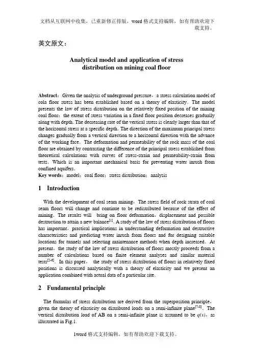
英文原文:Analytical model and application of stressdistribution on mining coal floorAbstract:Given the analysis of underground pressure,a stress calculation model of cola floor stress has been established based on a theory of elasticity.The model presents the law of stress distribution on the relatively fixed position of the mining coal floor:the extent of stress variation in a fixed floor position decreases gradually along with depth.The decreasing rate of the vertical stress is clearly larger than that of the horizontal stress at a specific depth.The direction of the maximum principal stress changes gradually from a vertical direction to a horizontal direction with the advance of the working face.The deformation and permeability of the rock mass of the coal floor are obtained by contrasting the difference of the principal stress established from theoretical calculations with curves of stress-strain and permeability-strain from tests.Which is an important mechanical basis for preventing water inrush from confined aquifers.Key words:model;coal floor;stress distribution;analysis1 IntroductionWith the development of coal seam mining,The stress field of rock strata of coal seam floors will change and continue to be redistributed because of the effect of mining.The results will bring on floor deformation,displacement and possible destruction to attain a new balance[1].A study of the law of stress distribution of floors has important,practical implications in understanding deformation and destructive characteristics and predicting water inrush from floors and for designing suitable locations for tunnels and selecting maintenance methods when depth increased.At present,the study of the law of stress distribution of floors mostly proceeds from a number of calculations based on finite element analyses and similar material tests[2-6].In this paper,the study of stress distribution of floors in relatively fixed positions is discussed analytically with a theory of elasticity and we present an application combined with actual data of a particular site.2 Fundamental principleThe formulas of stress distribution are derived from the superposition principle,given the theory of elasticity on distributed loads on a semi-infinite plane[7-8].The vertical distribution load of AB on a semi-infinite plane is assumed to be q(x),as illustrated in Fig.1.We want to solve the state of stress at a specific point inside a semi-infinite plane,such as point M .Supposing the coordinate of point is (x,z),the micro-1ength dζfrom the origin of coordinate is ζon the AB segment,the micro-concentration force d p=q dζis regarded as its force and the state of stress of the micro-concentration force at point is defined as follows.In order to calculate the stress at point M from all distributed loads,the stress which is caused by every micro-concentration force is superposed.We need to integrate Eq.(1) from ζ= -a to ζ= b and Eq.(1) then becomes:3 Stress calculation of coal seam floor3.1Foundation of the mechanical modelBased on the theory of underground pressure,the mechanical model of supporting pressure in front of the working face can be simplified,as shown in Fig.2[9-11].Where the OA segment is the plastic area,with a length of x0;the AB segment is the elastic area,with a length of L0x0.In order to calculate easily the supporting pressure of both areas p z(1),p z(2),without losing its rational,we can assume the following two linear functions:Where is the supporting pressure of the plastic area(kPa),the supporting pressure of the elastic area(kPa),the maximum stress concentration coefficient,the width of the plastic area(m),H the buried depth of the coal floor(m),the width of the area affected by the supporting pressure(m) and is the average weight of the volume of the over-lying strata (kN/m3) .3.2Stress calculation processAccording to the theory of elasticity on distributed loads on a semi-infinite plane,we can use Eq.(2) to calculate the vertical stresses σz(1) and σz(2) and the horizontal stresses σx(1)and σx(2)which are affected by the supporting pressures and .The stress equations at point M(x, z) can then be obtained correspondingly by superposition (this calculation neglects the effect of the transferred load from the goaf and the overlying strata movement as well as the effect of the initial ground stress because it does not produce subsidiary stress at point M;largely we considered the action of the supporting pressure in front of the working face). The calculations are as follows:Therefore,σz = σz(1)+σz(2)(4) and σx = σx(1)+σx(2)(5). By coordinate transformation(x = x(n = 0,1,2,…)),x is regarded as x0 in Eqs.(4) and (5) and the stress values of each section can be calculated,where the variable expresses the relative distance from the pushing position of the working face to the origin of the coordinate system. Given the related parameters of supporting pressures,the stress values,located at the relatively fixed floor section,(x =) at different depths,can be calculated by computer when the working faces advance.When x = x,Eqs.(4) and (5) can be represented as follows:3.3Example analysisGiven the actual geological conditions and mining technology at the 2702 working face of the Yangcun Colliery of the Yanzhou Mining Group Limited Company,the following related parameters are determined:=3,=5 m,=50 m,=25 kN/m3 and H=500 ing Eqs.(6) and (7),the stress distribution curves are obtained on the relatively fixed floor section x=at different depths with the working face advancing by calculation. The results are shown means of computer in Figs. 3 and 4.Fig. 3 shows that vertical stress maintains its maximum at the interface between the coal seam and floor on the section x=from the original coordinates and then quickly decreases with the increasing depth and slowly decreases at a specific depth. A similar situation is obtained when the working face advances,i.e.,the range of the vertical stress decreases with an increase in depth. From the results it can be seen that the range of depth, given the variation of vertical stress, is relatively large, i.e., within 40 m. The range of the vertical stress is clearly smaller after the working face advances 30 m.According to the relationship of the variation between vertical and horizontal stress, the multiplication of the variation of vertical stress and its corresponding coefficient of horizontal pressure (λ) is equal to the increment of horizontal stress at the point M[1]. Then the increment of horizontal stress and the horizontal stress at the point M continues to be superposed, which is inversed analysis when the working face advances 30 m. The results of the variation in stress show that the vertical stress is larger than the horizontal stress when the working face is at its original position: the maximum principal stress is the vertical stress; the minimum principal stress is horizontal stress. Because the rate of decrease of the vertical stress is faster than the horizontal stress, the horizontal stress is larger than the vertical stress within 42 m when the working face advances 30 m (for details, see Fig. 4). Considering the effect of the variation in vertical stress, the horizontal stress is much larger than the vertical stress. The maximum principal stress is the horizontal stress and the minimum principal stress is the vertical stress. It agrees with the partial reasons of the mechanical principle of floor heave[12-14].Fig. 3 also shows that the variation is almost steady on the section x=when the working face advances 30 m. Therefore, the relationship of variation in stress with depth is calculated when the working face advances from 0 to 30 m. The details are shown in Table 1.Table 1 Data of rock characteristics and correlative stress of the floor on 2702 working face in Yangcun colliery (MPa)岩层深度(m)ΔλλΔx=0 m x=30 m x=30 m x=30 mλΔ泥岩0 37.50 0.00 0.00 0.00 37.500.4316.13 16.13 5 27.25 0.04 2.12 2.08 27.21 11.70 13.78砂岩10 22.53 0.28 3.83 3.55 22.250.327.12 10.67 15 19.95 0.77 4.91 4.14 19.18 6.14 10.28 21 18.17 1.46 5.40 3.94 16.71 5.35 9.29石灰岩25 16.75 2.21 5.46 3.25 14.540.284.07 7.32 28 15.55 2.94 5.24 2.30 12.61 3.53 5.83From the analysis of the related data, the stresses + λΔin Table 1 can be regarded as the stress values,obtained from mechanical rock tests. So the variations of the principal stress from theoretical calculations and the results from the servo-controlled tests can be contrasted. Given these contrasts it is seen that, the largest stress value of mudstone is 16.13 MPa and the largest stress value of sandstone10.67 MPa. When combining Fig. 5 with Table 1 it is seen that, the largest calculated principal stress is less than the peak value of the principal stress in Fig. 5, and the calculated section is at an elastic deformation section of Fig. 5, where permeability is relatively weak. So there is still a certain ability of water resistance. It can be shown that the obvious destruction is not produced in the mudstone and sandstone when the working face advances 30 m. This is essentially consistent with the conclusions of the survey report.4 Conclusions1) Based on the mechanical model of the floor, the analysis of stress distribution is obtained on the relatively fixed floor position with an advancing of working face. Owing to heterogeneity and discontinuity of the rock mass of the coal floor, there is a certain divergence between the ideal model and actual conditions. But from analyses and calculations, the basic variation law of stress distribution is discovered on the relatively fixed floor position with an advancing of working face when specific parameters are given for the working face.2) The decreasing rate of the vertical stress is faster than that of the horizontal stress up to a certain depth and the direction of the maximum principal stress is changed from vertical at the original position to horizontal with an advancing of the working face. The horizontal stress is larger than vertical stress within 42 m when the working face advances 30 m.3) The difference between the theoretically calculated principal stress and the results of the servo-controlled penetrability test can be contrasted. Deformation and penetrability can be obtained from the floor rock mass. From an example, it is seen that the mudstone and sandstone of coal floor are at an elastic deformation stage. There is no extreme destruction on the relatively fixed floor section with an advancing of working face and there still is a certain ability of water resistanceAcknowledgementsHere we express our sincere appreciation to director for Zhao Zhenzhong, minister Song Shun of Zhengzhou Coal Industry Group for their help during the course of the sampling. Appreciating Dr. Xi Yantao of China University of Mining and Technology for his help for modification.References:[1] Zhang J C, Zhang Y Z, Liu T Q. Rock Mass Permeability and Coal Mine Water Inrush.Beijing:Geological Publishing House, 1997. (In Chinese)[2] Miao X X, Lu A H, Mao X B, et al. Numerical simulation for roadways in swelling rock undercoupling function of water and ground pressure. Journal of China University ofMining and Technology, 2002, 12(2): 120-125.[3] Gong P L, Hu Y Q, Zhao Y S, et al. Three-dimensional simulation study on law of deformationand breakage of coal floor on mining above aquifer. Chinese Journal of Rock Mechanics and Engineering, 2005, 24(23): 4396-4402. (In Chinese)[4] Shi L Q, Han J. Floor Water-Inrush Mechanism and Prediction. Xuzhou: China University ofMining and Technology Press, 2004. (In Chinese)[5] Jing H W, Xu G A, Ma S Z. Numerical analysis on displacement law of discontinuous rockmass in broken rock zone for deep roadway. Journal of China University of Mining and Technology, 2001, 11(2): 132-137.[6] Liu Y D, Zhang D S, Wang Ii S, et al. Simulation analysis of coal mining with top-coal cavingunder hard-and-thick strata. Journal of China University of Mining and Technology,2006, 16(2): 110-114.[7] Dun Z L, Gao J M. Mechanics of Elasticity and Its Application in Geotechnical Engineering.Beijing: China Coal Industry Publishing House, 2003. (In Chinese)[8] Xu Z L. A Concise Course in Elasticity. Beijing: Higher Education Press, 2002. (In Chinese)[9] Liu W Q, Miao X X. Numerical analysis of finite deformation of overbroken rock mass in gobarea based on Euler model of control volume. Journal of China University of Mining and Technology, 2006, 16(3): 245-248.[10] Jiang F X. Rock Pressure and Stress Control. Beijing: China Coal Industry Publishing House,2004. (In Chinese)[11] Qian M G, Shi P W. Rock Pressure and Stress Control. Xuzhou: China University of Miningand Technology Press, 2003. (In Chinese)[12] Xu N Z, Tu M. The mechanism and control of floor heave of road driving along next goaf ofhigh seam. Journal of Anhui University of Science and Technology (Natural Science), 2004, 24(2): 1-4. (In Chinese)[I3] Wang W J, Hou C J. Study of mechanical principle of floor heave of roadway driving along next goaf in fully mechanized sub-level caving face. Journal of Coal Science and Engineering, 2001, 7(1): 13-17.[14] Zhai X X, Li D Q, Shao Q, et al. Control over surrounding rocks deformation of soft floorand whole-coal gateways with trapezoidal supports. Journal of China University of Mining and Technology, 2005, 15(2): 118-123.中文译文:采场底板岩层应力的分析模型及应用摘要:在分析矿山压力的基础上,运用弹性理论建立了煤层底板应力分析计算模型。
附录一长壁采矿方法在煤炭工业的的重要性赛巴斯蒂安 . 特洛伊&斯图尔特 . 文森特长壁采矿方法技术在二十世纪六十年代早期内进入美国,用在沥青的开采矿。
这些技术逐渐地推广在二十世纪七十年代期间。
在1983 ,长壁采矿方法在山顶矿井应用的调查, 在美国的79个煤矿中共有 118个生产的长壁工作面。
从1984年开始,长壁工作面的应用开始减少。
在二十世纪八十年代早期之前,长壁工作面进入存在矿井地面区划之后进行改进。
他们认为是一些煤矿或区段的工作单位。
在一些例证中,在一种单位变化基础方面的长壁工作面生产只是连续的采矿方法单位。
长壁采矿方法盛行的时期在二十世纪八十年代期间进一步发展。
煤矿开始应用长壁工作面来开采。
连续的采矿方法只用在一个工作面中 , 长壁工作面增加了煤的产出量。
这一现象当时没接受,在二十世纪九十年代早期, 连续采矿方法因为长壁采矿方法发展需求而少应用,除了一些中央的阿帕拉契山脉地区还在使用以外, 快要从美国工业消失。
新的开采方法的发展呈现强烈的趋势,长壁工作面操作最出名地以外墙在二十世纪八十年代早期内开始—矿井在匹兹堡缝合线中。
最好例子它的时间盛行的长壁采矿方法矿井操作,设计是最大的和最能生产的长壁采矿方法之一在国家中开采。
它成功超过所有的期待。
开采来自这一个时期的设计在,之所以使用长壁开采法安装,在附近集中焦点在矿井设计长壁工作面操作。
系统内各部分按规定尺寸制作适应长壁开采法生产。
典型的长壁开采法仪器表现超过了期待,而且矿井系统内各部分充分的利用时间。
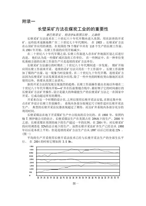
长壁采煤法在地下开采煤矿生产中占较高的百分比的。
在1980年,依照约翰T.博伊德公司的估计,长壁采煤法生产在美国占有20%地下的生产。
2000年之前,长壁采煤在美国的地下的生产超过一半的比例。
在2004年,对长壁采矿的应用调查是52%的总计地下的生产。
虽然长壁开采法矿井生产已经自从1998年以后是本质上平坦,但是连续的采矿方法生产自从1997以后已经衰退22% 。
采矿工程中的巷道掘进及支护分析摘要:对采矿工程的发展来讲,其实施的一大重要影响因素就是巷道的顺畅、高效挖掘。
实际的采矿企业必须加深对于巷道的掘进以及挖掘技术保障,由此提升工程实际质量。
本文探讨了采矿工程隧道掘进及支护技术,并分析了其在工程发展过程中的技术要点。
结合支护技术以及掘进技术发展,做好采矿作业安全质量保障。
关键词:采矿工程;巷道掘进;支护技术引言伴随着采矿业的不断发展,巷道掘进和支护技术已成为实际部门发展的一项基本技术。
在采矿工程发展过程中,相应的采矿人员必须了解到巷道掘进以及其施工的基本方法。
对支护技术做出充分了解,以此使得实际的巷道掘进支护能够相互配合。
保持施工步伐的一致,确保整个采矿工程保持其稳定性。
这样一来,实际工程质量也能够得到保障。
相应人员需认真分析采矿工程掘进和支护技术,对其内的某些危险点做好排除。
1采矿工程巷道掘进方法采矿工程中的巷道掘进方法有着很多,根据其决定方法不同,实际人员所能够采取的具体措施也是不同的,它们会出现不同的施工易难点。
根据其总体的决定程度来看,实际施工者必须对其施工方法做出考量。
首先,施工人员可以对施工过程做出了解。
采用一体化巷道掘进模式,通过大面积的决定方案了解其决定要点。
之后,再由某些机械化作业路途去优化其决定发展方案。
一体化巷道掘进在采矿工程中的应用是较为广泛的,此种方法都是基于采矿机或者决定其在系统研发的基础之上,通过大面积连续使用或者间隔使用方法来提供相互的支撑。
目前机械化巷道掘进手段已成为实际施工者采用的一种重要手段,与此同时,他们还要在掘进过程中考虑到各种除风、除尘设备。
了解到相应决定方法的应用,以此去保持巷道掘进过程的万无一失。
2采矿工程巷道掘进技术应用要点2.1瓦斯排放工作巷道掘进工作过程中的瓦斯排放是一项非常重要的工作,这不仅影响着掘进效率,更关乎着后期的安全问题。
相应的施工人员在决定过程中必须考虑到瓦斯的排放工作,对其各工作要点做出考量。
采矿工程巷道掘进和支护技术的应用分析发布时间:2021-10-14T06:13:48.487Z 来源:《工程建设标准化》2021年15期作者:薛源[导读] 近年来,经济快速发展,社会不断进步,煤矿产业为我国提供了大部分的能源薛源吉林省华林矿业集团有限责任公司摘要:近年来,经济快速发展,社会不断进步,煤矿产业为我国提供了大部分的能源,是我国社会发展的重要支柱,在采矿的过程中,随着挖掘工作的不断深入,矿底周围的巷道围岩和周围的环境会变得十分的复杂。
为了保证采矿的安全性,施工时都会对矿底的煤壁和顶板通过使用支护技术进行加固。
加固的合理性会直接影响到施工的安全性,一旦在掘进的过程当中支护不到位将会造成大面积的坍塌事故,不仅为施工单位造成了严重的经济损失,还影响到施工人员的生命安全。
本文主要是对巷道掘进和支护技术的应用进行论述。
关键词:采矿工程;巷道掘进;支护技术;应用分析引言我国经济与科学技术的发展,对矿产资源的需求不断增加。
煤炭作为重要的资源,是我国经济快速发展的主要能源之一,采矿行业在我国经济发展过程中起到了无法代替的作用。
为了能开采埋藏较大的煤炭资源,需要运用先进安全的科学技术,煤矿企业需要选择安全的巷道掘进技术以及矿井内部的巷道支护技术,以此保障人员的安全以及科学合理开采矿产资源。
1采矿工程专业巷道掘进技术在采矿工程专业巷道掘进行过程中,能够保证对钻眼工程爆破法的合理应用,在地底巷道工程施工做出整体规划与设计方案。
另外,能够保证采用几台钻探机来为工程施工项目服务。
并在工程施工时,对工程施工技术与施工计划保证考虑全面,从而促使炮孔深层掘进时顺利进行。
应用钻探机对巷道开展掘进时,理应融合矿带薄厚与炮孔间的间距来进行。
工程施工技术工作人员在早期设计平面施工图纸时,必须对掘进炮孔做出有效的整体规划与设计方案。
此外,还理应融合当场具体情况,对炮孔合理精准定位,另外保证合理遵循有关标准。
针对一般金属材料矿山企业层而言,沿脉与脉外巷道一样,特性时较为牢固,因此在掘进时,应采用单边掏槽的对策来进行。
采矿工程中的采矿技术及其施工安全采矿工程是指采取一定的方法将地下或地表上的矿石、矿砂等矿产资源从地下或地表取出来,并进行加工与利用的工程。
采矿技术是指在采矿工程中应用的一系列采矿方法、采矿设备以及采矿过程中遇到的问题解决的方法。
采矿技术在采矿工程中起到至关重要的作用,它的合理应用可以提高采矿效率、降低成本,并保障采矿过程中的安全。
下面将对采矿工程中常用的几种采矿技术及其施工安全进行介绍。
1.采矿技术:长壁采煤法长壁采煤法是一种常见的煤炭开采技术,它适用于大面积连续开采的煤矿。
采矿过程中,先在煤层下方开挖一条称为长壁的回采工作面,然后通过逐步推进回采工作面的方法,将煤矿从工作面上往下方推进,并及时进行支护。
施工安全:在长壁采煤法中,施工安全是关键问题。
工作面的推进速度不能过快,应根据地质条件和煤层结构来合理安排推进速度。
由于采煤工作面脚够推进,工作面后方的支护工作要跟上,以确保工作面的稳定和矿工的安全。
2.采矿技术:露天开采法露天开采法是一种适用于露天矿山的矿石开采技术。
它通常适用于开采矿岩体比较大、均质性好的矿石矿体。
开采过程中,首先将覆盖在矿石上方的表土和岩石剥离,然后使用机械设备将矿石露出,并进行运输和处理等后续工序。
施工安全:在露天开采法中,施工安全主要涉及岩体的稳定性和挖掘设备的安全操作。
矿山地质和水文条件要充分了解和评估,采取相应的岩体支护措施,以确保露天开采过程中不发生岩体滑坡、塌方等灾害。
机械设备的操作要求熟悉并遵守相关操作规程,确保人员安全。
3.采矿技术:深孔矿山法深孔矿山法适用于深埋地下的矿石矿体开采,主要是通过在地表钻探出一些垂直井眼,然后通过这些井眼进行矿石的开采和运输。
施工安全:深孔矿山法中的施工安全主要涉及井眼的支护和运输安全。
井眼的支护通常采用套管的方式,以确保井眼不坍塌和不受水泥混凝土沉浆腐蚀。
运输安全则需要严格控制运输设备的负荷和运行速度,避免运输过程中的事故发生。
长壁采煤条件下巷道三岔口有限元分析R.N. Singh, I. Porter, J. Hematian伍伦贡大学,工程学院,伍伦贡新南威尔士2522,澳大利亚摘要本文介绍了一个长壁开采三条巷道交叉口的三维有限元分析,并且评定了这种交叉口在一系列工况条件下的稳定/不稳定的范围。
载荷通过不均匀应力施加在模型的内部自由面。
这种从模型内部的加载方法有效的减小了尺寸效应并估计了边界效应。
梁的中截面、顶底和三角交叉口的连接状态和贯穿被计算。
基于此研究,提出了支护系统设计指导方针。
通过悉尼盆地的一个南部煤田的地下煤矿的三条巷道交叉口的现场实验对结果进行了严正,证明了结论的可行性。
2001年Elsevier Science B.V 版权所有。
关键词:地下煤矿;大断面巷道;交叉口;稳定性;有限单元法1.引言每年每层煤每个工作面生产3.0—4.0万吨煤存在于澳大利亚现有的高效长壁工作面中。
这种成功主要在于高产的长壁工作面能在生产期间保证巷道和交叉口的稳定性同时达到高效率的工作。
当两条巷道交错到一起时,掘巷机开切眼掘出巷道交叉口。
地下煤矿巷道交叉口和地面固有的宽顶板宽度相比具有独特的影响因素,存在在高度机械化程度下安装顶板支护困难的问题。
应力诱导的交叉口变形可以导致顶板下沉和断面冒落。
很多人(Chudek et al., 1983; Taber and Grenney, 1995;Eckoff and Braverman, 1996)在大断面交叉口方的稳定性方面进行了研究,认为是像来自移动的长壁工作面的高水平应力和不稳定的支承压力等不利的条件的结果。
例如在1985年,在西部煤矿6号工作面的主要大巷的岩层控制问题导致顶板下沉,使得煤矿的生产不得不停了6个星期。
同样,太平洋煤矿的顶板冒落导致长壁工作面设备被埋,以至于工作面停产3个月(Ruston et al., 1988)。
因此,在高效地长壁生产系统中空前的岩层控制意义在于长期而并非短期。
用于采矿工程的有限元与边界元耦合方法及程序
张国联;解世俊
【期刊名称】《矿山技术》
【年(卷),期】1990(000)006
【总页数】3页(P28-30)
【作者】张国联;解世俊
【作者单位】不详;不详
【正文语种】中文
【中图分类】TD8
【相关文献】
1.刚粘塑性有限元——边界元耦合方法在模拟板材热(连)轧过程中的应用 [J], 姚成保
2.边界元——有限元耦合方法分析 [J], 张效松
3.流-固耦合问题边界元-有限元耦合方法分析 [J], 张效松;叶天麒
4.Navier-Stokes方程的有限元边界元耦合方法 [J], 何银年
5.非连续边界元-有限元耦合方法分析 [J], 张效松;叶天麒
因版权原因,仅展示原文概要,查看原文内容请购买。
翻译部分英文原文Finite element analysis of three-way roadway junctions inlongwall miningR.N. Singh, I. Porter, J. HematianFaculty of Engineering, UniÍersity of Wollongong, Northfields Avenue,Wollongong, NSW 2522, AustraliaAbstract:This paper presents a three-dimensional finite element analysis of three-way roadway intersections in longwall mining, and assesses the stable/unstable behaviour of three-way intersections under a range of loading conditions. Loads were applied to the model by means of uniform stresses on the internal free faces. This method of loading the model from the inside helped to reduce its size and to eliminate the boundary effects. Stress concentrations and displacement results on the mid-height of the pillars, roof and floor strata adjacent to the three-way intersections and cut-throughs were calculated.Based on this study, guidelines for designing the support system for three-way intersections are suggested. The results were validated by a case study of a three-way intersection in an underground coal mine in the southern coal fields of the Sydney Basin.Keywords:underground coal mining; gate roadway; intersections; stability; finite element method1. IntroductionA trend exists in Australia for installing high productivity longwall faces producing 3.0~4.0 milliontonne raw coal per annum per face. The mainconcern for the success of the high-production longwallfaces is to achieve high rates of developmentand to maintain stability of access roadways andtheir intersections during the life span of the face.Intersections are formed when the pillars betweenthe two roadways are intersected by driving a crosscut. Roadway intersections in underground mines areparticularly susceptible to ground control problemsdue to inherently wide roof spans used and the difficulty in installing roof supports promptly inhighly mechanised headings. Stresses induced duringintersection formation may result inhigh incidenceof roof and rib failures. Despite many investigationsinto the stability of gate roadways intersectionsadverse conditionssuch as high horizontal stress and unsteady state ofabutment pressure from moving longwall faces maycause instability of gate roadway intersections.For example in 1985; major strata control problems inthe main gate of no. 6 longwall panel at WestcliffColliery resulted in roof fall, which stopped coalproduction for a period of 6 weeks. Similarly, a rooffailure incident at Pacific Colliery caused the longwallequipment to be buried resulting in stoppage ofthe longwall operations for a period of 3 months.Thus, unprecedented stratacontrol problems may have significant effects onoverall production from high-productivity longwallsystems even over a short duration.This paper containsan investigation of the application of a three-dimensionalfinite element method to calculate stressesand displacement around three-way roadway intersections.The effects of individual parameters such as depth of cover, the ratio of horizontal to verticalstress (K) and the width of opening on the stability of the three-way intersections are examined. Theresults are compared with the field observations at anunderground coal mine in the southern coal field ofthe Sydney Basin.2. Stability analysis of three-way intersections using three-dimensional finite element modelsThe procedure used in the stability analysis of thethree-way intersections comprised of defining themechanical properties of the rocks surrounding theintersection, the geometry of the intersection and thevirgin state of stress. The stresses and displacements induced around the intersections were computed usinga three-dimensional finite element method. Ifunstable conditions existed, either the design of supportsystem was changed or the geometry of thestructure was modified.Important input data forthese models were vertical stress and the ratio ofhorizontal to vertical stress K for a given lithologyand dimensions of the roadway intersection .Assuming symmetrical conditions around a threewayintersection, only half of the structure wasmodelled using eight-node solid elements comprisinga total of 7190 elements and the 11 597 grid points.The computer running time was 17 h using around 1Gb of memory. The rock mass properties assigned tothe intersection model are presented in Table 1.The loads were applied to the model by means ofuniform pressures on the internal free faces. Thistechnique of applying load from the inside helped to reduce the size of the model and to eliminate boundaryeffects. For all the loading configurations depictedin Table 2, a linear solution method was used.Preliminary computer analysis was carried out tocompute the induced vertical stress distributionthroughout the three-dimensional model for a litho-staticcondition. In order to gain better understandingon the behaviour of the structure, the vertical stressconcentration on various horizontal and verticalplanes was shown for different loading conditions byplotting stress concentration contour lines for variousratios of induced virgin stresses. These results are discussed in the subsequent sections.3. Pillar behaviour at three-way intersectionFig. 2 indicates vertical stress concentration at themid-height of the pillar for various loading configurations.For the litho-static stress condition at K=K x=K y=1, the stress concentration at the midheight of the pillar has a symmetrical pattern (see Fig. 2a). The stress concentration zone on the ribside of the intersection has a width of 2.5 m, equal tohalf the roadway span. The maximum stress concentrationis about 1.4 times the virgin stress for theloading configuration K y>1 for a limited zone at the corner of the pillar.When K y >1, the vertical stress pattern at the mid-height of the pillar is no longer symmetrical;thestress is more pronounced along the roadway perpendicularto the direction of maximum horizontal stress(see Fig. 2b).No tensile zone along the rib side wasdetected. The maximum stress concentration zone islocated close to the edge of the pillar and extends along the roadway perpendicular to the major horizontal stress.4. Roof behaviour at three-way intersectionThe vertical stress distribution on a plane 1.5-mabove the roof line is shown inFig. 3, which indicatesthat the stress is 0.8z σ over the edge of pillar increasing to 1.0z σ at a distance of 6 m within the edge of the pillar. The stress distribution lines abovethe individual roadways show the contour lines atintervals of 0.2z σ.This stress distribution pattern indicates a semi-dome shaped destressed zone overthe three-way intersection. When the ratio of horizontalto vertical stress, K x or K y increases, the stress contour line 0.2 z σ moves towards the centre of the roadway while 1.0z σ line moves further into the pillar indicating that the height of the semi-domeshaped destressed zone becomes shallower in thefield of high horizontal stress.When K x ≠K y , as shown in Fig. 3b, the stresspattern varies over the individualroadways and 0.2z σpartly disappears in the roadway perpendicular to themajor horizontal stress. In this case, the boundary ofthe roof fall in this roadway will be controlled by thestress contour lines of 0.4z σ .However, the rate of changes in stress distribution across the roof line ofthe roadway parallel to high horizontal stress is moresignificant. The height of the roof fall in the roadwayintersection might be evaluated by using appropriatedestressed contour lines on the vertical plane at themid-span of the main roadways and the cut-throughs,respectively, as presented in Figs. 4 and 5. Thejustification of using 0.4z σ contour line to delineate the boundary of roof fall is presented in a subsequentsection.Fig. 5 Vertical stress concentration on the vertical plane at the mid-span of thecut-through.Fig. 5 also indicates that the radius of influence ofthe intersection over theindividual roadways with respect to the stress distribution in the roof is estimatedto be one span from the centre of the intersection.Fig. 6 shows the vertical displacement on the roofline under various loadingconfigurations at the roadwayintersection. The maximum sag occurs at the centre of the intersection and its maximum value is12 mm. It can also be seen that the roadway parallelto the major horizontal stress will show more roofsag than the roadwayperpendicular to the horizontalstress.Behaviour of the floor at the T-junction of athree-way intersection is given in Fig.7 on the floorline for loading configuration K x=1 and K y=2. The floor lift patterns are similar to that of the roofsag except that the amount of the maximum floorheave is much less than the corresponding value forsag.5. Case history of three-way intersectionsAn investigation into the mechanism of instabilityat roadway intersections was carried out at tail gatesof a longwall panel in an underground coal mine inthe southern coal fields of the Sydney Basin. Thefield measurements included roof sag, floor heaveand rib deformation monitoring ahead and behind thelongwall face. The overall objective of this studywas to validate the results of three-dimensional finiteelement modelling of the three-way junction by comparingthe results with the field measurements.5.1. Site location and the description of the site-specific ModelFig. 8 presents the details of the longwall panel, gate roadways and intersections at the site beinginvestigated. The panels were 200-m wide and 2000-m long with a double entry gate roadway system.Each roadway was 5 m wide, 3 m high, with 55×40 m pillars centre-to-centre. The height of extractionvaried between 2.4 and 2.6 m.The actual sites ofmonitoring were 35, 36 and 9 intersections of 24longwall’s tail gate and 35 and 36 cut-throughs. Thevertical stress at the site was 10 MPa at the depth of420 m, the major horizontal stress 25 MPa orientedparallel to the gate roadways andthe minor horizontalstressThe mechanicalproperties of the strata units are shown in Table3. Based on the above information, a number ofthree-dimensional finite element models were constructedand analysed to simulate the existing conditionsaround the sites of investigation. Both inducedstresses and displacements around the roadways andintersections were computed for each site of investigation. The results of the finite element analyses arepresented together with the values obtained from thefield displacement measurements.A series of roof, rib and floor extensometers were installed at and in between 35,36 and 9 cut-throughsahead of 23 longwall panel. The objective of thisstudy was to determine the pattern of deformationaround the area of investigation and provide a measureof ground control. The extensometers site andlocation for principle modes of failure are also presentedin Fig. 8.The roof sag measurements have been carried outat different locations and compared with values predicted by the finite element model.In all cases,Table 3 Mechanical properties of rock at the site of investigationThe differences between the measured and predicted values are very small. Fig.10 indicates typical results of roof sag measurements, together with the predictedvalues of displacements at 9 cut-through, before andafter the longwall face has passed through the monitoringsite.Monitoring continued when the longwallface approached and passed 9 cut-through andreached the end of the panel. Readings were regularlytaken over a period of 45 days, but for the sakeof simplicity, only the initial and final readings areshown.It can be noted that the difference betweenthe initial and final readings was very little. Therefore, it can be concluded that the time dependentdeformation of the roof was very little. In addition,visual examinations indicated that good roof conditionsprevailed throughout the investigation without displaying any strata softening and roof paring the results of deformation at 9cut-through before and after longwall no. 23 passedthe site, it can be seen that tailgate behaviour issignificantly affected by the retreat of the adjacent face.5.2. Rib behaviourThe results of rib extensometers and those predicted by the finite element analysis are presented in Fig. 11. The results indicate a timedependent deformation of 0.4 mm dayy1. As thetime dependent behaviour of the coal seam could notbe modelled in the finite element analysis of thestructure, the predicted values are only the totaldeformation after complete relaxation and thereforeless than the measured values.The important aspect of the chain pillar between35 and 36 cut-throughs is the nature of the ribmovement. The extensometer readings indicate thatthe softening has occurred to a depth of 5 m. This isin contrast to rib behaviour observed at 9 cut-throughwhere the deformation into the pillar rapidly abatesfrom the rib line.5.3. Floor behaviourThe floor extensometers results and the displacementvalues predicted by the finite element method at 35 cut-through are presented in Fig. 12. The plotindicates that although the deformation initiated 5 mbelow the floor surface, the majority of deformationtook place between 1.0 and 1.5 m into the floor.Thus, floor heave takesplace in the broken shale andthe laminated shale units as referred to in the lithologyprofile presented in Fig. 9. Although the shaleunit is surrounded by the laminated sandstone/shale,it can generate an uplift stress in the immediate floorwhen failure occurs within it. The significant floorheave at 9 cut-through is mainly attributed to thehigh horizontal stress and the side abutment stress ofthe longwall face.It has been previously demonstrated in an earlierpublication by the present authors that roadways parallel to the major horizontalstress, where K (K x or K y ) > 1, will have greaterfloor heave and roof sag when compared to road-ways parallel to minor horizontal stress.6. Guidelines for designing the support system at three-way intersectionsThe results of investigation of three-way intersectionsshowed that the maximum vertical stress at themid-height of the coal seam occurs at the corner ofthe pillar and increases with the roadway width andthe depth below surface. The destressed zone overthe pillar extends along the roadway perpendicular to the major horizontal stress.A uniform pattern ofhorizontal dowels in conjunction with wire meshwould be necessary to ensure the integrity of thepillars. A minimum dowel length equal to 50% ofthe entry width at 1.0-m spacing is suggested. Thispattern should be implemented on the edge of thepillar extending along the roadways for a distanceequal to one roadway span. The rest of the pillars inthe individual roadways should be reinforced if necessaryaccording to single roadway conditions.The four potential modes of failure should betaken into account when designing the optimum roofbolt pattern at three-way intersections.The first zoneof instability may manifest itself as a semi-domeshaped failure over the T-intersection. One side ofthe zone is parallel to the left of the main roadwaywith the base being a semi-circle. When K x ≠K y the base of the zone will have a different length ineach roadway, with the longer length perpendicularto the major principle horizontal stress. Although theproperties of the roof strata have significant effect onthe stability of the roof, the stress contour lines 0.1z σand 0.3z σ have been used to define the boundary of the roof failure zone above the three-way intersectionfor K x or K y <2 and K x or K y > 2, respectively However, observations at two field sites in theSouthern Coalfield and Hunter Valley have indicatedthat the height of roof falls is generally governed bythe regional stresses, in particular, the ratio of horizontalto vertical stress, the width of the openingsand mechanical properties of the overlying strata.Previous observations at site 2 in Hunter ValleyCoalfield by one of the authors have indicated thatthe height of roof falls matched very well with thearea under stress contours of 0.3z σ. Therefore, in order to be on a conservative side, a stress contour of 0.4z σwas adopted as a criterion for roof fall height in the present study.The second mode of failure is due to shearingalong the bedding planes, which occurs when theshear stress exceeds the frictional strength of thebedding planes.The most probable location for slidingof bedding planes occurs closer to the rib sidethan to the roadway centre. The required length ofthe fully grouted bolts depends upon the cohesion, the coefficient of internal friction and the location ofthe bedding planes. Thus, a general roof bolt pattern cannot be devised for all conditions and an accurateanalysis of site-specific models based on the accuratefield data is necessary.The third potential mode of failure is gutteringalong and over the rib sides and corners of theintersection. This is more likely to happen when thehorizontal stress is greater than the vertical stress.Inclined roof bolts passing through this zone andanchored over the pillars are a possible solution.The fourth mode of failure is controlled by thepresence of a geological feature in the intersection.When a major geologically weak zone is present inthe area of the intersection, the roof instability ishighly influenced by the structural feature. In thatcase, the prediction of the roof fall would be governedby the orientation and inclination of the geologicalfeature, internal angle of friction and dimensionsof the intersection. In that case, a specialsupport measure will be required to ensure stability.The three-way intersections cause specific stratadisturbances in the vicinity and can be convenientlydivided into two zones as indicated in Fig. 13. Inregion I, which is outside the zone of intersection, the roof condition is the same as in main roadways.Therefore, roof support is carried out based on theprocedure for individual roadways. Region II, whichis within the roadway intersection, experiences increasedstrata loading and therefore special adjustmentto roof bolt length and location must be considered.The roof bolt length must be increased by 50%and the spacing reduced by 25% in comparison tothe bolts in region I. The load carrying capacity ofthe bolt must be calculated according to height of thedestressed zone. It is suggested that in high horizontal stress fields, the roadways running parallel to thehigh horizontal stress must be driven first and thesupport for the completed intersection must be installedbefore the other roadway is inter-connected.Itis also suggested that the installation of inclined roofbolts near the rib and use of w-straps parallel to thepillar edge would help in maintaining structural stabilityof the three-way intersection.7. General discussion and conclusionsDrivage conditions can be significantly influencedby the orientation of roadways with respect to themajor horizontal stress, the effect of side abutmentpressure due to longwall extraction and the presenceof soft strata in the floor. Field investigation indicatedthat the drivage conditions parallel to the majorhorizontal stress were goodwith minimum roof shearfailure.In contrast, the drivage perpendicular to themajor horizontal stress displayed considerable shearzones particularly at locations close to the intersections.An increase in the stress magnitude due to thepresence of geological structures accentuated theshear failure.These situations were well illustratedand predicted during the finite element analysis ofroadways and intersections undervarious configurations and stress regimes.Due to a number of reasons, there are still somedifference between the field measurements and thefinite element model results.Uncertainty regardingthe in situ properties of the strata units, stress regime, the presence of geological discontinues and geologicalstructures may be some of the reasons for thisdiscrepancy. Moreover, lack of consideration to thetime dependent properties of the rock mass anddynamic loading resulting from an approaching longwallface may further contribute to the lack ofaccuracy.This paper contains a successful demonstration ofthe application of the finite element method to thestability analysis of three-way intersections.In general,the significant agreement achieved between thefield measurements and the FE results have provedthat the FEM can be successfully used for the stabilityanalysis of underground structures.Results of investigations on the stability of threewayintersections showed that the general stress and displacement patterns around the three-way intersectionsare the same as in four-way intersections butpresenting less severe instability problems 。