英国阿尔法Alphasense硫化氢传感器 H2S-A1
- 格式:pdf
- 大小:197.38 KB
- 文档页数:2
硫化氢检测仪的使用方法
硫化氢检测仪通常是用于测量空气中硫化氢(H2S)浓度的仪器。
以下是一般的使用方法:
1. 准备:确保仪器已经经过校准并处于工作状态。
检查传感器是否完好,并确认电池电量足够。
2. 设置:根据需要,设定测量单位和报警阈值。
一般来说,硫化氢检测仪会配备一个液晶显示屏,可以用按钮或旋钮设置相关参数。
3. 打开仪器:按下开关按钮或旋转开关,打开检测仪。
4. 预热:检测仪通常需要一段时间进行预热,以确保传感器的准确测量。
等待预热完成。
5. 进行测量:将检测仪的传感器暴露在待测空气中,可以通过吸气泵或直接靠近气体源进行检测。
等待一段时间,直到测量结果稳定并显示在屏幕上。
6. 结果读取:读取屏幕上显示的硫化氢浓度值。
确保浓度值在安全范围内。
如果超过设定的报警阈值,仪器可能会发出声音或光闪烁以示警告。
7. 关闭仪器:使用完毕后,按下关闭按钮或旋转关闭开关,将检测仪关闭。
注意事项:
- 在操作过程中,确保按照仪器的说明书进行正确、安全的操作。
- 确保仪器定期校准,以保证测量结果的准确性。
- 使用仪器时,应遵循相关的安全操作规程,戴好个人防护装备。
- 如果检测到空气中硫化氢浓度过高,应采取必要的措施确保人员安全,如迅速撤离危险区域并报警。
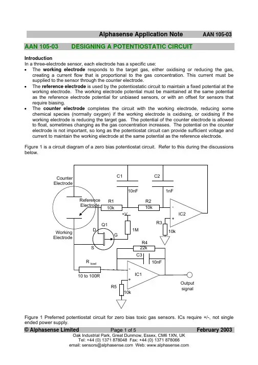
AAN 105-03DESIGNING A POTENTIOSTATIC CIRCUITIntroductionIn a three-electrode sensor, each electrode has a specific use:• The working electrode responds to the target gas, either oxidising or reducing the gas, creating a current flow that is proportional to the gas concentration. This current must be supplied to the sensor through the counter electrode.• The reference electrode is used by the potentiostatic circuit to maintain a fixed potential at the working electrode. The working electrode potential must be maintained at the same potential as the reference electrode potential for unbiased sensors, or with an offset for sensors that require biasing.• The counter electrode completes the circuit with the working electrode, reducing some chemical species (normally oxygen) if the working electrode is oxidising, or oxidising if the working electrode is reducing the target gas. The potential of the counter electrode is allowed to float, sometimes changing as the gas concentration increases. The potential on the counter electrode is not important, so long as the potentiostat circuit can provide sufficient voltage and current to maintain the working electrode at the same potential as the reference electrode. Figure 1 is a circuit diagram of a zero bias potentiostat circuit. Refer to this during the discussions below.Figure 1 Preferred potentiostat circuit for zero bias toxic gas sensors. ICs require +/-, not single ended power supply.© Alphasense Limited Page 1 of 5 February 2003A typical potentiostat circuit consists of three parts:1 Control circuit with bias voltage, if required2 Current measuring circuit3Shorting FET to connect the working electrode to the reference electrode when power is off Control CircuitThe control op amp (IC2 in figure 1) provides the current to the counter electrode to balance the current required by the working electrode.The inverting input into IC2 is connected to the reference electrode and must not draw any significant current from the reference electrode. An op amp with an input bias current of less than 5nA is recommended.When switching on the circuit, the depletion mode JFET (Q1 in Fig 1)goes to a high impedance state and IC2 provides the current to maintain the working electrode at the same potential as the reference electrode. Any offset due to the input offset voltage in IC2 will therefore cause a sudden shift in potential at switch-on. Toxic gas sensors have a large capacitance, so significant currents can flow for small potential shifts, so ensure that your op amp has a low offset voltage, certainly less than 1 mV and preferably less than 100µV; also check the op amp offset voltage at the maximum usage temperature.Typically, for an oxidisable gas (such as CO) with a platinum reference electrode, the counter electrode will be -300 to -400mV from the ground potential. However, if hydrogen ions rather than oxygen molecules are reduced, then the potential could be as large as -1.05V. Also, reducing gases (such as NO2 or Chlorine) force the counter electrode to oxidise water, evolving oxygen; in this case the potential relative to the reference electrode is between +600 and +800 mV, depending on the type of reference electrode. Therefore, you must allow IC2 enough voltage swing to drive the counter electrode to the required potential and with sufficient current demanded by the sensor. If the circuit is unable to do this, then extreme non-linearities will occur at higher concentrations. It is best to allow ±1.1V swing on IC2 (plus any imposed bias voltage). This means that for a CO or H2S sensor the counter electrode wants to be typically -350 mV below the ground point, so IC2 needs a negative supply. If you are using a single ended low voltage power supply, pay particular attention to the available output swing on the op amp at the required current.Table 1 below shows the maximum generated steady state current for each type of sensor. At full scale no sensor generates more than 210µA, but allow at least 500µA for a general purpose circuit, although this can be decreased for specific, well tested sensor/ circuit combinations. Beware- when switching the circuit ON in the presence of an electroactive gas or when a new sensor is first connected, the sensor may give a surge current of several mA that may cause IC1 to clamp, depending on the current drive capacity of IC1; it is unlikely that IC1 can maintain the virtual earth on its inverting input with a high feedback resistor during such a high current transient. Always connect the sensor before powering the circuit.Circuit stability and noise reduction in the control circuit relies on R1, R2, C1 and C2; C2 may not be necessary for certain op amps. If eliminating C2, then C1 may be increased- between 10 and 100 nF. Suggested op amps are OP90 (single op amp) and OP 296 (dual op amp).© Alphasense Limited Page 2 of 5 February 2003Bias voltageNormally, Alphasense toxic gas sensors are operated in the zero bias mode; however, certain sensors, such as NO sensors, require a bias voltage: typically ±150 or 300mV for an NO sensor. Alternatively, sensor cross-sensitivity to certain gases can be enhanced by adding a bias voltage.BEWARE! performance can also be degraded if you bias incorrectly! Remember that biasing a normally unbiased sensor may damage the sensor and certainly voids the sensor warranty. Consult Alphasense for further advice.If you wish to inject a bias voltage then also ensure that your bias voltage is stable: changes of even a few mV can affect sensitivity to gases and rapid changes in the bias voltage by only a mV will generate transient effects for up to hours on the sensor output. A simple method of biasing the sensor is shown in figure 2 below. The 10K load resistor to ground can be removed to reduce the current on V bias.Biasing should be maintained when the instrument is switched off - this is normally accomplished by using a button cell battery that remains on at all times. In this case, the input offset of IC2 is not critical, but its drift with temperature etc. must be kept small.Current Measuring CircuitThe measuring circuit is a single stage op amp (IC1) in a transimpedance configuration; the sensor current is reflected across R4, generating an output voltage relative to the virtual earth. C3 reduces high frequency noise. It is sometimes desirable to use two opamp stages to give the required output; the first stage should use a low value for R4 to allow the circuit to oppose the sensor current in transient conditions, followed by a second voltage gain stage to give the required output. The input offset voltage of IC1 will add to the sensor bias voltage (as the working electrode will be offset from 0V) so the input offset should be kept low. Remember that the generated current can be either positive or negative: sensors that oxidise at the working electrode (e.g. CO) generate a © Alphasense Limited Page 3 of 5 February 2003current into IC2, while reducing working electrodes (e.g. Cl2 or NO2) sink a current. So for the second case, ensure that IC2 has adequate current sinking capability.The measuring circuit uses a combination of the (load resistor (R load) plus internal sensor resistance) and the (internal sensor capacitance) to establish an RC circuit; the selection of R load is a compromise between fastest response time (low resistance R load) and best noise (high resistance R load): this RC circuit affects both the rms noise and the response time: the response time increases linearly with increasing R load resistance, while noise decreases rapidly with increasing R load resistance. If you need highest resolution, then forfeit fast response time. Likewise, if fast response time is critical, then reduce the resolution of your display or sample the signal faster and average over several readings in software to eliminate jitter. Due to the low impedance nature of the circuit, it is better to use an opamp with low noise current (usually at the expense of noise voltage)to get the best overall noise performance.As sensor current flows through R load, there will be a small change to the sensor bias potential. This has the effect of increasing the sensor settling time as the sensor will require a short time to re-stabilise when gas is applied, but this transient will normally not be seen except at high gas concentrations and high R load resistance.Refer to Table 1 below to calculate the required gain for your measuring circuit. If your detector/ instrument does not use the full scale of the sensor, then simply multiply the Sensitivity by your Range to determine the maximum current from the sensor. Since the sensitivity is the typical value, allow 20% more than the typical full scale output into your A/D converter.Sensor FullScale(ppm)Sensitivity(nA/ppm)(typical)Full Scaleoutput(µA)Full Scaleoutput(V)Calibrationpoint(ppm)CO-BF, CO-B1, CO-BX1,000100100 1.00 400 CO-AF1,00070700.70400 CO-AX2,00065130 1.30400 CO-AE 10,00030300 3.00 2,000 CO-DF1,00040740.74400 H2S-AH 501,200600.60 20 H2S-BH502,000850.8520 H2S-A1 100750750.75 20 H2S-B1200370740.7420 H2S-BE2,00090180 1.80 400 H2S-AE2,000105210 2.10400 H2S-D1100140140.1420 SO2-AF20500100.10 20 SO2-BF100350350.3520 SO2-AE2,00070140 1.40400 NO2-A1 20-3508-0.08 10 NO2-B120-75022-0.2210 NO2-AE200-35070-0.75100 NO-A1,-B1250400100 1.0050 NO-AE1,000100100 1.00400 Cl2-A120-3708-0.0710 CL2-B120-900220.2210 Table 1. List of output parameters and calibration point for Alphasense toxic gas sensors.© Alphasense Limited Page 4 of 5 February 2003Shorting FETIt is normal practice to add a shorting FET for unbiased sensors so that the reference and working electrodes are shorted together (with a residual resistance of a few tens of ohms) when power is removed from the circuit. This ensures that the working electrode is maintained at the same potential as the reference electrode when the circuit is switched off. The shorting FET is normally open circuit as long as power is applied. This “zero bias” state ensures that when you switch the circuit back on, the sensor is ready immediately. If you do not use a shorting FET and leave the sensor open circuit when the circuit is off, the toxic gas sensor will take a few hours to stabilise when next switched on.If you are supplying a bias voltage through IC2, then when you switch off the circuit, the sensor will be zero biased and hence when you reapply a bias voltage it will take a significant time (up to several hours) for the sensor to re-establish equilibrium. It is recommended that, for biased circuits, the bias voltage be maintained on at all times and the shorting FET not used. This will not affect the operating life of the sensor.The JFET (Q1) should be a p-type FET. Recommended FET types include surface mount or TO-92 packages as per Table 2 below.Manufacturer Product Code TypeSiliconix SST177Surface MountSiliconix J175TO-92Siliconix J176TO-92Siliconix J177TO-92Fairchild J175TO-92Table 2. Recommended p-FETs for short circuiting reference and working electrodes when the potentiostat circuit is off.Noise, RFI/EMI ScreeningIdeally, the measuring and controlling op amps in a potentiostat are fitted directly underneath the sensor to keep the shortest leads because of the low impedance and low sensor currents. Alphasense Application Note AAN 103 gives further advice on reducing noise and improving RFI/EMI screening.Sensor CalibrationNote that toxic gas sensor sensitivities are variable,typically ±15%. So you must calibrate in software to correct for sensor-to-sensor sensitivity variations. Alphasense maintains a database of the sensitivity of every sensor tested at Alphasense, but remember that sensitivity will drift downwards with time, typically 0.5% to 2% per month, depending on the sensor type, relative humidity and gas concentration/ temperature conditions. See Application Note AAN 108 for more information.It is also normal to correct for temperature dependence of the sensitivity; zero current is not normally temperature corrected, but for measurements requiring high accuracy at low concentrations, contact Alphasense for advice.© Alphasense Limited Page 5 of 5 February 2003。
硫化氢气体检测仪工作原理分析介绍硫化氢气体检测仪是一种可用于检测空气中硫化氢浓度的仪器设备。
由于硫化氢是一种臭鸡蛋味的有毒气体,容易引起人体中枢神经系统的损伤和死亡,因此,硫化氢气体检测仪在化工、制药、环保等工业领域使用得非常广泛。
本文将会从硫化氢气体检测仪的工作原理进行分析。
硫化氢气体检测仪的工作原理硫化氢气体检测仪的工作原理主要基于双极性半导体传感器,采用了化学传感技术。
传感器的灵敏度随着气体浓度的增加而不断提高。
传感器可以在不同的温度下工作,使它们更加适用于不同的工业环境。
下面是硫化氢气体检测仪的详细工作原理:1.空气搜集器首先,空气被搜集器中的泵子吸入,经过滤网和冷却器,完全去除较大的杂质颗粒,并降低空气温度,以确保空气纯净度和检测精确度。
由此得到的空气,将会和燃料气体以非稀释方式混合在一起。
2.燃料电极搜集器中的混合气体被输送到燃料电极上,与燃料电极上的电化学反应发生,使得燃料电极上形成一定浓度的氢离子(H),如下所示:H2 + 2e- -> 2 H+3.检测电极检测电极由双极性半导体材料构成。
由于检测电极与燃料电极之间的距离非常接近,当氢离子(H)与空气中的硫化氢分子(H2S)相互作用时,会产生一定的电信号,并通过检测电极上传到微处理器中进行反馈处理。
4.反馈处理微处理器将检测到的信号进行反馈处理,得到空气中硫化氢的浓度,以及相关的报警信息。
当检测到空气中的硫化氢浓度超过一定的阈值时,硫化氢气体检测仪将立即发出声音和光线警报,通知用户先行撤离。
总结本文从硫化氢气体检测仪的工作原理进行了详细分析。
硫化氢气体检测仪的工作原理主要基于双极性半导体传感器,采用了化学传感技术。
通过合理的空气搜集、燃料电极和检测电极的结构设计以及微处理器的反馈处理,硫化氢气体检测仪实现了对空气中硫化氢浓度的监测和报警。
硫化氢气体检验方法
硫化氢(H₂S)是一种有毒气体,因此需要进行检测以确保环境和工作场所的安全。
以下是一些用于检测硫化氢气体的常见方法:
1.传感器检测器:这是最常见和便捷的检测方法之一。
传感器检
测器通常是手持式的,可以携带到需要检测的地方。
这些检测
器使用化学传感器或电化学传感器,可以快速、准确地检测硫
化氢浓度。
一些传感器检测器还可以提供声音或视觉警告以示
警报。
2.气体检测管:气体检测管是一种使用简便的检测方法,通过颜
色变化来指示硫化氢浓度。
用户将一端打开,将其置于待检测
气体中,通过观察管内试剂颜色变化来判断气体浓度。
3.气体检测仪器:高级的气体检测仪器通常用于长期或定期的气
体监测,尤其在工业环境中。
这些设备可以实时监测硫化氢浓
度,并记录数据。
一旦浓度超过设定的安全水平,检测仪器将
发出警报。
4.固相吸附管:固相吸附管是一种简单但有效的气体检测方法。
用户将吸附管置于空气中,硫化氢会被吸附到管中的吸附剂上。
然后,用户将吸附剂送到实验室进行分析,以确定硫化氢浓度。
5.颗粒计数器:这是一种检测空气中硫化氢颗粒浓度的方法。
颗
粒计数器使用激光或其他技术来计算颗粒数量,从而确定硫化
氢的浓度。
在进行硫化氢气体检测时,务必遵循安全操作规程,并使用经过校
准和合格的检测设备。
如果在工作中发现高浓度的硫化氢,必须立即采取适当的措施,例如通风或撤离,以确保工作环境的安全。
硫化氢传感器:一项重要的环境保护技术近年来,环境保护已经成为了全球各国政府和民间团体的热点话题。
随着工业化和城市化的快速发展,大量的有害气体和化学物质排放给环境带来巨大的威胁。
其中,硫化氢被认为是一种高度有害的气体,对人类身体健康和自然生态环境都带来了不可避免的危害。
为了有效地控制和减轻硫化氢对环境的影响,的研发和应用显得尤为重要。
一、的基本原理是用于检测并 quant 转硫化氢浓度的一种设备。
通常工作于一定的温度、湿度和大气压等条件下。
它们的基本结构通常由传感元件、放大器、显示器和控制电路等部分组成。
传感元件一般采用半导体、电化学或红外光学等不同的技术,它们具备不同的检测速度、灵敏度和电子学特性。
其中,半导体是一种最常见的传感器,它是用玻璃或石英管封装一个半导体材料,通过半导体材料与空气接触并发生化学反应,从而测量硫化氢浓度。
电化学则是采用电化学原理测量硫化氢气体的浓度,它们的精度和灵敏度一般比半导体高。
红外线则是利用硫化氢特殊的吸收光谱进行测量,测量精度比较高且对其他气体的干扰较小。
目前研发中的微机电系统(MEMS)具有更高的灵敏度和稳定性。
二、的应用范围硫化氢被广泛应用于生物制造、化学工业、碳化物制造、纺织加工、食品加工、医疗废物处理等领域。
在饲养场等生产领域中,硫化氢是由动物粪便、糞尿、沼气等发酵物质释放出来的。
在化工和制药工业中,硫化氢是生产过程中常见的废气之一。
硫化氢气体浓度高、味道难闻、易燃易爆,如果时间长、浓度过高的话,会对人体、环境产生非常严重的危害。
应用得相当广泛,主要目的是用于环保、安全、减少人力、物力资源浪费等。
以生产领域为例,可以用于检测饲养场的沼气,从而有效地控制有害气体的排放,保护当地生态环境。
在化工和制药工业中,可用于检测和控制生产过程中的硫化氢排放,避免对员工身体健康和环境的影响。
此外,在卫生保洁、医疗等方面,也有着广泛的应用。
三、的发展前景在全球环保政策的倡导下,已经被广泛应用于各个领域。
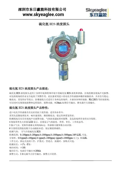
硫化氢H2S浓度探头硫化氢H2S浓度探头产品描述:硫化氢H2S浓度探头适用于各种环境和特殊环境中的硫化氢H2S浓度和泄露,在线检测及现场声光报警,对危险现场的作业安全起到了预警作用,此仪器采用进口的电化学传感器和微控制器技术,具有信号稳定,精度高,重复性好等优点,防爆接线方式适用于各种危险场所,并兼容各种控制器,PLC,DCS等控制系统,可以同时实现现场报警和远程监控,报警功能,4-20mA标准信号输出,继电器开关量输出。
硫化氢H2S浓度探头产品特性:进口电化学传感器具有良好的抗干扰性能,适用寿命8年。
采用先进微处理技术,响应速度快,测量精度高,稳定性和重复性好。
检测现场具有具有现场声光报警功能,气体浓度超标即时报警,是危险场所作业的安全保障。
4现场带背光大屏幕LCD显示,直观显示气体浓度,类型,单位,工作状态等。
5独立气室,更换传感器无须现场标定,传感器关键参数自动识别。
6全量程范围温度数字自动跟踪补偿,保证测量准确性。
检测气体:空气中的硫化氢H2S检测范围:0~100ppm,0~200ppm,0~1000ppm,0~1000ppm,0~5000ppm,100%LEL可选。
分别率:0.01ppm(0~100ppm);0.1ppm(0~1000ppm);1ppm(0~10000ppm以上);0.1LEL.工作方式:固定式连续工作,扩散式,管道式,流通时,泵吸式可选。
检测误差:≦1%(F.S)响应时间:≦10S输出信号:电流信号输出4-20MA报警方式:2路无源节点信号输出,报警点可设置。
工作环境:-20℃~50℃(特殊要求:(-40℃~+70℃)相对湿度:≦90%RH工作电压:DC12~30V传感器寿命:3年防爆形式:探头变送器及传感器均为隔爆型。
防爆等级:Exd II CT6连接电缆:三芯电缆(单根线径≧1.5mm);建议选用屏蔽电缆。
连接距离:≦1000m.防护等级:IP65.外形尺寸:183X143X107mm.重量:1.5Kg.硫化氢H2S浓度探头简单介绍:硫化氢H2S浓度探头●自动温度补偿,零点,满量程漂移补偿●防高浓度气体冲击的自动保护功能●全软件校准功能,用户也可自行校准,用3个按键实现,操作简单●二线制4-20mA输出硫化氢H2S浓度探头应用场所医药科研、制药生产车间、烟草公司、环境监测、学校科研、楼宇建设、消防报警、污水处理、工业气体过程控制石油石化、化工厂、冶炼厂、钢铁厂、煤炭厂、热电厂、、锅炉房、垃圾处理厂、隧道施工、输油管道、加气站、地下燃气管道检修、室内空气质量检测、危险场所安全防护、航空航天、军用设备监测等。
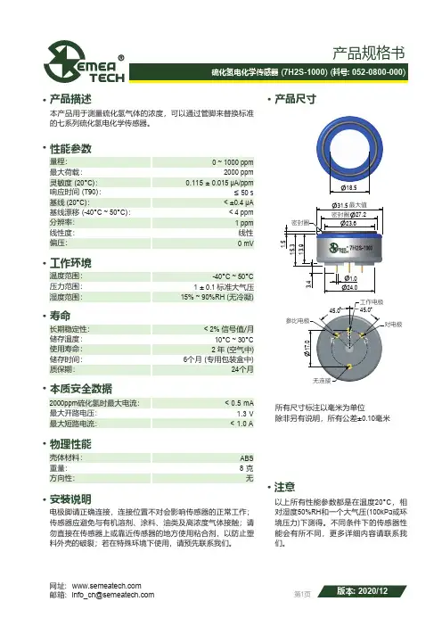
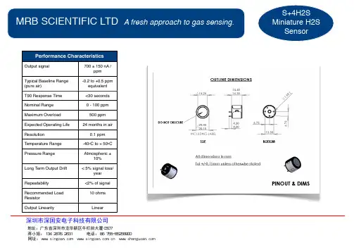
产品尺寸· 产品描述· 工作环境· 寿命· 本质安全数据· 物理性能· 安装说明·· 产品规格书最大荷载:灵敏度 (20°C ):响应时间 (T 90):基线 (20°C ):量程:温度范围:最大短路电流:最大开路电压: 2000ppm 硫化氢时最大电流:REV.: 2016-01性能参数·注意湿度范围:长期稳定性:储存温度:使用寿命:储存时间:24个月6个月 (专用包装盒中)ABS 分辨率:基线漂移 (-40°C ~ 50°C ):线性度:偏压:线性15% ~ 90%RH (无冷凝)2 年 (空气中)1 ± 0.1 标准大气压-40°C ~ 50°C 10°C ~ 30°C 以上所有性能参数都是在温度20°C ,相对湿度50%RH 和一个大气压(100kPa 或环境压力)下测得。
不同条件下的传感器性能会有所不同,更多详细内容请联系我们。
8 克无< 0.5 mA 1.3 V < 1.0 A网址: 邮箱: *********************重量:方向性:壳体材料: 第1页版本: 2020/120 mV< ±0.4 μA 0 ~ 1000 ppm ≤ 50 s< 4 ppm 2000 ppm 1 ppm0.115 ± 0.015 μA/ppm< 2% 信号值/月压力范围:质保期:电极脚请正确连接,连接位置不对会影响传感器的正常工作;传感器应避免与有机溶剂、涂料、油类及高浓度气体接触;请勿直接在传感器上或靠近传感器的地方使用粘合剂,以防止塑料外壳的破裂;若在特殊环境下使用,请预先联系我们。
本产品用于测量硫化氢气体的浓度,可以通过管脚来替换标准的七系列硫化氢电化学传感器。
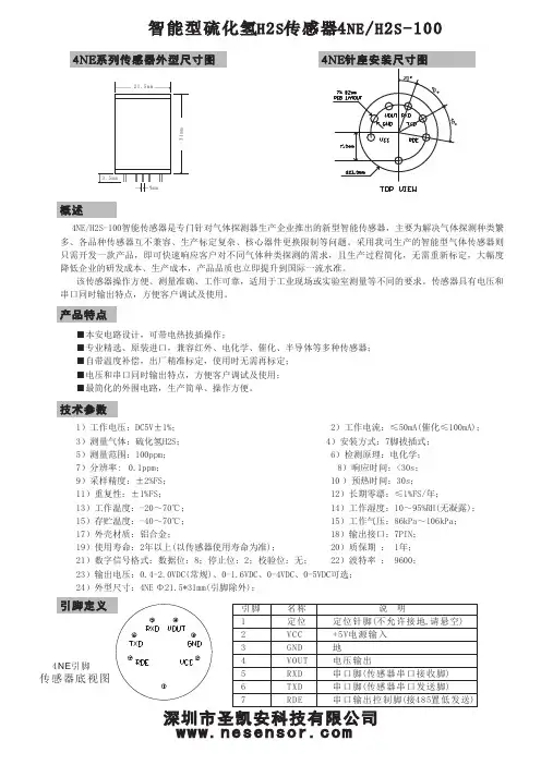
智能型硫化氢H 2S 传感器4NE /H 2S-1004NE /H 2S -100智能传感器是专门针对气体探测器生产企业推出的新型智能传感器,主要为解决气体探测种类繁多、各品种传感器互不兼容、生产标定复杂、核心器件更换限制等问题。
采用我司生产的智能型气体传感器则只需开发一款产品,即可快速响应客户对不同气体种类探测的需求,且生产过程简化,无需重新标定,大幅度降低企业的研发成本、生产成本,产品品质也立即提升到国际一流水准。
该传感器操作方便、测量准确、工作可靠,适用于工业现场或实验室测量等不同的要求。
传感器具有电压和串口同时输出特点,方便客户调试及使用。
■ 本安电路设计,可带电热拔插操作; ■ 专业精选、原装进口,兼容红外、电化学、催化、半导体等多种传感器; ■自带温度补偿,出厂精准标定,使用时无需再标定; ■ 电压和串口同时输出特点,方便客户调试及使用; ■ 最简化的外围电路,生产简单、操作方便。
1)工作电压:; ≤50mA (催化≤100mA );; 4 5ppm 6)检测原理:电化学;11)重复性; 12)长期零漂≤; 13)工作; 14)工作; 15)存贮; 15)工作;17)外壳材质; 18)输出接口 ; 19)使用寿命; 20)质保期 ; 21)数字信号格式; 22)波特率; 23)输出电压; 24)外型尺寸:4NE Φ21.5*31mm (引脚除外);DC5V ±1% 2)工作电流: 3)测量气体:硫化氢H 2S )安装方式:7脚拔插式;)测量范围:100; 7)分辨率: 0.1ppm ; 8)响应时间:<30s ; 9)采样精度:±2%FS ; 10 )预热时间:30s ; :±1%FS :1%FS /年 温度:-20~70℃湿度:10~95%RH(无凝露)温度:-40~70℃气压:86kPa ~106kPa :铝合金: 7PIN :2年以上(以传感器使用寿命为准): 1年:数据位:8;停止位:2;校验位:无: 9600:0.4-2.0VDC(常规)、0-1.6VDC 、0-4VDC 、0-5VDC可选31m m引脚名称说 明1234567定位VCC GND VOUT RXD TXD RDE 定位针脚(不允许接地,请悬空)+5V 电源输入地电压输出串口脚(传感器串口接收脚)串口脚(传感器串口发送脚)串口输出控制脚(接485置低发送)4NE 系列智能传感器数字通讯协议1、异步串行通信参数:始位: 1 数据位: 8 停止位: 2 校验: 无 波特率: 96002、帧格式:(每一通信帧的格式如下)H -数据头,为连续2 至4 个字节的FFH 。
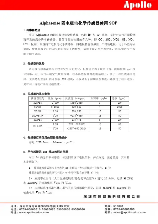
Alphasense四电极电化学传感器使用SOP1.传感器简述英国Alphasense的四电极电化学传感器,包括B4与A4系列,是针对大气环境检测而开发的高分辨率传感器,目前可稳定使用的有六种,即CO、SO2、NO2、O3、NO、H2S。
区别于常规的三电极电化学传感器,四电极传感器多出一个辅助电极,用于补偿零点电流,使其具有更好的响应时间和抗干扰特性,适用于固定及便携设备,城区/室内空气检测及烟气分析。
2.传感器的优势四电极传感器在结构上没有发生大的变化,但性能上有了质的飞越,能够做到ppb级分辨率,对于大气环境空气质量检测,在不降低检测精度的基础上,多了一种低成本的选择,尤其是配置原厂的开发板ISB模块,不仅降低了前期研发难度,还推进了项目进度,更有利于再现产品的优越性能。
3.传感器的基本参数传感器型号量程(ppm)灵敏度(nA/ppm)分辨率(ppb)过载(ppm)H2S-B40~1001450~20501200CO-B40~1000420~65042000NO-B40~20500~8501550NO2-B43F0~20-175~-4501550SO2-B40~100275~4755200OX-B4310~20-225~-550(O3)1550 0~20-250~-650(NO2)15504.传感器后期使用的硬件处理部分详见“ISB Rev4-Schematic.pdf”。
5.单传感器无ISB模块的标定问题对于B4高分辨率传感器,依然同常规三电极类似,两点标定,注意温度,其中基本步骤如下:1)传感器安装后初次上电老化24小时以上方可进行进一步操作;2)传感器安装放置在清洁空气中至少6小时(可包含在步骤1)中);3)应用零点空气(人工合成或纯净/净化的零点空气)通气20分钟,记录WE(OP1)和Aux(OP2)的输出电压V WE0和V AE0;4)应用低浓度标准气体,通气直止传感器输出稳定,记录WE(OP1)和Aux(OP2)的输出电压V WE和V AE;5)用工作电极和辅助电极的电压减去两个电极对应的零点输出电压,即V WE-V WE0和V AE-V AE0。
硫化氢H2S气体检测模块SKA/H2S-101NE Sensor硫化氢H2S气体检测模块产品概述SKA/H2S-101硫化氢气体检测模块是一款专门针对空气中存在的硫化氢H2S气体,进行24小时实时在线监测浓度含量的模块产品。
是圣凯安科技采用原装进口最优质的气体传感器,通过32位微处理器和24位数据采集器后,再多次进行全量程的温湿度补偿。
然后再用99.999%纯度的标准气体进行标定校准之后的产品模块。
可直接输出模拟电流4-20mA,模拟电压0.4-2V、0-5V,数字信号TTL,R S485通讯协议等信号。
因此,您购买后,无需二次开发,即可直接选用标准信号,进行数据传输、在线监测等工作。
SKA系列有毒有害、PID气体检测模块全部采用原装进口最优质的气体传感器,具体响应速度快、无零点漂移、一致性好等特点。
选用品牌包括英国CITY、德国SOLID、英国ALPHASENSE、瑞士MEMBRAPOR、英国DYNANENT、日本NEMOTO、美国BASELINE等产品优势●本案电路设计已经防止电路反接、电压过高、电流过大,同时产品设计考虑防雷。
●大屏幕液晶显示可24小时在线监测,实时显示气体浓度变化值。
●国外原装进口气体传感器,反应速度快、无零点漂移、低误差率、一致性好、抗干扰能力强。
●智能型软件处理:32位微处理器+24位采集芯片,可在00.000-99999数值之间任意值测量检测。
●多种量程单位可选:%LEL、%VOL、PPM、PPB、ug/m3;●多次实验检测全量程温湿度补偿和数据校准,大大提高了产品的精确度和稳定性。
●可检测500多种有毒有害气体,国内最全。
●信号输出:模拟电流4-20mA,模拟电压0.4-2V、0-5V,数字信号TTL,R S485通讯协议等信号;并可以选配1-2组继电器(开关量信号)信号输出,方便与风机或电磁阀的控制设备联动使用。
技术参数产品名称硫化氢H2S气体检测模块SKA/H2S-101检测气体硫化氢H2S检测原理电化学原理检测范围0-50ppm、0-100ppm、0-200ppm、0-500ppm、0-1000ppm、0-2000ppm、0-5000ppm等量程可选。
硫化氢传感器工作原理-回复硫化氢传感器是一种用于检测环境中硫化氢(H2S)浓度的传感器。
它广泛应用于煤矿、油田、化工厂等工业领域以及石油、天然气等能源行业中,用于监测硫化氢气体的浓度,以保障人员的安全。
硫化氢(H2S)是一种无色、有毒的气体,它具有强烈的刺激性气味,即使在低浓度下也会对人体造成眼睛、呼吸系统等方面的伤害。
因此,及早发现和监测硫化氢浓度的变化对于确保工作环境的安全至关重要。
硫化氢传感器通过测量环境中硫化氢的浓度,能够及时发出警告信号,以提醒人员采取必要的防护措施。
硫化氢传感器的工作原理基于电化学原理。
它通常由工作电极、对比电极和参比电极组成。
工作电极上涂有一种催化剂,常用的是银(Ag)或银/铂(Ag/Pt)合金,该催化剂能够促使硫化氢气体在电极表面发生氧化反应。
而对比电极与工作电极相互配对,用于测量工作电极上发生的氧化反应的电势变化。
当硫化氢气体接触到传感器表面时,它会在工作电极上发生氧化反应。
这个反应可以表达为以下方程式:H2S →2H+ + 2e-反应中生成的电子传递给对比电极,这导致对比电极上形成一个正电位的电压变化。
传感器会将这个电势变化转化为一个电信号,通常是电压或电流信号。
信号的大小与硫化氢气体浓度成正比。
为了保证传感器的准确性和稳定性,参比电极在传感器中起到重要的作用。
参比电极通常由银/银氯化银(Ag/AgCl)构成,它具有稳定的电位,并能够提供一个稳定的参考电势。
在实际应用中,硫化氢传感器一般需要与信号处理电路或控制系统结合使用。
信号处理电路负责将传感器输出的电信号进行放大、滤波和线性化处理,以便得到与硫化氢浓度准确对应的电信号输出。
控制系统则根据传感器输出的信号进行相应的报警或反馈控制,以便实时监测和调节硫化氢浓度。
除了电化学传感器,还有其他技术也可以用于测量硫化氢浓度,如半导体传感器和红外吸收传感器等。
这些传感器的工作原理有所不同,但都能够有效地检测硫化氢气体。
硫化氢传感器原理
硫化氢传感器基于化学反应原理进行测量。
它通常使用金属氧化物或半导体材料作为传感元件,并采用稳定电流源或恒压电源进行供电。
当硫化氢气体与传感器表面的材料接触时,会发生化学反应。
在金属氧化物传感器中,硫化氢气体可以与金属氧化物表面上的氧分子发生反应,生成硫酸盐,并引起电导率的变化。
而在半导体传感器中,硫化氢气体可与半导体材料表面的氧分子或其他化学物质发生反应,导致电阻值的变化。
该变化可以通过传感器中的电路进行测量。
传感器中的电路会将传感元件的电阻值或电导率转化为电信号输出,经过放大和处理后,传输给显示器或控制系统,以实时监测和报警。
为了提高传感器的灵敏度和选择性,可以采用不同的材料和结构设计。
例如,选择不同类型的金属氧化物或半导体材料,调整传感器的工作温度和气体浓度范围,以满足不同应用场景对硫化氢浓度的测量需求。
总之,硫化氢传感器利用化学反应原理,通过测量传感元件的电阻值或电导率的变化,实现对硫化氢气体的检测和测量。
这种传感器在工业领域和环境监测中广泛应用,能够及时发现潜在的硫化氢泄漏或污染问题,并采取相应的措施防止事故发生。
硫化氢传感器是一种用于检测和测量硫化氢气体的传感器。
它基于化学反应的原理,通过与硫化氢气体发生反应来产生电流或电压信号,从而实现对硫化氢浓度的检测和测量。
硫化氢传感器的工作原理可以分为以下几个步骤:
1.硫化氢吸附:当硫化氢气体接触到传感器表面时,它会与传感器表
面的吸附剂发生吸附作用。
吸附剂通常是一些具有高选择性和高亲和力的材料,如金属氧化物、聚合物或活性炭等。
2.化学反应:一旦硫化氢被吸附在传感器表面,它将与吸附剂发生化
学反应。
这个化学反应会导致传感器表面产生电荷转移或电子转
移,从而改变传感器的电学性质。
3.电流或电压信号输出:由于化学反应导致传感器表面电荷或电子的
变化,会产生一个电流或电压信号。
这个信号的大小与硫化氢的浓度成正比关系。
因此,通过测量这个信号的大小,就可以确定硫化氢的浓度。
4.信号处理和显示:传感器产生的电流或电压信号需要经过信号处理
电路进行处理和放大,然后通过显示器或数据接口输出给使用者。
这样,使用者就可以直观地了解硫化氢的浓度情况。
总之,硫化氢传感器的工作原理简单可靠,具有较高的灵敏度和选择性。
它可以广泛应用于环境监测、工业生产、医疗卫生等领域,用于检测和测量硫化氢气体的浓度。
然而,由于硫化氢气体的毒性较大,使用硫化氢传感器时需要注意安全操作,避免对人体和环境造成伤害。
ALPHASENSE USER MANUAL Page 14-20mA Transmitter for Toxic SensorsUMTOX-1 Issue 41INTRODUCTIONThe Transmitter PCB includes circuitry for a three electrode toxic sensor to convert the µA output signal from the sensor to a 2-wire 4-20mA signal. The transmitter board includes 4 mounting pillars that may be removed if not required.Alphasense 4-20 mA transmitters offer convenience and easy maintenance for toxic sensors:• Transmitters are shipped pre-calibrated for immediate use.• Circuitry includes onboard voltage regulator and uses low power two-wire transmitter systems, allowing the simplest possible wiring format.• Small circuit board size allows smaller sensor housing.• Conformally coated circuit board for environmental protection of circuit.• Low power circuitry with excellent performance means no degradation of sensor performance due to electronics.• Amplification of the sensor signal reduces noise pick-up and RFI/EMI susceptibility. Besides periodic sensor re-calibration, the transmitter electronics require no maintenance throughout the lifetime of the sensor. The sensor can be replaced at the end of the sensor working life. Re-calibration is required when the sensor is changed. See section 6.Please read these instructions to ensure correct installation, use and calibration of your gas sensor/ transmitter.2.1Transmitter SpecificationInput Voltage Required+7.5 to + 35 VDCOutput at zero gas concentration4mA (user adjustable)Output at full-scale20mA (user adjustable)Setability /stability<0.05mA (<0.25% FS)Maximum load @ 20 mA, 24 VDC825 ohms (see note)Supply voltage dependence< ±0.2 % output from +7.5 to +35 VDCConnector 2 pin Molex plug (ref. 22-27-2021)PCB current requirement<100 µAPCB dimensions39mm (dia.) x 19 mm (height)Operating conditions See sensor specificationCalibration (shipped pre-calibrated)multi-turn zero and span potentiometersPower supply protection Diode protection to voltage regulatorNo-power equivalent circuit Electrodes short- circuited via FETUMTOX-1Page 22.2Range/OptionsSensor and transmitter boards are shipped from Alphasense pre-calibrated. You may wish to confirm calibration. Standard available ranges are listed below:Sensor Ordering Code(includes sensor)Full-Scale Gas Concentration(ppm)Gain CO-BF THCO-BF 1000Low CO-BF TLCO-BF 100High H2S-BE THH2S-BE 1000Low H2S-B1THH2S-B1200Low H2S-B1TLH2S-B125High SO2-BF THSO2-BF 100Low SO2-BF TLSO2-BF 20High NO2-B1THNO2-B150High NO2-B1TLNO2-B110High CL2-B1TLCL2-B110HighTable 1Transmitter ordering codeAlthough the sensor and transmitter are pre-calibrated and the ranges are preset, it is possible to change range by adjusting the zero and gain potentiometers, which changes the circuit gain.Different sensors can be fitted to a transmitter board; if the gain is in the same category (low or high), then only re-calibration is necessary. If the sensor gain is different, then contact Alphasense for instructions on how to change range.Nitrogen dioxide and Chlorine (NO 2 and Cl 2) sensors give negative outputs, so Cl 2 and NO 2transmitters (THNO2-B1, TLCL2-B1 and TLNO2-B1) will not accept other sensors (CO,H 2S, SO 2), since they have an additional op amp stage to correct for this inverted output.See section 6.3Set Up3.1Mechanical MountingTransmitters are mounted to your housing using the four pillars pre-mounted to the PCB. Two sets of mounting holes are provided so that the sensor/PCB can be fixed to either the housing top (using the locating holes in the corner of the PCB) or to the base of the housing (using either set of locating holes). Figure 1 below shows mounting hole locations (dimensions are in mm). Figure 2 diagrams the sets of locating holes; normally the outerholes are used for mounting, while the inner e in the same location as the earlier issue of this PCB, allowing backward compatibility with the earlier PCB design.Figure 1. Outer mounting hole locations. Figure 2.Inner and outermounting holes.UMTOX-1 Page 3The pillars are tapped to accept an M3 pan head screw. We recommend a screw length that is at least 8mm to ensure rigid fixing. It is good practice to hold the pillar when screwing into the pillars to stop the pillar from rotating on the PCB. It may be easier to remove the sensor whilst screwing the circuit board pillars to your housing. If you move the pillars, ensure that if mounting to the lid of you housing that you include the washer between the pillar and PCB to ensure correct height of the pillar assembly. See figures 3 and 5.Figure 3. Mounting pillar configuration for .Figure 4. Mounting pillar configuration for attaching to the lid of an enclosure.attaching to the base of an enclosure.Figure 5. Side view of mounting to lid of an enclosure.Figure 6. Side view of mounting to the base of an enclosure.Allow 20 minutes after plugging the sensor back into the board for the output to stabilise.Ensure that the sensor is sealed securely to the top face of your housing. The O-ring supplied with your transmitter sensor should be used to ensure an airtight seal, avoiding any access of toxic or corrosive gases to the circuit board and the housing interior.fitted both sidesUMTOX-1 Page 43.2Connection and WiringPower to the transmitter board is via a Molex 2-pin mini plug (type 22-27-2021: supplied with the transmitter). Connect using a screened, two-core cable to the wires (black is ground, red is positive) by either soldering or using a screw terminal block. Twisted pairs can be used for shorter cable lengths. These leads can be shortened or extended as needed.3.3Power SupplyYour power supply must be between 7.5 and 35 VDC with less than 0.2V ripple.Do not supply mains AC power to this unit: this will destroy the transmitter and void the warranty.The transmitter is protected against incorrect polarity but will not function if you have reversed the power supply wires by connecting the Molex plug incorrectly to the transmitter board socket.When selecting the power supply voltage, you must not exceed the maximum total loop resistance, which includes your measuring resistor used to change the 4-20 mA current into a measured voltage.The transmitter requires a minimum of 7.5 volts to operate; therefore, the maximum potential drop allowed across your sensing resistor and cable is:(power supply voltage) -(7.5V)Assuming full-scale deflection at 20 mA, use Ohm's law to calculate the maximum loop (cable plus sensing resistor) resistance allowed.4Correct Usage and MaintenanceEnsure there is a good gas seal between the sensor and the housing; also if the sample is pumped, then ensure that the flow rate is sufficient. Alternatively, the sample gas can be allowed to diffuse to the front face of the sensor. The table below shows the recommended gas flow rate in standard cubic centimetres per minute (sccm). Higher flow rates may be used, but beware that pulsing flow and higher-pressure drops may lead to more erratic readings.Gas Flow Rate (sccm)CO300 to 500H2S400 to 700SO2400 to 700Cl2, NO2400 to 700Table 2Pumped gas recommended flow ratesThe only maintenance required is changing of the O-ring if it has been exposed to extreme environments for long periods (this O-ring should last the lifetime of the sensor in normal conditions). In addition, if the top dust/oil filter has become badly contaminated then contact Alphasense for replacement dust filter (section 5).UMTOX-1 Page 55Reordering Part NumbersReplacement sensor O-rings and dust/oil filters can be ordered by quoting the part numbers below.Part Number Description033-0002-00Replacement O-ring024-0011-00Self-adhesive dust/oil filterTable 3 Replacement Part Numbering6CalibrationThe 4-20mA transmitter is shipped pre-calibrated to the range shown in Table 1. Periodic re-calibration is required for all gas sensors, especially in safety-critical applications.To Calibrate:1First ensure that the power supply is connected correctly and a tight fitting flow hood is in place.2Ensure that a high quality zero gas source is available (e.g. cylinder of zero air or cleaned and scrubbed compressed air) and a bottle of calibration gas with validated accuracy (see Table 5 below).3Apply zero gas for 10 minutes at the flow rate shown in Table 2. Using a small screwdriver, adjust the zero potentiometer (RP2) until the reading is 4.00 ±0.05 mA.See figure 1, attached to this manual.4Apply test gas for ten minutes; the recommended test gas concentration for calibration is shown below in Table 4. Adjust the span potentiometer (RP1) with a small screwdriver until the reading is within ± 0.05 mA of the Span Calibration Point shown in Table 4 if you are using the recommended concentration.5Although it should not be necessary, it is good practice to recheck the zero after setting the span to ensure that the output is still 4.00 ± 0.05 mA in clean air ("zero gas"). Allow at least 10 minutes for full recovery to zero after the calibration gas has been removed.Transmitter Full-Scale(ppm)Calibration gas(ppm)Span Cal Point(mA)THCO-BF100040010.40TLCO-BF10010020.00THH2S-BE100040010.40THH2S-B120050 8.00TLH2S-B1252016.80THSO2-BF1005012.00TLSO2-BF201012.00THNO2-B1502512.00TLNO2-B110512.00TLCL2-B110512.00 Table 4 4-20 mA Transmitter Span CalibrationUMTOX-1 Page 67WarrantyTransmitters are warranted for two years. Sensors are warranted separately. If you have any difficulties or problems then contact:Customer SupportAlphasense LimitedOak Industrial ParkGreat DunmowEssex CM6 1XN, UKTel: +44 (0) 1371 878048Fax: + 44 (0) 1371 878066email:**********************8 AttachmentsFigure 7Circuit diagram@ Alphasense Limited 4 - 20mA Iss 4αlphasense Ltd3 Oak Industrial Park, Chelmsford Road, Great Dunmow, Essex, CM6 1XNTel:+44(0)1371 87 80 48 Fax: +44(0)1371 87 80 66 e-mail : ******************** web: 。