“固体火箭发动机气体动力学”课程 学习指南
- 格式:doc
- 大小:35.00 KB
- 文档页数:2
1.课程属性火箭武器专业(即武器系统与工程专业的火箭弹方向)的专业课程体系包括固体火箭发动机气体动力学、固体火箭发动机原理、火箭弹构造与作用、火箭弹设计理论和火箭实验技术。
“固体火箭发动机气体动力学”属于专业基础课,是该专业的先修课程。
2.为什么要学习固体火箭发动机气体动力学课程固体火箭发动机的工作过程是由推进剂燃烧和燃气流动构成的,燃气流动既是燃烧的直接结果,也是固体火箭发动机产生推进动力所需要的。
因此,燃气流动是“固体火箭发动机原理”的重要组成部分。
“固体火箭发动机原理”课程将固体火箭发动机内的流动处理成燃烧室内的零维流和喷管中的一维流,如果不学习本课程,一方面不易理解固体火箭发动机内的流动过程,对学好“固体火箭发动机原理”课程是不利的;另一方面,对毕业后继续深造的学生而言,缺乏必要的气体动力学知识,难以深入开展本学科领域的基础理论研究,而本科毕业后直接从事固体火箭研制工作的学生将难以利用先进的计算工具进行工程设计与性能分析,不能适应时代发展和技术进步的要求。
通过“固体火箭发动机气体动力学”课程的学习,学生既可以结合固体火箭发动机中的燃气流动问题,系统了解和掌握气体动力学的基本理论和计算方法,构建起完备的专业知识结构,同时也为学好后修课程奠定了坚实的理论基础,提高解决固体火箭发动机设计、内弹道计算、性能分析等实际工程技术问题的能力。
3.“固体火箭发动机气体动力学”的知识结构把握课程的知识结构是学好“固体火箭发动机气体动力学”的前提。
本课程由三个知识模块组成,即气体动力学基础知识、固体火箭发动机中一维定常流动和激波、膨胀波与燃烧波。
(1)气体动力学模块(14学时)该模块由教材的第一至第三章组成,是相对独立、自成系统的知识模块,目的是建立起基本的气体动力学系统知识,为学习第二个知识模块奠定必要的气体动力学理论基础。
该模块的主要知识点为♦课程背景♦流体与气体,气体的输运性质,连续介质假设,热力学基本概念与基础知识:系统,环境,边界,状态,过程,功,热量,焓,比热比,热力学第二定律,理想气体,等熵过程方程,气体动力学基本概念:控制体,拉格朗日方法,欧拉方法,迹线,流线,作用在流体上的外力,扰动♦拉格朗日方法与欧拉方法的关系,连续方程,动量方程,能量方程,熵方程♦流动定常假设,一维流动假设,一维定常流的控制方程组,伯努利方程,气流推力,声速,对数微分,马赫数,马赫锥,理想气体一维定常流的控制方程组,滞止状态,滞止过程,滞止参数,动压,气体可压缩性,临界状态,最大等熵膨胀状态,速度系数,气体动力学函数(2)固体火箭发动机中的一维定常流动模块(8学时)该模块为教材的第四章,是气体动力学知识在固体火箭发动机中的具体应用,分别针对喷管、长尾管、燃烧室装药通道展开讲述,最后简要介绍多驱动势广义一维流动。
课程名称:固体火箭推进基础及发展一、课程编码:0100029课内学时:48学分:3二、适用学科专业:航空宇航科学与技术,固体推进剂专业三、先修课程:高等数学,大学物理,航空宇航推进原理,固体火箭发动机设计,气体动力学基础,工程热力学,传热学等四、教学目标通过本课程的学习,掌握先进固体火箭推进的基本原理,并了解其它新型推进方式的概貌,提升学生对固体火箭发动机全方面的认识,为从事固体火箭发动机相关工作奠定基础。
五、教学方式教学方法以讲授为主,结合教学内容适当安排讨论课,内容以本阶段的讲授的内容和安排的课外阅读材料为主。
六、主要内容及学时分配A卷1.固体火箭发动机的燃烧与流动4学时1.1稳态燃烧1.2非稳态燃烧2.燃烧流场的现代诊断技术4学时2.1燃烧流场的速度诊断2.2燃烧流场的温度诊断2.3燃烧流场的密度组分和浓度诊断2.4凝相粒度及其尺寸分布诊断3.固体火箭发动机的结构与材料4学时3.1燃烧室壳体3.2推进剂装药结构完整性分析3.3喷管结构烧蚀3.4壳体尾管的绝热层和包覆层材料4.固体火箭发动机的喷焰特性4学时4.1火箭发动机喷焰的排气特征效应4.2排气特征的测量技术研究4.3排气特征的预估技术研究4.4减少排气特征效应的若干措施5.新型固体推进剂4学时5.1高能推进剂5.2高燃速推进剂5.3复合平台推进剂5.4固体推进剂的安全性5.5推进剂技术的发展趋势6.固体火箭发动机的现代设计与评估技术4学时6.1固体火箭发动机的现代设计技术6.2固体火箭发动机的现代评估技术6.3固体火箭发动机的故障分析6.4固体火箭发动机的参数辨识7.现代战术导弹发动机的发展和固体火箭发动机的应用前景4学时7.1战术导弹发动机的发展方向7.2当前研究的重点7.3固体短脉冲控制发动机8.冲压发动机8学时8.1冲压发动机的工作原理8.2整体式冲压发动机的主要组成部件8.3冲压发动机的发展B卷I Introduction2学时II Overall Design Approach2学时III Propellant Properties and Selection2学时IV Ballistic Analysis and Grain Design2学时V General Procedure for a Propellant Grain-Design Optimization and Computer-Aided Preliminary Design2学时VI Some Specific Cases2学时七、考核与成绩评定期末笔试:60%平时分组讨论考核:20%八、参考书及学生必读参考资料1.Jensen,G.E and Netzer D.W.Tactical Missile Propulsion[M].Reston:Progress inAstronautics and Aeronautics,Vol.170,19962.阿兰.达文纳斯.固体火箭推进剂技术[M].北京:宇航出版社,19973.张平等著,固体火箭发动机原理,北京理工大学出版社,19924.李宜敏,固体火箭发动机原理北京航空航天大学出版社,19915.(苏)阿列玛索夫等著,张大钦等译,火箭发动机原理,北京:宇航出版社,19936.王守范编著,固体火箭发动机燃烧与流动,北京工业学院出版社,1987.7.[美]萨顿G P,比布拉兹O著.火箭发动机基础.北京:科学出版社,2003.九、大纲撰写人:王宁飞。
固体火箭发动机原理第一章绪论1.1绪论火箭发动机:自身携带燃料和氧化剂的喷气发动机(推进剂燃烧不需要依靠空气中的氧气)吸气发动机:自身只携带燃料,燃烧所需要的氧化剂需要吸收空气中的氧气,吸气发动机只能在大气层中工作。
固体火箭发动机(solid propellant rocket engine):使用固体推进剂,燃料和氧化剂预先均匀混合液体火箭发动机(liquid propellant rocket engine):使用液体推进剂(由液态燃料和液态氧化剂组成),常见的有单组元推进剂——肼,以及双组元推进剂——液氢和液氧1.2 固体火箭发动机的基本结构和特点固体火箭发动机的基本结构:固体推进剂装药、燃烧室、喷管、点火装置。
固体火箭发动机的类型:固体、液体、固液混合火箭发动机固体推进剂(是固体火箭发动机的能源和工质)种类:双基、复合、复合改双基推进剂装药方式:自由装填(通常需要挡药板使药柱固定)、贴壁浇注包覆层:用阻燃材料对装药的某些部位进行包覆,以控制燃烧面积变化规律燃烧室(是固体火箭发动机的主体,装药燃烧的工作室)特点:有一定的容积,且对高温高压气体具有承载能力材料:合金钢、铝合金、或玻璃纤维缠绕加树脂成型的玻璃钢结构形状:长圆筒型热防护法:在壳体内表面粘贴绝热层或采用喷涂法喷管(是火箭发动机的能量转换部件)拉瓦尔喷管:由收敛段、喉部、扩张段组成中小型火箭多采用锥形拉瓦尔喷管(收敛段和扩张段均为锥形)大型火箭一般使用特型拉瓦尔喷管(扩张段为双圆弧、抛物线等)喷管基本功能:1.通过控制喷管喉部面积大小以控制排出的燃气质量流率,以控制燃烧室内燃气压强2.利用先收敛后扩张的喷管结构使燃气由亚声速加速到超声速喉部材料:(喷喉处工作环境恶劣,常发生烧蚀或沉积现象),需采用耐高温耐冲刷的材料,石墨、钨渗铜等点火装置(提供足够的热量和建立一定的点火压强,使装药的全部燃烧表面瞬时点燃,尽早进入稳态燃烧)组成:电发火管+点火剂(烟火剂或黑火药)或点火发动机(尺寸较大的装药)固体火箭发动机的特点:优点:1.结构简单(固体火箭发动机最主要的优点)。

上篇热工基础概述一、课程的性质任务1、什么是热工过程,什么是热工设备?热的来源、传递、利用过程;产生热量、利用热量的设备;包含的内容有:研究系统的工作介质、体系的性质以及做功等2、该门课的性质:专业基础与技术课课程的任务:是将热力学的基本原理知识、流体力学的基本知识与工程实际上的热工设备相结合,研究热工过程中的各参数变化情况。
也就是说将讨论与热工过程有关的气体流动性质、气体性质、热的产生,传递、交换及过程中的物质交换等。
3、研究内容二、课程特点:强调“三传一反的能量交换”:动量、质量、热量传递、燃烧与烧成反应。
强调平衡概念:物料平衡、动量平衡、能平衡,强调基本:基本概念、基本定律、基本方法、基本理论知识强调理论与实践用基本的理论知识去理解硅酸盐行业常见的热工设备的工作原理。
强调分析问题、解决问题的能力。
三、课程的主要研究方法1.数学方法:微分方程和积分方程的求解及数值求解;2.分析方法:过程分析与数量级分析等;3.模型方法:物理模型及数学模型的建立;4.类比方法:热电类比及动量,质量,热量传递的类比等。
四、学习本课程的目的与意义1、掌握本专业中所用的热工理论知识,用所学的知识解决工程中出现的问题。
2、在该基础上进一步的深入研究创新,开发新型的热工设备五、本课程的基本要求1、注重研究的方法和思路:要掌握基本概念、掌握基本理论的来龙去脉,强调概念明确、思路清晰。
2、注重理论应用,多做习题,熟悉基本概念与理论。
3、答疑、作业、课堂讨论、考试。
六、课时安排(76学时)绪论(1学时)第一章气体力学在窑炉中的应用(10学时)第二章传热原理(22学时)第三章质量原理(2学时,自学)第四章燃料及其燃烧过程与设备(12学时)第五章干燥过程及设备(10学时)第六章物料烧成与窑炉(18学时)小结(1学时)实验(?学时)七、教材及教学参考书教材:孙晋涛编《硅酸盐热工基础》武汉工业大学出版社参考书(1)沈慧贤胡道和主编《硅酸盐热工工程》武汉工业大学出版社(2)蔡悦民编《硅酸盐工业热工技术》武汉工业大学出版社(3)姜金宁编《热工过程与设备》冶金工业出版社(4)杨世铭编《传热学》人民教育出版社(5)韩昭论主编《燃料及燃烧》冶金工业出版社(6)胡道和编《水泥工业热工设备》武汉工业大学出版社(7)刘振群《陶瓷工业热工设备》武汉工业大学出版社(8)孙曾绪《玻璃工业热工设备》武汉工业大学出版社第一章气体力学在窑炉中的应用内容:研究气体流动规律及相应的热工流动设备。
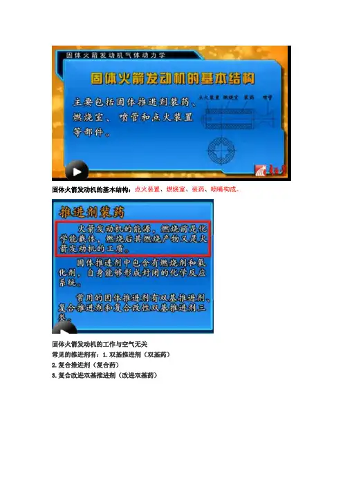
固体火箭发动机的基本结构:点火装置、燃烧室、装药、喷嘴构成。
固体火箭发动机的工作与空气无关常见的推进剂有:1.双基推进剂(双基药)2.复合推进剂(复合药)3.复合改进双基推进剂(改进双基药)直接装填!形式:自由装填:药柱直接放在燃料室贴壁浇筑:把燃料直接和燃烧室粘贴在一起(液体发动机发射前现场加注推进剂)固体火箭一旦制造完成即处于待发状态经过压身或浇注后形成的一定结构形式的装药我们叫他装药或者药柱药柱的燃烧面积在燃烧过程中随时间变化必须满足一定的规律完成特定任务所需要的。
装药面积的燃烧规律决定了发动机压强和推力面积的发展规律。
为了满足上述规律需要对装药的表面用阻燃层进行包裹,来控制燃烧面积变化规律。
药柱可以是:当根、多根,也可事实圆孔药,心孔药燃烧室是一个高压容器!装药燃烧的工作室。
燃烧时要求要求:容积、对高温(2000-3000K)高压气体(十几到几十兆帕)的承载能力与高温燃气直接接触的壳体表面需要采用适当的隔热措施高温高压燃气的出口作用:1.控制燃气流出量保持燃烧室内足够压强。
2.使燃气加速膨胀,形成超声速气流,产生推动火箭前进的反作用推力。
部件作用:进行能量转化工艺特点:形状:先收拢后扩张的拉瓦尔喷灌,由收敛段、头部、扩张段、中小型火箭,锥形喷管(节省成本和时间)工作时间长、推力大、质量流速大采用高速推进剂的大型火箭采用特制喷管(收敛段和和直线段的母线可能不是直线可能是抛物线双圆弧)仔细设计型面,提高效率作用:使燃气的流动能够从亚声速加速到超声速流喉部环境十分恶略,烧蚀沉积现象影响性能(改变喉部尺寸改变性能)。
其他内表面采用其他相应的防护措施。
短时间不用采用喉衬!点火装置!!电发火管+点火药装在盒子里大型发动机(直径比较粗长度比较长)用小发动机点燃,点火发动机可靠性最低的部件要求:战术火箭(-40度-55度都能点燃)点火药量选择很重要充气后再打开喷嘴能量转化过程1:推进剂部分化学能-燃烧产物热能能量转化过程2. 燃烧产物热能-射流的动能(喷管完成)能量转化过程3. 射流动能-(直接反作用力)-飞行器动能固体燃料发动机本质是:能量转换装置!固体火箭发动机的工作过程是复杂的,装药燃烧与燃气流动的复杂过程相互作用的过程!!燃烧与流动是固体火箭发动机所要解决的基本问题那些流动现象及其作用:燃烧产物的流动是燃烧的直接结果没有流动会造成发动机爆炸!!!适当的流动状态是燃烧得以稳定燃烧的条件。
02 航天学院序号:课程编号:02M001课程名称:线性系统理论任课教师:周军刘莹莹英文译名:Linear System Theory先修要求:《线性代数》和《矩阵论》中任一门、《复变函数》内容简介:《线性系统理论》是控制类、系统工程类、电类、计算机类、机电类等许多学科专业硕士研究生的一门公共基础理论课,是控制、信息、系统方面系列理论课程的先行课。
《线性系统理论》是最优估计、最优控制、系统辨识、自适应控制等现代控制理论的基础,系统讲述线性系统的运动规律,揭示系统中固有的结构特性,建立系统的结构、参数与性能之间的定性和定量关系,以及为改善系统性能,满足工程指标要求而采取的各类控制器设计方法。
具体的内容包括:线性系统的状态空间描述、状态空间描述与传递函数描述的关系、线性系统的运动分析、能控性、能观性、稳定性理论、线性反馈系统的状态空间综合方法、线性鲁棒性控制基本理论、线性系统的基本代数理论,以及多变量频域设计方法等。
主要参考书:(1)《线性系统理论》阙志宏主编,西安西北工业大学出版社,1995;(2)《现代控制理论引论》周凤歧等,北京国防工业大学出版社,1988;(3)《线性理论》郑大中编著,北京清华大学出版社;(4)《线性系统理论与设计》[美]陈启宗,科学出版社,1988。
序号:课程编号:02M900课程名称:专业英语任课教师:周军英文译名:Professional English先修要求:专业方面的课程内容简介:本课程作为一种基本的专业英语技能,在阅读和学习与本专业的相关的国外文献资料时,发挥着重要的作用。
因此,主要学习和掌握专业外语的基本语法、句法和结构,通过这门课的学习,期望学生能掌握专业英语的特点;扩大专业英语词汇量,尤其关于本专业有关导弹、航天器、无人机等专业知识方面的英语词汇量;提高专业英语(或科技英语)文章的阅读速度;并进行相应专业英语文献的翻译,在此基础上掌握专业英语的写法,为今后从事工程技术和科学研究工作打下稳固的基础。
vESRA 30K Team: SolidPropellant Rocket Motor2019-2020An Informative Presentation●Michael Barden ●Cole Domenico ●Tom Gerendsay ●Caspar Hendrickson ●Jon Campillo ●Carter Hazen ●Harjot Saran ●Mat Van Gordon1.Primary Components2.Propellant formulation3.Characterization4.Burnsim5.DAQ6.Motor Tube Design7.CPV8.Thermal Liner9.Forward Enclosure10.Nozzle11.Testing12.Project schedule13.Key Takeaways &RecommendationsESRA Propulsion TopicsPrimary ComponentsForward Enclosure: Caps off forward end and prevent gas from getting behind thermal linerThermal Liner: Fiberglass Tube, Prevents the heat of the fuel from reaching motor tubeFuel Grains: Solid Propellant that burns on interior face ate pressures (`700 psi)Casting Tubes: Cardboard tubes that the propellant is packed into to shape itMotor Tube: Aluminum tube that holds pressure of firingNozzle: Graphite nozzle that converts high pressure into supersonic flowPropellant FormulationA new chemical formulation named Liquid Schwartz (LS) was given by OROC mentor Jim Baker. Jim Baker is an experienced chemist in the aerospace industry and a mentor of OSU’s solid rocket motor propulsion sub-teams. The new chemical formulation was based on previous year’s composition, Orange Koolaid. The goal was to reduce the complexity of the chemical composition and to reduce total mixing time. The LS formulation consists of six primary ingredients, each with different mass fractions.Propellant Formulation ●Why use Propep?○Propep is a propellant evaluation program used todetermine the chemical composition for the combustion of asolid rocket propellant. After inputting chemical makeup andoperating conditions, Propep provides theoreticalperformance parameters of the propellant composition.●Liquid Schwartz (LS) Propep Output○The photo represents the chemical makeup of LS and it’s performance parameters.The parameters calculated inPropep are transferred to a separate simulation softwarecalled Burnsim.●Mixing Process○The mixing process consists of combining all the ingredients and casting into individual propellant grains.○Click this link to see casting tubes.○Click this link to see an example of a propellant mix.○Click this link to see the LS Batch Sheet.○Click this link to see Mixing SOP.Characterization●Characterization: The process of determining the burncharacteristics of solid rocket propellant using data gathered fromsub-scale motor testing. (Relate P to R)●Why Characterize?○Characterization can be used to predict the performance offull-scale motors○Knowing what to expect allows us to build SAFE rockets●What does successful characterization look like?○Solve for the coefficients of Muraour’s Linear Burning RateLaw (A & n)Muraour’s Linear Burning Rate Law:R=AP nR = Propellant burn rateP = Motor chamber pressureA = Constant of proportionalityCharacterization - The Process●Characterization Inputs:○Geometry of propellant grains○Geometry of nozzle○Pressure curve from subscale testing○Density & mass of propellantNozzle Propellant GrainCharacterization - The Process●Next steps:○Determine range of steady-state (SS) burning○Get SS burn time○Calculating A & n requires burn rate. There are two differentmethods of determining burn rate:■Calculate instantaneous burn rates for each pressure datapoint (Richard Nakka’s method)■Calculate average burn rate for entire test (Jim Baker’smethod)○Plot burn rate vs. chamber pressure. Then fit a line of best fitcurve of the form: R = A*P^n to solve for A and n.Characterization - Possible Improvements●Increase the uniformity of propellant batches○Employ vacuum casting○Keep ingredient sources constant○Keep mixing environment constant●Characterize propellant at three different temperatures○Currently, characterization is only valid for ~40-50°F○Temperature affects burn rateBurnSim●Why use BurnSim?○Simulation program used to predict the performance characteristics of a solidpropellant rocket motor.○Aids in calculating theoretical nozzlegeometry.●Burnsim Program Inputs○Propellant characteristics■ A and N values■Propellant density■Characteristic velocity○Grain Geometry■Grain Length■Grain Diameter■Grain Core Diameter○Nozzle Geometry■Nozzle throat diameter■Nozzle exit diameter■Nozzle efficiency■Ambient pressureDAQ●DAQ 3.0○Pressure, thrust, and thermal data is collected with the data acquisition system.○Manual can be found here: DAQ 3.0 Manual●What sensors do we have?○Futek PFP350 (0-3000psi) pressure transducer○OMEGA LCM 305 (0-10,000N) load cell○OMEGA XCIB-K-4-5-10 Thermocouples (x6)○Read the DAQ 3.0 manual to learn how tooperate it. The DAQ works with mV/V sensorsand Type K thermocouples.●Next Prototype○DAQ 4.0 was created spring of 2020.■Compatible with various sensor outputtypes:●mV/V●0-5V or 0-3.3V●4-20mA■Compatible with (K, J, N, R, S, T, E, andB) thermocouples.■Improved precision.DAQ - Testing setup●Pressure transducer is connected to forwardenclosure by copper tubing for ease ofconnection, and to protect the sensor fromheat.●Motor sits on top of load cell to gather thrustdata to predict altitude.●Subscale thrust data is used as a double checkwhen calculating burn rate.DAQ - Calibration ●FUTEK pressure transducercalibration was supplied byFUTEK. The calibration isapplied in the DAQ 3.0 code,so pressure channel is reportedin PSIA.●Load cell was calibrated usingthe INSTRON.DAQ - Calibration ●Thermocouples don’trequire calibration. K typeoutput can be correlatedto temperature fromlookup table: LookupTable●Accuracy can be slightlyincreased by individuallycalibrating each probe.●DAQ outputs thecalibrated temperature.No need to use any ofthis.Motor Tube●What is a motor tube?○The motor tube is the component that gives structure to the overall motor assembly and is the main component in containing the pressure during operation.●Dimensions○60” length○6” outer diameter○ 5.5” inner diameter○0.25” thick on ends○0.175” thick in the middle●Safety Factor○Calculated to approx. 4.1 during operational pressures of 600 psi.●Material Selection○Aluminum 6061-T6, selected over aluminum 7071 due to its availability, cost, and manufacturability●Machining○Currently, OSU does not have the capabilities to accommodate a 60” tube on any of their lathes or CNC machines○Utilized P&J Machining to have the motor tubes manufactured out-of-house■https:///Motor Tube - Design Changes●Length○Increased to 60” from the previous years 48” to allow for the greatest volume of propellant●External shoulder○Created curved shoulders instead of a sharp step down to the smaller diameter to reduce stress concentrations●Extended length of full thickness sections at ends○The temperature is highest at the shoulder where the nozzle presses up against the thermal liner, so the motor tube’s thickest points wereextended over this weak point●Snap rings instead of radial bolts○Reduces manufacturing effort on both the motor tube and forward enclosure○Integration time is reduced drasticallyPrevious YearsDesign Current DesignMotor Tube - Possible Improvements●Length○With a better formulation for the propellant, the motor tube’s length can most likely be reduced now that there is reliable data to more accurately simulate the required volume of propellant.●Thickness of material at forward enclosure end○The temperatures recorded at the forward enclosure are not extreme enough to make the thicker sections as necessary. This means that more of the tube can be a thinner diameter to save on weight.●Material○If a reliable aluminum 7071 supplier is found, it is a much better material in terms of its properties. A long time was spent attempting to source any, but all the options that were found were extremely expensivewith a very low amount of material in stock. So, while it has the capability of being a drastic improvement,unless a source is found that has a large inventory with decent prices, stick to aluminum 6061.○If possible, continue the deal with P&J Machining to acquire material and machine through them. Online Metals is an option that previous teams have used to purchase motor tube stock, but there are morefrequent issues with defects in their product that is hard to identify without the proper tools. So, it is helpful to have professionals who verify the stock first and know what to watch out for.●Boat Tail Integration○Incorporate design features in the motor tube to secure the boat tail of the rocket sooner. The motor tube was adapted later on in the project to make this attachment point possible, but it would have madeintegration into the rest of the rocket smoother if there had been attachment points in the design from thebeginning.●Why Use a Thermal Liner?○ A layer of insulating material will allow for a reduction of the rateat which heat may be diffused into the casing walls. The idea is to use a material that won’t completely burn away after a single usage.●Material Selection ○We used fiberglass thermal liners to protect the Aluminum6061-T6 from the propellant. ○Fiberglass was durable and amazing with how well it handled themassive temperature change. Transfers almost no heat to the aluminum.●Our Advice ○Fiberglass is heavy! A large portion of the motor’s weight is theliner. We cautiously recommend looking into experimentation with thermal liner. ○If there is no need for change in material, look for a reduction ofthe thickness so you don’t have to spend time sanding down the fiberglass. Or look into possibly laying up your own fiberglass liner.●Link for Thermal Liner We Used ○https:///product-category/exhaust-tubing/Thermal LinerForward Enclosure●Snap Ring ○Prevents FE from moving axially ●Pressure Transducer ○¼ in NPT threaded hole for pressure transducer ●Eye Bolt Holes ○Holes to connects parachute eye bolts and rest orocket●Thermal Liner O-Rings ○Primary O-ring set prevent hot gasses fromcirculating behind the thermal liner●Casing O-Rings ○Secondary set of O-rings to provide fail-safe toDesign Features:●Why Use a Forward Enclosure?○The forward enclosure caps off forward end of therocket using multiple sets of O-rings to prevent the combustion gasses from circulating behind the thermal liner or escaping the end of the motor.●Material Selection ○6061-T6 was chose due to its availability and pricepoint as material strength is not a concern for this part.●Our Advice ○This design works well but could be optimized forweight and additional sensors could be added.○The machining process takes a long time if this canbe done on a CNC lathe you will save your self days.Nozzle●Why use a Nozzle?○The purpose of a isomolded graphite de laval nozzle is to channel and accelerate the flow of combustion gasses to asupersonic velocity.●Importance?○The nozzle design dictates:■The thrust produced by the rocket motor.■The internal chamber pressure experienced by therocket motor.■The rate at which the propellant will burn.●The Goal?○The goal of the nozzle is to maximize the velocity of the exhaust gasses without over-pressurizing the aluminum6061 motor casing.●Material Selection○Isomolded graphite is used to manufacture the nozzle.■Graphite is easy to manufacture using the OSUSummit lathe.■Graphite is a structurally reliable material in highheat applications.■Graphite is affordable.○Graphite is ordered from the Graphite store. Click here.Nozzle●Avoiding Inefficiencies○There are two expansion behaviors that induce inefficiencies in nozzle performance: Over-expanded flow and under-expanded flow.■Over-expanded Flow: Occurs when the ambient pressure is higher than the nozzle exit pressure. This type of expansion behavior results in constricted flow of combustive gasses. Over-expansion can bemitigated by shortening the length of the nozzle or decreasing the diverging angle to decrease the nozzleexit area to a point where the nozzle exit pressure is equal to the ambient.■Under-expanded Flow: Under-expanded flow occurs when the ambient pressure is less than the nozzle exit pressure. This type of expansion behavior results in an expanded flow of combustive gasses.Under-expansion can be mitigated by increasing the length of the nozzle or increasing the diverging angleto a point where the nozzle exit pressure is equal to the ambient.1.SUB-SCALE Essentially a miniature version of the motor used for collecting data about the propellant. Multiple subscale tests are used to characterize the propellant and discover the A and n values.2.HYDROSTATICUsing the full scale motor, water is pumped in until the motor is full and is then sealed by a second forward enclosure. A grease gun is then used to pressurise to 1.5x the operational pressure and held there for several minutes. This ensures that the motor is unlikely to fail during a full-scale test fire. See link for procedure here .3.INTEGRATIONCompletely assemble the full-scale motor. This is a dry run to make sure all components integrate correctly and the motor is ready for full-scale static testing. See link for procedure here .4.FULL-SCALEThe full-scale motor is statically test fired to gather thrust, pressure, and temperature data. Data is collected into test report. See example here .Testing●Fall Term:○Chemical formulation ■Design the formula■Mix sub-scale batch■Design and build sub-scale test stand■Design and build sub-scale ignition system■Gather data from subscale static fire ■Characterized formula from static fire data. (We repeated these steps a few times before we were satisfied with the data).○Design full-scale motor assembly ■Forward enclosure■Motor tube■Nozzle■Thermal liner ■Casting tubes●Winter Term:○Validate motor design ■Full-scale static test fire■Mix full-scale motor■Finish manufacturing motor assembly■Design and build full-scale test stand■Design and build full-scale ignition system■Gather data from full-scale static test fire ■Repeat if necessary. (We repeated to get a faster ignition.)Project Schedule●Winter Term - Continued:○Prepare for test flight ■Build full-scale motor■Design and build igniter for rocket on the rail ■Design and build a system to log pressure data while in flight■Conduct test integration of motor into rocket●Spring Term:○Build additional motors for further testing and competition○Support other sub-teams○Document work ○Develop equipment for future ESRA yearsProject ScheduleKey Takeaways & Recommendations●Follow safety procedures at all times.●Measure twice, cut once.○Always reference CAD modeling when manufacturing andintegrating components.●Make sure to research completely and make informed, justified decisions.○Recommend reading Solid Rocket Propellant Technology●Seek low-risk design changes to reduce weight of rocket motor.○Phenolic Nozzle○Vacuum Casting Grains○Reduce thickness of fiberglass liner●Aim to complete subscale testing by the end of fall term.●Always seek help and ask questions. Our mentors are outstanding!Thank You!v。
1.课程属性
火箭武器专业(即武器系统与工程专业的火箭弹方向)的专业课程体系包括固体火箭发动机气体动力学、固体火箭发动机原理、火箭弹构造与作用、火箭弹设计理论和火箭实验技术。
“固体火箭发动机气体动力学”属于专业基础课,是该专业的先修课程。
2.为什么要学习固体火箭发动机气体动力学课程
固体火箭发动机的工作过程是由推进剂燃烧和燃气流动构成的,燃气流动既是燃烧的直接结果,也是固体火箭发动机产生推进动力所需要的。
因此,燃气流动是“固体火箭发动机原理”的重要组成部分。
“固体火箭发动机原理”课程将固体火箭发动机内的流动处理成燃烧室内的零维流和喷管中的一维流,如果不学习本课程,一方面不易理解固体火箭发动机内的流动过程,对学好“固体火箭发动机原理”课程是不利的;另一方面,对毕业后继续深造的学生而言,缺乏必要的气体动力学知识,难以深入开展本学科领域的基础理论研究,而本科毕业后直接从事固体火箭研制工作的学生将难以利用先进的计算工具进行工程设计与性能分析,不能适应时代发展和技术进步的要求。
通过“固体火箭发动机气体动力学”课程的学习,学生既可以结合固体火箭发动机中的燃气流动问题,系统了解和掌握气体动力学的基本理论和计算方法,构建起完备的专业知识结构,同时也为学好后修课程奠定了坚实的理论基础,提高解决固体火箭发动机设计、内弹道计算、性能分析等实际工程技术问题的能力。
3.“固体火箭发动机气体动力学”的知识结构
把握课程的知识结构是学好“固体火箭发动机气体动力学”的前提。
本课程由三个知识模块组成,即气体动力学基础知识、固体火箭发动机中一维定常流动和激波、膨胀波与燃烧波。
(1)气体动力学模块(14学时)
该模块由教材的第一至第三章组成,是相对独立、自成系统的知识模块,目的是建立起基本的气体动力学系统知识,为学习第二个知识模块奠定必要的气体动力学理论基础。
该模块的主要知识点为
♦课程背景
♦流体与气体,气体的输运性质,连续介质假设,热力学基本概念与基础知识:系统,环境,边界,状态,过程,功,热量,焓,比热
比,热力学第二定律,理想气体,等熵过程方程,气体动力学基本
概念:控制体,拉格朗日方法,欧拉方法,迹线,流线,作用在流
体上的外力,扰动
♦拉格朗日方法与欧拉方法的关系,连续方程,动量方程,能量方程,熵方程
♦流动定常假设,一维流动假设,一维定常流的控制方程组,伯努利方程,气流推力,声速,对数微分,马赫数,马赫锥,理想气体一
维定常流的控制方程组,滞止状态,滞止过程,滞止参数,动压,
气体可压缩性,临界状态,最大等熵膨胀状态,速度系数,气体动
力学函数
(2)固体火箭发动机中的一维定常流动模块(8学时)
该模块为教材的第四章,是气体动力学知识在固体火箭发动机中的具体应用,分别针对喷管、长尾管、燃烧室装药通道展开讲述,最后简要介绍多驱动势广义一维流动。
本知识模块的目的是为学生学习固体火箭发动机原理奠定理论基
础。
该模块的主要知识点为:驱动势,简单流动,变截面一维定常等熵流动,膨胀加速流,压缩减速流,流动壅塞,收敛管道极限状态,几何条件,最佳膨胀欠膨胀状态,过膨胀状态,喷管扩张比,排气速度,真空推力,最佳推力,推力系数,喷管理论性能参数,简单摩擦管流,摩擦壅塞,等截面摩擦管最大管长,固体火箭发动机长尾管,简单换热管流,热阻,加热壅塞,临界加热量,加热管流最大进口马赫数,简单加质流动,垂直于主流的质量添加,加质壅塞,临界质量流率,广义一维定常流动,综合驱动势,多驱动势定常流动特点,驱动势的抵消(3)激波、膨胀波与燃烧波模块(8学时)
该模块为教材的第五章,具体应用于固体火箭发动机的喷管和燃烧室装药通道,并奠定学习外流和火箭外弹道课程的理论基础。
同时,该模块作为扩展的气体动力学知识,可以引导学生了解固体火箭发动机的燃烧理论和冲压发动机进气道原理。
该模块的主要知识点为:激波性质,激波的产生,激波的传播速度,激波类型,激波研究方法,膨胀波,燃烧波,正激波,激波解,激波强度,朗金-雨贡纽方程,弱正激波,伪等熵压缩,普朗特速度方程,激波阻力,拉瓦尔喷管第一临界反压,拉瓦尔喷管第二临界反压,拉瓦尔喷管第一临界反压,力学条件,流动偏转角,斜激波波角,最大流动偏转角,激波脱体,激波规则反射、马赫反射,滑移线,激波消除,异侧激波规则相交、马赫相交,普朗特-迈耶流,扇形膨胀区,普朗特-迈耶角,普朗特-迈耶角最大值,爆燃波,爆震波,雨贡纽曲线,瑞利曲线,查普曼-儒盖点,ZND爆震波模型。
4.怎样学好固体火箭发动机气体动力学
(1)气体动力学模块
气体动力学与工程热力学是密切相关的,如热量、功、熵,焓、过程、状态等概念贯穿整个知识模块,因此,在学习本模块之前,建议学生简单复习一下工程热力学的基本内容。
本知识模块的核心内容是教材的第三章,而第三章的核心是一维定常流的控制方程组和三个特殊状态(滞止状态,临界状态,最大等熵膨胀状态),是本知识模块必须掌握的内容。
(2)固体火箭发动机中的一维定常流动模块
一维定常管流是固体火箭发动机中真实内流场的合理简化,本模块主要包括变截面一维定常等熵流动、有摩擦一维定常绝热流动、具有传热的一维定常流动和有质量加入的一维定常流动,分别对应于固体火箭发动机不同部件的流动过程。
本模块得核心内容主要是流动壅塞概念和拉瓦尔喷管的力学条件,也是模块的难点。
为了掌握并深刻领会本模块的知识点,课程中使用了大量的算例、计算机软件、动画演示等教学手段,通过总结流动的共性规律,使学生学会举一反三。
建议在学习本模块之前,全面复习气体动力学模块,特别是关于临界状态的概念。
(3)激波、膨胀波与燃烧波模块
本模块的主要难点是拉瓦尔喷管中产生正激波的几个临界条件和激波脱体概念。
拉瓦尔喷管中的正激波与第四章一维定常变截面流动相联系,要理解拉瓦尔喷管仅是亚声速流动变成超声速流动的几何条件,而且是必要条件,喷管能否真正获得超声速流还需要看下游环境条件是否允许。
建议学生掌握讨论的前提条件,并深刻领会第三章给出的面积比函数的意义。
激波脱体条件是由波前马赫数和流动偏转角共同决定的,建议学生想象教材中的图5-12和图5-13是如何绘出的,并尝试使用任何一种计算机语言编写计算程序,以领会波前马赫数、波角和流动偏转角的关系。