milog3电子压力记录仪使用说明书
- 格式:doc
- 大小:24.80 MB
- 文档页数:26

The OMEGA OM-DLAC Data Logger is a self-contained precision instrument for recording AC Current using a clamp on probe. The OM-DLAC can store up to 16,000 measurements for each recording. The recordings can be read using the supplied PC interface or the optional OM-DP3 Data Plotter.The Windows™ compatible software allows the user to set the OM-DLAC for a recording session, read the recorded data in text or graphical format, and to store the recorded data for future reference or analysis. Applications include monitoring of compressor and fan run cycles, new installation tests, trouble shooting intermittent problems, etc. Refer to the following instructions for expla-nations of how to record and how to retrieve AC Current recordings.S OFTWARE I NSTALLATIONThe Data Logger to PC program is supplied on 3-½″ floppy disks. To install the software follow the instructions below:1.Insert disk 1 of 2 into Drive A.1.If you are using Window™98/95, click on START, then click on RUN.3.Type A:SETUP and press Enter.4.If you are using Windows™3.1, click on Program Manager.5.Select FILE, and select RUN.6.Type A:SETUP and press Enter.To get the latest product information and current release of the Data Logger to PC software visit the OMEGA website at If you are not familiar with the above commands, refer to the instructions that are supplied with your version of Windows™.S ETTING THE D ATA L OGGERThe OM-DLAC recording interval or sampling rate is the time between each cur-rent measurement that is saved in the logger’s memory. This interval is set from the PC interface program (supplied) or from the optional OM-DP3 Data Plotter. This interval can be set from 5 seconds to 60 minutes. A user message of up to 20 characters can also be stored in the OM-DLAC. This message can be used to identify a customer’s location or identify a particular logger for tracking pur-poses. Use the example below to set a OM-DLAC logger.1.Plug the PC interface cable OM-DLS into the printer port of the computerbeing used to set the OM-DLAC. Plug the OM-DLAC being set to the cable from the PC interface cable DLCABLE (part of OM-DLS package).1.Start the Data Logger program. If you are using Windows™98/95, click onStart, click on Programs, click on Omegalog, click on OMEGALOG. If youare using Windows™3.1, double-click on the window labeled Omegalog, then double-click on the OMEGALOG icon.3.The program will open with ablank window showing no text orgraph. On the toolbar locatedalong the top of the screen, clickon the Setting Data Loggerbefore recording button. Thiswill open a secondary windowSetting Data Logger.4.If a user message is desired,click in the User Informationfield and add the desiredmessage. Note that the lastmessage will be dis-played andwill remain until it is erased orchanged by the user.5.To select the sampling rate, click onthe down arrow in the SamplingRate box. This will open a drop-down menu with the recordinginterval selections. Note that themaximum recording times areindicated in parentheses next to therecording interval. The recordingintervals that correspond to chartsused by the OM-DP3 Data Plottershow the appropriate chart selection instead of a maximum recording time.6.Click on the desired sampling rate. You may need to use the up or downarrows on the drop down menu to see more of the available recording inter-vals.7.The time and date the logger isset to will be the same time asthe PC clock. It is important tomake sure the time set in the PCis correct. The PC time will bedisplayed as the Current Dateand Time in the setting window.Refer to the owner’s manual for your computer to find instructions on setting the PC time if it is not correct.8.When all of the settings for the OM-DLAC are to your satisfaction, click on OKto store the setting in the OM-DLAC and to close the window.9.The OM-DLAC is now set and ready to begin a new recording. Disconnectthe OM-DLAC from the PC interface.10.You can now connect a different OM-DLAC or exit the program. To exit theprogram, click on the Exit button on the tool bar.T O S TART A R ECORDINGTo begin a new recording, slide theaccess door closed. The LED indicatorwill begin to flash for 10 seconds.During this period the recording canbe canceled without losing the datapreviously recorded. When the LEDindicator stops flashing, a newrecording has begun and any previousdata has been erased. The OM-DLACrecording function can be “locked” onby passing a Ty-Wrap™ or similar restriction through the logger-mounting opening. This can be used to prevent accidental or intentional disruptions of an AC current recording.The LED will flash every 5 seconds to indicate operation. A bright flash of the LED is used to indicate that the loop current has been sampled and recorded. A dim flash is used to indicate that the OM-DLAC is operating properly and the AC Current has not been sampled or recorded. The LED indicator will continue to flash until the user stops the recording or the memory has reached its maximum capacity of 16,000 samples.NOTE: If the battery is exhausted during a recording, the OM-DLAC will automatically terminate the recording and save any data recorded up to that point. The LED will stop flashing and the OM-DLAC will not allow a new re-cording to be started until the battery has been replaced. Recorded data can be retrieved regardless of the condition of the battery.T O S TOP A R ECORDINGSlide the access door open (Iflocked, remove the restrictiondevice first.) The LED indicator willstop flashing. The recorded datacan now be retrieved using thesupplied Windows™ compatiblesoftware and PC interface, or theAC Current recording can beplotted on a circular chart using theoptional OM-DP3 Data Plotter.NOTE: Do not close the door until a new recording is desired! It is important to leave the door open until you want to start a new recording. Starting a new recording now will erase the previous recording. To prevent accidental erasing of recordings, the access door of the OM-DLAC can be “locked” open by pass-ing a Ty-Wrap™ or similar restriction through the lock opening. The AC Current recording will remain in the OM-DLAC until a new recording is started. The re-cordings may be retrieved as many times as required or the battery can be re-moved with no effect on the stored data.C ONNECTING THE OM-DLACPlug each lead from the clamp on probe firmly into the OM-DLAC. Make sure that there is no strain that could pull the leads out of the OM-DLAC socket. Place the clamp on probe around the wire that the current is being measured. Make sure that the probe will not interfere with any moving pieces of equipment and will not pull loose the wire being measured. The clamp on probe and OM-DLAC are not water resistant! Do not expose to rain or snow.CAUTION!Electrical connection to any type of operatingequipment is Dangerous!The OM-DLAC probe should only be connectedwhen it has been determined that the power is offand the equipment is safe to touch!R ETRIEVING AC C URRENT R ECORDINGS1.Plug the PC interface into the printer port of the computer being used to setthe OM-DLAC. Plug the OM-DLAC being read to the cable from the PC in-terface.2.Start the Data Logger program. If you are using Windows™98/95 click onStart,click on Programs, click on Omegalog, click on OMEGALOG.3.If you are using Windows™3.11 double-click on the window labeledOmegalog, double-click on the OMEGALOG icon.4.The program will open with ablank window showing no text orgraph. Connect the OM-DLACnow if it is not already connected.On the toolbar located along thetop of the screen click on the Download data from Data Logger button. A Data Transfer window will open.5.The program will beginto retrieve therecording. A status baralong the top of thewindow will show theprogress of information being retrieved.6.When the information has been retrieved, the program will automatically dis-play the recording in the current mode that has been selected. If you havebeen using the text mode, then the recording will be displayed in the text mode. If you have been using the graph mode, then the recording will be displayed as an auto scaled graph.V IEWING A R ECORDING AS A G RAPH1.When information is re-trieved or when a file isopened it will automaticallybe displayed in the most re-cently used mode. To view arecording as a graph, selectthe graph option in the Dis-play Format box. The pro-gram will display the entirerecording as a plotted graphwith the AC Current on thevertical scale and the timeon the horizontal scale.2.To zoom to a particular partof the graph, place themouse cursor in a corner ofan imaginary box that willenclose the area of interest.3.Press and hold the leftmouse button and move thecursor in a diagonal direc-tion from the original posi-tion of the cursor. A dashedline forming a box will bedisplayed. Move the cursoruntil the box encloses thearea of interest and release the left mouse button.4.The box will now be stationary on the screen. Move the mouse cursor sothat it is inside the box and click the left mouse button.5.The enclosed area of the box will now be zoomed so that it fills the entirewindow. This may be repeated if additional magnification of an area of the graph is desired.6.To return to the original graph with noauto scaling, click on the Full Graphbutton.7.To auto-scale thegraph, click on theAuto Scale button. Thegraph will automaticallybe readjusted to fill the vertical axis of the screen.8.The graph on the screen may beprinted at any time by clicking onthe Print button. Note that theprintout will be what is displayedon the screen when the button isclicked.9. A prompt window will open in the middle ofthe screen. Click OK to print, or Cancel ifyou change your mind.V IEW A R ECORDING AS T EXT1.When a recording is retrieved, or when a savedrecording is opened, it is displayed in the most re-cently used mode. The recording can be viewedas a text listing or a plotted graph.2.To view a recording as text when a graph is on the screen, click the Textbutton located in the display box.e the Windows™ scroll bar on the right hand side of the screen to scrollthrough the text information4.To print the text information astext data, click on the Printbutton. A window will open in themiddle of the screen. In the lowerleft of the window will be a drop-down menu which will allow you to se-lect the number of amps the AC Currenthas to change before the new value isprinted. This feature will prevent need-less printing of the AC Current when nochange in the current has occurred. Ifyou wish to print all the recorded infor-mation, leave this value at zero.5.When you have selected the amount of AC Current change to print (if any),click on the OK button to start printing.D ATA L OGGER C ALIBRATIONYou can calibrate the OM-DLAC data logger to make its reading match an exter-nal reference or standard. Set the OM-DLAC sampling rate long enough to allow the logger and reference AC Current to stabilize. Make a recording along with an external reference in a controlled environment so that the reference AC Current for the second sample can be measured and recorded.The calibration routine will usethe second recording sample tomake the logger reading matchwith the external reference. ClickTools on the menu and clickCalibrate Logger. A calibrationpassword window will open. Typeyour password in the CurrentPassword section. If you want tohave a new password next time,you can type a new password in the New Password section. Click the OK button when finished. If this is the first time you are calibrating the OM-DLAC, no pass-word is needed. You can click the OK button or press the Enter key to continue. If you have typed a password before and you don’t want password protection for the calibration function, you can input None as the new password and this will clear the password protection.After you type the correct currentpassword and click OK, acalibration window will open. Youcan click the plus or minusbutton to make the data loggerreading match with the referencereading that you recorded at thesame time and same place withthe OM-DLAC. Click the OKbutton and the software willmake a new data retrieval basedon your new calibration setting.The new calibration setting will be saved in the OM-DLAC and apply to all future recordings.B ATTERY R EPLACEMENTThe OM-DLAC Data Logger uses a 9-Volt Alkaline battery, which will have an average life of 1 year. The actual life of the battery will depend on a variety of factors such as the temperature the battery is used in, the sampling rate of the logger, and how often the OM-DLAC is used. Extreme temperatures will result in reduced battery life. If the battery is exhausted during a recording, the OM-DLACwill automatically terminate the recording and save any data recorded up to that point. The LED will stop flashing and the OM-DLAC will not allow a new record-ing to be started until the battery has been replaced. Recorded data can be re-trieved regardless of the condition of the battery.When the logger will not be used for an extended period, or when the battery is exhausted, it is strongly recommended to remove the battery to avoid damage to the logger from battery leakage. Use only Alkaline batteries in theOM-DLAC. Substitution of a different battery can result in reduced perform-ance or permanent damage to this instrument.To replace the OM-DLAC’s battery follow the steps below:1.Make sure the logger is not set in the recording position. If so, slide the dooropen. Any information recorded up to this point will not be lost and is auto-matically saved.2.Remove the rear battery cover.3.The battery and battery clip may be extended from the battery compartmentto facilitate replacement.4.Remove the battery from the logger and dispose of properly. To assureproper reset of the logger wait at least one minute before connecting new battery.5.Line up the connector of the new battery and push onto the pins of the bat-tery clip with a firm motion. Do NOT reverse the battery connection, even momentarily, as this can result in loss of data or permanent damage to the logger.6.Place the battery in the battery compartment of the OM-DLAC.7.Replace the battery cover.Once the battery has been replaced it will be necessary to reset the logger’s internal clock. Refer to the section, “Setting the Data Logger” for instructions on how to do this.OM-DLAC S PECIFICATIONS+10°F to +150°F (-12°C to +65°C) Ambient Operating TemperatureRangeStorage Temperature-40°F to +170°F (-40°C to +76°C) Time Accuracy+/- 100ppm @ 75°FCurrent Range0 to 300 Amps AC using suppliedclamp-on probeCurrent Resolution0.1 Amp ACCurrent Accuracy+/- 5%Memory Capacity16,000 Data SamplesSize 2.5˝ x 3.6˝ x 1.1˝Weight0.26 lbs.Power Source9 Volt Alkaline Battery(Not Supplied)Battery Life 1 year (Average use)11OM-DP3 D ATA P LOTTERThe OM-DP3 is an optional accessory instrument that allows the user to retrieve data and program dataloggers in the field without the need of a computer. Using the OM-DP3 you can plot recorded information from a data logger or change the settings of a data logger prior to making a different data recording. The OM-DP3 can be operated from batteries or from the supplied AC adapter. The OM-DP3uses a series of structured menus to provide a user friendly intuitive style of operation. The OM-DP3 also serves asa conventional temperature recorder.。

Including Wi-Fi Models28923Version 1.4 - March 2011 Page 3Contents1. Hardware Checklist (4)2. General Information (5)3. Communicating with your Logger (6)4. Quick Start Example (10)5. Download Process Explained (14)6. Menu and Navigation (15)7. Connections (19)8. Accessories (21)9. Specifications (23)After reading this guide please re-fer to the Help contents withinOMEGALOG ® (press F1) for fur-ther details on your logger andhow to use it with the software.Version 1.4 - March 201128923 Page 4A) OM-SQ2020/2040 LoggerB) CD containing softwareC) User’s Guide (this booklet)D) USB Cable (OM-SQ-USB-CABLE)E) Mounting bracket/stand for loggerF) Batteries, 6 x AAG) Current shunt resistors for 4 to 20mA inputs, 10R x 4 (OM-SQ-CS)H) Connectors: 6 way x 4 (OM-SQ-TB6), 4 way (OM-SQ-TB4),3 way (OM-SQ-TB3), with cable tiesNote: OM-SQ2040 Logger is supplied with 4 extra 6 way connectors as above (OM-SQ-TB6). 1. Hardware Checklist A B C D E F GH28923Version 1.4 - March 2011 Page 52. General InformationThe OM-SQ2020/2040 uses six AA size alkaline batteries located under the removable cover shown below. To insert new or change the existing batteries:1. Open the battery cover by pushing down and sliding as shown.2. Insert six AA* batteries, ensuring the correct polarity.3. Refit the battery cover* It is recommended that all replacement batteries are of the same manufacturer, type and condition.2.1 Installing the batteries2.2Power indicatorBattery indicatorWhen logging please ensure that the batteries in the unit have sufficient capacity tocomplete the logging task. This can be checked via the battery indicator located in thetop right of the display.HIGH LOWCAPACITY CAPACITYExternal power indicatorThe logger may be powered from an external source (10-18V DC)Important: To ensure data protection in the case of an unex-pected power loss, please ensure that batteries are fitted whilstthe unit is operational.Important: Remove the batteries when the logger is not used forlong periods of time or is being transported.Version 1.4 - March 201128923 Page 6Important: Please ensure the software is installed before connecting theOM-SQ2020/2040 data logger.3. Communicating with your Logger3.1 Installing the Software* If after a few minutes autorun has not occurred select the Run option from the Windows Start Menu. In the Command Line box, type d:\setup and press enter (where d:\ is your CD\DVD drive, modify if required)For detailed installation instructions please see the supplied ‘Software Installation Guide’ supplement. For quick installation please see the steps below;1. Ensure you have administration rights on the PC you wish to install software on2. Ensure any current OMEGA applications are closed3. Insert the CD into the CD\DVD drive of your computer and wait for it to autorun*4. Follow the on screen installation wizard3.2 Connecting your OM-SQ2020/2040 Data LoggerYou can connect to your logger by using one of the following methods;1. Serial (RS232), including serial adaptors2. USB3. Ethernet (where fitted)Please see below for more information.Serial (RS232)For information on using serial adaptors please see the OMEGALOG ® help file. If using a straight serial (RS232) cable, connect one end to the serial port on the logger and the other end to the PC’s serial port. Once connected you are ready to begin communications.28923Version 1.4 - March 2011 Page 7USBConnect one end of the supplied USB lead to the USB port on the logger and the other end to a USB port on the PC.If you experience any problems refer to Troubleshooting->20XX USB Drivers in OMEGA-LOG ®help.Win XP - During the installation the USB drivers were pre-installed so the wizard will automatically locate the driver. On the ‘Found New Hardware Wizard’ select ‘No, not this time’ and for all the other screens select ‘Next’ to complete the installation.On detection of the logger the PC will install the OM-SQ20XX USB device drivers Win 7/Vista - USB Device Drivers are automatically installed and no further action is re-quiredVersion 1.4 - March 201128923 Page 8EthernetBefore using the Ethernet connection please read the configuration manual which can be found under ‘~\OMEGALOG\Manuals\OM -SQ20XX Inbuilt Ethernet Configuration.pdf’where ‘~\OMEGALOG’ is the installation directory of OMEGALOG ®. Connect your Ethernet network to the Ethernet port on the logger.Ethernet is only available when the logger is connected via an external powersupply.28923Version 1.4 - March 2011 Page 932Wi-fiBefore using the Wi-fi connection it is necessary to assemble the antenna to the logger as shown below.1. Screw the antenna onto the threaded socket and orient it in the same direction as the antenna on the receiver connected to the PC (usually vertical).2. Attach an external power supply to the logger.3. Turning on the power will cause the yellow and green lights on the module to start flashing. A connection has been established when the yellow light stays onpermanently.Wi-fi is only available when the logger is connected to an external power supply. To complete the installation please refer to the configuration manual which can be found under ‘~\OMEGALOG\Manuals\SQ20xx Inbuilt Ethernet Configuration.pdf’ where ‘~\OMEGALOG’ is the installation directory of OMEGALOG.Version 1.4 - March 201128923 Page 104. Quick Start ExampleAfter installing OMEGALOG ® an example setfile will be installed within theOMEGALOG ® installation directory. The example file will log the internal temperature ofthe logger. In order to familiarise yourself with the logger the novice user may find thisexample Setup useful.4.1Startup OMEGALOG ® and Select Logger TypeClick on the shortcut icon on your desktop to launch OMEGALOG ® or select it fromyour start menu. When the OMEGALOG ® Assistant is loaded, ensure the correct loggerType and communication method is selected.Logger type can be viewed from the OMEGALOG ® Assistant, if you need to make anychanges select Logger Selection from the toolbar or run the Communication Wizard.(Note: the default communication method is USB and you will need to change this viathe Communication Wizard if you are using any of the other communication methods).4.2Synchronise Logger & PCIt is advisable to start by synchronising the Logger clock with the PC clock. See step 1 and 2 below:Synchronise clocks:28923 Version 1.4 - March 2011Page 11scroll down the4.3Running Quick Start DemoVersion 1.4 - March 2011 28923Page 12Click forAssistant.pause or stop the To Download the logger click on the ‘Download Data’ icon from the OMEGALOG ®28923 Version 1.4 - March 2011Page 13In this screen you can now download the Data File and invoke the Export Wizard ordownload the Data File via Analysis* (See page 10 for further information).The data File is given a unique name (e.g. 28162735.D20). An explanation of the file name is shown on the right; this shows the date and start timeIn this example you will download and view the Data in the Analysis* window. Start by selecting the Data File and Graph Data action, then click Download Selected File(s). You will be prompted to save the Data file, then the data will be converted for viewing.Once the decoding has taken place the Analysis File Description window will be presented, click OK to view your Data.*Available with OMEGALOG ®Plus only.Version 1.4 - March 2011 28923Page 14 5. Download Process ExplainedData Filein external MMC/SD cardLoggerData Files(.d20)(.d20)ReaderComma Separated ValuesThe Diagram above shows the download process. Data in the logger is written to the internal memory and may be downloaded by OMEGALOG ®.Before the data can be viewed it must be converted by OMEGALOG ® for Analysis or exported to .csv or .xls format depending on the PC software being used.The conversion process can be performed in one of three ways within OMEGALOG ®: from OMEGALOG ® Assistant->Analysis->Export Data Fileautomatically when using the download Data button from OMEGALOG ®*or from the Logger Data Analysis screen by selecting File->Import Data menu*Once the file has been downloaded it can be double clicked to open it with the program specified under ‘Tools’, ‘Preferences’, ‘File Association Action’.*Available with OMEGALOG ® Plus only.28923 Version 1.4 - March 2011Page 156. Menu and Navigation6.1 Control PanelThe illustration below shows the navigation controls in more detail.To use the OM-SQ2020/2040 control panel press , the opening display will be shown (see right). The display timeout is preset to 10 seconds, however this can be changed by selecting theConfiguration tab within the Logger Setup window of OMEGALOG ®.LEFT/UP NAVIGATION ESCAPE/BACK (reverts to previous Menu)RIGHT/DOWN NAVIGATIONENTER/CONFIRM &POWER ONVersion 1.4 - March 201128923Page 166.2 Control panel menuDetailed below is a basic explanation of the top menu structure. For more information on the whole menu structure please refer to the Help->Help Content->Loggers withinOMEGALOG ®. 6.2.1 Log ControlIn this menu you can Arm (activate) or Disarm (deactivate) the logger.6.2.2 MeterHere you can view each channel in Real Time (at 1-2Hz). Use the enter key for a graphical view of a channel.6.2.3 StatusThe Status menu gives you access to information relating to the logger such as memory and power supply voltage. You can also override the alarm outputs in here.6.2.4 SetupThis contains menus for setting the Language, Time, Date, basic Channel Setup, storing and recalling setups and Delayed start.See 6.3 for more details on basic setup6.2.5 Data FilesThis menu allows you to copy data files to an external memory card (if fitted) and delete the data files held within the loggers memory.6.2.6 ToolsThe Tools menu contains maintenance type functions such as querying the software version of the logger,performing a self test and resetting thelogger.28923 Version 1.4 - March 2011Page 17The OM-SQ2020/2040 allows for the creation of a basic channel setup including log-ging interval, sensor type and sensor power (excitation) if required via the graphical interface, A full setup including more advanced features can be performed using the OMEGALOG ® software included. Below is a brief explanation of how to create a basicchannel using the graphical interface 6.3.1 Channel SetupFrom the ‘Main Menu’ choose the option‘Setup’ then the option ‘Channel Setup’.6.3.2 Adding or Editing a ChannelOnce in ‘Channel Setup’ you can clear all channels, add/edit a channel, view channel details or delete a channel. Select ‘Add/Edit Channel’.6.3.3 Adding a New ChannelThe ‘Add/Edit Channel’ menu shows channels currently set as well as giving you the option toadd others. Select ‘Add Channel’6.3.4 Channel SetupSelect the channel Sensor Type, Range and, if required, which Sensor Power (excitation) time is to be used .6.3.5 Viewing Channels SetupOnce you have finished adding your required channels and details the wiring configuration can be viewed using the ‘View Channels’ option.Note that Channel Descriptions are automatically assigned based upon theSensor Type of the channel. This description can be modified using OMEGALOG ®ifrequired.6.3Creating a basic SetupVersion 1.4 - March 2011 28923Page 186.3.6 Interval SetupA setup created from the control panel will assign all channels to the same logginginterval. To change or view this interval choose ‘Intervals’ from the main ‘Setup’ menu.6.3.6 Sensor Power SetupThe sensor power setup can be changed by going to ‘Sensor Power’ from within the main ‘Setup’ menu.Important Notes on Setup using the Control PanelWhilst all channels are assigned to the same interval, Interval A, all intervals can be viewed in the case of a more complex setup from OMEGALOG ®To avoid problems with wiring configuration, sensor types are not editable once set but their range and sensor power requirements can be. Delete a channel if you require to change its Sensor TypeIf the number of sensors is exceeded when adding new channels, the message "Invalid Setup" will be displayedCalculated channels setup from OMEGALOG ® will not be shown on the view channels optionThe reference junction can not be deleted while a sensor type that requires it for correct operation is set up, e.g. A thermocoupleYou cannot change a setup whilst the logger is armedThe message "Sub-Second rate" will be displayed when attempting to view or edit a Sample Intervals that have been set to less than 1 second. Use OMEGALOG ® Logger Setup to view or edit the sub-second IntervalsFull setup capabilities of the OM-SQ2020/2040 are provide using the OMEGALOG ®software provide. When using the control panel a few important points should noted:-28923 Version 1.4 - March 2011Page 197. ConnectionsNOTE: Blocks G to K as shown above are only available on OM-SQ2040 loggers.As the wiring configuration is dependant upon the sensor type used, it is displayed in OMEGALOG ® during the setup. Follow the wiring diagram to attach the required sensor. If you would like to print the diagrams in more detail or view at a later stage select ‘File > Print from Logger Setup’.The example below shows the actual K type differential thermocouple sensor connected to the OM-SQ20XX logger from the wiring diagram to the left.Analog InputsRear view of ANALOG connectors Rear view of ANALOG connectorsVersion 1.4 - March 2011 28923Page 20I/O Socket WiringSensor Power WiringPin Connection 1 Event/State Input 1 2 Event/State Input 2 3 Event/State Input 3 4 Event/State Input 4 5 Event/State Input 5 6 Event/State Input 6 7 Event/State Input 7 8 Event/State Input 8 9 Ground10 Alarm Output A 11 Alarm Output B 12 Alarm Output C 13 Alarm Output D14 Auxiliary Output +ve 15 Auxiliary Output +ve 16 Auxiliary Output -ve 17 Auxiliary Output -ve 18 Ground 19 Ground 20 Ground21 Fast Pulse Input 1 22 Fast Pulse Input 2 23 Slow Pulse Input 1 24 Slow Pulse Input 2 25No ConnectionUnregulated LoggerSupply Output Regulated 5V OutputBlock ENegative High Voltage InputBlock FExternal Memory Card ReaderThe external MMC/SD card slot is located inside the battery compartment.V2(-ve) V1(+ve) V1(-ve)V2(+ve)28923Version 1.4 - March 2011 Page 218. AccessoriesOMEGA Engineering supplies a wide range of accessories to compliment the range ofOM-SQ2020\2040 data loggers. These include GSM Modem and Ethernet converters and wire-less adapter as shown below, all of which allow you to contact any OM-SQ2010 data logger re-motely or where no land line exists. All are very easy to install and connect directly to the logger via RS232. If you need any further details or wish to make a purchase please contact OMEGA Engineering.RS232 to Ethernet Converter consisting of adaptor box and modem setupCable. Ethernet configuration software is suitable for Windows 2000 and XPonly.GSM Modem kit comprising of modem, data logger connection cable, powerlead and antenna with 3m lead. A data-enabled SIM card will also be requiredfrom your network service provider.Wireless Adaptor comprising of an RS232 adaptor for connecting the loggerto the PC at baud rates up to 115K2 with a range of up to 200 metres using the2.4GHz frequency band. The kit is supplied with all connecting leads.Note: Power supplies (OM-SQ-UNIV-ADAP) need to be ordered separatelyPart No: OM-SQ-NET-ADAP OM-SQ-GSM-KITOM-SQ-RF-ADAP GSM WirelessEthernetPart No:Software packages for set-up, transfer and data analysis:OMEGALOG® PlusProvides full data analysis, on-line graphing, meter to Excel andexport to Excel OM-SQ-SOFT-PLUS OMEGALOG® Plus Multi-User LicenseUnlimited use of OMEGALOG® within a single organization. OM-SQ-SOFT-PLUS-LIC Calibration Certificates for OM-SQ2020/2040 series (all ranges)Note: Test and Calibration Certificates are traceable to NationalStandardsOM-SQ2010 OM-SQ2020-CALOM-SQ2040 OM-SQ2040-CALPower supplies100-240V AC 50/60Hz supplied with 3-single fit mains plugs for UK,Euro, and US OM-SQ-UNIV-ADAPAs OM-SQ-UNIV-ADAP but supplied with 1m flying lead OM-SQ-UNIV-ADAP-1 Current ShuntsPack of 4 precision resistors for 4-20mA analog channels OM-SQ-CSCables for connecting data loggers to computers/modems.Data Logger to PC serial port OM-SQ-SER-CABLEData Logger to PC USB port OM-SQ-USB-CABLE Terminal blocksPlug-in terminal blocks with cable restraint3-way OM-SQ-TB34-way OM-SQ-TB46-way OM-SQ-TB6Version 1.4 - March 2011 28923 Page 2228923Version 1.4 - March 2011 Page 239. SpecificationsANALOG INPUTSBasic accuracy (5-45°C): ..............................................± (0.05% readings + 0.025% range) Common mode rejection: ...........................................................................................100dB Input impedance: ...................................................................................................> 1MOHM Linearity: ..................................................................................................................0.0015% Series mode line rejection:...........................................................................50/60Hz 100dB EM field and Conducted RF effect: ………………….…………………....……...…….< 1% † .DIGITAL INPUTSZero input voltage ....................................................................... 0 to 0.5V (or shorted input) One input voltage ..................................................................2.7 to 5V (or open circuit input) Input protection ......................................will turn on below about -0.5V and above about 6VANALOG-DIGITAL CONVERSIONType: ....................................................................................................................Sigma-Delta Resolution: .....................................................................................................................24bit Sampling rate: ..................................................................Up to 20/100 readings per second Note: 100Hz Mode not available on 1F8 modelsALARM OUTPUTS .......................................................................4 x open drain FET (18V 0.1A Max)SENSOR POWER SUPPLY ..............................Regulated 5 VDC (50mA) or supply voltage (100mA)TIME AND DATE ...........................................................................................In built clock in 3 formatsSCALING DATA .......................................................Displays readings in preferred engineering unitsMEMORYInternal: ..........................................................................128Mb (Up to 14,400,000 readings) External:......................................................... Up to 1Gb removable MMC/SD memory cardRESOLUTION .................................................................................................Up to 6 significant digitsPROGRAMMING/LOGGER SET-UP ..........................OMEGALOG ® or OMEGALOG ® Plus softwareCOMMUNICATION B 1.1 and 2.0 / RS232 / Ethernet (not 1F8) External options : .......................................................................GSM, Ethernet and wirelessPOWER SUPPLYInternal :............................................................................................6*x AA Alkaline batteries External : ..........................................10-18VDC Reverse polarity and over-voltage protected† This effect may be larger at 288kHz, re-orientate the input cables or add a suitable axial ferrite bead close to the logger input if required* Maximum operating temperature for supplied alkaline batteries is 50°CPOWER CONSUMPTION @ 9VSleep mode: ..............................................................................................................<600µALogging: ..............................................................................................................40 - 120mA DIMENSIONS AND WEIGHT2020 LoggerDimensions: ...................................................................................W235 x D175 x H55 mmWeight: ............................................................................................................Approx 1.2kgsEnclosure material: ...................................................................................................... ABS2040 LoggerDimensions: ...................................................................................W235 x D175 x H92 mmWeight: .............................................................................................................Approx1.5kgsEnclosure material:........................................................................................................ABS MEMORY MODES (internal only)............................................................Stop when full or overwrite DISPLAY AND KEYPAD2 line x 20 character LCDOPERATING ENVIRONMENT ...................................................................................-30°C to +65°C Windows is a registered trademark of MicrosoftCorporation in the United States and other countries.Due to our policy of continuous improvements, specifications may changewithout prior notice.OMEGA Engineering believe that all information declared is correct at the time of issue.No liability is accepted for errors and omissions.Version 1.4 - March 2011 28923 Page 2428923 Version 1.4 - March 2011Page 25Version 1.4 - March 2011 28923 Page 26M4690/0411。

MiLog3管道严密性检验仪使用说明书北京盟舟威控科技有限公司北京盟舟威控科技有限公司北京市海淀区北四环中路209号海科创业大厦3501室电话:086-010-******** 传真:086-010-********-806一、MiLog3管道严密性打压仪技术参数●一个压力接口,一路PT100温度接口,集中于一个1/2’’NPT接头。
支持温度补偿,可以适用于温差大,气压变化大的场合。
●支持U盘下载,DB9串口下载。
二、判密管理软件使用说明●串口连接方式数据下载简便●U盘现场读取数据●软件自动识别温度补偿●快速查找试压合格记录目录第一章MiLog3管道严密性打压仪 (1)一、配件清单 (1)二、主要特点 (1)三、液晶显示符号说明 (2)第二章判密管理软件使用说明 (2)一、数据上载 (3)二、数据判断 (5)第三章、售后质保与维护 (8)一、故障维修 (8)二、注意事项 (9)三、质量承诺 (9)附录:保修卡第一章MiLog3管道严密性打压仪一、配件清单注意:用户打开仪表包装后,请检查是否包含表1中所有物品、仪表外观是否有完好,再确认仪表的型号是否与您的定货相符,若出现上述问题请立即与我们取得联系。
二、主要特点●无纸化、低功耗,采用锂电池供电。
●稳定性好、体积小、集成度高、便于安装●现场液晶显示实测压力值,当前时间等●压力或者温度记录时间间隔:1秒--24小时可定制(如设置5min保存一次,可记录十年数据)●内置大容量存储器存储数据,每个压力或者温度通道可存储100万个数据。
●整表仅一个按键,操作方便,故障率低●通用U盘或者SD卡读取数据●支持modbus通讯协议三、液晶显示符号说明显示规则:液晶显示屏分两行显示,上行字符较小,下行字符较大。
上行信息表示功能码,下行信息表示数值。
“F1”表示仪表编号,同时也是作为数据下载到U盘时的文件名称。
“P1”表示压力通道数值。
“P3”表示内置的温度传感器PT100的当“F2”表示当前仪表是否运行,液晶下行的横线左右变化,表示仪表运行,同时,左上角的“”亮起,也表示仪表处于运行记录数据状态。

Get morefrom yourFigure 1: MIRO PQ45-1k Three phase power qualitylogger and analyzerMIRO Class A Power Quality Logger and AnalyzerThe MIRO Class A range of portable power quality recorders are precision instruments that offer comprehensive and reliable compliance monitoring of low voltage circuits. Built for high performance, toughness and focus on ease of use, the MIRO range are the workhorse instruments of choice for a variety of power monitoring applications including power quality analysis, supply compliance checks and voltage investigations, power flow studies, energy audits, renewables, railway systems and transformer monitoring.Models•PQ45 (4 voltage and 4 current channels,600VACrms); and•PQ45-1k (4 voltage and 4 current channels,1000VACrms)Key hardware features•Certified to IEC61000-4-30, Class A•Compact design to meet applications for the modern marketplace and where space and accessibility are restrictive.•AC and DC voltage and current measurements.•Isolated voltage inputs (each channel has its own neutral) facilitate various wiring configurations.•Two temperature channels.•Expansion port allows for system expansion to include additional sensors, input/output controls and custom interfaces which broaden the PQ system platform. Example interfaces include DGA,Hydrogen and Bushing monitors.•All weather conditions: rugged, shock resistant,portable and weatherproof NEMA4X/IP66.•All local (WiFi) and remote communications options (3G/4G) are integrated within the enclosure - no additional peripherals required other than an external antenna.•Safetyo Voltage transients: Minimum CAT IV 600V o 10kV isolation to groundo 10kV isolation between voltage channels o Detachable voltage and current leads o Voltage leads independently certified toCAT IV 600V.o Reinforced insulation / double insulated •Powered from Phase A to Neutral (PQ45 only) or an external DC. The PQ45-1k is powered from external DC only.•GPS included as standard, only requires an external GPS antenna.•Graphical colour displayo Voltage and current waveforms.o Phasor diagrams.o Measurements.o User defined screen.•Internal backup battery: 5-minute back up time as standard, with option to extend upon request.•Starts logging on power up.•Gapless logging: User can download data, clear log memory, and configure the device with no interruption to logging.•Concurrent logging at multiple log intervals: 10/12cycles, 150/180 cycles, 10s, 10m, 2h, and user settable.•Mains signalling included as standard.Advanced Test Equipment Corp. 800-404-ATEC (2832)• Logged memory: 8GB.•Accessorieso All PowerMonic PM45 accessories can beused with the PQ45 model.o No external power required for DC currentclamps.o Two temperature probes as part of thestandard kit.Key software (CITRUS) features•The CITRUS platform is powerful, easy to use and intuitive application software that supports all CHK PQ products. It provides tools for: device management; data analysis; and reporting.• Configurations o Pre-defined configurations for easy setup. o Create and store different configuration filesfor quick retrieval.• Online monitor, with event trigger option (ideal formotor starts).• View different log file data on the same graph tocompare PQ measurements (use GPS to time synchronize loggers).• Event type filter included, to view desired events; examples shown below.•Analysis and Compliance reportingo Voltage compliance profiles available.o User definable voltage compliance profiles. o Harmonic compliance report available.o Energy; Daily Min/Max; ITI (CBEMA) curve. o IEEE519 Power Quality report andNEC220.87 Connected Load Survey report •Customized reports (available upon request).•Viewso Ability to edit an active view: Text and arrowannotation and title options available. o Generate a PDF, CSV file, or table. o Save and Print view.o Split or combine voltage and current graphs.oMultiple measurements on a single graph. o Horizontal and vertical cursors for accuratemeasurements.o Horizontal and vertical axes zoomingfunctions.Benefits•Support - direct from the manufacturerFigure 2: CITRUS - Event - waveform captureFigure 3: CITRUS - Event - Mains signalling captureFigure 4: CITRUS - Voltage compliance report as per AS61000.3.100Figure 5: CITRUS - Harmonic compliance report as perAS61000.2.2•Regular software and firmware updateso New features can be added upon request Operate directly from mains voltage•Built in Phase A power supply to cover full 600V operating range (PQ45 only)o No external supplies or batteries required for any current sensor/GPS/modemExternal supply and backup•External 12V DC power available•Backup battery to cover interruptions up to 5 minuteso Option for larger batteryCurrent sensors•Automatic identification and scaling of current sensor inputs•Compatible with all PowerMonic voltage leads (PQ45 only) and current sensors•Wide range of current sensorso1A and 5A converter (banana terminals)o Small and large clamp on CTs, 10A to 1000A o Flexible Rogowski coils, including a high-sensitivity dual range coilo Hall sensor for DC (no power supply required)Channel isolation•Safety:o Cat IV 600V (PQ45 and PQ45-1K only)o>10kV voltage isolation•Individual voltage channels are isolatedo No common ground or neutral requiredo Many possible circuit connections (star, delta, split phase, etc.)o Can easily measure input and output of LV transformers (CVTs, isolation transformers,etc.)o Common-neutral cable available to simplify connections if split channels aren’t needed Portability•Portableo Small and light, but no compromise on safety or features•Connectors for all inputso No wires hanging around when setting it up •NEMA4X/IP66 – no external housing required Fully class A compliant•Full Class A compliance both for online mode and for logged datao High accuracyo Repeatable, comparable measurementso10/12 cycle base interval can be logged for all parametersLogging•Concurrent logging at all Class A intervals plus a user-adjustable intervalo No need to “re aggregate” in softwareo Can do 10-minute logging for voltage and harmonic compliance plus faster logging fordiagnostic purposes, at the same timeMains signalling•Multiple mains signalling optionso Maximum level only▪Daily maximum table available o10/12 cycle (200ms) capture up to five minutes▪Voltage and current▪Can also capture total RMS o Fast 20ms captureMemory•8GB memoryo Log for up to two years with default configuration•No lossy compression or other “shortcuts” to extend memory capacity at the cost of accuracy and/or standards complianceGapless logging•Full gapless loggingo Can download, reconfigure and clear at any time without stopping the loggingo No interruption or gaps introducedo Suitable for fixed or long-term monitoringo Maximizes user convenience even if gapless logging is not requiredFast and easy•Fast downloads - 60 to 120 MB per minute •Fast configuration, easy to reset back to defaults o All configuration is in a single form•Fast clearing – less than a second•Easy firmware updateso No special tool or procedure requiredo No need to clear memory or configurationo Unit will restart when firmware upload completes and resume logging immediately GPS and remote communications•Built in GPSo Time sync required for Class A•Fully integrated remote communicationso Direct connection –equivalent to USB connectiono Automatic uploads by FTPNo buttons•No buttonso Automatically logs on power up unless configured otherwiseo No risk of forgetting to logDisplay•LCD:o Clearly display logging statuso Quickly verify correct installationo Waveform displays availableo High update rate – every 10 or 12 cyclesCitrus•Software:o Freeo Small download, easy and fast to installo Built for both 32- and 64-bit Windowso Supports all Windows versions from XP through to 10o Main executable is portable – can view data files without installation and withoutadministrator privilegeso Digitally signed to verify it came straight from uso Easy to useo Familiar for existing PowerView userso Multiple data windows allowed, or add multiple files to the same windowo Tabbed view to quickly compare different graphso Easily add additional parameters to graphso Cursors, text and arrow annotations available ▪Tied to data, not to position onscreen▪Correct position maintained whenpanning and zooming o Zooming▪Click and drag or by scroll wheel▪Zoom multiple axes or a single axisat a time▪Quickly reset zoom on double click o Convert graph to table or CSV fileo Date/time range and channel selection available for all parameters and analysis chartso Analysis features built in:▪Voltage compliance▪Harmonic average over the log▪Harmonic compliance•Voltage and current ▪Daily minimums and maximums▪Total energy▪Hourly energy profile•Split imports/exports– useful for solarinstallationso PQDIF export –“PQView” compatibleHardware specificationsPARAMETER DESCRIPTIONPower quality parametersClass A declared/nominal input 230V 50Hz/60HzPower frequency IEC61000-4-30 (section 5.1).Magnitude of the supply voltage IEC61000-4-30 (section 5.2).Flicker IEC61000-4-30 (section 5.3).Supply voltage dips and swells IEC61000-4-30 (section 5.4).Voltage interruptions IEC61000-4-30 (section 5.5).Supply voltage unbalance IEC61000-4-30 (section 5.7).Voltage harmonics IEC61000-4-30 (section 5.8).Voltage interharmonics IEC61000-4-30 (section 5.9).Mains signalling voltage on thesupply voltageIEC61000-4-30 (section 5.10).Rapid voltage changes (RVC) IEC61000-4-30 (section 5.11).Underdeviation and Overdeviation IEC61000-4-30 (section 5.12).MeasurementA to D Conversion 16 bits.Samples per cycle 384 @ 50 Hz; 320 @ 60 Hz.Sampling Rate Nominal: 19.2kHz synchronized to mains.Anti-aliasing High-frequency components attenuated by at least 50dB so as not to interfere with harmonic measurements.Measurement metricsFrequency Range: 50Hz nominal (42.5-57.5) Hz, 60Hz nominal (51.0-69.0) Hz; Full range: (40-70) Hz. Measurement: 10s; Accuracy: ±5mHz referenced to RTC, ±1mHz referenced to GPS.Magnitude of the supply voltage (trueRMS)Measurement: 10/12 cycle rmsRange: 10% to 150% of nominal value with accuracy of ±0.1% ofnominal value under conditions specified in IEC61000-4-30 section6.1.Flicker IEC61000-4-15, 10-minute Pst (short term) and 2hr Plt (long term).Dips and swells Measurement: 1-cycle rms updated every half cycle. Accuracy:±0.2% of nominal value, ±1 cycle.Range (magnitude) 0 to 200%.Range (duration) minimum 0.5 cycles by definition. No upper limit.Voltage interruptions Measurement: 1-cycle rms updated every half cycle. Accuracy: ±1 cycle.Range (duration) minimum 0.5 cycles by definition. No upper limit.Voltage and current unbalance Applicable 3 phase systems and evaluated using the method of symmetrical components. Metrics: u2 = (U2/U1) and U0 = (U0/U1). U0, U1 and U2 are sequence components. Range: 0.5% to 5% of U2 and U0. Accuracy: ±0.15%.Power meter Power-kW, Power-kVA, Power-kVAR, True Power Factor (TPF), Displacement Power Factor (DPF).Voltage harmonics / interharmonics IEC61000-4-7, Class I (up to 50th harmonic). Range: 10% to 200% of Class 3 electromagnetic environment in IEC 61000-2-4. Metrics: voltage and current magnitude and angle.51st to 100th: Indication only.Total harmonic distortion (THD) IEC61000-4-7, THDS (up to 50th harmonic)Mains signalling (Ripple amplitude) Signal: <3kHz, user specified frequency. 20Hz bandwidth (4-nearest-bins method, adjusted automatically to correct for fundamental drift). Measurement: 10/12 cycle rms amplitude maximum value. Measurement range: 0%-15% of the nominal value. Detection threshold: >0.3% of nominal voltage, Duration: user defined from 1s to 300s. Trigger input to Ripple capture.RVC RVC threshold: user defined between 1% and 6% of the nominal value. RVC hysteresis: user defined and < RVC threshold.Underdeviation / Overdeviation Separately measure voltages above and below the nominal value. Metrics: RMS-under, RMS-over, %U Under and %U Over.Crest factor Indicates peak-to-rms ratio of waveform. ±1%.Temperature Two temperature channels measured each second, recording at adjustable, 10-min and 2-hour intervals. Measurement: -50°C to +150°C. Accuracy: ±1°C.High speed event recordingTriggers User defined. Sliding reference, Dip/Swell, transient (dv/dt), manual (via Online Monitor)Event waveform capture User defined. Pre-trigger: 100ms; Post trigger: 400ms; Option for extended capture (e.g. motor start). Duration: 2s.Event RMS capture (half cycle RMS) 2.5s pre-trigger, 25s post trigger (50Hz)Ripple capture (10/12 cycle RMS) Duration: 1s to 300s. Triggered by exceedance of detection threshold (see above).CommunicationsWired data (standard) USB 2.0.Wireless (options) Local and remote wireless options available and integrated within the instrument.LoggingLogged data memory 8GB.Logging intervals All IEC61000-4-30 intervals simultaneously plus adjustable interval from 1s to 3600s.Measurements All measurements simultaneously.GPS location GPS location coordinates logged periodically.GeneralCircuit connections Three phase delta, three phase Wye, split phase* & single phase. Data file PQA format binary with CSV export.Data display Real time measurements of basic parameters via LCD, all parameters via Online Monitor.Software tools CITRUS. InputsVoltage channels (AC/DC) Isolated. 3 or 4 independent 2-wire inputs depending on model and voltage lead options.Voltage range (working maximum per isolated input pair) 600VACrms (850Vpk). PQ45-powered from phase A or external DC: Internal supply disabled: 700VACrms (1000Vpk)1000VACrms (1400Vpk). PQ45-1k-powered from external DC only.Voltage surge protection (differential) 4kV Fast transients, 6kV 1.2/50us impulse – no effect. Recalibration may be required after impulses significantly exceeding 6kV.Current channels (AC/DC) 4. Hall effect clamp-on sensor required to measure DC. Current range Dependent upon current sensor.Temperature channels 2 x PT100 RTD, M8 connectors.Expansion Module Port UART / SPI interface for future system upgrade. Allows for additional sensors (e.g. current, voltage, temperature, DGA), analogue I/O (e.g. 4-20mA/0-5V/0-10V), digital I/O and relays.Accessories Compatible with PM35 and PM45 accessories. Temperature sensors are PT100 RTD Class B.Instrument type IEC61000-4-30, Class A.Current Sensors Flexible current probes or clamp-on current probes with automatic detection.AccuracyReference conditions 22ºC.Current (instrument) ±0.2% of full scale. System accuracy depends on sensor. Voltage ±0.1% of nominal value as specified above.Voltage temperature coefficient Approx. 25ppm/CEnvironment and safetyUse Indoor and outdoor.Altitude Up to 2000m.Operating Temperature -20°C to +65°CRelative Humidity 20% to 99% Relative Humidity.Degree of Protection NEMA4X/IP66 (all weather housing).Certifications / type testingEMC EN55022:1998 _A1:2000 +A2:2003 CLASS A.Salt Spray (Corrosion) MIL STD 810 G.Outdoor weathering (UV) IEEE 495:2007 or equivalent.Random Vibration MIL STD 810 G.Impact Test IEEE 495:2007 or equivalent.Safety Category IEC 61010-1, Pollution degree 3; CAT IV 600V (PQ45 models), >10kV withstand.PowerPower supply PQ45-Phase A voltage, range: (60-600) VACrms; 15VA typical. PQ45-1k: External DC only.USB powered (Mini USB) Configuration and download. External DC supply Plug pack provided.Backup power Rechargeable battery - LiFePO4.1.5AHr (approx. 12 backups @ 5min), Charge rate: 400mABackup battery duration 5 minutes. (Longer duration (30 minutes with 24 hours recharge) available on request.TimingReal time clock (RTC) battery Non-rechargeable Lithium backup battery. Functional life: > 10 years. RTC Typical ±3ppm from -15 to 60C. Drift <1 second per week.GPS (internal) Time accuracy: <1ms. External antenna required.MechanicalDisplay Colour graphic LCD (4.3” 480x272 Graphic TFT LCD); Dimensions: (97 x 56) mm.Enclosure dimensions (180 x 130 x 60) mm; Length side ports: Current and voltage channels; Width side ports: Data, temperature and expansion module I/O connectors.Weight 1.05kg (instrument only).Case material and colour Polycarbonate, moulded in light grey.Boot Soft flexible boot for protection.Software specificationsFEATURE DESCRIPTIONGeneralSoftware platform CITRUS – software platform used to manage all company products.Application launch Automatically when clicking on a CITRUS file.Miro data ViewFileFeatures Open; Open Recent; Add File; Remove File; Exit.ViewFeatures Save view to log file; Load saved view; Set Zoom; Cursors; Add Title; Add Notes as Footer; Add Text Annotation; Add Arrow Annotation; Toggle Split/Combine; Toggle Date/Time mode; Close Tab.ExportFeatures Prints current graph; Generates PDF of the current graph; Generates PNG of the current graph; Generates SVG of the current graph; Generates clipboard of the current graph; Generates CSV of the current graph. Custom CSV upon request; Generates Table of the current graph.MeasurementsRMS and Frequency Graphical view of logged: TRMS; AC; DC, Crest Factor; Fundamental Magnitude; Fundamental Phase; Frequency; Underdeviation; and Overdeviation.Power and Unbalance Graphical view of logged: Real Power; Reactive Power; Apparent Power; True Power Factor; Displacement Power Factor; Real Power Total; Reactive Power Total; Apparent Power Total; Unbalance (Negative Sequence); and Unbalance (Zero Sequence).Harmonics Graphical view of logged: Harmonic Magnitude; Harmonic Percentage of Fundamental; Harmonic Phase; Interharmonic Magnitude; and THD.Flicker Graphical view of logged short term (Pst) and long term (Plt) flicker. Temperature Graphical view of logged temperature channels.EventsView of events Dips/Swells/Interruptions; RMS Capture; RVC; Waveform Capture; Mains Signalling Maximum; and Mains Signalling Capture. Listed events change accordingly.Voltage slider reference filter Ignores trigger levels less than the set level.Graphical tools Split Volts/Amps; Vas a % of Nominal; Graph channel filter (VA, VB, VC, VGND, IA, IB, IC, IN); Load V and I channels; Reload; Clipboard; Print; Add Title; Export PDF; Add Cursors; Export Table.AnalysisHarmonic average Percentage of Fundamental and Magnitude.Harmonic compliance Voltage: Percentage of Fundamental; Proportion of Compliance Limits; Set Compliance Limits. Current: Percentage of Maximum Demand; Proportion of Compliance Limits; Set Compliance Limits.Voltage compliance Setup; Percentile Table; Histogram.Daily Min/Max TRMS, Frequency, THD, TPF, kW, kVAR, kVA, Mains Signalling maximum.Energy calculator kWh, kVarh, kVAh, kWh hourly profile, kWh hourly import/export (useful for solar installations) and power.ITI (CBEMA) curve, IEEE519, NEC220.87 Automatically generated IEEE519 power quality report and NEC220.87 Connected Load Survey report.Custom Upon request. Device ConfigurationConfiguration tabs Inputs, Log Intervals, RMS and Power, Harmonics and Flicker, Mains Signalling, IEC Events, Capture Triggers, Capture Types, LCD, Comms.Configuration file Can append a description.General configuration features Load From file; Save To file; Save Config To Device; Reset To Default; Enable All Log Points; Disable All Log Points.Set log date-time range Log start, Log stop, Reset.Data usage estimate Estimated data per day; Estimated data per month; Days to 100 MB; Days to 1 GB.Device information Model, serial number, calibration date, CT types and firmware version.Notes Log notes - add text to be viewed as footer. ToolsFeatures Join Open Files; Split File; Set Voltage Scaling; Set Current Scaling: Custom ratio; CK1/CK5 with 1A/5A CT.OptionsFeatures Display Time Zone; Colour Settings. HelpOnline MonitorFeatures Ability to view all parameters plus waveforms in real-time. Tabs: RMS and Power; Phasor Diagram; RMS Plot; Harmonic Magnitude (table); Harmonic Magnitude (bar chart); Harmonic Phase; Harmonic Power (bar chart) [Displays direction for selected harmonics and referenced to the direction of the Power frequency]; Interharmonics; Flicker; Events; Waveforms.Aggregation interval 10/12 cycle; 150/180 cycle; 10-min; 2-hour; Adjustable. Sampling rate Displayed.Operations WindowOperations Online Monitor; Configuration; Download; Clear memory after download; Clear Download Portion; Clear All Memory; Set Time; Update Firmware.Status information Model; Serial Number; Calibration state; Firmware; Boot Counter; Channel; CT Types; Operating mode; Comms status.ConfigurationConfiguration tabs Inputs, Log Intervals, RMS and Power, Harmonics and Flicker, Mains Signalling, IEC Events, Capture Triggers, Capture Types, LCD, Comms.Management WindowOpen data File Opens Miro data file with ability to browse. Connect USB Connects to the Miro using direct cable connection. Connect TCP/IP Enter IP addressOffline configuration (tabs) Inputs, Log Intervals, RMS and Power, Harmonics and Flicker, Mains Signalling, IEC Events, Capture Triggers, Capture Types, LCD, Comms.Tools (Join Multiple Files) Data files must have same serial number (data generated from the same instrument).Open Recent Select a Miro file from a list of recently opened files.。
一、前言:请在使用记录仪前认真阅读本说明书。
(为方便客户阅读,本说明书部份图片采用彩色图片))谢谢您的惠顾!* 您收到汤姆斯产品后,请检校验仪的外观是否有损坏,型号是否与您定货相符。
若有损坏、型号不符请立即与本公司更换。
(收到货的五个工作日内完成)* 请在产品允许的工作条件下使用。
非专业人员请不要擅自拆开记录仪,以免发生危险;如记录仪出现故障时,请先与本公司技术人员联系。
* 请不要用有机溶液清洗LCD屏幕,以免损伤屏幕。
* 仪器虽有抗震设计,但仍应非常小心轻放,特别在现场使用时,避免摔跌、冲撞。
二、概述:2.1、该精密数字压力计为交直流两用的便携式仪器,在测量压力的同时,可测量电流,同时在LCD上显示出来,并备有24V DC输出。
加之前面板上安装有打压手泵,使其成为理想的现场校验仪表。
2.2、高效能的微处理器对仪表零点和线性进行连续修正,保证仪表长时间内零点和准确度具有良好的重复性和稳定性,测量准确度高。
2.3、采用高性能cpu和温度传感器对仪表温度漂移进行自动补偿,保证准确度下的使用温度范围宽。
2.4、功耗低。
电池充满后,保证准确度下的连续工作时间长。
2.5、恒流充电,具有电池电压的过充电、欠压自动关机及自动保护功能,保证电池不因过充电或欠压而损害,电池使用寿命长(因长时间不用,隔三个月充电一次)。
2.6、微功耗的欠电压自动保护功能,保证仪表即使操作者因故而联系开机过长也不会因欠电压而损害电池。
2.7.仪表量程功能丰富,一表多用,具有多种显示风格,可同时显示压力、电流,压力、水柱或压力、公斤及电流百分比。
2.8.仪器具有超量程报警功能,当所加压力超出额定满满量程+2500字时,仪表将显示OVERRANGE!p,并且内置蜂鸣器将断续发声,表示压力超出满量程,停止加压,使用微调,进行上下调整。
当仪表所测量的电流超出22mA时仪表将显示OVERRANGE!I并且内置蜂鸣器将断续发声,表示所测电流超量程。

e-mail:**************For latest product manuals:OM-PR SERIESPressure/TemperatureShop online at ®User’s Guide***********************Servicing North America:U.S.A.:Omega Engineering, Inc., One Omega Drive, P.O. Box 4047S tamford, CT 06907-0047 USAToll-Free: 1-800-826-6342 (USA & Canada only)Customer Service: 1-800-622-2378 (USA & Canada only)Engineering Service: 1-800-872-9436 (USA & Canada only)Tel: (203) 359-1660 Fax: (203) 359-7700e-mail:**************Canada:T oll-Free: 1-800-826-6342 (USA & Canada only)Tel: (514) 856-6928 Fax: (514) 856-6886e-mail:********************Web: www.omega.caServicing Mexico and Latin America:Mexico/Tel: 001-800-099-0420 (Mexico Only) Tel: 001-203-357-7577 (Outside Mexico) Latin America:Fax: 001- 203-968-7290 e-mail:***************.comWeb: Servicing Asia:China:Hotline: (+86) 800 819 0559, (+86) 400 619 0559e-mail:*************.com Web: Servicing Europe:France:Freephone: 0805 541 038 (France only)Tel: 01 57 32 48 17 Fax: 01 57 32 48 18e-mail:***************Web: www.omega.frGermany/A ustria:F reephone************(Germanyonly)Tel: +49 (0)7056-9398-0 Fax: +49 (0)7056-9398-29e-mail:*************Web: www.omega.deItaly:Freephone: 800 906 907 (Italy Only)Tel: +39 022 333 1521 Fax: +39 022 333 1522e-mail:********************.com Web: Netherlands:Freephone: 0800 099 33 44 (Netherlands only)Benelux Tel: +31 070 770 3815 Fax: +31 070 770 3816e-mail:***************Web: www.omega.nlSpain:Freephone: 800 900 532 (Spain only)Tel: +34 911 776 121 Fax: +34 911 776 122e-mail:***************.com Web: United Kingdom:Freephone: 0800 488 488 (United Kingdom only)Tel: +44 (0)161 777 6611 Fax: +44 (0)161 777 6622e-mail:**************.uk Web: The information contained in this document is believed to be correct, but OMEGA accepts no liability for any errors it contains, and reserves the right to alter specifications without notice.OM-PR Series Pressure Temperature LoggerThe Pressure Temperature Logger is a sealed (IP67) Data Logger used formeasuring air or liquid pressure and ambient temperature. The unit is selfcontained in a small 316L stainless steel enclosure with a threaded ¼” NPT portto connect to a pressure source. The Logger can operate unattended for monthsor years. Recording parameters can be set in the Windows®PC Software. Theunit can be set to record on instantly, at preset times, or on alarm conditions. Upto 64,000 readings can be saved in non-volatile memory at intervals from 2seconds to 24 hours. Internally there is a USB port for direct connection to alaptop or PC, and a button and LED for user interaction as described below.Installation: The logger screws into a ¼” NPT port. Use suitable tape or threadsealant/dope on the threads before inserting the logger into the port. Use anadjustable wrench on the nut to tighten the device into the port and test for leaks. Access: To access the internals of the unit it is necessary to unscrew the lid (counterclockwise). This exposes the control panel shown below. The function of the parts is as follows:Push Button/LED functionality:The push button can beused to check status or to change the state of the data logger.For instance, it can be used to start and stop recording, ifdesired. This feature can also be disabled to ensure the datalogger state remains unchanged until connected to a PC.TO CHECK STATUSShort press and release: LED will flash in various patterns toindicate data logger status:The flash sequence is: Battery status > Record status >Alarm statusOne long red flash at the beginning of the flash sequence indicates low battery. (no red flash = battery ok) One long red flash at the end of the flash sequence indicates an alarm. (no red flash = no alarm)Slow red/green blink: Connect to PC. Unit is NOT set up or memory is full.TO CHANGE STATEPress and hold button, release when LED turns steady green: Changes record state on/offPress and hold button, release when LED turns steady red: Reset alarm indicationPress and hold button, release after LED goes off: No changeThe table below summarizes the push-button / LED functionality.Serial Communication: The logger has a mini USB port. Plug the cable into this port and the other end into the USB port on your PC/Laptop. The provided software needs to be installed in order to work with the logger.Battery: Replace the battery as needed with type: ER14250 3.6V Lithium - Tadiran TL-5902 or similar (Omega part no. OM-PR-BATT). Remove threaded cap and insert battery as shown in diagram below (observe polarity):STATUSLED SequenceLow battery - one RED blink (No red if battery OK)Recording or triggered to record - fast GREEN /RED blinkIdle/Not recording - one long GREEN blinkAlarm occurred - one long RED blink (No red if no alarm) Not set up or memory full - slow RED /GREEN blink, connect to PCRESULT OF BUTTON RELEASELED patternRelease button while LED GREEN - Turn record mode on/off*Release button while LED RED - Reset alarm indication*Release button when LED goes off - No change *NOTE: Feature must be enabled in softwareSTATUS —Press & Release ButtonLED PatternLo Batt. >>>> Record >>>>>AlarmCHANGE STATE —Press & Hold ButtonReleaseReleaseRelease after LED’s go offWARRANTY/DISCLAIMEROMEGA ENGINEERING, INC. warrants this unit to be free of defects in materials and workmanship for a period of 13 months from date of purchase. OMEGA’s WARRANTY adds an additional one (1) month grace period to the normal one (1) year product warranty to cover handling and shipping time. This ensures that OMEGA’s customers receive maximum coverage on each product.If the unit malfunctions, it must be returnedto the factory for evaluation. OMEGA’s Customer Service Department will issue an Authorized Return (AR) number immediately upon phone or written request. Upon examination by OMEGA, if the unit is found to be defective, it will be repaired or replaced at no charge. OMEGA’s WARRANTY does not apply to defects resulting from any action of the purchaser, including but not limited to mishandling, improper interfacing, operation outside of design limits, improper repair, or unauthorized modification. This WARRANTY is VOID if the unit shows evidence of having been tampered with or shows evidence of having been damaged as a result of excessive corrosion; or current, heat, moisture or vibration; improper specification; misapplication; misuse or other operating conditions outside of OMEGA’s control. Components in which wear is not warranted, include but are not limited to contact points, fuses, and triacs.OMEGA is pleased to offer suggestions on the use of its various products. However, OMEGA neither assumes responsibility for any omissions or errors nor assumes liability for any damages that result from the use of its products in accordance with information provided by OMEGA, either verbal or written. OMEGA warrants only that the parts manufactured by the company will be as specified and free of defects. OMEGA MAKES NO OTHER WARRANTIES OR REPRESENTATIONS OF ANY KIND WHATSOEVER, EXPRESSED OR IMPLIED, EXCEPT THAT OF TITLE, AND ALL IMPLIED WARRANTIES INCLUDING ANY WARRANTY OF MERCHANTABILITY AND FITNESS FOR A PARTICULAR PURPOSE ARE HEREBY DISCLAIMED. LIMITATION OF LIABILITY: The remedies of purchaser set forth herein are exclusive, and the total liability of OMEGA with respect to this order, whether based on contract, warranty, negligence, indemnification, strict liability or otherwise, shall not exceed the purchase price of the component upon which liability is based. In no event shall OMEGA be liable for consequential, incidental or special damages.CONDITIONS: Equipment sold by OMEGA is not intended to be used, nor shall it be used: (1) as a “Basic Component” under 10 CFR 21 (NRC), used in or with any nuclear installation or activity; or (2) in medical applications or used on humans. Should any Product(s) be used in or with any nuclear installation or activity, medical application, used on humans, or misused in any way, OMEGA assumes no responsibility as set forth in our basic WARRANTY /DISCLAIMER language, and, additionally, purchaser will indemnify OMEGA and hold OMEGA harmless from any liability or damage whatsoever arising out of the use of the Product(s) in such a manner.OMEGA’s policy is to make running changes, not model changes, whenever an improvement is possible. This affords our customers the latest in technology and engineering.OMEGA is a registered trademark of OMEGA ENGINEERING, INC.© Copyright 2013 OMEGA ENGINEERING, INC. All rights reserved. This document may not be copied, photocopied, reproduced, translated, or reduced to any electronic medium or machine-readable form, in whole or in part, without the FOR WARRANTY RETURNS, please have the following information available BEFORE contacting OMEGA:1. P urchase Order number under which the product was PURCHASED,2. M odel and serial number of the product under warranty, and3. Repair instructions and/or specific problems relative to the product.FOR NON-WARRANTY REPAIRS, consult OMEGA for current repair charges. Have the followinginformation available BEFORE contacting OMEGA:1. Purchase Order number to cover the COST of the repair,2. Model and serial number of the product, and3. Repair instructions and/or specific problems relative to the product.RETURN REQUESTS/INQUIRIESDirect all warranty and repair requests/inquiries to the OMEGA Customer Service Department. BEFORE RETURNING ANY PRODUCT(S) TO OMEGA, PURCHASER MUST OBTAIN AN AUTHORIZED RETURN (AR) NUMBER FROM OMEGA’S CUSTOMER SERVICE DEPARTMENT (IN ORDER TO AVOID PROCESSING DELAYS). The assigned AR number should then be marked on the outside of the return package and on any correspondence.The purchaser is responsible for shipping charges, freight, insurance and proper packaging to prevent breakage in transit.Where Do I Find Everything I Need for Process Measurement and Control?OMEGA…Of Course!Shop online at SMTEMPERATUREⅪߜThermocouple, RTD & Thermistor Probes, Connectors, Panels & AssembliesⅪߜWire: Thermocouple, RTD & ThermistorⅪߜCalibrators & Ice Point ReferencesⅪߜRecorders, Controllers & Process MonitorsⅪߜInfrared PyrometersPRESSURE, STRAIN AND FORCEⅪߜTransducers & Strain GagesⅪߜLoad Cells & Pressure GagesⅪߜDisplacement TransducersⅪߜInstrumentation & AccessoriesFLOW/LEVELⅪߜRotameters, Gas Mass Flowmeters & Flow ComputersⅪߜAir Velocity IndicatorsⅪߜTurbine/Paddlewheel SystemsⅪߜTotalizers & Batch ControllerspH/CONDUCTIVITYⅪߜpH Electrodes, Testers & AccessoriesⅪߜBenchtop/Laboratory MetersⅪߜControllers, Calibrators, Simulators & PumpsⅪߜIndustrial pH & Conductivity EquipmentDATA ACQUISITIONⅪߜData Acquisition & Engineering SoftwareⅪߜCommunications-Based Acquisition SystemsⅪߜPlug-in Cards for Apple, IBM & CompatiblesⅪߜData Logging SystemsⅪߜRecorders, Printers & PlottersHEATERSⅪߜHeating CableⅪߜCartridge & Strip HeatersⅪߜImmersion & Band HeatersⅪߜFlexible HeatersⅪߜLaboratory HeatersENVIRONMENTALMONITORING AND CONTROLⅪߜMetering & Control InstrumentationⅪߜRefractometersⅪߜPumps & TubingⅪߜAir, Soil & Water MonitorsⅪߜIndustrial Water & Wastewater TreatmentⅪߜpH, Conductivity & Dissolved Oxygen Instruments。
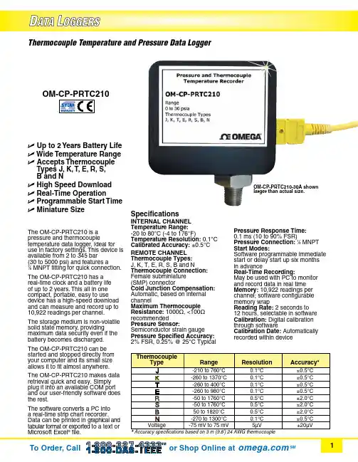
Thermocouple Temperature and Pressure Data LoggerU Up to 2 Years Battery Life U Wide Temperature Range U Accepts Thermocouple Types J, K, T, E, R, S, B and NU High Speed Download U Real-Time OperationU Programmable Start Time U Miniature SizeThe OM-CP-PRTC210 is a pressure and thermocouple temperature data logger, ideal for use in factory settings. This device is available from 2 to 345 bar (30 to 5000 psi) and features a 1⁄8 MNPT fitting for quick connection. The OM-CP-PRTC210 has areal-time clock and a battery lifeof up to 2 years. This all in onecompact, portable, easy to usedevice has a high-speed downloadand can measure and record up to10,922 readings per channel.The storage medium is non-volatile solid state memory, providing maximum data security even if the battery becomes discharged. The OM-CP-PRTC210 can be started and stopped directly from your computer and its small size allows it to fit almost anywhere.The OM-CP-PRTC210 makes data retrieval quick and easy. Simply plug it into an available COM port and our user-friendly software does the rest.The software converts a PC into a real-time strip chart recorder. Data can be printed in graphical and tabular format or exported to a text or Microsoft Excel ® file.SpecificationsINTERNAL CHANNEL Temperature Range:-20 to 80°C (-4 to 176°F)Temperature Resolution: 0.1°C Calibrated Accuracy: ±0.5°C REMOTE CHANNEL Thermocouple Types: J, K, T, E, R, S, B and N Thermocouple Connection:Female subminiature (SMP) connector Cold Junction Compensation: Automatic, based on internal channel Maximum Thermocouple Resistance: 1000Ω, <100Ω recommendedPressure Sensor: Semiconductor strain gauge Pressure Specified Accuracy: 2% FSR, 0.25% @ 25°C Typical Pressure Response Time: 0.1 ms (10 to 90% FSR)Pressure Connection: 1⁄8 MNPT Start Modes:Software programmable immediate start or delay start up six months in advanceReal-Time Recording:May be used with PC to monitor and record data in real time Memory: 10,922 readings per channel; software configurable memory wrapReading Rate: 2 seconds to 12 hours, selectable in software Calibration: Digital calibration through softwareCalibration Date: Automatically recorded within deviceOM-CP-PRTC210-30A shown larger than actual size.OM-CP-IFC200 Windows software displays data in graphical ortabular format.software (required to operate the data logger and is sold separately).To order data logger with NIST calibration certificate, add suffix “-CERT” to model number and add additional cost to price.Ordering Example: OM-CP-PRTC210-30A-CERT, thermocouple temperature and pressure data logger with NIST calibration certificate, and OM-CP-IFC200, Windows software.Battery Type: 3.6 V lithium battery (included), user replaceableBattery Life:Up to 2 years Data Format: Date and timestamped °C, °F, K, °R, °C, °F, °K,°R, mV; inH2O, psig, inHg, bar, atm, Torr, Pa, kPa, and MPa Time Accuracy:±1 minute/month (at 20 to 30°C)Computer Interface: PC serial or USB (interface cable required); 57,600 baud5SRTC/5LRTC Series. Software: XP SP3/Vista/7 and 8 (32-bit and 64-bit)Operating Environment: -20 to 80°C (-4 to 176°F), 0 to 95% RH non-condensing Dimensions:55 H x 63 W x 22 mm D (2.2 x 2.5 x 0.9") plus NPT fittingEnclosure: Delrin ®Weight: 119 g (4.2 oz)。

Copyright © 2011 Pico Technology Ltd. All rights reserved.PicoLog CM3User's Guideplcm3.en-2Current Data LoggerI PicoLog CM3 Current Data Logger User's GuideContents1 Introduction (1) (1)1 Overview (2)2 Safety warnings (3)3 Standards compliance (3)4 Warranty (4)5 Legal information (5)6 Minimum PC requirements2 Product information (6) (6)1 Pack contents (6)2 Connections (8)3 Ethernet setup utility (9)4 Setting up (12)5 Specifications (13)IndexPicoLog CM3 Current Data Logger User's Guide1 1Introduction1.1OverviewThe PicoLog CM3 is a three-channel, high-resolution currentdata logger for monitoring current on up to three channels.With high accuracy and low noise, the PicoLog CM3 is idealfor recording data from three-phase supplies. The USB andEthernet interfaces allow the logger to be used as a USB-onlydevice, as a USB-powered device with Ethernet interface, oras a Power-over-Ethernet (PoE) device. Using the Ethernetinterface, the PicoLog CM3 can be located anywhere on aLAN or on the internet.Programmer's GuideAll the software that you need for everyday use of the PicoLog CM3 is supplied withthe unit. For more advanced applications, you can write your own software.Information on programming is published in a separate guide:PicoLog CM3 Data Logger Programmer's Guide (plcm3pg.en.pdf)Driver InstallationThe driver was installed automatically when you installed PicoLog Recorder software.Alternatively, you can download the driver from our website at http://www.picotech.com.2Introduction 1.2Safety warningsWe strongly recommend that you read the general safety informationbelow before using your product for the first time. If the equipment is notused in the manner specified then the protection provided may beimpaired. This could result in damage to your computer and injury toyourself and others.DO NOT exceed the maximum input range. The PicoLog CM3 is rated to measurevoltage up to 1 V RMS, while the supplied clamps have a range of 0 to 200 A. Anysignal in excess of these values may cause permanent damage to the unit and/or theclamps.DO NOT rely on the product to provide a protective safety earth. The unit doesnot have a protective safety earth.DO NOT attempt to repair the unit. The unit contains no user-serviceable parts.Repair or calibration of the unit requires specialised test equipment and must beperformed by Pico Technology or its authorised distributors.DO NOT attempt to feed current directly through the unit. You must use avoltage-output current clamp.DO NOT attempt to use a current transformer directly. You must use a voltage-output current clamp.DO NOT install a current clamp over any live, exposed conductors. You mustnot make an electrical connection to the conductor, as doing so may be dangerousand could cause damage to the equipment, your computer and may cause injuries toyourself and others. The TA138 clamps supplied with the PicoLog CM3 are suitable forwork on uninsulated high-voltage cables. You MUST ensure that appropriate safetyprecautions have been made in order to isolate the cable you wish to clamp beforefitting takes place. When using alternative current clamps, you should check theirsuitability for this usage.PicoLog CM3 Current Data Logger User's Guide31.3Standards complianceThis page details the standards to which the PicoLog CM3 and/or TA138 current clamp currently meets.FCC ClassificationThis equipment has been tested and found to comply with the limits for a Class Adigital device, pursuant to Part 15 of the FCC Rules. These limits are designed toprovide reasonable protection against harmful interference when the equipment isoperated in a commercial environment. This equipment generates, uses, and canradiate radio frequency energy and, if not installed and used in accordance with theinstruction manual, may cause harmful interference to radio communications.Operation of this equipment in a residential area is likely to cause harmful interference in which case the user will be required to correct the interference at his or her ownexpense.For safety and maintenance information see the safety warning.IEC standardThe supplied TA138 clamps comply with the following standards: IEC1010-1 (1995)Category II 600 V, and Category III 300 V.CE standardThe PicoLog CM3 Data Logger meets the intent of the EMC directive 89/336/EECand has been tested to EN61326-1:2006 Class A Emissions and Immunitystandard.The product also meets the intent of the Low Voltage Directive and has beendesigned to meet the BS EN 61010-1:2010 Safety requirements for electricalequipment for measurement, control, and laboratory use standard.The supplied TA138 clamps comply with the following standards: EN61010-1 (2001)Category II 600 V, and Category III 300 V.1.4WarrantyPico Technology warrants upon delivery, and for a period of 5 years unless otherwise stated from the date of delivery, that the Goods will be free from defects in materialand workmanship.Pico Technology shall not be liable for a breach of the warranty if the defect has beencaused by fair wear and tear, willful damage, negligence, abnormal working conditions or failure to follow Pico Technology's spoken or written advice on the storage,installation, commissioning, use or maintenance of the Goods or (if no advice hasbeen given) good trade practice; or if the Customer alters or repairs such Goodswithout the written consent of Pico Technology.Introduction 41.5Legal informationThe software supplied with this product is licensed, not sold. Pico Technology Limitedgrants a licence to the person who installs this software, subject to the conditionslisted below.Access. The licensee agrees to allow access to this software only to persons whohave been informed of these conditions and agree to abide by them.Usage. The software in this release is for use only with Pico products or with datacollected using Pico products.Copyright. Pico Technology Limited claims the copyright of, and retains the rights to, all material (software, documents etc.) contained in this release. You may copy anddistribute the entire release in its original state, but must not copy individual itemswithin the release other than for backup purposes.Liability. Pico Technology and its agents shall not be liable for any loss, damage orinjury, howsoever caused, related to the use of Pico Technology equipment orsoftware, unless excluded by statute.Fitness for purpose. Because no two applications are the same, Pico Technologycannot guarantee that its equipment or software is suitable for a given application. Itis your responsibility, therefore, to ensure that the product is suitable for yourapplication.Mission-critical applications. This software is intended for use on a computer thatmay be running other software products. For this reason, one of the conditions of thelicence is that it excludes usage in mission-critical applications; for example, life-support systems.Viruses. This software was continuously monitored for viruses during production, butyou are responsible for virus-checking the software once it is installed.Support. If you are dissatisfied with the performance of this software, please contactour technical support staff, who will try to fix the problem within a reasonable time. Ifyou are still dissatisfied, please return the product and software to your supplierwithin 14 days of purchase for a full refund.Upgrades. We provide upgrades, free of charge, from our web site at www.picotech.com. We reserve the right to charge for updates or replacements sent out on physicalmedia.Trademarks. W indow s is a registered trademark of Microsoft Corporation in the USAand other countries. Pico Technology Lim ited, and PicoLog are trademarks of PicoTechnology Limited registered in the United Kingdom and other countries.PicoLog CM3 Current Data Logger User's Guide 51.6Minimum PC requirementsTo ensure that your PicoLog CM3 operates correctly, you must have a computer withat least the minimum system requirements to run one of the supported operatingsystems, as shown in the following table. The performance of the data logger will bebetter with a more powerful PC.ItemSpecification Operatingsystem Windows XP SP2Windows VistaWindows 732 bit and 64* bit versions supportedProcessorAs required by Windows MemoryFree diskspacePorts USB and optional Ethernet ports* While the driver will run on a 64 bit operating system, the driver itself is 32 bit, and therefore will run as 32 bit.Product information 62Product information2.1Pack contentsPlease check that your PicoLog CM3 pack contains the following items:PP803Quantity Reorder code Description1PR136PicoLog CM3 Current Data Logger3TA138AC current clamp1MI106USB lead1TA076Ethernet patch cable1DI025Software and Reference CD1DO112USB Installation GuidePP815Quantity Reorder code Description1PR136PicoLog CM3 Current Data Logger1MI106USB lead1TA076Ethernet patch cable1DI025Software and Reference CD1DO112USB Installation Guide2.2ConnectionsImportant:Do not connect your PicoLog CM3 to the PC untilyou have installed the software.DiagramsA:Signal and ground* connection sockets for current clamp 1B:Signal and ground* connection sockets for current clamp 2C:Signal and ground* connection sockets for current clamp 3D:Ethernet portE:USB portF:Ethernet Data indicator - Flashes to indicate Ethernet data transfer.G:Ethernet Link indicator - On when Ethernet port connected to an active device.H:Power/Status indicator - On when power is applied. Flashes to indicate conversion in progress.*Ground is provided via electrical connection to the USB groundPicoLog CM3 Current Data Logger User's Guide7 USB connectionTo use the PicoLog CM3 with its USB connection, connectthe USB port on the rear of the device to a USB port onyour computer using the cable provided.The first time you connect the device, Windows will installthe driver and then tell you that the device is ready foruse. You can then run PicoLog Recorder software to startmaking measurements.Ethernet port connectionBefore connecting to the PicoLog CM3's Ethernetport, you must first configure the Ethernet settings.LAN connectionTo use the PicoLog CM3 on a local-area network (LAN),connect it to your network switch or network router usingthe Ethernet cable provided.Direct connectionYou can also connect the PicoLog CM3 directly to thenetwork port on your computer. For this connection, youwill need to use an Ethernet crossover cable (notsupplied).Power over Ethernet (PoE)The PicoLog CM3 can obtain its power from the Ethernetport as a Powered Device (PD) according to the PoEstandard (802.3af). To use this feature, you must connectthe unit to Power Sourcing Equipment (PSE) such as anetwork switch, router or power injector that also supportsthe PoE standard. Any standard Ethernet cable up to100 m (about 328 ft) in length can be used.Current clamp connectionThe PicoLog CM3 is compatible with Pico TechnologyTA138 current clamps.Each current clamp has both a red and a black 4 mmconnector, which plug directly into the red and blackconnections on the front panel of the PicoLog CM3.Once the current clamp(s) are connected, they are easilyfitted around a supply cable by use of the lever on edge ofthe clamp.8Product information 2.3Ethernet setup utilitySetup utility1.Connect the unit to your computer using the USB port.2.Run the Ethernet Settings utility. There is a shortcut to this utility in the PicoTechnology program group under the Windows Start menu.3.Set the Device Types control to "PicoLog CM3".4.The serial number of your device should appear in the device list. Click the deviceonce to select it.5.Set the Enable Ethernet Settings check box.6.Enter the IP address and port that you wish to give the device. You may need toask your network manager for an IP address that does not conflict with existingdevices on the network.7.Click Save.8.You can now either continue to use the PicoLog CM3 as a USB device, or unplugthe USB cable and reconnect the device using its Ethernet port.Power-saving tipIf you wish to stop using the PicoLog CM3 in Ethernet mode, you can usethe Ethernet Settings utility to disable its Ethernet port. This reduces thepower consumption of the device when used in USB mode.Ethernet and USBDo not use the PicoLog CM3 in USB mode when it is being powered byPower-over-Ethernet (PoE). This could cause the unit to radiateelectromagnetic energy outside the limits permitted by FCC and EUregulations, and could also cause it to produce spurious measurements. Itwill not, however, cause permanent damage to the unit.PicoLog CM3 Current Data Logger User's Guide92.4Setting upSet up the PicoLog CM3 as follows:1.From the File menu in the PicoLog Recorder software, select New settings.The Recording dialog box appears:2.Click OK. The Sampling Rate dialog box appears:3.Click OK. The Converter details dialog box appears.4.From the Converter type drop-down list, select either PLCM3 (USB) or PLCM3(Ethernet). The dialog box will then show the converter list, as shown below:Product information 10B connection: Select the device with the correct type and serial number, andclick OK.Ethernet connection: Any PicoLog CM3 devices visible to your computer onyour local network will appear in the list. Select the device with the correct type,serial number and IP address, and click OK. If your device does not appear in thelist, type its IP address and port number in the boxes below the list.When you click OK, the PicoLog CM3 channels window will appear:6.In the PicoLog CM3 channels window, double-click on Ch1 unused. The EditPicoLog CM3 Channel dialog box appears:7.Type in a name for the channel, if required.8.Select the data type required i.e 1 mV/A, 10 mV/A , 100 mV/A, or Voltage.PicoLog CM3 Current Data Logger User's Guide119.Now click OK. Readings from the PicoLog CM3 will appear in the monitor window:Product information 122.5SpecificationsPicoLog CM3 Current Data Logger User's Guide13IndexAAccess 4Accuracy 12CConnectionEthernet 8LAN 8USB 6Connectors 12Conversion time 12 Copyright 4DDimensions 12EEnvironmental conditions 12 Ethernetconnection 8FFitness for purpose 4IInputsimpedance 12number of 12LLegal information 4Liability 4Linearity 12MMains voltages 2Maximum input range 2 Mission-critical applications 4NNoise, RMS 12OOutput 12Overview 1Overvoltage protection 12PPack contents 6PC requirements 5Power-over-Ethernet (PoE) 8RRange 12Repairs 2Resolution 12SSafetywarning 3Safety warnings 2Sensor 12Setting up 9Software 12Specifications 12Support 4TTrademarks 4UUpgrades 4Usage 4USB 5connection 6VViruses 4WWarranty 3PicoLog CM3 Current Data Logger User's Guide15Pico TechnologyJames HouseColmworth Business ParkST. NEOTSCambridgeshire PE19 8YPUnited KingdomTel: +44 (0) 1480 396 395Fax: +44 (0) 1480 396 296Copyright © 2011 Pico Technology Ltd. All rights reserved.plcm3.en-228.06.11。

1、压力校验仪在使用时,请将仪器拧入手操压力泵上“标准仪表"接口。
压力校验仪
2、快接头用所配高压软管连接被检仪器即可校验。
3、电源开、关键:按“开"键打开,LCD 显示测量状态;按“关"键,仪表关机,切断电源。
4、校零键:测量前,按一下:“校零"键,仪表自动将传感器的零点数值采集并送处理器CPU进行处理,保证仪表所测数据为实际压力值。
5、压力键:开机后LCD右下角显示该仪表的压力单位,若使用中按“单位"键、使LCD显示为“Psi、Bar、mmHg、Kgf/cm2"中任何一种单位时,按一下“压力"键,仪表自动切换到出厂时设置压力单位档上。
需要显示测量电流时,在仪表显示单位为MPa(或KPa)时,按一下“压力"键,面板上对应的电流指示灯亮,即为测量电流状态。
压力校验仪的压力量程与压力泵的配置:压力校验仪的压力量程根据用户的要求配置,如果的带真空的压力校验仪,压力量程最大在-95KPa~2.5MPa,这款压力校验仪只需要配置内置式压力泵,一般0~6MPa以内的压力校验仪都可以配置内置式压力表,而超过这个量程的压力就需要配置外置泵了。
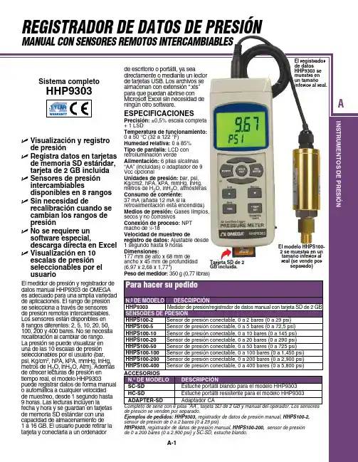

Milog3压力记录仪使用说明书北京恒泰士仪表有限公司北京恒泰士仪表有限公司北京市海淀区北四环中路209号海科创业大厦5401室电话:086-010-********传真:086-010-********一、前言1.1、前言请在使用仪表前先仔细阅读本说明书。
1.2、配件清单HS610配置清单:配件名称数量有/无Milog3主机 1台1/4 Npt接头转1/2Npt管螺纹接头 1个USB下载线 1台U盘 1个通讯线 1条选配光盘 1片说明书 1本合格证 1张(表1)1.3、注意事项用户打开仪表包装后,请先检查仪表外观是否有损坏,接着再检查仪表的型号是否与您的定货相符,若出现上述问题请立即与本公司联系更换。
请在了解了仪表的接线和操作后再测试或者安装仪表。
请在仪表允许的工作条件下使用仪表。
一般情况下用户不要擅自拆开仪表,以免发生意外损坏;如仪表出现故障,请先与本公司技术人员联系,在技术人员允许和指导下方可拆开仪表。
请不要用有机溶液清洗LCD屏幕,以免损伤屏幕。
仪表每年应进行一次计量检定,如果仪表误差超出范围,通常都是由于潮湿、灰尘或腐蚀气体所导致,可对仪表内部进行清洁及干燥处理,通常这样就能解决问题。
如仍不能解决问题请与本公司技术人员联系。
二、概述2.1、主要特点l 无纸化、低功耗,采用普通锂电池供电。
l 体积小、集成度高、便于安装l 现场液晶显示实测压力值,当前时间等l 压力或者温度记录时间间隔:1秒--24小时l 记录最多达10年的历史压力数据l 内置大容量存储器存储数据,每个压力或者温度通道可存储100万个数据。
l 通用U盘读取数据l 支持modbus通讯协议2.2、技术指标l 环境温度:-20~60℃l 被测介质:天然气,自来水等非腐蚀性介质l 压力精确度:0.5级l 防水等级:IP65l 防爆等级:本安防爆l 通讯响应时间:≤50msl 报警功能:上限、上上限、下限、下下限等4种方式,最多可带2路报警输出l 内置锂电池供电,寿命不短于3年l 环境湿度:<85%RH2.3、型号定义仪表的型号定义如下:(表2)三、仪表安装3.1、安装环境环境温度:0℃-50℃;环境湿度:10%-85%(无结露)。
U Temperature Range: -20 to 85°C (-4 to 185°F)U Pressure Ranges: 35, 150, 350, 550, 2000, 5800 psiaU Vacuum Ranges: 760 and 380 TorrU 150% Over Range ProtectionU Programmable Start/Stop Time and Sample RatesU Up to 64,000 Samples Per RecordU Alarm Set PointsU Rugged IP67 Package U Five Year Battery LifeU High Accuracy and Repeatability The OM-PR Series pressure/temperature data loggers are battery powered stand alone water tight compact data loggers that record up to 64,000 samples of pressure and/or temperature data. These data loggers can be configured to record pressure and temperature or a parameter alone to maximize data storage space.The unit is easily configured using the included Windows ® software. Simply connect a standard USB cable to the logger and an open USB port on your PC and the Windows software automatically identifies the data logger. Configure the unit to start and stop recording at a predetermined time and date or only when an alarm condition is sensed. The sample storage rate can be set from 1 sample every 2 seconds up to 1 sample every 24 hours. The on board data storage is non-volatile so data will not be lost in the event of a depleted battery.The OM-PR Series pressure/temperature data loggers are available in several pressure (0 to 35, 0 to 150, 0 to 350, 0 to 550, 0 to 2000, 0 to 5800 psia) and vacuum (760 and 380 Torr) ranges. The data logger is packaged in a rugged submersible 316L stainless steel housing and has a standard 1⁄4 NPT fitting. The replaceable internal lithium battery has up to a 5 year life.The Windows software is a powerful data acquisition package and is included with every OM-PR Series data logger. It allows for easy setup, retrieval, interpretation and export of the recorded data. Simply connect your data logger to an open USB port and begin communicating immediately.Choose absolute or gauge readings, as well as your pressure scale from a list that includes kP A, MP A, Bar, milliBar, mmHG, Atm, PSI, pascal, inH 2O and torr. Record the average, instantaneous, maximum, or minimum pressure during your sample interval. Point and click to select your sample interval, alarm set points, engineering units and recording triggers.View a numerical data table or graphical representation of data readings relative to time. Use the graph tools such as zoom, cursor, min and max to examine and analyze the record. The Windows software turns your PC into a real time data acquisition system by allowing you to stream graphical or tabular data directly to your PC. Stored data can be exported into an Excel spreadsheet.OM-PR150 with cover removed shown larger than actual size.Windows software (included) turns your PC into a real time data acquisition system.Ordering Example: OM-PR150-NIST, pressure/temperature data logger, 150 psia range with NIST calibration certificate and OCW-1, OMEGACARE SM extends standard 1-year warranty to a total of 2 years.Specifications PRESSURE Pressure Ranges: 0 to 35, 0 to 150, 0 to 350, 0 to 550, 0 to 2000, 0 to 5800 psia Vacuum Ranges: 760 T orr, 380 T orr Accuracy: ±1% Resolution: 0.01 psia Repeatability: ±0.05% Overpressure Rating: 1.5 times maximum Port Connection: 1⁄4 NPT male TEMPERATURE Temperature Range: -20 to 85°C (-4 to 185°F) Accuracy: ±1°C, 0 to 50°C (32 to 122°F); ±2°C, -20 to 85°C (-4 to 185°F) Resolution: 0.1°C (0.1°F) GENERAL Record:S ample Rate: User configured 1 every 2 seconds to 1 every 24 hoursN umber of Samples: 32,000 or 64,000 (depends on setup) Record Trigger: Two independent triggersM ultiple Trigger Modes: Instantaneous, button control, on alarm, time and date (start and stop), day of week R ecord Mode: Fill to end of memory or cyclic, number of samples and time duration Alarms: 2 user programmable alarms, high or low Communication: Direct USB connection Software: Windows 2000/XP/Vista/7 and 8 (32-bit and 64-bit)Battery Type: 1/2AA, 3.6V , 1.2Ah lithium battery (included) Battery Life: Up to 5 years typical @ 1 minute sample rateEnclosure: Material: 316L stainless steel D imensions (Excludes Port Thread): 5.6 H x 5 cm dia (2.19 x 1.95")Weight: 0.9 kg (2.0 lb)Detail of OM-PR150 with cover removed.。
MiLog3双通道压力记录仪使用手册1、产品概括Milog3-2P压力记录仪专门对管道或压力容器进行压力监测的电子数据记录装置。
它集传感器、智能仪表于一体,能够按照设定的压力记录时间间隔采集、记录压力数据。
用户可以通过U盘转储数据,在电脑上通过本公司提供的上位机数据管理软件对数据进行列表、雷达图、二维曲线显示,数据导出到Execl,提供常规的压力上下限报警,震荡报警,也可根据用户需求,定制分析算法。
Milog3系列压力记录仪采用Modbus RTU通讯协议,通过RS485/232接口传输给显示仪、调节器、DCS 等,集成到scada系统中。
该款双通道压力记录仪,广泛应用于燃气调压站前后压力记录,分析调压器运行过程中是否出现故障,有效的分析出调压器运行压力高,运行压力低,调压器喘动,小流量压力高等常见故障,给出相应的检修方案,协助用户完成调压器维护。
2、主要特点(1)无纸化、低功耗,采用锂电池供电;(2)体积小、集成度高、便于安装(3)现场液晶显示实测压力值,当前时间等(4)压力或者温度记录时间间隔:1秒--24小时(5)记录最多达10年的历史压力数据(6)内置大容量存储器存储数据,每个压力或者温度通道可存储50万个数据。
(7)通用U盘读取数据(8)支持modbus通讯协议3、技术指标(1)环境温度:-20~60℃(2)被测介质:天然气,自来水等非腐蚀性介质(3)压力精确度:0.5级(4)防水等级:IP65(5)防爆等级:本安防爆(6)通讯响应时间:≤50ms(7)报警功能:上限、上上限、下限、下下限等4种方式,最多可带2路报警输出(8)内置锂电池供电,寿命不短于3年(9)环境湿度:<85%RH4、液晶显示符号说明1、记录仪配置软件的使用记录仪的通用信息包括系统配置,液晶显示,启停切换记录等。
设备编号:仪表设备与上位机通讯的唯一关键字。
“打压版本”中,“设备编号”默认为“1”,不可修改;“监控版本”中,被设定为modbus通讯地址;设备名称:用户可以按照设备安装地点、用途等需要,设定小于10个英文字母或数字的设备名称名称信息。
压力自动记录仪操作规程
1、特点:
适用于煤气、天然气等气体的生产、供应或煤气配气站和管网部门对气体压力值的测量和监视,并对24小时内气体压力的波动情况进行连续记录。
二、操作方式:
1)记录仪垂直安装在墙壁等可靠的地方,安装位置应便于维修、检修和观察读数,管理和记录仪进行气接头相联;
2)打开表盖,用专钥匙给钟表机芯上满发条;
3)逆时针方向拧下压纸帽,装入记录纸,记录笔尖对正记录纸时逆时针轨迹,然后拧紧压纸帽,但不可过分用力,以免损坏钟表机芯;
4)检查记录笔尖是否对正记录低零点,不对时,可调节调零螺钉,调到零点;
5)若笔尖接触不到记录纸,请调节滚花螺母,注意不可弯曲笔杆;6)关上表盖,接通气源,仪表即可进行工作。
三、注意事项:
1、记录仪使用泡沫自动记录笔的笔尖,一只泡沫笔大约可使用40天左右,如无墨水,可加注专用墨水,可加注专用墨水,或更换墨水,或更换笔尖。
特别注意:更换笔尖时,先关闭气源,使记录仪内气压为零,再将新笔尖插入笔杆底部,重新调整调零螺钉,使笔尖对准记录纸零位,笔杆不可随意弯曲,否则影响记录精度;
2、记录纸每24小时进行更换;
3、记录仪不可超压使用;。
压力记录仪安全操作及保养规程1. 引言压力记录仪是一种常见的测试仪器,广泛应用于各种工业领域和实验室环境中。
它可以用来测量和记录介质的压力变化,帮助工程师和技术人员监测机器设备的工作状态,并及时发现和解决问题。
但是,对于初次使用压力记录仪的用户来说,正确的操作和保养也是非常重要的,否则可能导致安全隐患或影响测试结果的准确性。
本文将介绍压力记录仪的安全操作和保养规程,帮助用户正确使用和维护该设备。
2. 安全操作规程2.1. 设备准备使用压力记录仪前,需进行以下准备工作:•确保设备电源插头与插座相匹配,电源电压符合设备要求。
•检查传感器和连接器是否完好,并严格按照设备说明书插拔连线。
•验证设备是否选择正确的启动方式,如自动或手动设置启动方式等。
2.2. 操作规程采集数据时,需遵守以下操作规程:•确认设备已正确连接监控介质,符合测试要求。
•启动系统前,保证传感器与介质相连接,并在无负荷状态下进行检查。
•避免系统中出现超压和超载等异常情况。
如果发现较大的压力脉冲或瞬时冲击,需查找并解决问题后再次采集数据。
•当设备采集到数据时,要小心操作,避免将设备碰撞或摔落。
•采集结束后,将设备安放在干燥的环境中。
注意不要放在受热、压力或潮湿的地方。
2.3. 设备维护正确的维护步骤可以延长设备的使用寿命,保证数据采样的准确性和可靠性。
以下是设备维护规程:•定期进行对设备固件的升级,保持设备最新的状态、修复已知的漏洞和问题。
•清理传感器、连接器、和仪器表面,避免进入杂质、灰尘、油渍或腐蚀性物质。
•当采集结束后,离线设备前,务必保护仪器表面,并定期进行清理和消毒。
•后续存储和分析过程中,需要根据需要对数据加密或添加鉴别信息,防止数据被非法的第三方访问。
同时也需要将设备固件和数据备份,以备日后出现意外状况时进行恢复。
3. 总结压力记录仪的正确使用和保养对于保证测试数据的准确性和设备的安全性都是必不可少的。
如果你是初次使用压力记录仪的用户,建议仔细阅读设备说明书,严格按照设备操作规程进行操作,保养设备并避免设备发生损坏或失效。
e-mail:**************For latest product manuals:omegamanual.infoOM-CP-PRHTemp2000Pressure, Humidity and Temperature Data Logger with LCDShop online at MADE INOM-CP-PRHTemp2000Product NotesThe OM-CP-PRHTemp2000 is a pressure, temperature and humidity data logger with LCD display. The convenient LCD provides access to the current pressure, temperature and humidity readings, as well as minimum, maximum and average statistics.For additional information refer to your OM-CP-PRHTemp2000 manual and “Data Logger & Software Operating Manual”.BacklightThe backlight uses a significant amount of battery life. Refer to the manual to configure the auto shut-off when not in use.Set PasswordTo password protect the device so that others cannot start, stop or reset the device:- Click Identify Device and Read Status, then select the Device Detail Tab.- Choose Set Password.- Enter and confirm the password and click OKDevice MaintenanceBattery ReplacementMaterials:3/32” HEX Driver (Allen Key) and a Replacement Battery (OM-CP-BAT103)- Remove the back cover from the device by unscrewing the four screws.- Remove the battery from its compartment and unsnap it from the connector. - Snap the new battery into the terminals and verify it is secure.- Replace the cover taking care not to pinch the wires. Screw the enclosureback together securely.Note: Be sure not to over tighten the screws or strip the threads.Quick Start ManualInstallation GuideInstalling the Interface cable- OM-CP-IFC200: Insert the Software CD in the CD-ROM Drive. If the autorun does not appear, locate the drive on the computer and double click onAutorun.exe. Click on Drivers and Third Party Tools, then Install USBInterface Drivers. Click Install to install the USB drivers. Plug theOM-CP-IFC200 cable into an available USB port on the computer.Installing the softwareInsert the Software CD in the CD Drive. If the autorun does not appear, locate the drive on the computer and double click Autorun.exe. Follow the instructions in the Wizard.Connecting the data logger- Once the software is installed and running, plug the interface cable into the data logger.- Click the Communication Menu, then Auto Configure Port.- After a moment, a box will appear stating that a device has been found.- Click OK. The Device Status box will appear. Click OK.- At this point, communications have been configured for your logger. These settings can be found under the Communication Menu.Note: For additional installation instructions refer to your “Data Logger & Software Operating Manual”.Device OperationStarting the data logger- Click Device Menu then Start Device.- Choose the desired start method.- Choose the start parameters by selecting a Reading Rate suitable for yourapplication.- Enter in any other desired parameters and click Start.- A box will appear stating the data logger has been started. Click OK.- Disconnect the data logger from the interface cable and place it in theenvironment to measure.Note: The device will stop recording data when the end of memory is reached or the device is stopped. At this point the device cannot be restarted until it has been re-armed by the computer. Downloading data from a data logger- Connect the data logger to the interface cable.- Click the Device Menu then Read Device Data. This will offload all recorded data onto the PC.Battery WarningWARNING: FIRE, EXPLOSION, AND SEVERE BURN HAZARD. DO NOT SHORT CIRCUIT, CHARGE, FORCE OVER DISCHARGE, DISASSEMBLE, CRUSH, PENETRATE OR INCINERATE. BATTERY MAY LEAK OR EXPLODE IF HEATED ABOVE 60°C (140°F).。
Milog3压力记录仪使用说明书北京恒泰士仪表有限公司北京恒泰士仪表有限公司北京市海淀区北四环中路209号海科创业大厦5401室电话:086-010-********传真:086-010-********一、前言1.1、前言请在使用仪表前先仔细阅读本说明书。
1.2、配件清单HS610配置清单:配件名称数量有/无Milog3主机 1台1/4 Npt接头转1/2Npt管螺纹接头 1个USB下载线 1台U盘 1个通讯线 1条选配光盘 1片说明书 1本合格证 1张(表1)1.3、注意事项用户打开仪表包装后,请先检查仪表外观是否有损坏,接着再检查仪表的型号是否与您的定货相符,若出现上述问题请立即与本公司联系更换。
请在了解了仪表的接线和操作后再测试或者安装仪表。
请在仪表允许的工作条件下使用仪表。
一般情况下用户不要擅自拆开仪表,以免发生意外损坏;如仪表出现故障,请先与本公司技术人员联系,在技术人员允许和指导下方可拆开仪表。
请不要用有机溶液清洗LCD屏幕,以免损伤屏幕。
仪表每年应进行一次计量检定,如果仪表误差超出范围,通常都是由于潮湿、灰尘或腐蚀气体所导致,可对仪表内部进行清洁及干燥处理,通常这样就能解决问题。
如仍不能解决问题请与本公司技术人员联系。
二、概述2.1、主要特点l 无纸化、低功耗,采用普通锂电池供电。
l 体积小、集成度高、便于安装l 现场液晶显示实测压力值,当前时间等l 压力或者温度记录时间间隔:1秒--24小时l 记录最多达10年的历史压力数据l 内置大容量存储器存储数据,每个压力或者温度通道可存储100万个数据。
l 通用U盘读取数据l 支持modbus通讯协议2.2、技术指标l 环境温度:-20~60℃l 被测介质:天然气,自来水等非腐蚀性介质l 压力精确度:0.5级l 防水等级:IP65l 防爆等级:本安防爆l 通讯响应时间:≤50msl 报警功能:上限、上上限、下限、下下限等4种方式,最多可带2路报警输出l 内置锂电池供电,寿命不短于3年l 环境湿度:<85%RH2.3、型号定义仪表的型号定义如下:(表2)三、仪表安装3.1、安装环境环境温度:0℃-50℃;环境湿度:10%-85%(无结露)。
避免太阳光直射,及安装在有蒸汽、腐蚀性气体、电磁发生源的地方。
3.2、安装尺寸(图1)3.3、安装方法HS-6压力记录仪通过螺纹接口与引压管相连,连接处需安装仪表针阀,方便仪表调试、更换和维修。
应尽量使测量安装点避免环境因素的干扰,如剧烈的温度变化、振动和冲击等。
HS-6压力记录仪的管螺纹接口为1/4Npt形式,提供两种转换接口,1/4Npt转1/2Npt和1/4Npt转M20*1.5;目前推荐两种安装方式:①压力记录仪直接与仪表针阀相连接;②压力记录仪安装在墙装支架上,然后通过压力取样管,通过卡套接头安装。
1、直接连接直接连接时仪表针阀接口允许通过转接头与两种螺纹接口连接,公制螺纹M20×1.5和1/2NPT螺纹。
安装步骤如下:1)当仪表针阀接口为M20×1.5时Ⅰ将仪表针阀安装在管道的取压接头上,确保密封良好,仪表针阀处于关闭状态;Ⅱ安装压力记录仪,压力记录仪接口与截止阀接口之间通过密封垫片密封;Ⅲ打开截止阀,观察压力记录仪的示值。
2)当仪表针阀接口为1/2NPT时(图2)Ⅰ选取1/2NPT螺纹转接头,安装在压力记录仪接口上;Ⅱ将仪表针阀安装在管道的取压接头上,确保密封良好,仪表针阀处于关闭状态;Ⅲ安装压力记录仪,压力记录仪接口与仪表针阀接口之间缠绕生胶带,保证密封良好;Ⅳ打开仪表针阀,观察压力记录仪的示值。
2、支架安装Ⅰ确定压力记录仪的安装位置,固定压力记录仪;Ⅱ按照压力记录仪安装位置与取压点的距离及现场设备分布,确定导管走向及长度;Ⅲ检查取压点的密封性是否良好;Ⅳ选用外径为φ6的不锈钢管作引压管进行弯制;Ⅴ连接引压管与压力记录仪卡套接口;Ⅵ检查密封性,打开针阀,观察压力记录仪示值。
图33.4、接线说明1、RS-232通讯数据线通讯数据线和电脑通过串口连接后,完成记录仪的参数配置、量程校准、历史数据下载等操作,取下MinUsb接口防尘罩,将数据线接入仪表底端的MinUsb接口。
本数据线为专用通讯电缆。
HS-6系列数据记录仪内置Modbus协议,通过RS-232接口,可和通用组态软件连接,建立实时的SCADA监控系统。
2、USB转MinUsb转换线将U盘连接到USB转换线,经转换线连接到记录仪上,完成历史数据下载。
HS-610会在U盘上建立”LogDat”文件夹,建立的数据以记录仪编号为文件名称保存,如记录仪编号为“1001”,则建立的数据文件为“U盘\Logdat\1001.dat”。
提供多种数据分析软件,可用于管道气密性检验、调压器故障判断、压力越限检测等。
四、操作指南4.1、面板按键说明1、切换显示内容液晶面板在没有操作的情况下,是处于休眠状态,当按下按键后,液晶被激活,按键每按一次,依次循环的切换一项显示内容。
液晶所显示的内容主要包括下图所示,如果被选中“”,则在按键切换的时候出现该项。
配置方法请参看软件说明部分。
(图4)2、液晶显示符号说明(表3)3、启动USB数据下载UTG(USB下载模块)外置方式:在一些不方便操作人员进入的场合,如防爆区域,狭小空间等。
可以采用UTG方式,通过UTG延长线,将数据下载延长至8米以内的区域。
支持USB数据转储到USB电子盘功能的记录仪,连接好UTG模块,工作指示灯(红色)发光,插好USB移动盘,可以通过按下按键6秒后,启动转储,液晶面板提示操作进度,完成后,液晶进入休眠,UTG模块,工作指示灯灭,即可拔下UTG模块,完成操作。
4、UTG内置方式将U盘通过数据线连接到记录仪上,按下按键,持续6秒钟,液晶面板显示下载指示操作,待精度指示显示“USB OK”,就可以取下U盘,完成下载。
下载显示信息参看表3。
五、记录仪配置软件使用5.1、通用信息配置记录仪的通用信息包括系统配置,液晶显示,启停切换记录等。
(图5)Ø设备编号: 仪表设备与上位机通讯的唯一关键字。
“打压版本”中,“设备编号”默认为“1”,不可修改;“监控版本”中,被设定为modbus通讯地址;Ø设备名称:用户可以按照设备安装地点、用途等需要,设定小于10个英文字母或数字的设备名称名称信息。
Ø版本信息:分成三个版本;“打压:V4.2”表示管道气密性检测系统,目前最高版本为4.2.“监控:V3.5”,表示用于调压站站控系统的检测、控制、传输为一体的RTU终端。
“调压箱:V5.8”,用于调压箱内压力,温度等数据记录,定期使用USB磁盘读取数据。
供用户将运行数据备案,可取代纸式“圆盘记录仪”。
Ø输入和输出通道:表示记录仪内部支持的模拟量和开关量数据;AI:* :表示模拟量输入通道,表示压力、温度等记录信息;AO:* :表示模拟量输出通道数量;DI:* :表示开关量输入通道数量;DO:* :表示开关量输出通道数量;Ø内存空间:决定记录仪存储数据记录条数的多少,分成2MBYTE、4MBYTE、8MBYTE;根据模拟量通道数量,将存储区等量分配给模拟通道,从而决定每个通道的记录数量;具体信息请参考下表。
内存空间 AI数量记录条数等效记录周期(1秒)等效记录周期(5分钟)2MBYTE1/2 524288 6天 5年3/4 262144 3天 2.5年4MBYTE1/2 1048576 12天 10年3/4 524288 3天 5年(表6)Ø通讯速率:默认为9600bps。
用户不可自行修改;Ø校对时间:记录仪有校对时间和当前时间之分,校对时间是记录仪和上位机之间的时间同步时,配置的时间;当前时间,是指记录仪的工作时间。
Ø系统状态:分成“运行”和“停止”,系统校对时间后,系统状态自动变成停止状态,停止状态下,记录仪不记录历史数据;只有记录仪处于运行状态,才开始按照记录间隔所设定的时间,定时记录数据到存储器中。
Ø显示信息:确定了记录仪液晶面板数码管上显示的内容,图4说明的是除了低压力通道信息不显示外,其他的几个内容都在液晶面板上轮询显示。
(图7)5.2、启停切换记录记录仪在运行过程中,可以多次进行“启动/停止”操作,只记录“运行”状态时间段内的数据,不记录“停止”时间段内的数据。
(图8)“启动/停止”操作属于管理权限,所以必须先以“管理员”身份登录系统,才可以进行启停操作。
5.3、压力、温度、浓度等通道参数说明模拟量通道参数,在出厂时候,已经固化了量程数值,如果误将量程修改,请务必使用“系统默认”功能恢复出厂设置,以免因为量程信息的错误,导致压力传感器的损毁。
压力通道和温度通道一样,用户可以修改通道名称,小于10个字符。
修改记录存储间隔,每个通道可以单独设定各自的、不同的存储间隔,但是,建议都设定相同的存储间隔,这样,有利于节约电量,延长电池寿命。
修改完成后,按下“更新设置”按钮,即可完成通道信息的修改。
如果修改了记录间隔,就必须选择“时间同步”,重新启动记录仪,再重新记录历史数据。
(图9)5.4、历史数据下载历史数据支持USB下载,也可通过电脑数据线下载。
通过电脑下载历史数据:将记录仪内记录的历史数据,下载到本地,是比较常用的一种操作。
数据下载的过程中,将数据下载到用户指定的数据文件目录下(数据文件目录的设定,请参考下节),如果该目录下,没有该通道过去下载的数据,只能点击创建文件,设定文件名后,点击“OK”按钮,在“当前操作的文件”列表中,增加了该通道历史数据下载任务。
如果指定的文件名已经存在,会提示“文件已存在,请输入新文件名”,需要重新输入一个数据文件目录下没有的文件名。
步骤一:数据下载(图10)步骤二:文件已存在,换名存储(图11)步骤三:设定数据文件存放路径(图12)步骤四:替换或者追加历史数据到现有的文件中(图13)六、记录仪在调压站/箱数据管理中的应用在天然气管网运行中,随时监测压力的变化尤为重要,压力过高或者过低都会给安全生产带来很多隐患,从最初的机械式压力圆盘记录仪,到后来的需要外接电源电子压力记录仪,都存在很多的不足,随着近年来的低动耗技术的发展,我们开发出HS-610无源压力记录仪,带来了全新的应用革新,实现压力信号采集、数据远传、历史数据管理自动化和信息化。
进而可以减少人工巡检的频率、为事故预防和反应得到获得宝贵的时间。
为此,我们开发了专用软件PrGas系统。
6.1、系统功能Prgas管理软件主要针对燃气调压箱的压力检测,调压器故障分析、调压站运行维护管理记录、事故报警的综合性管理系统。
l 运行压力记录HS-610压力记录仪将采集存储的数据通过U盘或者GPRS网络将数据追加到PRGAS的数据库中,供用户分析该调压站所管辖范围内用户的用气量。