机械专业英语英文专业文献
- 格式:pdf
- 大小:286.55 KB
- 文档页数:7
翻译部分英文原文High-speed machining and demand for the development ofHigh-speed machining is contemporary advanced manufacturing technology an important component of the high-efficiency, High-precision and high surface quality, and other features. This article presents the technical definition of the current state of development of China's application fields and the demand situation.High-speed machining is oriented to the 21st century a new high-tech, high-efficiency, High-precision and high surface quality as a basic feature, in the automobile industry, aerospace, Die Manufacturing and instrumentation industries gained increasingly widespread application, and has made significant technical and economic benefits. contemporary advanced manufacturing technology an important component part.HSC is to achieve high efficiency of the core technology manufacturers, intensive processes and equipment packaged so that it has a high production efficiency. It can be said that the high-speed machining is an increase in the quantity of equipment significantly improve processing efficiency essential to the technology. High-speed machining is the major advantages : improve production efficiency, improve accuracy and reduce the processing of cutting resistance.The high-speed machining of meaning, at present there is no uniform understanding, there are generally several points as follows : high cutting speed. usually faster than that of their normal cutting 5 -10 times; machine tool spindle speed high, generally spindle speed in -20000r/min above 10,000 for high-speed cutting; Feed at high velocity, usually 15 -50m/min up to 90m/min; For different cutting materials and the wiring used the tool material, high-speed cutting the meaning is not necessarily the same; Cutting process, bladed through frequency (Tooth Passing Frequency) closer to the "machine-tool - Workpiece "system the dominant natural frequency (Dominant Natural Frequency), can be considered to be high-speed cutting. Visibility high-speed machining is a comprehensive concept.1992. Germany, the Darmstadt University of Technology, Professor H. Schulz in the 52th on the increase of high-speed cutting for the concept and the scope, as shown in Figure 1. Think different cutting targets, shown in the figure of the transition area (Transition), to be what is commonly called the high-speed cutting, This is also the time of metal cutting process related to the technical staff are looking forward to, or is expected to achieve the cutting speed.High-speed machining of machine tools, knives and cutting process, and other aspects specific requirements. Several were from the following aspects : high-speed machining technology development status and trends.At this stage, in order to achieve high-speed machining, general wiring with high flexibility of high-speed CNC machine tools, machining centers, By using a dedicated high-speed milling, drilling. These equipment in common is : We must also have high-speed and high-speed spindle system feeding system, Cutting can be achieved in high-speed process. High-speed cutting with the traditional cutting the biggest difference is that "Machine-tool-workpiece" the dynamic characteristics of cutting performance is stronger influence. In the system, the machine spindle stiffness, grip or form, a long knife set, spindle Broach, torque tool set, Performance high-speed impact are important factors.In the high-speed cutting, material removal rate (Metal Removal Rate, MRR), unit time that the material was removed volume, usually based on the "machine-tool-workpiece" whether Processing System "chatter." Therefore, in order to satisfy the high-speed machining needs, we must first improve the static and dynamic stiffness of machine spindle is particularly the stiffness characteristics. HSC reason at this stage to be successful, a very crucial factor is the dynamic characteristics of the master and processing capability.In order to better describe the machine spindle stiffness characteristics of the project presented new dimensionless parameter - DN value, used for the evaluation of the machine tool spindle structure on the high-speed machining of adaptability. DN value of the so-called "axis diameter per minute speed with the product." The newly developed spindle machining center DN values have been great over one million. To reduce the weight bearing, but also with an array of steel products than to the much more light ceramic ball bearings; Bearing Lubrication most impressive manner mixed with oil lubrication methods. In the field of high-speed machining. have air bearings and the development of magnetic bearings and magnetic bearings and air bearings combined constitute the magnetic gas / air mixing spindle.Feed the machine sector, high-speed machining used in the feed drive is usually larger lead, multiple high-speed ball screw and ball array of small-diameter silicon nitride (Si3N4) ceramic ball, to reduce its centrifugal and gyroscopic torque; By using hollow-cooling technology to reduce operating at high speed ball screw as temperature generated by the friction between the lead screw and thermal deformation.In recent years, the use of linear motor-driven high-speed system of up to'' Such feed system has removed the motor from workstations to Slide in the middle of all mechanical transmission links, Implementation of Machine Tool Feed System of zero transmission. Because no linear motor rotating components, from the role of centrifugal force, can greatly increase the feed rate. Linear Motor Another major advantage of the trip is unrestricted. The linear motor is a very time for a continuous machine shop in possession of the bed. Resurfacing of the very meeting where avery early stage movement can go, but the whole system of up to the stiffness without any influence. By using high-speed screw, or linear motor can greatly enhance machine system of up to the rapid response. The maximum acceleration linear motors up to 2-10G (G for the acceleration of gravity), the largest feed rate of up to 60 -200m/min or higher.2002 world-renowned Shanghai Pudong maglev train project of maglev track steel processing, Using the Shenyang Machine Tool Group Holdings Limited McNair friendship company production plants into extra-long high-speed system for large-scale processing centers achieve . The machine feeding system for the linear guide and rack gear drive, the largest table feed rate of 60 m / min, Quick trip of 100 m / min, 2 g acceleration, maximum speed spindle 20000 r / min, the main motor power 80 kW. X-axis distance of up to 30 m, 25 m cutting long maglev track steel error is less than 0.15 mm. Maglev trains for the smooth completion of the project provided a strong guarantee for technologyIn addition, the campaign machine performance will also directly affect the processing efficiency and accuracy of processing. Mold and the free surface of high-speed machining, the main wiring with small cut deep into methods for processing. Machine requirements in the feed rate conditions, should have high-precision positioning functions andhigh-precision interpolation function, especially high-precision arc interpolation. Arc processing is to adopt legislation or thread milling cutter mold or machining parts, the essential processing methods. Cutting Tools Tool Material developmenthigh-speed cutting and technological development of the history, tool material is continuous progress of history. The representation ofhigh-speed cutting tool material is cubic boron nitride (CBN). Face Milling Cutter use of CBN, its cutting speed can be as high as 5000 m / min, mainly for the gray cast iron machining. Polycrystalline diamond (PCD) has been described as a tool of the 21st century tool, It is particularly applicable to the cutting aluminum alloy containing silica material, which is light weight metal materials, high strength, widely used in the automobile, motorcycle engine, electronic devices shell, the base, and so on. At present, the use of polycrystalline diamond cutter Face Milling alloy, 5000m/min the cutting speed has reached a practical level. In addition ceramic tool also applies to gray iron of high-speed machining; Tool Coating : CBN and diamond cutter, despite good high-speed performance, but the cost is relatively high. Using the coating technology to make cutting tool is the low price, with excellent mechanical properties, which can effectively reduce the cost. Now high-speed processing of milling cutter, with most of the wiring between the Ti-A1-N composite technology for the way of multi-processing, If present in the non-ferrous metal or alloy material dry cutting, DLC (Diamond Like Carbon) coating on thecutter was of great concern. It is expected that the market outlook is very significant;Tool clamping system : Tool clamping system to support high-speed cutting is an important technology, Currently the most widely used is a two-faced tool clamping system. Has been formally invested as a commodity market at the same clamping tool system are : HSK, KM, Bigplus. NC5, AHO systems. In the high-speed machining, tool and fixture rotary performance of the balance not only affects the precision machining and tool life. it will also affect the life of machine tools. So, the choice of tool system, it should be a balanced selection of good products.Process ParametersCutting speed of high-speed processing of conventional shear velocity of about 10 times. For every tooth cutter feed rate remained basically unchanged, to guarantee parts machining precision, surface quality and durability of the tool, Feed volume will also be a corresponding increase about 10 times, reaching 60 m / min, Some even as high as 120 m / min. Therefore, high-speed machining is usually preclude the use of high-speed, feed and depth of cut small cutting parameters. Due to the high-speed machining cutting cushion tend to be small, the formation of very thin chip light, Cutting put the heat away quickly; If the wiring using a new thermal stability better tool materials and coatings, Using the dry cutting process for high-speed machining is the ideal technology program. High-speed machining field of applicationFlexible efficient production lineTo adapt to the needs of new models, auto body panel molds andresin-prevention block the forming die. must shorten the production cycle and reduce the cost of production and, therefore, we must make great efforts to promote the production of high-speed die in the process. SAIC affiliated with the company that : Compared to the past, finishing, further precision; the same time, the surface roughness must be met, the bending of precision, this should be subject to appropriate intensive manual processing. Due to the extremely high cutting speed, and the last finishing processes, the processing cycle should be greatly reduced. To play for machining centers and boring and milling machining center category represented by the high-speed machining technology and automatic tool change function of distinctions Potential to improve processing efficiency, the processing of complex parts used to be concentrated as much as possible the wiring process, that is a fixture in achieving multiple processes centralized processing and dilute the traditional cars, milling, boring, Thread processing different cutting the limits of technology, equipment and give full play to the high-speed cutting tool function, NC is currently raising machine efficiency and speed up product development in an effective way. Therefore, the proposed multi-purpose tool of the new requirements call for a tool to complete different partsof the machining processes, ATC reduce the number of ATC to save time, to reduce the quantity and tool inventory, and management to reduce production costs. More commonly used in a multifunctional Tool, milling, boring and milling, drilling milling, drilling-milling thread-range tool. At the same time, mass production line, against the use of technology requires the development of special tools, tool or a smart composite tool, improve processing efficiency and accuracy and reduced investment. In the high-speed cutting conditions, and some special tools can be part of the processing time to the original 1 / 10 below, results are quite remarkable. HSC has a lot of advantages such as : a large number of materials required resection of the workpiece with ultrafine, thin structure of the workpiece, Traditionally, the need to spend very long hours for processing mobile workpiece and the design of rapid change, short product life cycle of the workpiece, able to demonstrate high-speed cutting brought advantages.中文译文高速切削加工的发展及需求高速切削加工是当代先进制造技术的重要组成部分,拥有高效率、高精度及高表面质量等特征。
The flexible manufacturing system The flexible manufacturing system(FMS) train points to have the high manufacturing system of the automation degree.The FMS speak about usually means in the lot size, batch size machining of metals currently with the forerunner's automation and Gao level of flexible is the manufacturing system of target.Along with society to product diversification, the low manufacturing cost and short manufacturing period's etc.'s need be gradually urgent, the FMS deveolps very and quickly, and because of micro-electronics technique, calculator technique, correspondence technique, machinery and the development of controlgear, also urge flexible manufacturing technique day attain mature, in 80's after, the manufacturing industry automation gets into for a brand-new ages, namely according to calculator of integrated manufacturing(CIMS) ages, the FMS has become the national machinery manufacturing of each industrialization to automate of develop and deveolp point.A, scalePress the scale all of the FMSs can be is divided into as follows 4 types:1.Flexible Manufacturing Cellular(FMC)The FMC publish and use to invite ratio FMS night in the manufacturing for 6~8 years, it is processed a centre, industrial robot by 1~2 and counts to control engine bed and material carrying to save to store equipments composing and have an adaptation to process have another species product of vivid.The FMC can be regarded as a FMS with minimum scale, is a FMS to cheap turn and small scaled turn direction development and a kind of outcome, its characteristics is to carry out single machine flexible turn and automate, have already get into up to the present universal application step.2.Flexible Manufacturing System(FMS)Usually include 4 or more full-automatic numbers to control engine bed(process centre and truning centre etc.), from concentrate the handling system of control system and material to connect, can under the sistuation that not shut down realization have another species, in process of small lot size, batch size and manage.3.Flexible Manufacturing Line(FML)It is be placed in the quantisty not- flexible and automatic line of single orlittle species large quantity with medium small lot size, batch size have another of species FMS of manufacturing line.It processes an equipments and can be an in general use earth, ground to process a centre, CNC engine bed;May also adopt definite purpose engine bed or NC definite purpose engine bed, have low request at the FMS to the system flexible earth, ground of the material handling, but the rate of manufacturing be higher.It with the long-lost type produce medium flexible manufacturing system with connect the control system(DCS) of the dispersion type within manufacturing line is representative, its characteristics is to carry out manufacturing line flexible turn and automate, its technique already the day attain mature, have already got into application to turn step up to the present.4.Flexible Manufacturing Factory(FMF)The FMF connects several FMSs, go together with to automate stereoscopic storehouse, use the progress contact of the calculator system, adoption from order, design, process, assemble, examine, deliver to hair goods of complete FMS.It included CAD/CAM, and make calculator integrated to make system(CIMS) devotion physically, realization manufacturing the system be flexible to turn and automate and then carry out whole plant the manufacturing control, product of the scope to process and the material store completely turn of the luck progress.The FMF is the tallest level that the automation produce and the reflection is most born the top of the boundary the forerunner's automation application a technique.It is manufacturing, product development and management the automation of management connect into one whole, with information stream control substance stream of intelligence manufacturing system(IMS) is representative, its characteristics is to carry out works flexible turn and automate.Two, key techniqueputer Aided Design, CADThe CAD technique development will lead into the expert system in the future, make it have intelligence to turn, can treat various complicated question.At present design a latest of the technique breakthrough is that the light is quick stereoscopic forming technique, that the new technique be directly to make use of CAD data and pass a computer control of laser scanning system, be divided into some lamellas:3Dnumerical pattern a two-dimensional flake form sketch, and press the two-dimensional flake form sketch to carry on an optics scanning to the quick resin liquid surface of the light in the bath, is scan of the liquid surface then becomes curing plastics, thus circularly operate, pursue lamella to scan to take shape, and of oneself glue the each flake form curing plastics that the delamination take shape to match together and only need certain data, then can make a prototype of precision in few hours.It contributes to quickly developping new product and developping the speed of new structure.2.Fuzzy control techniqueThe actual application of misty mathematics is a fuzzy control machine.The high performance fuzzy control apparatus which develops recently has from the study function, can in the process of control in continuously obtain a new information and of oneself make an adjustment to the control quantisty, make system function greatly in order to improve, among them particularly with according to artificial neural net, artificial neural network, ANN of self-educated method cause people tremendous concern more.3.Artificial intelligence, expert system and intelligence transducer techniqueUp to the present, the artificial intelligence adopt mostly points according to the expert system of rule in the FMS.The expert system makes use of expert knowledge and reasons logically rule progress a reasoning and solve each kind of question.(like explanation, predict, diagnose, check to seek a fault, failure, design, plan, keep watch on, repair, command and control etc.)Because expert system can simplely the theory of various fact and experience certificate super - with pass the knowledge of experience acquisition to combine together, as a result the expert system intensified for the FMS various aspect operate gentle.Prospect a future, with knowledge intensively is characteristic, with the knowledge treat for the artificial intelligence(include expert system) technique of way necessarily will have in the FMS(particularly intelligence type) decisive action.The artificial intelligence is in the future FMS lieutenant general exertive gradually important ed for various technique in the FMS currently, anticipate to there is the artificial intelligence of the is still of development prospect most .Anticipate till the beginning of 21 centuries, the artificial intelligence is in the FMS of applied scale will compare currently greatly400%.The intelligence manufacturing technique(IMT) aim is in the process of integrating the artificial intelligence into the manufacturing each link, ask for help of intelligence of imitate the expert movable, replace or extend a manufacturing environment parts of mental works of the middleman.In the process of make, the system can automatically monitor it to circulate condition, while be subjected to the external world or inner excitation energy the automatic regulation its parameter with attain the best operating state, have self-organization ability.The past IMT is called make of the coming 21 centurieses technique.To the future intelligence turn 1 that the FMS has important meaning is an intelligence transducer in the realm of rapid development now technique.The item's technique accompanies with the technique of calculator application and artificial intelligence but creation and it makes the transducer have inside"decision" function.4.Artificial neural net, artificial neural network, ANN techniqueThe artificial neural net, artificial neural network, ANN(ANN) is a kind of method that the neural net, neural network which imitates intelligence living creature proceeds together to treat to the information progress.The past artificial neural net, artificial neural network, ANN is also a kind of artificial intelligence tool.At the automatic control realm, the neural net, neural network soon will be be juxtaposed in expert system and fuzzy control system and become a modern from pay to turn a composition division in the system.Three, deveolp trendThe 1. FMCs will become the popular technique which deveolps and applieds This is because the FMC investment is much less than the FMS but the economic performance connect near, be applicable to the financial power limited medium small scaled business enterprise more.Numerous foreign plant house lists as FMC to deveolp currently of heavy.2.Deveolp the efficiency higher FMLHave another species large quantity the manufacturing business enterprise of the quantisty such as workses such as autocar and tractor etc. to FML of the need caused biggest pay attention to of the FMS manufactery.Adopt the price cheap definite purpose number controls engine bed to act for a process of general purpose acentre and will be a FML development trend.3.The dynasty multi-function direction deveolpFrom the simplicity process the type FMS develops further to weld, assemble, inspection and Ban material process is to manufacturing work prefaces, such as Zhu and Duan...etc. and have of various function FMSs. The FMS is a realization future novel concept mode and new development trend of the works, decide to make raise of the strategic meaning of the have of prospect of the business enterprise future development Cuo.The FMS which reflects the works whole level currently is number generation FMS, in 90's this kind condition still will keep on next go to, Japan comes into force from 1991 of"intelligence manufacturing system"(IMS) be international to develop item and belong to the next generation FMS;But real perfect next generation FMS's anticipate would carry out to 21 centuries.Then, the intelligence turns machinery and the person's and will blend mutually and gentlely moderates completely from accept order goods to produce, sale this business enterprise produce the full activity of management.Since the mid 80's, the FMS acquisition fast fierce development, almost became manufacturing automation of hot spot.On the other hand is because the single-item technique,such as NC, processes the development of centre, industrial robot, CAD/CAM, resources management and high technique etc. and provided to can be provided to integrate a technique foundation of whole system;On the other hand, the world market took place a graveness change, from past tradition, opposite stabilization of market, the development much changes into the dynamic state of the market , for begging existence and begging a development from the market, raise a business enterprise to the market demanding strain ability and people start investigate new manufacturing method and business model.In recent years, FMS conduct and actions a kind of science"philosophy" and works which modernizes industrial manufacturing automate of advanced mode already for the country the top of the border generally accepted, can think so:The FMS is automate a technique, information technology and makes technical foundation, former business enterprise in mutually independent engineering design, produce manufacturing and conduct a management etc. process, constitute a complete but organic system which overlays the wholebusiness enterprise to carry out an overall situation dynamic state under the prop up of the calculator and its software superior turn, population efficiently benefit, Gao gentle, and then win the manufacturing system of the intelligence that the competition complete victory.FMS conduct and actions nowadays world manufacturing automation technique deveolp of ex- follow science and technology, for future the mechanism manufacturing provided one arm grandiosity of blueprint, will become for 21 centuries, the mechanism is manufactural main produce mode.。

机械专业中英文文献翻译有中心渐伸线齿轮机制的速度减压器的发展Development of Speed Reducer with Planocentric InvoluteGearing MechanismAbstract:A new speed reducer with the planocentric involute gearing mechanism,which can be replaced with a cycloid drive,Is developed.This speed reducer eliminates some significant disadvantages of the cycloiddrive,which are difficulty In not only designing and manufacturing the tooth profile but also meshing the gears to maintain an accurate center distance.In this paper,to avoid tooth tip interference between internal and external gears and maximize a speed reduction ratio,a pressur eangle,a tooth height,a profile shifting factor and the number of teeth are simulated.We manufacture a prototype based on these simulated results of the design specifications (the rated power of 350watts,Rated speed of 3600rpm and speed reduction ratio of 41:1), of which the overall size is Φ146mm *92.5mm .A power efficiency test of the prototy peis carried out to compare with the cycloid drive.1. IntroductionTypical speed reducers used widely in industry,Which have not only relatively high speed reduction but compactness,have been known as theplanetary gear reducer,cycloid drive and harmonic drive.The planetary gear reducer has the advantage of easiness of designing and machining the involute tooth profile as well as little influence of the manufacturing and assembly errors.However,it is difficult to maximize a speed reduction ratio because of the tooth tip interference(Lynwander,1983).Where as,the cycloid drive,which uses the planocentric cycloid gearing mechanism, has a higher speed reduction ratio than one of the planetary gear reducer.The designing and machining process of the cycloid gear tooth are very difficult and the manufacturing and assembly errors between the cycloid gears and pins(or rollers) seriously affects in a backlash;mesh to maintain an accurate center distance is important (Lai,2006).The harmonic drive is used for precision mechanisms required a more higher speed reduction ratio,a little backlash and high compactness,but it has the large moment of inertia due to the wave generator operation and relatively low power effi-ciency.(Caison,1985).In this paper , we developed a new speed reducer with the planocentric involute gearing mechanism which can be replaced with the cycloid drive;the speed reducer can not only have the advantages of the planetary gear reducer but eliminate the above sig-nificant disadvantages of the cycloid drive.The key to design the speed reducer is to avoid the tooth tip interference between the internal and external gears andmaximize a speed reduction ratio.Therefore,the objective function is to maximize a speed reduction ratio and the design constraints are considered to set limits to the overall size,contact ratio and bending and contact stresses of the gears.A prototype of the speed reducer with the rated power of 350watts,rated of 3600rpm and speed reduction ratio of 41:1 is optimally designed and manufactured for industrial robots.A power efficiency test of the prototype is carried out to compare with the cycloid drive.2. Mechanism layout2.1 Kinematic diagramThe mechanism of the new speed reducer is similar to one of the cycloid drive , because the planocentric gearing mechanism is used . The input shaf t has two cranks with phase difference of 180º, which areinserted into bearings of the two planetary gears, respectively . The ring gear is fixed to the case . The carrier assembly , which consists of the carrier pins , carrier and its outputs haft , is designed to transfer a pure rotation of the planetary gears to the central axis of the output shaft . Bearin gsare installed at the branches between the front of the input shaft and frontal case , between the frontal crankshaft and fron-tal planetary gear, between the rear crankshaft and rear planetary gear,and between the rear of the input shaft and case . The case is fixed to a frame or an external structure. For the speed reducer , a speed reduction ratio canBe deduced as(Maitietal.,1996)Where:the number of teeth of the planetary gear: the number of teeth of the ring gearTo maximize a speed reduction ratio , the number of teeth of the planetary gear should be large as many as possible and the difference of the teeth number between the ring and planetary gears should be small as many as possible.2.2 Geometrical considerations in designThe geometric relationship of the tooth tip inter-ference between the ring and planetary gears can be shown in Fig.2 . The tooth tip interference occurs during engagement and disengagement gearing . To prevent a possibility that the tooth tip interference occurs , the path of AT1 must clear the point of AT2 by adequate margin . The AT1 and AT2 are the intercepted points between the tip circles of the ring and planetary gears . Thus , a condition that tooth tip interference doesn't occur is determined by arc length between the points of AT1 and AT2 which is more than 0.05 times as much as the gear module . (Colbourne, 1987)Where: Radius of the tip circle of the gear: Polar angle of the pointAT2: Polar angle of the point AT1 relative to the ring gearThe variables (R , and B )of the Eq.(2) are functions of the gearing parameters which are the pressure angle , gear module , number of teeth , profile shifting factors , tooth height , etc for the ring and planetary gears . From the Eq.(2) , tooth tip inter-ference is verified if these gearing parameters are given .2.3 Strength analysisFigure 3 shows a free body diagram of the frontal planetary gear on loading . The transmitted forces (Frb , Frn) are acting on the line of action of the gear pair . In addition , the bearing reaction forces (Fst , FS1) aregenerated from the frontal crankshaft . The reaction forces (f , i=1,2,...N/2) are applied from the carrier pins of which total number is N. Neglecting inertia forces , we have three force and moment equilibrium conditions as follows;WhereTo : torque acting on the output shaftr p : a pitch circle radius of the planetary gearr c : a pitch circle radius of the carrier pinsThe relationship of the force and deformation between the carrier pins and pin holes is based on the Hertzian contact theory . (Pillkey, 1994)WhereUsing Eqs. (3)-(6), the bearing reaction force is given as follows;WhereBending stresses (Sr) of the tooth root fillet and contact stresses (Sc) on the surface of the gear teeth are calculated by the following AGMA stress equations.Where3. Conceptual design3.1 Optimal design processTo maximize a speed reduction ratio, design para-meters listed in Table 1 are considered . The specifications to design the new speed reducer are considered as the same specifications as the cycloid drive Named by Sumitomo CNH-6095-43 listed in Table 2 . The overall size islimited to be Φ160 mm * 110 mm as referred to SumitomoCNH-6095-43 . Efficiency is Available in case of over 80% and allowable bending and contact stresses of gears , which are ones of thechromium-molybdenum alloy steel (AISI4140) , are limited to be 30kgf/mm2 and 77kgf/mm2 , respectively . (Harvey,1985)Design of the new speed reducer is carried out by the algorithm of the simple optimal design checking the tooth tip interference , stresses , contact ratio , etc . The detail procedure is listed in Table 3 .3.2 Design resultsWith difference of the teeth number of 4 ; the 171 teeth number of the ring gear and 167 teeth number of the planetary gear , the new speed reducer having the speed reduction ratio of 41:1 is designed as listed in Table4 . The significant performances of the designed speed reducer are compared with ones of the benchmark cycloid drive (CNH-6095-43) in Table 5 . The contact and bending stresses of the designed speed reducer listed in Table 5 are calculated by the AGMA stress equations[Eqs.(8)and(9)] . The contact stress and bearing reaction force of the cycloid drive are calculated by the research of SungChul Lee et al . (1987) . The contact stress is nearly twice high but the bearing reactionforce has decreased by 19% and the overall size is about the same .The weak points of stresses are checked by the finite element method (FEM) software (ANSYS) . Figure 4 shows the bending stressof the tooth root fillet on condition that the maximum load is acting on the planetary gear . The maximum bending stress of the pitch point of the tooth fillet is 23.25 kgf/mrn' , in addition , Fig. 5 shows a contact stress between the planetary and ring gear and the maximum contact stress is 30.44kgf/rnrrr' . These stresses are similar to calculated values by the AGMA stress equations so That the speed reducer is safely designed .4. Prototype evaluation4.1 Detail design for prototypeBased on the results of the conceptual design listed in Table4 , we have done a detail design . The input shaft having a crankshaft with eccentricity of 1.5 mm and output shaft connected to the carrier are designed . We used the software of COBRA (Advanced rotating machinery Dynamics , 1994) to verify the fatigue life of the five bearings according to the calculated bearing radial forces . Based on the reaction forces , the four carrier pins inserted into roller bushes (dry bearings) which are in contact with pin holes of the planetary gears are designed . A solid model is constructed as shown in Fig. 6 by commercial CAD software . (Pro/Engineer)4.2 Prototype manufacturingFigure 7 shows manufactured components of the speed reducer . The major components ; the planetary and ring gears are machined by a typical hobbing machine . The input shaft (the crankshaft) , output shaft (the carrier) and carrier pins are machined by CNC machine tools and the other components are machined by a generic lathe and milling machine .4.3 Performance testFigure 8 shows a test-bench to measure power transmission efficiency of the prototype . The testbench consists of a power source (AC servo motor) , torque-sensor and dynamometer . The input shaft of the prototype is directly connected to the torque-sensor and the output shaft is also directly connected to the dynamometer . A test to measure power efficiency of the prototype is carried out under condition of constant output torque (dynamometer brake torque) of 38N-m and variable input speeds . Figure 9 shows efficiency of the prototype and benchmark cycloid drive (CNH-6095-43) measured on the same condition . The power efficiency of the prototype is measured as high as 80% . According to a comparison of the efficiency between the prototype and cycloid drive , a difference of the efficiency is about 5% , which is slight . Therefore , we consider that the new speed reducer is suitable to be replaced with the cycloid drive and used widely in industry .5. ConclusionWe developed the new speed reducer with the planocentric involute gearing mechanism , which can be replaced with the cycloid drive . To avoid the tooth tip interference and maximize a speed reduction ratio ,a pressure angle , a tooth height , a profile shifting factor and the number of teeth are simulated . We manufactured the prototype with these simulated results for the design specifications and carried out itsefficiency test to compare with the cycloid drive . (RV-20)(1) Within the overall size of Φ146mm*95.2 mm , the speed reducer with rated power 350watt , rated speed 3600rpm , and a speed reduction rate of 41:1 can be designed .(2) The module and teeth numbers of the ring and planetary gears are 0.75 , 171 and 167 , respectively . The pressure angle is determined to be 30ºto avoid the tooth tip interference .(3) The power efficiency of the prototype is measured as high as 80% . A difference of the efficiency between the prototype and cycloid drive is about 5% , which is slight . The prototype is suitable to be replaced with the cycloid drive.(4) The key point of the new model is regarded as to be economic to manufacture due to little influence of a manufacturing and assembly errors .有中心渐伸线齿轮机制的速度减压器的发展摘要:作为发展,一台有中心渐伸线齿轮机制的新速度减压器可能替换一台循环使用的设备.这样的速度减压器消除了循环设备不仅在设计和生产牙齿外形并且保证齿轮保养有一个准确的中心距的一些显著难题. 在这篇文章里,避开在内部和外部齿轮之间的牙齿信息干扰并且使速度最大化缩率的问题,在压力角,牙齿高度,移动因素的外形和牙齿的数量.我们设计了一件基于这些的原型模拟结果的(350watts的额定功率,3600rpm转速和减速比41:1),总尺寸Φ146毫米* 92.5毫米的装置。

机械专业论文中英文Gearbox Noise —— Correlation with Transmission Error and Influence of Bearing Preload变速箱噪声——相关的传输错误和轴承预压的影响摘要ABSTRACTThe five appended papers all deal with gearbox noise and vibration. The first paper presents a review of previously published literature on gearbox noise and vibration.The second paper describes a test rig that was specially designed and built for noise testing of gears. Finite element analysis was used to predict the dynamic properties of the test rig, and experimental modal analysis of the gearbox housing was used to verify the theoretical predictions of natural frequencies.In the third paper, the influence of gear finishing method and gear deviations on gearbox noise is investigated in what is primarily an experimental study. Eleven test gear pairs were manufactured using three different finishing methods. Transmission error, which is considered to be an important excitation mechanism for gear noise, was measured as well as predicted. The test rig was used to measure gearbox noise and vibration for the different test gear pairs. The measured noise and vibration levels were compared with the predicted and measured transmission error. Most of the experimental results can be interpreted in terms of measured and predicted transmission error. However, it does not seem possible to identify one single parameter,such as measuredpeak-to-peak transmission error, that can be directly related to measured noise and vibration. The measurements also show that disassembly and reassembly of the gearbox with the same gear pair can change the levels of measured noise andvibration considerably.This finding indicates that other factors besides the gears affect gear noise.In the fourth paper, the influence of bearing endplay or preload on gearbox noise and vibration is investigated. Vibration measurements were carried out at torque levels of 140 Nm and 400Nm, with 0.15 mm and 0 mm bearing endplay, and with 0.15 mm bearing preload. The results show that the bearing endplay and preload influence the gearbox vibrations. With preloaded bearings, the vibrations increase at speeds over 2000 rpm and decrease at speeds below 2000 rpm, compared with bearings with endplay. Finite element simulations show the same tendencies as the measurements.The fifth paper describes how gearbox noise is reduced by optimizing the gear geometry for decreased transmission error. Robustness with respect to gear deviations and varying torque is considered in order to find a gear geometry giving low noise in an appropriate torque range despite deviations from the nominal geometry due to manufacturing tolerances. Static and dynamic transmission error, noise, and housing vibrations were measured. The correlation between dynamic transmission error, housing vibrations and noise was investigated in speed sweeps from 500 to 2500 rpm at constant torque. No correlation was found between dynamic transmission error and noise. Static loaded transmission error seems to be correlated with the ability of the gear pair to excite vibration in the gearbox dynamic system.论文描述了该试验台是专门设计和建造噪音齿轮测试。

机电专业英文文献机电专业(Mechanical and Electrical Engineering)是一个涉及机械、电子、自动化等多个领域的综合性专业。
以下是一些与机电专业相关的英文文献推荐:"Design of Electromechanical Systems" by Douglas C. Gimzewski and James E. Trimmer: 这本书提供了对机电系统设计的基本理解,涵盖了从基本原理到实际应用的所有内容。
"Fundamentals of Electromechanical Systems" by Ali Emadi: 本书是电气工程和机械工程专业的理想教材,全面介绍了机电系统的基础理论和应用。
"Electromechanical Devices: Principles and Applications" by James D. Anderson: 本书对电磁设备进行了全面的介绍,包括电机、发电机、变压器、传感器和致动器等。
"Modern Electromechanical Devices" by John D. Kraus: 这本书涵盖了现代机电设备的最新技术和应用,包括智能电机、电力电子和控制系统等。
"Robotics: Modelling, Planning and Control" by Peter Corke: 虽然这本书更多地关注于机器人技术,但它也涵盖了许多与机电专业相关的内容,如机械臂、传感器和执行器等。
"Mechatronics: Electromechanical Systems" by David G. Alciatore: 本书对机电一体化系统进行了全面的介绍,包括传感器、执行器、控制器和系统集成等。
"Control Systems Engineering" by Norman S. Nise: 这本书是一本控制系统工程的经典教材,涵盖了控制系统的基本原理、分析和设计方法,对机电专业的学生非常有用。
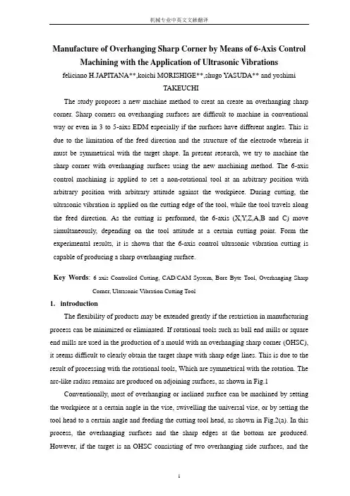
Manufacture of Overhanging Sharp Corner by Means of 6-Axis Control Machining with the Application of Ultrasonic Vibrations feliciano H.JAPITANA**,koichi MORISHIGE**,shugo YASUDA** and yoshimiTAKEUCHIThe study proposes a new machine method to creat an create an overhanging sharp corner. Sharp corners on overhanging surfaces are difficult to machine in conventional way or even in 3 to 5-aixs EDM especially if the surfaces have different angles. This is due to the limitation of the feed direction and the structure of the electrode wherein it must be symmetrical with the target shape. In present research, we try to machine the sharp corner with overhanging surfaces using the new machining method. The 6-axis control machining is applied to set a non-rotational tool at an arbitrary position with arbitrary position with arbitrary attitude against the workpiece. During cutting, the ultrasonic vibration is applied on the cutting edge of the tool, while the tool travels along the feed direction. As the cutting is performed, the 6-axis (X,Y,Z,A,B and C) move simultaneously, depending on the tool attitude at a certain cutting point. Form the experimental results, it is shown that the 6-axis control ultrasonic vibration cutting is capable of producing a sharp overhanging surface.Key Words: 6-axis Controlled Cutting, CAD/CAM System, Bore Byte Tool, Overhanging Sharp Corner, Ultrasonic Vibration Cutting Tool1.introductionThe flexibility of products may be extended greatly if the restriction in manufacturing process can be minimized or eliminated. If rotational tools such as ball end mills or square end mills are used in the production of a mould with an overhanging sharp corner (OHSC), it seems difficult to clearly obtain the target shape with sharp edge lines. This is due to the result of processing with the rotational tools, Which are symmetrical with the rotation. The arc-like radius remains are produced on adjoining surfaces, as shown in Fig.1 Conventionally, most of overhanging or inclined surface can be machined by setting the workpiece at a certain angle in the vise, swivelling the universal vise, or by setting the tool head to a certain angle and feeding the cutting tool head, as shown in Fig.2(a). In this process, the overhanging surfaces and the sharp edges at the bottom are produced. However, if the target is an OHSC consisting of two overhanging side surfaces, and theinclination angle of surface is not uniform, the processing of the target shape is difficult to achieve since the cutting direction in the process is fixed and limited only to linear cutting. Thus ,it needs a lot of jigs and fixtures to hold a workpiece ,to position correctly with respect to a machine tool and to support it during machining.Fig.1 5-axis control machining using rotational toolFig.2 method of producing sharp corner with overhanging surfacesThe other possible method to produce such a shape is multi-axis Electric Discharge Machining (EDM), as shown in Fig.2(b).However, even using this method ,it is difficult or impossible to produce an OHSC with different angle .It needs 6 degrees of freedom to fully execute the machining of the required shape.In the previous researches, ultrasonic vibration (USV) was applied in turning of ductile material and milling of glassfiber-reinforced plastic. The cutting force with USV is considerably reduced. However , in the former process ,the workpiece is rotated or moves to towards the cutting tool, and in the latter, machining is limited only to 2 or 3 axis control one. In the other field of research, multi-axis control machine tool is used to complete a machining in one setup, which leads to the production of workpiece with high accuracy and quality and to the reduction in machining time.In this study, 6-axis control cutting using a non-rotational cutting tool with the application of ultrasonic vibration (USV) is used, as shown in Fig.2(c).It is applied to scrutinize the validity of the method in the fabrication of OHSC, The C-axis rotates the non-rotational tool simultaneously together with X,Y,Z,A or B axis during machining .The movement of the axes is based on the tool attitude and the cutting point generated by a developed CAM software. The CAM program generates a collision free tool path to assure the safety of the process. The 6-axis control machine tool provides easily the machining capability of OHSC, since 6degrees of freedom make the machining execute fully the required product shape. Also, with the application of USV, a bore byte tool is utilizded, considering its size and stiffness during machining operation since the cutting force is greatly reduced.2.Experimental procedureThe experiment steup is shown in Fig.3, wherein the workpiece is mounted on the table of the 6-axis control machining center. The bore byte tool is mounted in the USV tool using an adaptor. The USV tool is turn mounted on the main spindle of the 6-axis control machining center.2.1Multi-axis control machine tool and bore byte toolThe 6-axis control machining center used in the study is shown inFig.4. The machining center provides multi-axis CNC machine tools.The 6-axis control machine tool has 3 rotational axes A,B and C. It is constructed by adding the rotational function C on the main spindle of a 5-axis control machining center which has 2 rotational axes,namely;A, which is a rotary tilting table and B, which is the rotary index table. The, and that of rotational one A,B minimum unit for translation movement X,Y and Z is 1mand C is 0.36 arc second. In the case of cutting of OHSC, A axis is used for determination of side surface and the inclination angle of sharp corner ,B axis for workpiece rotation ,C axis for determination of cutting tool direction, X and Y axis for the determination of feed direction of feed direction while the depth of cut is determined by Z axis. Fig 5 shows the non-rotational cutting tool (bore byte tool) used in the study. It is made of tungsten carbide usually used here in 6-axis control cutting. The total length and diameter of the tool are70mm and 6mm respectively.2.2Ultrasonic vibration toolFif.6 is a commercially available USV tool (SB-150:Taga Electric Co). used in the study. The USV is applied on the cutting edge of the tool.In order to perform an efficient and effective vibration cutting, the vibration direction must be set parallel to the cutting direction. Since the vibration direction is not always parallel with the feed direction, the tool attitude of the bore byte tool is subjected to arrangement. As illustrated in fig.7(a), the tool axis vextor T and the tool direction vector D and modified by arranging the rolling and the inclination angle respectively. These are converted into modified tool axis vector T and modified tool direction vector D, as shown in fig.7(b). The transformation of the tool axis vector and the tool direction vector are carried out in cutter location (CL) conversion.2.3CAD/CAM systemThe configuration of 6-axis CAD/CAM system is shown in fig.8, where 3D-CAD data of the target shape is generated . The type of bore byte tool must be selected, based on the target shape. The main processor generates the collision free CL data on the bases of tool information and tool orientation as well as 3D-CAD data of the target shape.The post processor converts CL data generated by the main processor into 6-axis control NC data suitable for the coordinate system of the machining center with reference to the structure information of the machining center, setting information, cutting condition and vibration condition. In addition, so-called linearization operation is dine in order to keep the feed rate to the machining center structure constant and to minimize the tool path deviation. It leads to assure the smoothness of the product surface especially in dealing with curve surfaces.Before converting CL data into NC data, CL data must be firstly checked for collision to assure the safety of the machining process .If the collision is detected in this stage, the modification of CL data is carried out, using the main processor.3.Manufacture of Sharp Corner with Overhanging Surface3.1Determination of tool attitudeIn order to expresshe entire tool attitude for 9-axis control ultrasonic vibration cutting, the tool attitude of the bore byte tool, as shown in Fig.9, is appointed by the coordinates P for cutting point, the tool axis vector T and the tool direction vector D. These PTD coordinates are converted to NC data, and are in turn used in machining operation. In6-axis control cutting with application of ultrasonic vibration, the movement and the attitude of the tool must be determined in consideration of the vibration direction. Since the cutting direction changes rapidly, the tool attitude changes a lot to keep the tool angle constant to the surface shape.3.2Generation of tool pathThe tool path generating method for OHSC can be described as follows; the OHSC is composed with two ridgelines, as illustrated in Fig.10. The intersecting line is called as a bottom ridgeline and the cross section line is called as a side ridgeline .Finishing the side ridgeline as well as the bottom ridgeline is required to make a sharp corner.3.2.1Generation of tool path for side surfaceThe surface that makes a side ridgeline is composed with left and right surfaces respectively. In producing a side ridgeline of the sharp corner, machining of left and right surfaces is necessary. The outline of the tool path generation method for side surfaces of the OHSC is described in Fig.11.The side to be machined and the tool feed direction must be selected at first, based on the type of bore byte tool and the target shape. The adjoining surfaces that make a side ridgeline, is expressed with parameters u and v. The fix curve , which is equal to parameter v, is generated on the side from the upper part of the surface to the bottom. The division number of surface is input to sequentially generate the number of cutting points. Each cutting point on a reference line are generated, using the value of parameter u, so that the distance between the cutting points may settle below in the specified value.Changing the tool attitude at every point of the cutter location ,the tool moves sequentially on each cutting point from the start point until the side ridgeline is formed. Although the cutting point is connected each other in order to acquire the tool path, it is difficult to process both adjoining sides by one direction due to the tool structure and the target product shape. In addition , the collision may take place between the tool and the workpiece. In this situation, the tool starts from the start point of the tool path to process the left side surface, and ends at the corner where the ridgeline is to be formed. Thus is repeated until it reaches to the bottom surface. The depth of cut is based in the division number of the total length of curve for curve surface. The same thing is done on the right side surface since there is still an arc-like remain at the corner part of the side surface. The procedure is almost the same as with the processing of the left side surface, however thecutting end point is the same with the end point of the left side processing, to form the clear ridgeline .Processing of the right side surfaces is also done using the left hand tool.The tool direction vector D during the tool path generation for side surfaces is rotated by 10degrees to make the vibration direction parallel to the feed direction vector F. The tool path is generated by connecting the cutting points in order from the starting point to the end point. The tool attitude during cutting is determined from the normal vector N and the tool feed direction vector F at the cutting point. The tool feed direction vector D and the tool axis vector T can be expressed as D=F*N and T=N respectively.3.2.2Generation of tool path for bottom surfaceFigure 12 describes that tool path generating method for bottom surface that makes the bottom surface that makes the bottom ridgeline of the OHSC. After generating the tool path for side surfaces, the tool path for bottom ridgeline is successively generated, where the tool is inclined to the bottom surfaces. There are two methods of generating a tool path for bottom surfaces; one is one-path method shown on the upper left part, and the other multi-path method shown in the upper right part of the figure. In one –path method ,the cutting tip of the tool directly makes contact with the location of the bottom ridgeline. In this operation, the tool inclination angle is necessary to fully remove the arc-like remains on the bottom surface and to form a clear ridgeline. During the tool path generation, the tool axis vector T is inclined, based on the calculated inclination angle against the bottom surface and the clearance angle of the cutting tool, which is 5 degrees.The method of determining the cutting start point as well as the cutting end point is the same as that of generating a tool path for side ridgeline.In multi-path method, the pitch from the bottom surface is expressed by use of parameters u and v. The generation range of a cutting reference line is determined from the shortest distance between the arc-like remains after rouging and the reference line of thebottom ridgeline. Cutting points is generated on the basis of parameter v in each reference line. The systems determines the tool attitude during cutting from the tool axis vector N at the bottom surface and the tool feed vector F at cutting point along a cutting reference line. The tool axis vector T and the tool direction vector D can be express as T=N and D=N*F respectively. The cutting start point is assumed near the arc-like radius remains and it ends at the last point of the generated cutting point in the reference line. Moving the tool along each neighboring cutting point can make the tool path.4.Experimental Results4.1Effect on cutting forceThe cutting force was measured by use of piezoelectric dynamometer (9257B,Kistler Co,Ltd), thus averaging the measured cutting force and processing it in the root mean square(rms) manner.table1 measured cutting forceMachining was conducted both with USV and without USV. The cutting conditions used are as follows: feed speed of 400mm/min and different depth of cut of 0.1,0.2,and 0.3mm respectively. The vibration conditions are in the following; frequency of 19kHz,and rolling angle of 10 degrees. The acquired result is shown in amplitude of 36mTable1. It can be seen that the cutting force in cutting with USV is much smaller as compared to cutting without USV. Since the cutting force was greatly reduced, the stiffness of the tool can be maintained all throughout the process.4.2Machining of OHSCThe cutting experiment was also made in order to scrutinize the validity of the new machining method. The workpiece size used for the experiment is 100×100×20 mm and the material is an aluminimu alloy(JIS A5052), which is also commonly used for low cost mould with low molding pressurre such as blow moulding, vacuum forming, rubbermoulding,etc.Two types of OHSC model were tired in the experiment, one is OHSC with plane surface and the other is OHSC with curve surface. The side surfaces consist of different inclination angle. The inclination angle o the surface at the cutting start point is not the same as the inclination angle at the cutting end point. In this condition, the inclination angle is not uniform all thoughout.Shown in Fig.13(a) is the machining model for OHSC with plane surfaces, rugh cutting must be at firdt done in order to perform an effcient cutting by 5-axis control machining, using the rotational ball end mill with a radius of 3mm and 1.5mm respectively. Machining is carried out until the target product shape is almost obtained. Since the target sharp corner is not clearly obtained due to the arc-like remains, as shown in Fig .13(b), finishing will be performed, using the 6-axis control cutting with the application of theUSV. with plane surface. Inthis process ,the left side or right side surface is firstly machined, depending on the choice.Let us assume that the left side surface is machined. The cutting and vibration conditions listed in Table 2 were used in machining on the basis of NC instructions generated by the developed CAM program. After machining the side surface, the bottom surfaces is machined in the next step, using the one path method. The cutting conditions listed in Table 2 were also used except for the inclinations angle of 9 degrees and the depth of cut of about 1.5mm. The depths of cut were based on the arc-like remains of the ball end mill used during roughing.Machining of the left side surfaces is done, using the right hang tool.After finishing the machining of the left side surface, the right side is processed in the next step under almost the same conditions as the processing of the left side except that the tool used is a left hand too. Shown in Fig.13(d) is the result of machining experiment.The machining model for OHSC with curve surfaces is shown in Fig.14(a). In machining OHSC with curve surface, roughing must also be performed, as shown in Fig.14(b). The sequence of operation from roughing to finishing is almost the same as described previously. However, so-called linearization operation is required to make the product surface smooth. To process the bottom surface that makes the ridgeline, the multi-path method was emplyed since the method is suitable in curved surfaces. Table 2 lists the cutting and vibration conditions used in the process. Also, shown in Fig.14(c) and Fig.14(d) are the actual machining and the product after finishing process respectively. The total machining time with this experiment is 112 minutes including rough cutting time. Only one machine was used as well as one steup of the workpiece in the entire process.The cutting effciency has been drastically improved due to the increase of cutting speed by applying of ultrasonic vibration since the normal cutting speed of non rotational cutting tools is equal to the feed rate.ConclusionThe experimental results show that the usage of bore byte tool is maximized and that the tool stiffness is enough to carry out machining due to the significant reduction of cutting force by applying the ultrasonic vibrations. It is found that only one machine can cope with machining of the product from roughing to fingshing , which leads to the potential of cost saving since the extra process like set-up from one machine to another can be eliminated. As a result, the validity of the developed CAM to machine OHSCs with plane and curve surface is experimentally confirmed throughout the study.AcknowledgementThe authors would like to express their sincere appreciation to Mr.Crisanto de laCruz(MIRDC-DOST) and Mr.Tohru Ishida (The University of Elector-Communications) for their valuable support and information.A part of the study is funded by the grant in aid for Scientific Research of the Ministry of Education (B12450057).references(1)Cecil, J A Clamping Design Approach for Automated Fixture Design, The InternationalJournal of Advanced Manufacturing Technology, V ol.18, No.11(2001),pp.790-793. (2)Moriwaki, T, Shanmoto ,E. and Inoue, K,Ultrapresicion Ductile Cutting of Glass byApplying Ultrasonic Vibration, Annals of the CIRP,V ol.41, No.1(1992),pp.141-144. (3)Takeyama, H. and Iijima, N, Machinability of Glassfiber Reinforced Plastics andApplication of Ultrasonic Machining, Annals of the CIRP, V ol.37, No.1(1998),pp.93-96.(4)Shamoto, E. and Moriwaki, T, Study on Elliptical Vibration Cutting, Annals of theCIRP, V ol.43,No.1(1994),pp.35-38.(5)Moriwaki ,T. and Shamoto, E,Ultrasonic Elliptical Vibration Cutting ,Annals of theCIRP, V ol.44,No.1 (1995),pp.31-34.(6)Takeuchi, Y. and Suzuki, H. Efficient and Accurate Manufacturing by means ofMulti-Axis Control Machine Tools, Proceedings of the Japan-USA Symposium on Flexible Automation, ASME and ISCIEJ, Boston, Massachusetts, July7-10,1996,V ol.1,pp.343-347.(7)Radzevich, S.P. and Goodman, E .D, Efficiency of Multi-Axis NC Machining ofSculptured Surface, Proceedings of the International Conference on Sculptured Surface machining, Nov.9-11,1998,pp42-56.(8)Morishige, K, Kase,K and Takeuchi, Y, Collision-free Tool path Generation GenerationUsing 2-Dimensional C-Space for 5-Axis Control Machining, The International Journal of Advanced Manufacturing Technology, V ol.13, No.6(1997),pp.393-400.(9)Morishige, K, Kase,K and Takeuchi, Y, six Axis Control Character Line FinishingUsing Ultrasonic Vibrational Cutting Tool, 10th International Conference on Precision Engineering (ICPE), Yokohama, Japan, July 18-20,2001,pp.249-2563.。
英文原文Study of Inherent Safety Mine hoist based on modern designmethodsYang Lijie 1, Meng Xiangyun2,Wang Guimei1,Niu Qingna11 Hebei University of Engineering, Handan, Hebei, 056038, ChinaYanglijie255@2 China Telecom Handan Company, Handan, Hebei, 056038, China Abstract—As a modern security design, Inherent Safety means that equipment and facilities is able to contain the inherent fundamental features to prevent accidents. Mine hoist is the most important equipment in the coal production. How to achieve safe, reliable, efficient production has been the focus study at home and abroad. Inherent safety is reflected in hoist design, primarily through the design measures to improve the operation of hoist safety and reliability. In this paper, Inherent Safety theory is applied in the design of mine hoist, to proposed the design method by using the software of PRO/E PLC, Labview etc..Keywords-Mine hoist; Inherent Safety; PRO/E; PLC; LabviewI. INTRODUCTIONIn coal production, mine hoist is the equipment to carry coal, gangue, materials, workers and equipments along the rockshaft, the only way linked underground and aboveground, known as mine throat. Mine hoist is a large-scale reciprocating machinery which has the feature of own big inertia, load changes, running speed, and wide range et al.. The advantages and disadvantages of its operating performance, not only directly affect the normal production and coal production efficiency, but also relate to equipment and personal safety. In recent years, mine hoist failures and accidents have happened at home and abroad which have paid a heavy price to coal companies. Therefore, the production technology and safety of mine hoist are higher, and its mechanical manufacturing technology and electrical control technology has been an important research area to the international machine building industry and the electric control industry.Inherent Safety means that equipment and facilities is able to contain the inherent fundamental features to prevent accidents. Inherent Safety lies in design, through continuous improvement, to prevent accidents due to the equipment itself failures. Inherent safety is reflected in hoist design, primarily through the design measures to improve the operation of hoist safety and reliability. In this paper, Inherent Safety theory is applied in the design of mine hoist, to proposed the inherent safety design method by use the software of PRO/E PLC, Labview etc..II. INHERENT SAFETY THEORYThe term of inherent safety originates the development of world space technology in the 1950s. The concept is widely accepted closely linked with scientific technological progress and human understanding of safety culture. The concept of inherent safety produced after the World War II which became major safety concept in many industrialized countries since the mid 20th century.Inherent safety design as the basic method of hazard control, by selecting safe materials, process routes, mechanical equipment, devices, to eliminate or control hazards source rather than relying on "additional" security measures or management measures to control them. As inherent safety design, firstly analyze and identify hazards that may occur in system, and then choose the best methods to eliminate, control hazards, which reflected in project design.Ⅲ. THE DESIGN OF INHERENT SAFETY MINE HOISTMine hoist mainly includs the working device, control system, transmission system and drag, protection systems and other components. To the inherent safety mine hoist design, mainly the mechanical system, control system and monitor system is the major part to considered.A.In-depth investigations to find malfunctionThe concept of inherent safety is required safety all the time in the product design process. That is, the equipment has little malfunction as much as possible during the operation and has long normal operation cycle length. How can design inherent safety equipment, the most important thing is understanding enough to the equipment, especially in work. After in-depth research, fully understanding the situation, try the best to reduce or eliminate the fault in the design. After in-depth understanding of research, design product.B. Mechanical SystemThe traditional method of product has long design cycle, high costs. However, the virtual prototype technology has the advantage in saving the design cost, shortening the design circle, by using the method of modeling, simulation first and then builds the physical prototype. Therefore, the virtual design is the developing trends of mechanical design. In mechanical system design, the application of virtual prototype is used to design mine hoist, not only speeded up the design process, also simulated a variety of conditions to the virtual prototype to discover design faults, to improve the design, to improve mine hoist performance.Mine hoist mechanical system is composed of spindle, roller, reducer, motor, brakes and other components. In its design, virtual design software PRO / E is applied to establish hoist prototype, application of simulation software ADAMS is used to simulate and optimize the design. Specific process shown in Figure 1:Figure 1. Mechanical system designC. Control system designMine hoist control system includes start, run, brake, etc., the requirements in control system are:In normal hoist operation, participation in hoist speed control, brake the hoist when reaching the destination, known as the service braking;In case of emergency, can quickly slow down as required, brake hoist, to prevent the expansion of the accident, that is the safety braking; Participate in the hoist speed control when decelerati; To double-roller hoist, should brake the moving roller and fix roller respectively when regulating rope length, replacement level and changing rope, so that, moving roller would not move when spindle rotates with the fixed roller.Most of mine hoists in China (more than 70%) use the traditional electric control system (tkd-a as the representative). Tkd control system is composed of relay logic circuits, large air contactors, tachometer generator etc., which is a touch control system. After years of development, tkd-a series of electric control system has formed its own characteristics, but its shortcomings are obvious. Its electrical circuit is too complicated, multi-line, causing hoist parking and accidents occurred due to electrical fault. With the computer and digital technology, to form a digital hoist control systemof PLC has become possible. PLC control system has high control precision, parameter stability, simple hardware structure, self-diagnostic capability and communication networking function.Mine hoist control system based on PLC technology structure shown in Figure 2, mainly including the following components: the main plc control circuits, hoist route detection and display circuits, speed detection, and signal circuits. The PLC of the main control circuits uses Mitsubishi FX2N series in Japan which more domestic applications.Figure 2 PLC electric control systemD. Monitoring system designTo ensure safe operation of the hoist, except for selecting the reasonable operation design parameters, the use of advanced control system, should also monitor the technological parameters on regular, conscientiously do performance test work to master the hoist performance, discover the defects in time, eliminate hidden danger,avoid unnecessary losses. In addition, the hoist operation state can be improved to work in the best conditions based on test data. Therefore, the hoist could work safely, reliably, have high efficiency, and extend its work life.Virtual instrument technology is computer-based instrumentation and measurement technology, is loaded some software and hardware on the computer with similar appearance and performance of the actual independent instrument. The user operating the computer, like manipulating a especially conventional electronic devices designed theirs. The essence of virtual instrument technology is that hardware softwarized technology, take full advantage of the latest computer technology to implement and expand the functions of traditional instruments.LabVIEW (laboratory virtual instrument engineering workbench) is a graphical programming and development environment, also known as "G" language. It is widely used by industry, academia and research laboratories, accepted as the standard data acquisition and instrument control software. LabVIEW not only provides and complies with all the functions of hardware and data acquisition cards communications of GPIB, VXI, RS-232 and RS-485 protocol, and built-in library functions support for TCP / IP, ActiveX and other software standards. The software for scientists and engineers is a programming language, it provides a simple, intuitive graphical programming mode, saves a lot of development time, has complete function, best embodied style of virtual instrument.In response to these circumstances, developed a mine hoist Integrate Performance Monitoring System based on virtual instrument LabVIEW-based. Show in Figure 3. With signal conditioning and data acquisition card to receive signals from sensors, then sent the received signal to the virtual instrument software platform, enables the following features:(1)show speed, acceleration, braking time, displacement, oil pressure, delay time and other relevant parameters in digital, and display speed, acceleration, traction, displacement and hydraulic curves.(2)Dynamically monitor the hydraulic oil pressure and oil pump running station, based on these parameters to avoid important braking system failure.(3)Test brake air travel time, relay delay time and other time parameters.(4)inquiry to the measured curve and hoist parameters; print a test report.Figure 3. Diagram of test systemThe monitoring system has characteristics such as compact, light weight, high precision, testing convenient and flexible, feature-rich software etc.. the system can not only display automatically test results, but also finish multiple functions, for example , data transmission, analysis, processing, storage and report printing. The system is high precision, can easily monitor the hoist operation state, to ensure the reliability of hoist operation.Ⅳ. CONCLUSIONSIn this paper, used virtual design software to design the hoist mechanical system, PLC to design control system, applied virtual instrument software-LABVIEW to design monitor system. Therefore, the mine hoist designed has good mechanical properties and safe operation, monitoring easy.REFERENCES[1] Weng qishu. The inherent safety and checks of cabin[J]. navigationTechnology 2006 (3):50-52. (in Chinese)[2] Li jangbo. Study of Test System of Composite Characteristic of Devices Based onVirtual instrument[D]. A Dissertation Submitted to Hebei University ofEngineering For the Academic Degree of Master of Engineering, 2007. (inChinese)[3] Wang chengqin, Li wei , Meng baoxing et al... Random vibration testing system ofhoisting gear based on virtual instrument. Coal mine machinery, 2008(4) :118-120.(in Chinese)[4] Chen baozhi Wu min. concept and practices of inherent safety[J]. Journal ofSafety Science and Technology,2008(6):79-83. (in Chinese)[5] Xu chenyi, Wu yongdong, Huanghe et al.. A PLC-based mine hoist control systemdesign [J]. LC&FA, 2008(10):52-56 (in Chinese)中文译文基于现代设计方法的矿井提升机内在安全性的研究Yang Lijie 1, Meng Xiangyun2,Wang Guimei1,Niu Qingna11河北工程大学,河北邯郸,056038,中国Yanglijie255@2中国电信邯郸分公司,河北邯郸,056038,中国摘要:作为一个现代的安全设计,内在的安全性意味着设备和设施能够包含防止事故发生的固有基本特征。

Failure Analysis,Dimensional Determination And Analysis,Applications Of Cams And MouldINTRODUCTIONMechanical design is the application of science and technology to devise new or improved products for the purpose of satisfying human needs. It is a vast field of eng ineering technology which not only concerns itself with the original conception of the product in terms of its size, shape and construction details, but also considers the va rious factors involved in the manufacture, marketing and use of the product.People wh o perform the various functions of mechanical design are typically called designers, or design engineers. Mechanical design is basically a creative activity. However, in addit ion to being innovative, a design engineer must also have a solid background in the a reas of mechanical drawing, kinematics, dynamics, materials engineering, strength of m aterials and manufacturing processes.As stated previously, the purpose of mechanical design is to produce a product which will serve a need for man. Inventions, discoveries and scientific knowledge by themselves do not necessarily benefit people; only if they are incorporated into a desi gned product will a benefit be derived. It should be recognized, therefore, that a hum an need must be identified before a particular product is designed.It is absolutely essential that a design engineer know how and why parts fail so that reliable machines that require minimum maintenance can be designed.Sometimes a failure can be serious,such as when a tire blows out on an automobile traveling at high speed.On the other hand,a failure may be no more than a nuisance.An exam ple is the loosening of the radiator hose in an automobile cooling system.The conseq uence of this latter failure is usually the loss of some radiator coolant,a condition th at is readily detected and corrected.The type of load a part absorbs is just as significant as the magnitude.Generally speaking,dynamic loads with direction reversals cause greater difficulty than static loa ds,and therefore,fatigue strength must be considered.Another concern is whether th e material is ductile or brittle.For example,brittle materials are considered to be una cceptable where fatigue is involved.Many people mistakingly interpret the word failure to mean the actual breaka ge o f a part.However,a design engineer must consider a broader understanding of what appreciable deformation occurs.A ductile material,however will deform a large amou nt prior to rupture.Excessive deformation,without fracture,may cause a machine to fail because the deformed part interferes with a moving second part.Therefore,a part fails(even if it has not physically broken)whenever it no longer fulfills its required fu nction.Sometimes failure may be due to abnormal friction or vibration between two mating parts.Failure also may be due to a phenomenon called creep,which is the plastic flow of a material under load at elevated temperatures.In addition,the actual s hape of a part may be responsible for failure.For example,stress concentrations due to sudden changes in contour must be taken into account.Evaluation of stress conside rations is especially important when there are dynamic loads with direction reversals a nd the material is not very ductile.In general,the design engineer must consider all possible modes of failure,whic h include the following.——Stress——Deformation——Wear——Corrosion——Vibration——Environmental damage——Loosening of fastening devicesThe part sizes and shapes selected also must take into account many dimensional factors that produce external load effects,such as geometric discontinuities,residual stresses due to forming of desired contours,and the application of interference fit join ts.Cams are among the most versatile mechanisms available.A cam is a simple two -member device.The input member is the cam itself,while the output member is cal led the follower.Through the use of cams,a simple input motion can be modified i nto almost any conceivable output motion that is desired.Some of the common applic ations of cams are——Camshaft and distributor shaft of automotive engine——Production machine tools——Automatic record players——Printing machines——Automatic washing machines——Automatic dishwashersThe contour of high-speed cams (cam speed in excess of 1000 rpm) must be det ermined mathematically.However,the vast majority of cams operate at low speeds(les s than 500 rpm) or medium-speed cams can be determined graphically using a large-s cale layout.In general,the greater the cam speed and output load,the greater must be the precision with which the cam contour is machined.DESIGN PROPERTIES OF MATERIALSThe following design properties of materials are defined as they relate to the tens ile test.Figure 2.7Static Strength.The strength of a part is the maximum stress that the part can sust ain without losing its ability to perform its required function.Thus the static strength may be considered to be approximately equal to the proportional limit,since no plasti c deformation takes place and no damage theoretically is done to the material.Stiffness.Stiffness is the deformation-resisting property of a material.The slope of t he modulus line and,hence,the modulus of elasticity are measures of the stiffness of a material.Resilience.Resilience is the property of a material that permits it to absorb energy without permanent deformation.The amount of energy absorbed is represented by the area underneath the stress-strain diagram within the elastic region.Toughness.Resilience and toughness are similar properties.However,toughness is t he ability to absorb energy without rupture.Thus toughness is represented by the total area underneath the stress-strain diagram,as depicted in Figure 2.8b.Obviously,t he toughness and resilience of brittle materials are very low and are approximately eq ual.Brittleness.A brittle material is one that ruptures before any appreciable plastic defo rmation takes place.Brittle materials are generally considered undesirable for machinecomponents because they are unable to yield locally at locations of high stress becaus e of geometric stress raisers such as shoulders,holes,notches,or keyways.Ductility.A ductility material exhibits a large amount of plastic deformation prior to rupture.Ductility is measured by the percent of area and percent elongation of a part loaded to rupture.A 5%elongation at rupture is considered to be the dividing line bet ween ductile and brittle materials.Malleability.Malleability is essentially a measure of the compressive ductility of a material and,as such,is an important characteristic of metals that are to be rolled int o sheets.Figure 2.8Hardness.The hardness of a material is its ability to resist indentation or scratchin g.Generally speaking,the harder a material,the more brittle it is and,hence,the l ess resilient.Also,the ultimate strength of a material is roughly proportional to its ha rdness.Machinability.Machinability is a measure of the relative ease with which a material can be machined.In general,the harder the material,the more difficult it is to mach ine.COMPRESSION AND SHEAR STATIC STRENGTHIn addition to the tensile tests,there are other types of static load testing that provide valuable information.Compression Testing.Most ductile materials have approximately the same properties in compression as in tension.The ultimate strength,however,can not be evaluated f or compression.As a ductile specimen flows plastically in compression,the material bulges out,but there is no physical rupture as is the case in tension.Therefore,a d uctile material fails in compression as a result of deformation,not stress.Shear Testing.Shafts,bolts,rivets,and welds are located in such a way that shea r stresses are produced.A plot of the tensile test.The ultimate shearing strength is d efined as the stress at which failure occurs.The ultimate strength in shear,however,does not equal the ultimate strength in tension.For example,in the case of steel,th e ultimate shear strength is approximately 75% of the ultimate strength in tension.Thi s difference must be taken into account when shear stresses are encountered in machi ne components.DYNAMIC LOADSAn applied force that does not vary in any manner is called a static or steady lo ad.It is also common practice to consider applied forces that seldom vary to be stati c loads.The force that is gradually applied during a tensile test is therefore a sta tic l oad.On the other hand,forces that vary frequently in magnitude and direction are cal led dynamic loads.Dynamic loads can be subdivided to the following three categories.Varying Load.With varying loads,the magnitude changes,but the direction does n ot.For example,the load may produce high and low tensile stresses but no compress ive stresses.Reversing Load.In this case,both the magnitude and direction change.These load reversals produce alternately varying tensile and compressive stresses that are commonl y referred to as stress reversals.Shock Load.This type of load is due to impact.One example is an elevator droppi ng on a nest of springs at the bottom of a chute.The resulting maximum spring forc e can be many times greater than the weight of the elevator,The same type of shock load occurs in automobile springs when a tire hits a bump or hole in the road.FATIGUE FAILURE-THE ENDURANCE LIMIT DIAGRAMThe test specimen in Figure 2.10a.,after a given number of stress reversals wil l experience a crack at the outer surface where the stress is greatest.The initial crack starts where the stress exceeds the strength of the grain on which it acts.This is us ually where there is a small surface defect,such as a material flaw or a tiny scratc h.As the number of cycles increases,the initial crack begins to propagate into a con tinuous series of cracks all around the periphery of the shaft.The conception of the i nitial crack is itself a stress concentration that accelerates the crack propagation pheno menon.Once the entire periphery becomes cracked,the cracks start to move toward t he center of the shaft.Finally,when the remaining solid inner area becomes small en ough,the stress exceeds the ultimate strength and the shaft suddenly breaks.Inspectio n of the break reveals a very interesting pattern,as shown in Figure 2.13.The outer annular area is relatively smooth because mating cracked surfaces had rubbed againsteach other.However,the center portion is rough,indicating a sudden rupture similar to that experienced with the fracture of brittle materials.This brings out an interesting fact.When actual machine parts fail as a result of static loads,they normally deform appreciably because of the ductility of the material.Figure 2.13Thus many static failures can be avoided by making frequent visual observations and replacing all deformed parts.However,fatigue failures give to warning.Fatigue f ail mated that over 90% of broken automobile parts have failed through fatigue.The fatigue strength of a material is its ability to resist the propagation of cracks under stress reversals.Endurance limit is a parameter used to measure the fatigue str ength of a material.By definition,the endurance limit is the stress value below whic h an infinite number of cycles will not cause failure.Let us return our attention to the fatigue testing machine in Figure 2.9.The test is run as follows:A small weight is inserted and the motor is turned on.At failure of the test specimen,the counter registers the number of cycles N,and the correspon ding maximum bending stress is calculated from Equation 2.5.The broken specimen i s then replaced by an identical one,and an additional weight is inserted to increase t he load.A new value of stress is calculated,and the procedure is repeated until failu re requires only one complete cycle.A plot is then made of stress versus number of cycles to failure.Figure 2.14a shows the plot,which is called the endurance limit or S-N curve.Since it would take forever to achieve an infinite number of cycles,1 mi llion cycles is used as a reference.Hence the endurance limit can be found from Fig ure 2.14a by noting that it is the stress level below which the material can sustain 1 million cycles without failure.The relationship depicted in Figure 2.14 is typical for steel,because the curve be comes horizontal as N approaches a very large number.Thus the endurance limit equ als the stress level where the curve approaches a horizontal tangent.Owing to the lar ge number of cycles involved,N is usually plotted on a logarithmic scale,as shown in Figure 2.14b.When this is done,the endurance limit value can be readily detected by the horizontal straight line.For steel,the endurance limit equals approximately 5 0% of the ultimate strength.However,if the surface finish is not of polished equality,the value of the endurance limit will be lower.For example,for steel parts with a machined surface finish of 63 microinches ( μin.),the percentage drops to about 4 0%.For rough surfaces (300μin.or greater),the percentage may be as low as 25%.The most common type of fatigue is that due to bending.The next most frequent is torsion failure,whereas fatigue due to axial loads occurs very seldom.Spring mat erials are usually tested by applying variable shear stresses that alternate from zero to a maximum value,simulating the actual stress patterns.In the case of some nonferrous metals,the fatigue curve does not level off as th e number of cycles becomes very large.This continuing toward zero stress means that a large number of stress reversals will cause failure regardless of how small the valu e of stress is.Such a material is said to have no endurance limit.For most nonferro us metals having an endurance limit,the value is about 25% of the ultimate strength.EFFECTS OF TEMPERATURE ON YIELD STRENGTH AND MODULUS OF E LASTICITYGenerally speaking,when stating that a material possesses specified values of pro perties such as modulus of elasticity and yield strength,it is implied that these values exist at room temperature.At low or elevated temperatures,the properties of material s may be drastically different.For example,many metals are more brittle at low temp eratures.In addition,the modulus of elasticity and yield strength deteriorate as the te mperature increases.Figure 2.23 shows that the yield strength for mild steel is reduce d by about 70% in going from room temperature to 1000o F.Figure 2.24 shows the reduction in the modulus of elasticity E for mild steel as the temperature increases.As can be seen from the graph,a 30% reduction in modul us of elasticity occurs in going from room temperature to 1000o F.In this figure,we also can see that a part loaded below the proportional limit at room temperature can be permanently deformed under the same load at elevated temperatures.Figure 2.24CREEP: A PLASTIC PHENOMENONTemperature effects bring us to a phenomenon called creep,which is the increasi ng plastic deformation of a part under constant load as a function of time.Creep also occurs at room temperature,but the process is so slow that it rarely becomes signifi cant during the expected life of the temperature is raised to 300o C or more,the incre asing plastic deformation can become significant within a relatively short period of ti me.The creep strength of a material is its ability to resist creep,and creep strength data can be obtained by conducting long-time creep tests simulating actual part operati ng conditions.During the test,the plastic strain is monitored for given material at sp ecified temperatures.Since creep is a plastic deformation phenomenon,the dimensions of a part experi encing creep are permanently altered.Thus,if a part operates with tight clearances,t he design engineer must accurately predict the amount of creep that will occur during the life of the machine.Otherwise,problems such binding or interference can occur.Creep also can be a problem in the case where bolts are used to clamp tow part s together at elevated temperatures.The bolts,under tension,will creep as a function of time.Since the deformation is plastic,loss of clamping force will result in an un desirable loosening of the bolted joint.The extent of this particular phenomenon,call ed relaxation,can be determined by running appropriate creep strength tests.Figure 2.25 shows typical creep curves for three samples of a mild steel part und er a constant tensile load.Notice that for the high-temperature case the creep tends to accelerate until the part fails.The time line in the graph (the x-axis) may represent a period of 10 years,the anticipated life of the product.Figure 2.25The machine designer must understand the purpose of the static tensile strength te st.This test determines a number of mechanical properties of metals that are used in design equations.Such terms as modulus of elasticity,proportional limit,yield strengt h,ultimate strength,resilience,and ductility define properties that can be determined from the tensile test.Dynamic loads are those which vary in magnitude and direction and may require an investiga tion of the machine part’s resistance to failure.Stress reversals may requi re that the allowable design stress be based on the endurance limit of the material rat her than on the yield strength or ultimate strength.Stress concentration occurs at locations where a machine part changes size,such as a hole in a flat plate or a sudden change in width of a flat plate or a groove or f illet on a circular shaft.Note that for the case of a hole in a flat or bar,the value of the maximum stress becomes much larger in relation to the average stress as the si ze of the hole decreases.Methods of reducing the effect of stress concentration usuall y involve making the shape change more gradual.Machine parts are designed to operate at some allowable stress below the yield st rength or ultimate strength.This approach is used to take care of such unknown facto rs as material property variations and residual stresses produced during manufacture an d the fact that the equations used may be approximate rather that exact.The factor of safety is applied to the yield strength or the ultimate strength to determine the allow able stress.Temperature can affect the mechanical properties of metals.Increases in temperat ure may cause a metal to expand and creep and may reduce its yield strength and its modulus of elasticity.If most metals are not allowed to expand or contract with a c hange in temperature,then stresses are set up that may be added to the stresses from the load.This phenomenon is useful in assembling parts by means of interference fit s.A hub or ring has an inside diameter slightly smaller than the mating shaft or pos t.The hub is then heated so that it expands enough to slip over the shaft.When it cools,it exerts a pressure on the shaft resulting in a strong frictional force that pre ve nts loosening.TYPES OF CAM CONFIGURATIONSPlate Cams.This type of cam is the most popular type because it is easy to design and manufacture.Figure 6.1 shows a plate cam.Notice that the follower moves per pendicular to the axis of rotation of the camshaft.All cams operate on the principle t hat no two objects can occupy the same space at the same time.Thus,as the cam r otates ( in this case,counterclockwise ),the follower must either move upward or bi nd inside the guide.We will focus our attention on the prevention of binding and att ainment of the desired output follower motion.The spring is required to maintain cont act between the roller of the follower and the cam contour when the follower is movi ng downward.The roller is used to reduce friction and hence wear at the contact surf ace.For each revolution of the cam,the follower moves through two strokes-bottom dead center to top dead center (BDC to TDC) and TDC to BDC.Figure 6.2 illustrates a plate cam with a pointed follower.Complex motions can be pr oduced with this type of follower because the point can follow precisely any suddenchanges in cam contour.However,this design is limited to applications in which the loads are very light;otherwise the contact point of both members will wear premature ly,with subsequent failure.Two additional variations of the plate cam are the pivoted follower and the offset sliding follower,which are illustrated in Figure 6.3.A pivoted follower is used when rotary output motion is desired.Referring to the offset follower,note that the amount of offset used depends on such parameters as pressure angle and cam profile flatness,which will be covered later.A follower that has no offset is called an in-line follower.Figure 6.3Translation Cams.Figure 6.4 depicts a translation cam.The follower slides up and down as the cam translates motion in the horizontal direction.Note that a pivoted fol lower can be used as well as a sliding-type follower.This type of action is used in c ertain production machines in which the pattern of the product is used as the cam.A variation on this design would be a three-dimensional cam that rotates as well as tran slates.For example,a hand-constructed rifle stock is placed in a special lathe.This s tock is the pattern,and it performs the function of a cam.As it rotates and translate s,the follower controls a tool bit that machines the production stock from a block of wood.Figure 6.4Positive-Motion Cams.In the foregoing cam designs,the contact between the cam a nd the follower is ensured by the action of the spring forces during the return strok e.However,in high-speed cams,the spring force required to maintain contact may b ecome excessive when added to the dynamic forces generated as a result of accelerati ons.This situation can result in unacceptably large stress at the contact surface,whic h in turn can result in premature wear.Positive-motion cams require no spring becaus e the follower is forced to contact the cam in two directions.There are four basic ty pes of positive-motion cams: the cylindrical cam,the grooved-plate cam ( also called a face cam ) ,the matched-plate cam,and the scotch yoke cam.Cylindrical Cam.The cylindrical cam shown in Figure 6.5 produces reciprocating foll ower motion,whereas the one shown in Figure 6.6 illustrates the application of a piv oted follower.The cam groove can be designed such that several camshaft revolutions are required to produce one complete follower cycle.Grooved-plate Cam.In Figure 6.8 we see a matched-plate cam with a pivoted follow er,although the design also can be used with a translation follower.Cams E and F r otate together about the camshaft B.Cam E is always in contact with roller C,while cam F maintains contact with roller D.Rollers C and D are mounted on a bell-cran k lever,which is the follower oscillating about point A.Cam E is designed to provi de th e desired motion of roller C,while cam F provides the desired motion of roller D.Scotch Yoke Cam.This type of cam,which is depicted in Figure 6.9,consists of a circular cam mounted eccentrically on its camshaft.The stroke of the follower equals two times the eccentricity e of the cam.This cam produces simple harmonic motion with no dwell times.Refer to Section 6.8 for further discussion.CAM TERMINOLOGYBefore we become involved with the design of cams,it is desirable to know the various terms used to identify important cam design parameters.The following terms r efer to Figure 6.11.The descriptions will be more understandable if you visualize the cam as stationary and the follower as moving around the cam.Trace Point.The end point of a knife-edge follower or the center of the roller of a roller-type follower.Cam Contour.The actual shape of the cam.Base Circle.The smallest circle that can be drawn tangent to the cam contour.Its ce nter is also the center of the camshaft.The smallest radial size of the cam stars at th e base circle.Pitch Curve.The path of the trace point,assuming the cam is stationary and the foll ower rotates about the cam.Prime Circle.The smallest circle that can be drawn tangent to the pitch curve.Its ce nter is also the center of the camshaft.Pressure Angle.The angle between the direction of motion of the follower and the no rmal to the pitch curve at the point where the center of the roller lies.Cam Profile.Same as cam contour.BDC.Bottom Dead Center,the position of the follower at its closest point to the ca m hub.Stroke.The displacement of the follower in its travel between BDC and TDC.Rise.The displacement of the follower as it travels from BDC to TDC.Return.The displacement of the follower as it travels from TDC or BDC.Ewell.The action of the follower when it remains at a constant distance from the ca m hub while the cam turns.A clearer understanding of the significance of the pressure angle can be gained b y referring to Figure 6.12.Here F T is the total force acting on the roller.It must be normal to the surfaces at the contact point.Its direction is obviously not parallel to t he direction of motion of the follower.Instead,it is indicated by the angle α,the pr essure angle,measured from the line representing the direction of motion of the follo wer.Therefore,the force F T has a horizontal component F H and a vertical component F V.The vertical component is the one that drives the follower upward and,therefore,neglecting guide friction,equals the follower F lood.The horizontal component has no useful purpose but it is unavoidable.In fact,it attempts to bend the follower about it s guide.This can damage the follower or cause it to bind inside its guide.Obviously,we want the pressure angle to be as possible to minimize the side thrust F H.A practi cal rule of thumb is to design the cam contour so that the pressure angle does not ex ceed 30o.The pressure angle,in general,depends on the following four parameters:——Size of base circle——Amount of offset of follower——Size of roller——Flatness of cam contour ( which depends on follower stroke and type of follower motion used )Some of the preceding parameters cannot be changed without altering the cam requirements,such as space limitations.After we have learned how to design a cam,we will discuss the various methods available to reduce the pressure angle.General all-steel punching die’s punching accuracyAccuracy of panel punching part is display the press accuracy of the die exactly. But the accuracy of any punching parts’ linear dimension and positional accuracy al most depend on the blanking and blanking accuracy. So that the compound mould of compound punching accuracy, is typical-ness and representation in the majority.Analysis of the die’s accuracyFor the analysis of practicable inaccuracy during production of dies to inactivation, we could get the tendency when it is augmentation in most time. From this we coul d analyze the elements. When the new punch dies pt into production to the first cutte r grinding, the inaccuracy produced called initial error; if the die grinding more than t wenty times, until it’s discard, the inaccuracy called conventional error; and before the dies discard, the largest error of the last batch permit, called limiting error. at job sit e, the evidence to confirm life of sharpening is the higher of the blanking, punched h ole or punched parts. Because all finished parts had been blanked ,so it is especially for the compound dies. Therefore, the analysis of burr and measurement is especially important when do them as enterprise standardization or checked with <<the height of punching part>>.The initial error usually is the minimal through the whole life of die. Its magnit ude depend on the accuracy of manufacture, quality, measure of the punching part, thi ckness of panel, magnitude of gap and degree of homogeneity. The accuracy of manu facture depend on the manufacture process. For the 1 mm thicket compound punching part made in medium steel, the experimental result and productive practice all prove that the burr of dies which produced by spark cutting are higher 25%~~30% than pro duced by grinder ,NC or CNC. The reason is that not only the latter have more exact machining accuracy but also the value of roughness Ra is less one order than the fo rmer, it can be reached 0.025μm. Therefore, the die’s initial blanked accuracy depends on the accuracy of manufacture, quality and so on.The normal error of the punch die is the practicable error when the fist cutter gr inding and the last cutter grinding before the die produce the last qualified product. A s the increase of cutter grinding, caused the measure the nature wear of the dies are gradual increasing, the error of punching part increase also, so the parts are blew pro of. And the die will be unused. The hole on the part and inner because the measure of wear will be small and small gradually, and its outside form will be lager in the s ame reason. Therefore, the hole and inner form in the part will be made mould accor ding to one-way positive deviation or nearly equal to the limit max measure. In like manner, the punching part’s appearance will be made mould according to one-way ne。

MS Access MRP Manufacturing Resource PlanningSmall Business MRP - Small Business ERPMicrosoft Access Database ERP MRP ProgramERP / MRP Manufacturing Software ProgramPEDYN specializes in Small Business Manufacturing Operations, Engineering Management, and Document Control Software. See the all in one P2000 Enterprise Resource Planning (ERP / MRP) program that uses Microsoft Access as the program platform. The P2000 is a powerful Low Cost solution for your complete business operations, from design concept, project management and documentations control to purchasing, material control, manufacturing, and order entry. It's graphical design and drill down navigation make the P2000 very easy to learn and use. Since the program is completely written using Microsoft Access, it interfaces well with other products, and can be easily customized to fit your ever changing business requirements. The program can be used along with other ERP / MRP programs that your company may be using by activating only the modules that you require. The P2000 is expandable, flexible and provides the perfect low cost solutions for small to mid size engineering and manufacturing companies. Why spend a fortune on expensive complicated system programs that are not easily adaptable to your specific needs. Using Microsoft Access as a front-end operating system means that you havefull control and flexibility. Create new forms and reports as you need them. Expand your operating system anyway you choose.ERP software Categories and Features1.Manufacturing and Operations Modules:Manufacturing Software, Manufacturing Program, Operations Software, Operations Program, Manufacturing Solutions, Production Management Program, Production Control Management, Discrete Manufacturing, Production Planning, Material Requirement Planning (MRP), Manufacturing Resource Planning (MRP II), Enterprise Resource Planning, ERP Software, MIS, Stock Replenishment Systems, Production Workflow Management, Product Management, Supply Chain Management, SCM, Supply Management, Materials Management, Business Management, Planning and Scheduling Enterprise, Multi-User Manufacturing Control Software, Inventory Management, Inventory Control, Product Management, Stock Control software, Small Business Soluitions, Small Business MRP, Small Business ERP2.Engineering Modules:Engineering Management Software, Engineering Software, Engineering Program, Engineering Project Management Software Programs, Design Management Software Engineer Task Management, Engineering Task Management, Daily Task Management, Tasking,Engineering Change Notice, Engineering Change Request, Engineering Change Order, Engineering Change Orders, ECN, ECO, DCO, DCN, ECR, DCR, Engineering Operations, Engineering Project Planning and Scheduling, Online Task Management3.Documentation Modules:Documentation Control software, Document Control Management, Drawing Control, Configuration Control Management, Configuration Management Software, Configuration Control Software, Drafting Management, Document Change Order, Change Orders, BOM software, Bill Of Materials, Indented Multi Level, Reference Designators, Drafting Task Management,Draftsman,CAD, AUTOCAD, Configuration Management, Electronic Document Management, Enterprise Document Management Systems, Specification Management, Release Control, Revision Control, Workflow Systems, Specification Control Drawings, Source Control Drawings, SCD, Fabrication Drawing, Assembly Drawings, Online Sign-off and Approval Forms, Engineering Change Orders, ECN, ECO, DCO, DCN, ECR, DCR, BOM, bom, PDM Product Data Management, PDM Software, PDM Access Database4.Processes:Make To Order, Assemble To Order, Build To Order, Configure To Order, Cellular Manufacturing, , Forecasting, Standard Costing,Material Receiving, Shipping, Resources, Master Scheduling, Production Capacity, Shop Loading and Capacity Planning, Business Processes, Job Shop, Routing, Electronic Order Processing, Demand, Scheduling, Scrap, Product Cost, Labor, WIP, Finished Goods, Stock Control, Inventory Control, Standard Cost, Standard Costing, Average Costing, Average cost, Forecasting, Delivery, Pick List, Vendor List, Components, Sub Assemblies, Material Planning, Demand Planning, Forecasting, Sales Planning, Distribution Planning, Production Planning, Work Order Management, Customer Order Management, Order Entry, Pricing, Shipping, Load Building, Routing, Item Master, Parts List, Parts Book, Purchase Order, Purchase Orders, PO, Purchasing, Work Order, Sales Order, Order Entry, Customer Order Processing, Shop Order, Back Order, Shipping Order, Parts Allocation, Allocations, Product Costing, Master ProductionScheduling, Dock-to-Stock, Inspection, Testing, ISO 9000 Compliant, ISO 9001 Compliance, Finance and Accounting Interface, Accounts Payable, Accounts Receivable, General Ledger, Invoicing, Cost Management, Financial Control, Cash Flow Forecasting, Financial Forecasting, Planning System, Invoice, Tracking, Time, Analysis, Human Resources, Payroll, Time, Personnel5.Platform:MS Access Database Platform, Microsoft Access Database, MS Access97, MS Access2000, MS Access 97, MS Access 2000, Access XP 2002 2003, MSAccess Forms, MSAccess Reports, Microsoft Windows 98, Microsoft Windows 2000, Microsoft NT, Microsoft XP, Excel, SQL, MySQL, ACCESS PEDYNE, PEDYNAMICS, P2000, Software, Program, Custom, Customized, Access Programming, Custom Database, Low Cost, LOW COST, Free Demo, Free Trial6.Other:PDM Product Data Management, Repetitive Production Management, Business Planning, Sales and Operations Planning, Distribution Requirements Planning, Capacity Requirements Planning, CRP, Process Management, Product Data Management, Information Management Systems, Warehousing, Distribution Center Operations, Warehouse Management Systems, WMS, Electronic Data Interchange, EDI, Customer Relationship Management, CRM, Company Solutions, QRM, Quick Response Manufacturing, Supply Chain Planning, Vendor Managed Inventory, VMI, Site Location Planning, Distribution Resource Planning, DRP, Resource Monitoring, Administrative Management, JIT, Demand Planning, Demand Chain, Business Intelligence, Intelligent Enterprise, Flow Techniques, Business Solutions, Agile E-Business, QuickBooks, PeachTree, Quality ManagementMaterial Requirements Planning OverviewMaterial Requirements Planning (MRP) is designed to assist manufacturers in inventory and production management. Using MRP helps ensure that materials will be available in sufficient quantity and at the proper time for production to occur, without incurring excess costs by having the materials on hand too early. MRP assists in generating and (as needed) revising production plans to meet expected demands and replenishment plans to assure the timely availability of raw materials and all levels of product components.MRP begins by compiling a Bill of Materials (BOM) for each end product or component of interest. This is a listing of the components and quantities that are needed to manufacture the end product or component. Theoretically, the compilation of BOMs continues recursively, enumerating the subcomponents that are needed to manufacture each component, until only raw materials appear in the generated BOMs. In practice, a manufacturer may prefer to extend the BOM enumeration for only a specified number of levels and to assume that components and/or raw materials beneath that level are available on demand.Next, MRP requires information on the lead times associated with each manufacturing or assembly procedure that is required to produce the components and end products. Lead time is the time required toassemble or manufacture the needed components into the end product (or higher-level component), and thus is the time elapsed between the point at which all needed components are present and the end of assembly or manufacturing. These lead times may be compiled per unit of each component/product or may be based on predetermined batch sizes.MRP combines the BOMs, the lead times, and estimates of demand for end products to generate the Master Production Schedule, which details a schedule of assembly and production that enables the manufacturer to meet the estimated demand. This schedule addresses only the final level of assembly or production (resulting in end products), and includes both the timing and quantities of production. The Master Production Schedule serves as the basis for all further output information from MRP.Using the Master Production Schedule as a starting point, it is a conceptually simple (but computationally demanding) task to combine it with the data on lead times and BOMs to derive a schedule of component (and possibly raw materials) requirements, through as many levels of assembly and production as the manufacturer chooses. This schedule can account for such factors as work-in-progress, current inventory of and pending orders for materials and components, and direct demand for components as service items. Using this schedule ofrequirements, the manufacturer must determine a material replenishment strategy that satisfies these requirements. A wide variety of ordering rules and heuristics can be incorporated intocomputer-based MRP models.In addition to the material requirements, other useful data can be generated from the Master Production Schedule. These include the projected inventory levels for any end product, the projected schedule for any assembly or production process, and the projected utilization of capacity for a particular production operation. Any of this information should aid in evaluating current or potential materials replenishment strategies.Computers are instrumental in any real-world implementation of MRP, due to the large amount of data processing required to generate initial material requirements. Additionally, it's probable that the entire analysis will have to be repeated several times in response to changing conditions (for example, changes in demand, manufacturing processes, or material supply). This makes the need for computers even clearer. This example illustrates the use of SAS/OR software (specifically, PROC CPM and PROC GANTT) in a SAS/AF application that performs Material Requirements Planning for a hypothetical clothing manufacturer. A small number of data steps and relatively simple procedure calls from SAS/OR, Base SAS, and SAS/GRAPHaccomplish all the computational work needed to support this application. The few simplifying assumptions made to limit the scope of this sample application could in practice be relaxed to make the application useful in a more complex and more realistic MRP setting. This application could also serve as an MRP module in a broader production and inventory control system.。

Machine design theoryThe machine design is through designs the new product or improves the old product to meet the human need the application technical science. It involves the project technology each domain, mainly studies the product the size, the shape and the detailed structure basic idea, but also must study the product the personnel which in aspect the and so on manufacture, sale and use question.Carries on each kind of machine design work to be usually called designs the personnel or machine design engineer. The machine design is a creative work. Project engineer not only must have the creativity in the work, but also must in aspect and so on mechanical drawing, kinematics, engineerig material, materials mechanics and machine manufacture technology has the deep elementary knowledge.If front sues, the machine design goal is the production can meet the human need the product. The invention, the discovery and technical knowledge itself certainly not necessarily can bring the advantage to the humanity, only has when they are applied can produce on the product the benefit. Thus, should realize to carries on before the design in a specific product, must first determine whether the people do need this kind of productMust regard as the machine design is the machine design personnelcarries on using creative ability the product design, the system analysis and a formulation product manufacture technology good opportunity. Grasps the project elementary knowledge to have to memorize some data and the formula is more important than. The merely service data and the formula is insufficient to the completely decision which makes in a good design needs. On the other hand, should be earnest precisely carries on all operations. For example, even if places wrong a decimal point position, also can cause the correct design to turn wronglyA good design personnel should dare to propose the new idea, moreover is willing to undertake the certain risk, when the new method is not suitable, use original method. Therefore, designs the personnel to have to have to have the patience, because spends the time and the endeavor certainly cannot guarantee brings successfully. A brand-new design, the request screen abandons obsoletely many, knows very well the method for the people. Because many person of conservativeness, does this certainly is not an easy matter. A mechanical designer should unceasingly explore the improvement existing product the method, should earnestly choose originally, the process confirmation principle of design in this process, with has not unified it after the confirmation new idea.Newly designs itself can have the question occurrence which many flaws and has not been able to expect, only has after these flaws and the question are solved, can manifest new goods come into the market the product superiority.Therefore, a performance superior product is born at the same time, also is following a higher risk. Should emphasize, if designs itself does not request to use the brand-new method, is not unnecessary merely for the goal which transform to use the new method.In the design preliminary stage, should allow to design the personnel fully to display the creativity, not each kind of restraint. Even if has had many impractical ideas, also can in the design early time, namely in front of the plan blueprint is corrected. Only then, only then does not send to stops up the innovation the mentality. Usually, must propose several sets of design proposals, then perform the comparison. Has the possibility very much in the plan which finally designated, has used certain not in plan some ideas which accepts.How does the psychologist frequently discuss causes the machine which the people adapts them to operate. Designs personnel''s basic responsibility is diligently causes the machine to adapt the people. This certainly is not an easy work, because certainly does not have to all people to say in fact all is the most superior operating area and the operating process.Another important question, project engineer must be able to carry on the exchange and the consultation with other concerned personnel. In the initial stage, designs the personnel to have to carry on the exchange and the consultation on the preliminary design with the administrative personnel, and is approved. This generally is through the oral discussion, the schematic diagramand the writing material carries on. In order to carry on the effective exchange, needs to solve the following problem:(1) designs whether this product truly does need for the people? Whether there is competitive ability(2) does this product compare with other companies'' existing similar products?(3) produces this kind of product is whether economical?(4) product service is whether convenient?(5) product whether there is sale? Whether may gain?Only has the time to be able to produce the correct answer to above question. But, the product design, the manufacture and the sale only can in carry on to the above question preliminary affirmation answer foundation in. Project engineer also should through the detail drawing and the assembly drawing, carries on the consultation together with the branch of manufacture to the finally design proposalUsually, can have some problem in the manufacture process. Possibly can request to some components size or the common difference makes some changes, causes the components the production to change easily. But, in the project change must have to pass through designs the personnel to authorize, guaranteed cannot damage the product the function. Sometimes, when in front of product assembly or in the packing foreign shipment experiment only then discovers in the design some kind of flaw. These instances exactly showed thedesign is a dynamic process. Always has a better method to complete the design work, designs the personnel to be supposed unceasingly diligently, seeks these better method.Recent year, the engineerig material choice already appeared importantly. In addition, the choice process should be to the material continuously the unceasing again appraisal process. The new material unceasingly appears, but some original materials can obtain the quantity possibly can reduce. The environmental pollution, material recycling aspect and so on use, worker''s health and security frequently can attach the new limiting condition to the choice of material. In order to reduce the weight or saves the energy, possibly can request the use different material. Comes from domestic and international competition, to product service maintenance convenience request enhancement and customer''s aspect the and so on feedback pressure, can urge the people to carry on to the material reappraises. Because the material does not select when created the product responsibility lawsuit, has already had the profound influence. In addition, the material and between the material processing interdependence is already known by the people clearly. Therefore, in order to can and guarantees the quality in the reasonable cost under the premise to obtain satisfaction the result, project engineer makes engineers all to have earnestly carefully to choose, the determination and the use material.Makes any product the first step of work all is designs. Designsusually may divide into several explicit stages: (a) preliminary design; (b) functional design; (c) production design. In the preliminary design stage, the designer emphatically considered the product should have function. Usually must conceive and consider several plans, then decided this kind of thought is whether feasible; If is feasible, then should makes the further improvement to or several plans. In this stage, the question which only must consider about the choice of material is: Whether has the performance to conform to the request material to be possible to supply the choice; If no, whether has a bigger assurance all permits in the cost and the time in the limit develops one kind of new material.In the functional design and the engineering design stage, needs to make a practical feasible design. Must draw up the quite complete blueprint in this stage, chooses and determines each kind of components the material. Usually must make the prototype or the working model, and carries on the experiment to it, the appraisal product function, the reliability, the outward appearance and the service maintenance and so on. Although this kind of experiment possibly can indicate, enters in the product to the production base in front of, should replace certain materials, but, absolutely cannot this point take not earnestly chooses the material the excuse. Should unify the product the function, earnestly carefully considers the product the outward appearance, the cost and the reliability. Has the achievement very much the company when manufacture all prototypes, selects the material should the material which useswith its production in be same, and uses the similar manufacture technology as far as possible. Like this has the advantage very much to the company. The function complete prototype if cannot act according to the anticipated sales volume economically to make, or is prototypical and the official production installment has in the quality and the reliable aspect is very greatly different, then this kind of prototype does not have the great value. Project engineer is best can completely complete the material in this stage the analysis, the choice and the determination work, but is not remains it to the production design stage does. Because, is carries on in the production design stage material replacement by other people, these people are inferior to project engineer to the product all functions understanding. In the production design stage, is should completely determine with the material related main question the material, causes them to adapt with the existing equipment, can use the existing equipment economically to carry on the processing, moreover the material quantity can quite be easy to guarantee the supply.In the manufacture process, inevitably can appear to uses the material to make some changes the situation. The experience indicated that, may use certain cheap materials to take the substitute. However, in the majority situation, in will carry on the production later to change the material to have in to start before the production to change the price which the material will spend to have to be higher than. Completes the choice of material work in the design stage, may avoid the most such situations. Started after the productionmanufacture to appear has been possible to supply the use the new material is replaces the material the most common reason. Certainly, these new materials possibly reduce the cost, the improvement product performance. But, must carry on the earnest appraisal to the new material, guarantees its all performance all to answer the purpose. Must remember that, the new material performance and the reliable very few pictures materials on hand such understood for the people. The majority of products expiration and the product accident caused by negligence case is because in selects the new material to take in front of substitution material, not truly understood their long-term operational performance causes.The product responsibility lawsuit forces designs the personnel and the company when the choice material, uses the best procedure. In the material process, five most common questions are: (a) did not understand or cannot use about the material application aspect most newly the best information paper; (b) has not been able to foresee and to consider the dusk year possible reasonable use (for example to have the possibility, designs the personnel also to be supposed further to forecast and the consideration because product application method not when creates consequence.In recent years many products responsibilities lawsuit case, because wrongly uses the plaintiff which the product receives the injury to accuse produces the factory, and wins the decision); (c) uses the material data not entire perhaps some data are indefinite, works as its long-term performancedata is the like this time in particular; (d) the quality control method is not suitable and not after the confirmation; (e) the personnel which completely is not competent for the post by some chooses the material.Through to the above five questions analysis, may obtain these questions is does not have the sufficient reason existence the conclusion. May for avoid these questions to these questions research analyses the appearance indicating the direction. Although uses the best choice of material method not to be able to avoid having the product responsibility lawsuit, designs the personnel and the industry carries on the choice of material according to the suitable procedure, may greatly reduce the lawsuit the quantity.May see from the above discussion, the choice material people should to the material nature, the characteristic and the processing method have comprehensive and the basic understanding.机械设计理论机械设计是一门通过设计新产品或者改进老产品来满足人类需求的应用技术科学。

Road Identification for Anti-Lock Brake SystemsEquipped with Only Wheel Speed SensorsAbstrac t :Anti-lock brake systems (ABS) are now widely used on motor vehicles .To reduce cost and to use currently available technologies ,standard ABS uses only wheel speed sensors to detect wheel angular velocities ,which is not enough to directly obtain wheel slip rations needed by the control unit ,but can be used to calculate reference slip ratios with measured wheel angular velocities and the estimated vehicle speed .Therefore ,the road friction coefficient, which determines the vehicle deceleration during severe braking , is an important parameter in estimating vehicle speed .This paper analyzes wheel acceleration responses in simulations of severe braking on different road surfaces and selects a pair of specific points to identify the wheel acceleration curve for each operating condition ,such as road surface , pedal-braking torque and wheel vertical load .It was found that the curve using the selected points for each road surface clearly differs from that of the other road surface. Therefore, different road surfaces can be distinguished with these selected points which represent their corresponding road surfaces. The analysis assumes that only wheel speed sensors are available as hardware and that the road cohesion condition can be determined in the initial part of the severe braking process.Key words: anti-lock brake systems (ABS); road identification; wheel angular acceleration; tire characteristicsIntroductionFor anti-lock brake systems(ABS),the road cohesion condition is one of the most important factors .Standard ABS can identify road cohesion conditions while braking and decide whether the road friction is high (asphalt) or low (snow , ice),so that the control unit activates the corresponding control logic . Only wheel speed sensors are available in standard ABS to identify the road conditions, with no other sensors needed. Road identification research is currently a popular topic in automotive control, but researchers usually assume extra equipment is available for measuring vehicle motion and other state parameters besides wheel speed sensors, to continuously monitor the road condition. But standard ABS only needs to identify road conditions during the initial braking period, and then obtain road information to ensure necessary operations of the control unit. Obviously, the standard ABS demands less strict identification, therefore less hardware and cost. However, the method to identify the conditions is not obvious. This paper investigates the road identification method for the standard ABS configuration.The analysis is based on the wheel angular acceleration, which is acquired from the measured wheel angular speed. Since tire-road friction characteristics differ on different road surfaces, the wheel responses while braking on different surfaces are also different, so the wheel responses must contain road cohesion information. Therefore, we simulated braking situations and then chose two typical values on the wheel acceleration curve as criteria to distinguish between different road surfaces. Influence of uncertainties in the measurements is also discussed.1 ModelingA one quarter vehicle model (Fig.1) is used with the Dugoff tire model. The peak values of the tire slip-friction curve (i.e., cohesion coefficient) are different for different road surfaces, such as dry asphalt 0.8-0.9, wet asphalt 0.5-0.7, snow about 0.2 and ice about 0.1.Furthermore, when theslip ratio increases above zero, the friction coefficient increases at a different rate. This is especially true for the increase of the friction coefficients on snow or ice which are much lower than on asphalt. This feature is important since the control unit makes decisions about road conditions before the friction coefficient reaches a maximum .Once the friction coefficient is close to the maximum, the control unit starts to regulate the braking pressure. Generally, the friction coefficient rate of increase with the increasing slip ratio on asphalt is at least double that on snow or ice. To reflect this difference, the initial slope of the characteristic curve on asphalt was assumed to be twice that of snow. If the difference is even greater, the results using the assumption will be even more effective.Fig.1 one quarter vehicle modelA first-order braking model is given by:dTp/dt=(Tp-Tb)/ て(1)where Tp is the pedal-braking torque, Tb is the actual braking torque, and てis the brake constant.2 Results and DiscussionFull load for the quarter-vehicle model is 400 kg. The maximum pedal-braking torque is 1000Nm, which is theoretically enough to produce a vehicle deceleration of 1g. On snow (0.2), the maximum ground-braking torque is 200Nm so if the pedal-braking torque is over 200Nm, the wheel will lock. On wet asphalt (0.5), the maximum ground-braking torque is 500Nm so the wheel will lock at a pedal-braking torque higher than 500Nm.Wheel acceleration curves are shown in Fig.2 for braking on wet asphalt (0.5) and snow (0.2) using different pedal-braking torques. In each case, the pedal-braking torque is high enough to lock the wheel. On either road surface, increasing the pedal-braking torque cause the wheel to decelerate more rapidly and the slip ratio to increase. On snow, when the pedal-braking torque is very, the wheel decelerate much more rapidly than on asphalt, so the system can easily judge when the road is covered with snow. However, when the pedal-braking torque is not very high but enough to cause lockup, the wheel deceleration process may resemble that on asphalt, the control unit may not be able to decide which type of road surface has been encountered. This case needs further analysis.---------- Snow Wet asphaltFig.2 Wheel acceleration for different pedal braking torques on wet asphalt and snowEach acceleration curve in Fig.2 can be described with two points on the curve. One is the acceleration at the time 0.05s, and the other is the time when the acceleration reaches – 50 rad/s2. (Braking starts at time 0.) We refer to these as the acceleration-time criteria and the curve defined by these points is referred to as the acceleration-time curve. Acceleration-time curves for asphalt (0.9, 0.7, and 0.5) and snow (0.2) are drawn in Fig.3 for maximum ground-braking torques of 900, 700, 500, and 200 Nm. None of the curves intersect which means the acceleration –time criteria corresponds to a particular road surface or maximum ground braking torque.The previous analysis assumed a fully-loaded vehicle. If the wheel vertical load changes, the wheel will behave differently which will result in different acceleration-time curves. Three acceleration-time curves for a half-loaded wheel on asphalt (0.9 and 0.5) and snow (0.5) are shown in Fig.4 with the full-load curves. Their maximum ground braking torque are 450, 250, and 100 Nm. Assuming that the acceleration-time curve for a wheel wi th a partial load between “full” and “half”on asphalt (0.9) will be located between the curves for braking torque of 900 Nm and 450Nm, then a partial load curve would be similar to the curve for braking torque of 700Nm and 500Nm. Therefore, the acceleration-time criteria do not correspond to the road surface, but to the maximum ground braking torque. It is physically reasonable that the wheel response depends on the difference between the pedal-braking torque and the road friction potential (ground-braking Torque), In cases where the wheel load does not vary greatly, such as in passenger cars, the full load of a car may not be double the load of empty car, then the acceleration-time curves for asphalt and snow will always be separated for any operating conditions. In such cases, asphalt and snow can be distinguished by the acceleration-time criterion.3 ConclusionsThis paper analyzes the relationships between the wheel load. The proposed wheel acceleration-time criteria, which can be measured by a control unit with wheel speed sensors, can reflect the road friction potential resulting from the road surface and wheel load. For passenger cars, the criteria can even determine the road conditions, whether the wheel is in contact with asphalt or snow.。
英文资料High-speed millingHigh-speed machining is an advanced manufacturing technology, different from the traditional processing methods. The spindle speed, cutting feed rate, cutting a small amount of units within the time of removal of material has increased three to six times. With high efficiency, high precision and high quality surface as the basic characteristics of the automobile industry, aerospace, mold manufacturing and instrumentation industry, such as access to a wide range of applications, has made significant economic benefits, is the contemporary importance of advanced manufacturing technology. For a long time, people die on the processing has been using a grinding or milling EDM (EDM) processing, grinding, polishing methods. Although the high hardness of the EDM machine parts, but the lower the productivity of its application is limited. With the development of high-speed processing technology, used to replace high-speed cutting, grinding and polishing process to die processing has become possible. To shorten the processing cycle, processing and reliable quality assurance, lower processing costs.1 One of the advantages of high-speed machiningHigh-speed machining as a die-efficient manufacturing, high-quality, low power consumption in an advanced manufacturing technology. In conventional machining in a series of problems has plagued by high-speed machining of the application have been resolved.1.1 Increase productivityHigh-speed cutting of the spindle speed, feed rate compared withtraditional machining, in the nature of the leap, the metal removal rate increased 30 percent to 40 percent, cutting force reduced by 30 percent, the cutting tool life increased by 70% . Hardened parts can be processed, a fixture in many parts to be completed rough, semi-finishing and fine, and all other processes, the complex can reach parts of the surface quality requirements, thus increasing the processing productivity and competitiveness of products in the market.1.2 Improve processing accuracy and surface qualityHigh-speed machines generally have high rigidity and precision, and other characteristics, processing, cutting the depth of small, fast and feed, cutting force low, the workpiece to reduce heat distortion, and high precision machining, surface roughness small. Milling will be no high-speed processing and milling marks the surface so that the parts greatly enhance the quality of the surface. Processing Aluminum when up Ra0.40.6um, pieces of steel processing at up to Ra0.2 ~ 0.4um.1.3 Cutting reduce the heatBecause the main axis milling machine high-speed rotation, cutting a shallow cutting, and feed very quickly, and the blade length of the workpiece contacts and contact time is very short, a decrease of blades and parts of the heat conduction. High-speed cutting by dry milling or oil cooked up absolute (mist) lubrication system, to avoid the traditional processing tool in contact with the workpiece and a lot of shortcomings to ensure that the tool is not high temperature under the conditions of work, extended tool life.1.4 This is conducive to processing thin-walled partsHigh-speed cutting of small cutting force, a higher degree of stability, Machinable with high-quality employees compared to the company may be very good, but other than the company's employees may Suanbu Le outstanding work performance. For our China practice, we use the models to determine the method of staff training needs are simple and effective. This study models can be an external object, it can also be a combination of internal and external. We must first clear strategy for the development of enterprises. Through the internal and external business environment and organizational resources, such as analysis, the future development of a clear business goals and operational priorities. According to the business development strategy can be compared to find the business models, through a comparative analysis of the finalization of business models. In determining business models, a, is the understanding of its development strategy, or its market share and market growth rate, or the staff of the situation, and so on, according to the companies to determine the actual situation. As enterprises in different period of development, its focus is different, which means that enterprises need to invest the manpower and financial resources the focus is different. So in a certain period of time, enterprises should accurately selected their business models compared with the departments and posts, so more practical significance, because the business models are not always good, but to compare some aspects did not have much practical significance, Furthermore This can more fully concentrate on the business use of limited resources. Identify business models, and then take the enterprise of the corresponding departments and staff with the business models for comparison, the two can be found in the performance gap, a comparative analysis to find reasons, in accordance with this business reality, the final identification of training needs. The cost of training is needed, if not through an effective way to determine whether companies need to train and the training of the way, but blind to training, such training is difficult to achieve the desired results. A comparison only difference between this model is simple and practical training.1.5 Can be part of some alternative technology, such as EDM, grinding high intensity and high hardness processingHigh-speed cutting a major feature of high-speed cutting machine has the hardness of HRC60 parts. With the use of coated carbide cutter mold processing, directly to the installation of ahardened tool steel processing forming, effectively avoid the installation of several parts of the fixture error and improve the parts of the geometric location accuracy. In the mold of traditional processing, heat treatment hardening of the workpiece required EDM, high-speed machining replace the traditional method of cutting the processing, manufacturing process possible to omit die in EDM, simplifying the processing technology and investment costs .High-speed milling in the precincts of CNC machine tools, or for processing centre, also in the installation of high-speed spindle on the general machine tools. The latter not only has the processing capacity of general machine tools, but also for high-speed milling, a decrease of investment in equipment, machine tools increased flexibility. Cutting high-speed processing can improve the efficiency, quality improvement, streamline processes, investment and machine tool investment and maintenance costs rise, but comprehensive, can significantly increase economic efficiency.2 High-speed millingHigh-speed milling the main technical high-speed cutting technology is cutting the development direction of one of it with CNC technology, microelectronic technology, new materials and new technology, such as technology development to a higher level. High-speed machine tools and high-speed tool to achieve high-speed cutting is the prerequisite and basic conditions, in high-speed machining in the performance of high-speed machine tool material of choice and there are strict requirements.2.1 High-speed milling machine in order to achieve high-speed machiningGeneral use of highly flexible high-speed CNC machine tools, machining centers, and some use a dedicated high-speed milling, drilling. At the same time a high-speed machine tool spindle system and high-speed feeding system, high stiffness of the main characteristics of high-precision targeting and high-precision interpolation functions, especially high-precision arc interpolation function. High-speed machining systems of the machine a higher demand, mainly in the following areas:General use of highly flexible high-speed CNC machine tools, machining centers, and some use a dedicated high-speed milling, drilling. At the same time a high-speed machine tool spindle system and high-speed feeding system, high stiffness of the main characteristics of high-precision targeting and high-precision interpolation functions, especially high-precision arc interpolation function. High-speed machining systems of the machine a higher demand, mainly in the following areas:High-speed milling machine must have a high-speed spindle, the spindle speed is generally 10000 ~ 100000 m / min, power greater than 15 kW. But also with rapid speed or in designated spots fast-stopping performance. The main axial space not more than 0 .0 0 0 2 m m. Often using high-speed spindle-hydrostatic bearings, air pressure-bearing, mixed ceramic bearings, magneticbearing structure of the form. Spindle cooling general use within the water or air cooled.High-speed processing machine-driven system should be able to provide 40 ~ 60 m / min of the feed rate, with good acceleration characteristics, can provide 0.4 m/s2 to 10 m/s2 acceleration and deceleration. In order to obtain good processing quality, high-speed cutting machines must have a high enough stiffness. Machine bed material used gray iron, can also add a high-damping base of concrete, to prevent cutting tool chatter affect the quality of processing. A high-speed data transfer rate, can automatically increase slowdown. Processing technology to improve the processing and cutting tool life. At present high-speed machine tool manufacturers, usually in the general machine tools on low speed, the feed of the rough and then proceed to heat treatment, the last in the high-speed machine on the half-finished and finished, in improving the accuracy and efficiency at the same time, as far as possible to reduce processing Cost.2.2 High-speed machining toolHigh-speed machining tool is the most active one of the important factors, it has a direct impact on the efficiency of processing, manufacturing costs and product processing and accuracy. Tool in high-speed processing to bear high temperature, high pressure, friction, shock and vibration, such as loading, its hardness and wear-resistance, strength and toughness, heat resistance, technology and economic performance of the basic high-speed processing performance is the key One of the factors. High-speed cutting tool technology development speed, the more applications such as diamond (PCD), cubic boron nitride (CBN), ceramic knives, carbide coating, (C) titanium nitride Carbide TIC (N) And so on. CBN has high hardness, abrasion resistance and the extremely good thermal conductivity, and iron group elements between the great inertia, in 1300 ℃ would not have happened significant role in the chemical, also has a good stability. The experiments show that with CBN cutting toolHRC35 ~ 67 hardness of hardened steel can achieve very high speed. Ceramics have good wear resistance and thermal chemical stability, its hardness, toughness below the CBN, can be used for processing hardness of HRC <5 0 parts. Carbide Tool good wear resistance, but the hardness than the low-CBN and ceramics. Coating technology used knives, cutting tools can improve hardness and cutting the rate, for cutting HRC40 ~ 50 in hardness between the workpiece. Can be used to heat-resistant alloys, titanium alloys, hightemperature alloy, cast iron, Chungang, aluminum and composite materials of high-speed cutting Cut, the most widely used. Precision machining non-ferrous metals or non-metallic materials, or the choice of polycrystalline diamond Gang-coated tool.2.3 High-speed processing technologyHigh-speed cutting technology for high-speed machining is the key. Cutting Methods misconduct, will increase wear tool to less than high-speed processing purposes. Only high-speed machine tool and not a good guide technology, high-speed machining equipment can not fullyplay its role. In high-speed machining, should be chosen with milling, when the milling cutter involvement with the workpiece chip thickness as the greatest, and then gradually decreased. High-speed machining suitable for shallow depth of cut, cutting depth of not more than 0.2 mm, to avoid the location of deviation tool to ensure that the geometric precision machining parts. Ensure that the workpiece on the cutting constant load, to get good processing quality. Cutting a single high-speed milling path-cutting mode, try not to interrupt the process and cutting tool path, reducing the involvement tool to cut the number to be relatively stable cutting process. Tool to reduce the rapid change to, in other words when the NC machine tools must cease immediately, or Jiangsu, and then implement the next step. As the machine tool acceleration restrictions, easy to cause a waste of time, and exigency stop or radical move would damage the surface accuracy. In the mold of high-speed finishing, in each Cut, cut to the workpiece, the feed should try to change the direction of a curve or arc adapter, avoid a straight line adapter to maintain the smooth process of cutting.3 Die in high-speed milling processing ofMilling as a highly efficient high-speed cutting of the new method,inMould Manufacturing has been widely used. Forging links in the regular production model, with EDM cavity to be 12 ~ 15 h, electrodes produced 2 h. Milling after the switch to high-speed, high-speed milling cutter on the hardness of HRC 6 0 hardened tool steel processing. The forging die processing only 3 h20min, improve work efficiency four to five times the processing surface roughness of Ra0.5 ~ 0.6m, fully in line with quality requirements.High-speed cutting technology is cutting technology one of the major developments, mainly used in automobile industry and die industry, particularly in the processing complex surface, the workpiece itself or knives rigid requirements of the higher processing areas, is a range of advanced processing technology The integration, high efficiency and high quality for the people respected. It not only involves high-speed processing technology, but also including high-speed processing machine tools, numerical control system, high-speed cutting tools and CAD / CAM technology. Die-processing technology has been developed in the mold of the manufacturing sector in general, and in my application and the application of the standards have yet to be improved, because of its traditional processing with unparalleled advantages, the future will continue to be an inevitable development of processing technology Direction.4 Numerical control technology and equipping development trend and countermeasureEquip the engineering level, level of determining the whole national economy of the modernized degree and modernized degree of industry, numerical control technology is it develop new developing new high-tech industry and most advanced industry to equip (such as information technology and his industry, biotechnology and his industry, aviation, spaceflight, etc. national defense industry) last technology and getting more basic most equipment. Marx has ever said "the differences of different economic times, do not lie in what is produced, and lie in how to produce,produce with some means of labor ". Manufacturing technology and equipping the most basic means of production that are that the mankind produced the activity, and numerical control technology is nowadays advanced manufacturing technology and equips the most central technology. Nowadays the manufacturing industry all around the world adopts numerical control technology extensively, in order to improve manufacturing capacity and level, improve the adaptive capacity and competitive power to the changeable market of the trends. In addition every industrially developed country in the world also classifies the technology and numerical control equipment of numerical control as the strategic materials of the country, not merely take the great measure to develop one's own numerical control technology and industry, and implement blockading and restrictive policy to our country in view of " high-grade, precision and advanced key technology of numerical control " and equipping. In a word, develop the advanced manufacturing technology taking numerical control technology as the core and already become every world developed country and accelerate economic development in a more cost-effective manner, important way to improve the overall national strength and national position. Numerical control technology is the technology controlled to mechanical movement and working course with digital information, integrated products of electromechanics that the numerical control equipment is the new technology represented by numerical control technology forms to the manufacture industry of the tradition and infiltration of the new developing manufacturing industry, namely the so-called digitization is equipped, its technological range covers a lot of fields: (1)Mechanical manufacturing technology; (2)Information processing, processing, transmission technology; (3)Automatic control technology; (4)Servo drive technology;(5)Technology of the sensor; (6)Software engineering ,etc..Development trend of a numerical control technologyThe application of numerical control technology has not only brought the revolutionary change to manufacturing industry of the tradition, make the manufacturing industry become the industrialized symbol , and with the constant development of numerical control technology and enlargement of the application, the development of some important trades (IT , automobile , light industry , medical treatment ,etc. ) to the national economy and the people's livelihood of his plays a more and more important role, because the digitization that these trades needed to equip has already been the main trend of modern development. Numerical control technology in the world at present and equipping the development trend to see, there is the following several respect [1- ] in its main research focus.5 A high-speed, high finish machining technology and new trend equippedThe efficiency, quality are subjavanufacturing technology. High-speed, high finish machining technology can raise the efficiency greatly , improve the quality and grade of the products, shorten production cycle and improve the market competitive power. Japan carries the technological research association first to classify it as one of the 5 great modern manufacturing technologies forthis, learn (CIRP) to confirm it as the centre in the 21st century and study one of the directions in international production engineering.In the field of car industry, produce one second when beat such as production of 300,000 / vehicle per year, and many variety process it is car that equip key problem that must be solved one of; In the fields of aviation and aerospace industry, spare parts of its processing are mostly the thin wall and thin muscle, rigidity is very bad, the material is aluminium or aluminium alloy, only in a situation that cut the speed and cut strength very small high, could process these muscles, walls. Adopt large-scale whole aluminium alloy method that blank " pay empty " make the wing recently, such large-scale parts as the fuselage ,etc. come to substitute a lot of parts to assemble through numerous rivet , screw and other connection way, make the intensity , rigidity and dependability of the component improved. All these, to processing and equipping the demand which has proposed high-speed, high precise and high flexibility.According to EMO2001 exhibition situation, high-speed machining center is it give speed can reach 80m/min is even high , air transport competent speed can up to 100m/min to be about to enter. A lot of automobile factories in the world at present, including Shanghai General Motors Corporation of our country, have already adopted and substituted and made the lathe up with the production line part that the high-speed machining center makes up. HyperMach lathe of U.S.A. CINCINNATI Company enters to nearly biggest 60m/min of speed, it is 100m/min to be fast, the acceleration reaches 2g, the rotational speed of the main shaft has already reached 60 000r/min. Processing a thin wall of plane parts, spend 30min only, and same part general at a high speed milling machine process and take 3h, the ordinary milling machine is being processed to need 8h; The speed and acceleration of main shaft of dual main shaft lathes of Germany DMG Company are up to 120000r/mm and 1g.In machining accuracy, the past 10 years, ordinary progression accuse of machining accuracy of lathe bring 5μm up to from 10μm already, accurate grades of machining center from 3~5μm, rise to 1~1.5μm, and ultraprecision machining accuracy is i t enter nanometer grade to begin already (0.01μm).In dependability, MTBF value of the foreign numerical control device has already reached above 6 000h, MTBF value of the servo system reaches above 30000h, demonstrate very high dependability .In order to realize high-speed, high finish machining, if the part of function related to it is electric main shaft, straight line electrical machinery get fast development, the application is expanded further .5.2 Link and process and compound to process the fast development of the lathe in 5 axesAdopt 5 axles to link the processing of the three-dimensional curved surface part, can cut with the best geometry form of the cutter , not only highly polished, but also efficiency improves by a large margin . It is generally acknowledged, the efficiency of an 5 axle gear beds can equal 2 3 axle gearbeds, is it wait for to use the cubic nitrogen boron the milling cutter of ultra hard material is milled and pared at a high speed while quenching the hard steel part, 5 axles link and process 3 constant axles to link and process and give play to higher benefit. Because such reasons as complicated that 5 axles link the numerical control system , host computer structure that but go over, it is several times higher that its price links the numerical control lathe than 3 axles , in addition the technological degree of difficulty of programming is relatively great, have restricted the development of 5 axle gear beds.At present because of electric appearance of main shaft, is it realize 5 axle complex main shaft hair structure processed to link greatly simplify to make, it makes degree of difficulty and reducing by a large margin of the cost, the price disparity of the numerical control system shrinks. So promoted 5 axle gear beds of head of complex main shaft and compound to process the development of the lathe (process the lathe including 5).At EMO2001 exhibition, new Japanese 5 of worker machine process lathe adopt complex main shaft hair, can realize the processing of 4 vertical planes and processing of the wanton angle, make 5 times process and 5 axles are processed and can be realized on the same lathe, can also realize the inclined plane and pour the processing of the hole of awls. Germany DMG Company exhibits the DMUVoution series machining center, but put and insert and put processing and 5 axles 5 times to link and process in once, can be controlled by CNC system or CAD/CAM is controlled directly or indirectly.5.3 Become the main trend of systematic development of contemporary numerical control intelligently, openly, networkedly.The numerical control equipment in the 21st century will be sure the intelligent system, the intelligent content includes all respects in the numerical control system: It is intelligent in order to pursue the efficiency of processing and process quality, control such as the self-adaptation of the processing course, the craft parameter is produced automatically; Join the convenient one in order to improve the performance of urging and use intelligently, if feedforward control , adaptive operation , electrical machinery of parameter , discern load select models , since exactly makes etc. automatically; The ones that simplified programming , simplified operating aspect are intelligent, for instance intelligent automatic programming , intelligent man-machine interface ,etc.; There are content of intelligence diagnose , intelligent monitoring , diagnosis convenient to be systematic and maintaining ,etc..Produce the existing problem for the industrialization of solving the traditional numerical control system sealing and numerical control application software. A lot of countries carry on research to the open numerical control system at present, such as NGC of U.S.A. (The Next Generation Work-Station/Machine Control), OSACA of European Community (Open System Architecture for Control within Automation Systems), OSEC (Open System Environment for Controller) of Japan, ONC (Open Numerical Control System) of China, etc.. The numerical control system melts tobecome the future way of the numerical control system open. The so-called open numerical control system is the development of the numerical control system can be on unified operation platform, face the lathe producer and end user, through changing, increasing or cutting out the structure target(numerical control function), form the serration, and can use users specially conveniently and the technical know-how is integrated in the control system, realize the open numerical control system of different variety , different grade fast, form leading brand products with distinct distinction. System structure norm of the open numerical control system at present, communication norm , disposing norm , operation platform , numerical control systematic function storehouse and numerical control systematic function software development ,etc. are the core of present research.The networked numerical control equipment is a new light spot of the fair of the internationally famous lathe in the past two years. Meeting production line , manufacture system , demand for the information integration of manufacturing company networkedly greatly of numerical control equipment, realize new manufacture mode such as quick make , fictitious enterprise , basic Entrance that the whole world make too. Some domestic and international famous numerical control lathes and systematic manufacturing companies of numerical control have all introduced relevant new concepts and protons of a machine in the past two years, if in EMO2001 exhibition, " Cyber Production Center " that the company exhibits of mountain rugged campstool gram in Japan (Mazak) (intellectual central production control unit, abbreviated as CPC); The lathe company of Japanese big Wei (Okuma ) exhibits " IT plaza " (the information technology square , is abbreviated as IT square ); Open Manufacturing Environment that the company exhibits of German Siemens (Siemens ) (open the manufacturing environment, abbreviated as OME),etc., have reflected numerical control machine tooling to the development trend of networked direction.5.4 Pay attention to the new technical standard, normal setting-up5.4.1 Design the norm of developing about the numerical control systemAs noted previously, there are better common ability, flexibility, adaptability, expanding in the open numerical control system, such countries as U.S.A. ,European Community and Japan ,etc. implement the strategic development plan one after another , carry on the research and formulation of the systematic norm (OMAC , OSACA , OSEC ) of numerical control of the open system structure, 3 biggest economies in the world have carried on the formulation that nearly the same science planned and standardized in a short time, have indicated a new arrival of period of change of numerical control technology. Our country started the research and formulation of standardizing the frame of ONC numerical control system of China too in 2000.5.4.2 About the numerical control standardThe numerical control standard is a kind of trend of information-based development of manufacturing industry. Information exchange among 50 years after numerical control technology was born was all because of ISO6983 standard, namely adopt G, M code describes how processes,。
Road Identification for Anti-Lock Brake SystemsEquipped with Only Wheel Speed SensorsAbstrac t :Anti-lock brake systems (ABS) are now widely used on motor vehicles .To reduce cost and to use currently available technologies ,standard ABS uses only wheel speed sensors to detect wheel angular velocities ,which is not enough to directly obtain wheel slip rations needed by the control unit ,but can be used to calculate reference slip ratios with measured wheel angular velocities and the estimated vehicle speed .Therefore ,the road friction coefficient, which determines the vehicle deceleration during severe braking , is an important parameter in estimating vehicle speed .This paper analyzes wheel acceleration responses in simulations of severe braking on different road surfaces and selects a pair of specific points to identify the wheel acceleration curve for each operating condition ,such as road surface , pedal-braking torque and wheel vertical load .It was found that the curve using the selected points for each road surface clearly differs from that of the other road surface. Therefore, different road surfaces can be distinguished with these selected points which represent their corresponding road surfaces. The analysis assumes that only wheel speed sensors are available as hardware and that the road cohesion condition can be determined in the initial part of the severe braking process.Key words: anti-lock brake systems (ABS); road identification; wheel angular acceleration; tire characteristicsIntroductionFor anti-lock brake systems(ABS),the road cohesion condition is one of the most important factors .Standard ABS can identify road cohesion conditions while braking and decide whether the road friction is high (asphalt) or low (snow , ice),so that the control unit activates the corresponding control logic . Only wheel speed sensors are available in standard ABS to identify the road conditions, with no other sensors needed. Road identification research is currently a popular topic in automotive control, but researchers usually assume extra equipment is available for measuring vehicle motion and other state parameters besides wheel speed sensors, to continuously monitor the road condition. But standard ABS only needs to identify road conditions during the initial braking period, and then obtain road information to ensure necessary operations of the control unit. Obviously, the standard ABS demands less strict identification, therefore less hardware and cost. However, the method to identify the conditions is not obvious. This paper investigates the road identification method for the standard ABS configuration.The analysis is based on the wheel angular acceleration, which is acquired from the measured wheel angular speed. Since tire-road friction characteristics differ on different road surfaces, the wheel responses while braking on different surfaces are also different, so the wheel responses must contain road cohesion information. Therefore, we simulated braking situations and then chose two typical values on the wheel acceleration curve as criteria to distinguish between different road surfaces. Influence of uncertainties in the measurements is also discussed.1 ModelingA one quarter vehicle model (Fig.1) is used with the Dugoff tire model. The peak values of the tire slip-friction curve (i.e., cohesion coefficient) are different for different road surfaces, such as dry asphalt 0.8-0.9, wet asphalt 0.5-0.7, snow about 0.2 and ice about 0.1.Furthermore, when theslip ratio increases above zero, the friction coefficient increases at a different rate. This is especially true for the increase of the friction coefficients on snow or ice which are much lower than on asphalt. This feature is important since the control unit makes decisions about road conditions before the friction coefficient reaches a maximum .Once the friction coefficient is close to the maximum, the control unit starts to regulate the braking pressure. Generally, the friction coefficient rate of increase with the increasing slip ratio on asphalt is at least double that on snow or ice. To reflect this difference, the initial slope of the characteristic curve on asphalt was assumed to be twice that of snow. If the difference is even greater, the results using the assumption will be even more effective.Fig.1 one quarter vehicle modelA first-order braking model is given by:dTp/dt=(Tp-Tb)/ て(1)where Tp is the pedal-braking torque, Tb is the actual braking torque, and てis the brake constant.2 Results and DiscussionFull load for the quarter-vehicle model is 400 kg. The maximum pedal-braking torque is 1000Nm, which is theoretically enough to produce a vehicle deceleration of 1g. On snow (0.2), the maximum ground-braking torque is 200Nm so if the pedal-braking torque is over 200Nm, the wheel will lock. On wet asphalt (0.5), the maximum ground-braking torque is 500Nm so the wheel will lock at a pedal-braking torque higher than 500Nm.Wheel acceleration curves are shown in Fig.2 for braking on wet asphalt (0.5) and snow (0.2) using different pedal-braking torques. In each case, the pedal-braking torque is high enough to lock the wheel. On either road surface, increasing the pedal-braking torque cause the wheel to decelerate more rapidly and the slip ratio to increase. On snow, when the pedal-braking torque is very, the wheel decelerate much more rapidly than on asphalt, so the system can easily judge when the road is covered with snow. However, when the pedal-braking torque is not very high but enough to cause lockup, the wheel deceleration process may resemble that on asphalt, the control unit may not be able to decide which type of road surface has been encountered. This case needs further analysis.---------- Snow Wet asphaltFig.2 Wheel acceleration for different pedal braking torques on wet asphalt and snowEach acceleration curve in Fig.2 can be described with two points on the curve. One is the acceleration at the time 0.05s, and the other is the time when the acceleration reaches – 50 rad/s2. (Braking starts at time 0.) We refer to these as the acceleration-time criteria and the curve defined by these points is referred to as the acceleration-time curve. Acceleration-time curves for asphalt (0.9, 0.7, and 0.5) and snow (0.2) are drawn in Fig.3 for maximum ground-braking torques of 900, 700, 500, and 200 Nm. None of the curves intersect which means the acceleration –time criteria corresponds to a particular road surface or maximum ground braking torque.The previous analysis assumed a fully-loaded vehicle. If the wheel vertical load changes, the wheel will behave differently which will result in different acceleration-time curves. Three acceleration-time curves for a half-loaded wheel on asphalt (0.9 and 0.5) and snow (0.5) are shown in Fig.4 with the full-load curves. Their maximum ground braking torque are 450, 250, and 100 Nm. Assuming that the acceleration-time curve for a wheel wi th a partial load between “full” and “half”on asphalt (0.9) will be located between the curves for braking torque of 900 Nm and 450Nm, then a partial load curve would be similar to the curve for braking torque of 700Nm and 500Nm. Therefore, the acceleration-time criteria do not correspond to the road surface, but to the maximum ground braking torque. It is physically reasonable that the wheel response depends on the difference between the pedal-braking torque and the road friction potential (ground-braking Torque), In cases where the wheel load does not vary greatly, such as in passenger cars, the full load of a car may not be double the load of empty car, then the acceleration-time curves for asphalt and snow will always be separated for any operating conditions. In such cases, asphalt and snow can be distinguished by the acceleration-time criterion.3 ConclusionsThis paper analyzes the relationships between the wheel load. The proposed wheel acceleration-time criteria, which can be measured by a control unit with wheel speed sensors, can reflect the road friction potential resulting from the road surface and wheel load. For passenger cars, the criteria can even determine the road conditions, whether the wheel is in contact with asphalt or snow.。
英文原文A Practical Approach to Vibration Detection and Measurement——Physical Principles and Detection TechniquesBy: John Wilson, the Dynamic Consultant, LLCThis tutorial addresses the physics of vibration; dynamics of a spring mass system; damping; displacement, velocity, and acceleration; and the operating principles of the sensors that detect and measure these properties. Vibration is oscillatory motion resulting from the application of oscillatory or varying forces to a structure. Oscillatory motion reverses direction. As we shall see, the oscillation may be continuous during some time period of interest or it may be intermittent. It may be periodic or nonperiodic, i.e., it may or may not exhibit a regular period of repetition. The nature of the oscillation depends on the nature of the force driving it and on the structure being driven.Motion is a vector quantity, exhibiting a direction as well as a magnitude. The direction of vibration is usually described in terms of some arbitrary coordinate system (typically Cartesian or orthogonal) whose directions are called axes. The origin for the orthogonal coordinate system of axes is arbitrarily defined at some convenient location.Most vibratory responses of structures can be modeled as single-degree-of-freedom spring mass systems, and many vibration sensors use a spring mass system as the mechanical part of their transduction mechanism. In addition to physical dimensions, a spring mass system can be characterized by the stiffness of the spring, K, and the mass, M, or weight, W, of the mass. These characteristics determine not only the static behavior (static deflection, d) of the structure, but also its dynamic characteristics. If g is the acceleration of gravity:F = MAW = MgK = F/d = W/dd = F/K = W/K = Mg/KDynamics of a Spring Mass SystemThe dynamics of a spring mass system can be expressed by the system's behavior in free vibration and/or in forced vibration.Free Vibration. Free vibration is the case where the spring is deflected and then released and allowed to vibrate freely. Examples include a diving board, a bungee jumper, and a pendulum or swing deflected and left to freely oscillate.Two characteristic behaviors should be noted. First, damping in the system causes the amplitude of the oscillations to decrease over time. The greater the damping, the faster the amplitude decreases. Second, thefrequency or period of the oscillation is independent of the magnitude of the original deflection (as long as elastic limits are not exceeded). The naturally occurring frequency of the free oscillations is called the natural frequency, f n:(1)Forced Vibration. Forced vibration is the case when energy is continuously added to the spring mass system by applying oscillatory force at some forcing frequency, f f. Two examples are continuously pushing a child on a swing and an unbalanced rotating machine element. If enough energy to overcome the damping is applid, the motion will continue as long as the excitation continues. Forced vibration may take the form of self-excited or externally excited vibration. Self-excited vibration occurs when the excitation force is generated in or on the suspended mass; externally excited vibration occurs when the excitation force is applied to the spring. This is the case, for example, when the foundation to which the spring is attached is moving.Transmissibility. When the foundation is oscillating, and force is transmitted through the spring to the suspended mass, the motion of the mass will be different from the motion of the foundation. We will call the motion of the foundation the input, I, and the motion of the mass the response, R. The ratio R/I is defined as the transmissibility, Tr:Tr = R/IResonance. At forcing frequencies well below the system's natural frequency, R I, and Tr 1. As the forcing frequency approaches the natural frequency, transmissibility increases due to resonance. Resonance is the storage of energy in the mechanical system. At forcing frequencies near the natural frequency, energy is stored and builds up, resulting in increasing response amplitude. Damping also increases with increasing response amplitude, however, and eventually the energy absorbed by damping, per cycle, equals the energy added by the exciting force, and equilibrium is reached. We find the peak transmissibility occurring when f f f n. This condition is called resonance.Isolation. If the forcing frequency is increased above f n, R decreases. When f f = 1.414 fn, R = I and Tr = 1; at higher frequencies R <I and Tr <1. At frequencies when R <I, the system is said to be in isolation. That is, someof the vibratory motion input is isolated from the suspended mass.Effects of Mass and Stiffness Variations. From Equation (1) it can be seen that natural frequency is proportional to the square root of stiffness, K, and inversely proportional to the square root of weight, W, or mass, M. Therefore, increasing the stiffness of the spring or decreasing the weight of the mass increases natural frequency.DampingDamping is any effect that removes kinetic and/or potential energy from the spring mass system. It is usually theresult of viscous (fluid) or frictional effects. All materials and structures have some degree of internal damping. In addition, movement through air, water, or other fluids absorbs energy and converts it to heat. Internal intermolecular or intercrystalline friction also converts material strain to heat. And, of course, external friction provides damping.Damping causes the amplitude of free vibration to decrease over time, and also limits the peak transmissibility in forced vibration. It is normally characterized by the Greek letter zeta () , or by the ratio C/C c, where c is the amount of damping in the structure or material and C c is "critical damping." Mathematically, critical damping is expressed as C c = 2(KM)1/2. Conceptually, critical damping is that amount of damping which allows the deflected spring mass system to just return to its equilibrium position with no overshoot and no oscillation. An underdamped system will overshoot and oscillate when deflected and released. An overdamped system will never return to its equilibrium position; it approaches equilibrium asymptotically. Displacement, Velocity, and AccelerationSince vibration is defined as oscillatory motion, it involves a change of position, or displacement (see Figure 1).Figure 1.Phase relationships among displacement, velocity, and acceleration are shown on these time history plots.Velocity is defined as the time rate of change of displacement; acceleration is the time rate of change of velocity. Some technical disciplines use the term jerk to denote the time rate of change of acceleration.Sinusoidal Motion Equation. The single-degree-of-freedom spring mass system, in forced vibration, maintained at a constant displacement amplitude, exhibits simple harmonic motion, or sinusoidal motion. That is, its displacement amplitude vs. time traces out a sinusoidal curve. Given a peak displacement of X, frequency f, and instantaneous displacement x:(2)at any time, t.Velocity Equation. Velocity is the time rate of change of displacement, which is the derivative of the time function of displacement. For instantaneous velocity, v:(3)Since vibratory displacement is most often measured in terms of peak-to-peak, double amplitude, displacement D = 2X:(4)If we limit our interest to the peak amplitudes and ignore the time variation and phase relationships:(5)where:V = peak velocityAcceleration Equation. Similarly, acceleration is the time rate of change of velocity, the derivative of the velocity expression:(6)and(7)where:A = peak accelerationIt thus can be shown that:V = fDA = 22 f2 DD = V/ fD = A/22 f2From these equations, it can be seen that low-frequency motion is likely to exhibit low-amplitude accelerations even though displacement may be large. It can also be seen that high-frequency motion is likely to exhibit low-amplitude displacements, even though acceleration is large. Consider two examples:• At 1 Hz, 1 in. pk-pk displacement is only ~0.05 g acceleration; 10 in. is ~0.5 g • At 1000 Hz, 1g acceleration is only ~0.00002 in. displacement; 100 g is ~0.002 in.Measuring Vibratory DisplacementOptical Techniques. If displacement is large enough, as at low frequencies, it can be measured with a scale, calipers, or a measuring microscope. At higher frequencies, displacement measurement requires more sophisticated optical techniques.High-speed movies and video can often be used to measure displacements and are especially valuable for visualizing the motion of complex structures and mechanisms. The two methods are limited by resolution to fairly large displacements and low frequencies. Strobe lights and stroboscopic photography are also useful when displacements are large enough, usually >0.1 in., to make them practical.The change in intensity or angle of a light beam directed onto a reflective surface can be used as an indication of its distance from the source. If the detection apparatus is fast enough, changes of distance can be detected as well.The most sensitive, accurate, and precise optical device for measuring distance or displacement is the laser interferometer. With this apparatus, a reflected laser beam is mixed with the original incident beam. The interference patterns formed by the phase differences can measure displacement down to <100 nm. NIST and other national primary calibration agencies use laser interferometers for primary calibration of vibration measurement instruments at frequencies up to 25 kHz.Electromagnetic and Capacitive Sensors. Another important class of noncontact, special-purpose displacement sensors is the general category of proximity sensors. These are probes that are typically built into machinery to detect the motion of shafts inside journal bearings or the relative motion of other machine elements. The sensors measure relative distance or proximity as a function of either electromagnetic or capacitive (electrostatic) coupling between the probe and the target. Because these devices rely on inductive or capacitive effects, they require an electrically conductive target. In most cases, they must be calibrated for a specific target and specific material characteristics in the gap between probe and target.Electromagnetic proximity sensors are often called eddy current probes because one of the most popular types uses eddy currents generated in the target as its measurement mechanism. More accurately, this type of sensor uses the energy dissipated by the eddy currents. The greater the distance from probe to target, the less electromagnetic coupling, the lower the magnitude of the eddy currents, and the less energy they drain from theprobe. Other electromagnetic probes sense the distortion of an electromagnetic field generated by the probe and use that measurement to indicate the distance from probe to target.Capacitive proximity sensor systems measure the capacitance between the probe and the target and are calibrated to convert the capacitance to distance. Capacitance is affected by the dielectric properties of the material in the gap as well as by distance, so calibration can be affected by a change of lubricant or contamination of the lubricant in a machine environment.Contact Techniques. A variety of relative motion sensors use direct contact with two objects to measure relative motion or distance between them. These include LVDTs, cable position transducers (stringpots), and linear potentiometers. All of these devices depend on mechanical linkages and electromechanical transducers.Seismic Displacement Transducers. These devices, discussed in detail later, were once popular but now are seldom used. They tend to be large, heavy, and short lived.Double Integration of Acceleration. With the increasing availability and decreasing cost of digital signal processing, more applications are using the more rugged and more versatile accelerometers as sensors, then double integrating the acceleration signal to derive displacements. While older analog integration techniques tended to be noisy and inaccurate, digital processing can provide quite high-quality, high-accuracy results.Measuring Vibratory VelocityTransducers. Some of the earliest "high-frequency" vibration measurements were made with electrodynamic velocity sensors. These are a type of seismic transducer that incorporates a magnet supported on a soft spring suspension system to form the seismic (spring mass) system. The magnetic member is suspended in a housing that contains one or more multiturn coils of wire. When the housing is vibrated at frequencies well above the natural frequency of the spring mass system, the mass (magnet) is isolated from the housing vibration. Thus, the magnet is essentially stationary and the housing, with the coils, moves past it at the velocity of the structure to which it is attached. Electrical output is generated proportional to the velocity of the coil moving through the magnetic field. Velocity transducers are used from ~10 Hz up to a few hundred Hz. They tend to be large and heavy, and eventually wear and produce erratic outputs.Laser Vibrometers. Laser vibrometers or laser velocimeters are relatively new instruments capable of providing high sensitivity and accuracy. They use a frequency-modulated (typically around 44 MHz) laser beam reflected from a vibrating surface. The reflected beam is compared with the original beam and the Doppler frequency shift is used to calculate the velocity of the vibrating surface. Alignment and standoff distance are critical. Because of the geometric constraints on location, alignment, and distances, they are limited to laboratory applications. One version of laser vibrometer scans the laser beam across a field of vision, measuring velocity at each point. The composite can then be displayed as a contour map or a colorized display. The vibration map can be superimposed on a video image to provide the maximum amount of information about velocity variations on a large surface.Integration of Acceleration. As with displacement measurements, low-cost digital signal processing makes it practical to use rugged, reliable, versatile accelerometers as sensors and integrate their output to derive a velocity signal.Measuring Vibratory AccelerationMost modern vibration measurements are made by measuring acceleration. If velocity or displacement data are required, the acceleration data can be integrated (velocity) or double integrated (displacement). Some accelerometer signal conditioners have built-in integrators for that purpose. Accelerometers (acceleration sensors, pickups, or transducers) are available in a wide variety of sizes, shapes, performance characteristics, and prices. The five basic transducer types are servo force balance; crystal-type or piezoelectric; piezoresistive or silicon strain gauge type; integral electronics piezoelectric; and variable capacitance. Despite the different electromechanical transduction mechanisms, all use a variation of the spring mass system, and are classified as seismic transducers.Seismic Accelerometer Principle. All seismic accelerometers use some variation of a seismic or proof mass suspended by a spring structure in a case (see Figure 3). When the case is accelerated, the proof mass is also accelerated by the force transmitted through the spring structure. Then the displacement of the spring, the displacement of the mass within the case, or the forcetransmitted by the spring is transduced into an electrical signal proportional to acceleration.Accelerometers. Transducers designed to measure vibratory acceleration are called accelerometers. There are many varieties including strain gauge, servo force balance, piezoresistive (silicon strain gauge), piezoelectric (crystal-type), variable capacitance, and integral electronic piezoelectric. Each basic type has many variations and trade names. Most manufacturers provide excellent applications engineering assistance to help the user choose the best type for the application, but because most of these sources sell only one or two types, they tend to bias their assistance accordingly.For most applications, my personal bias is toward piezoelectric accelerometers with internal electronics. The primary limitation of these devices is temperature range. Although they exhibit low-frequency roll-off, they are available with extremely low-frequency capabilities. They provide a preamplified low-impedance output, simple cabling, and simple signal conditioning, and generally have the lowest overall system cost.Most important to the user are the performance and environmental specifications and the price. What's inside the box is irrelevant if the instrument meets the requirements of the application, but when adding to existing instrumentation it is important to be sure that the accelerometer is compatible with the signal conditioning. Each type of accelerometer requires a different type of signal conditioning.Accelerometer Types. The most common seismic transducers for shock and vibration measurements are:∙Piezoelectric (PE); high-impedance output∙Integral electronics piezoelectric (IEPE); low-impedance output∙Piezoresistive (PR); silicon strain gauge sensor∙Variable capacitance (VC); low-level, low-frequency∙Servo force balancePiezoelectric (PE) sensors use the piezoelectric effects of the sensing element(s) to produce a charge output. Because a PE sensor does not require an external power source for operation, it is considered self-generating. The "spring" sensing elements provide a given number of electrons proportional to the amount of applied stress (piezein is a Greek word meaning to squeeze). Many natural and man-made materials, mostly crystals or ceramics and a few polymers, display this characteristic. These materials have a regular crystalline molecular structure, with a net charge distribution that changes when strained.Piezoelectric materials may also have a dipole (which is the net separation of positive and negative charge along a particular crystal direction) when unstressed. In these materials, fields can be generated by deformation from stress or temperature, causing piezoelectric or pyroelectric output, respectively. The pyroelectric outputs can be very large unwanted signals, generally occurring over the long time periods associated with most temperature changes. Polymer PE materials have such high pyroelectric output that they were originally used as thermal detectors. There are three pyroelectric effects, which will be discussed later in detail.Charges are actually not "generated," but rather just displaced. (Like energy and momentum, charge is always conserved.) When an electric field is generated along the direction of the dipole, metallic electrodes on faces at the opposite extremes of the gradient produce mobile electrons that move from one face, through the signal conditioning, to the other side of the sensor to cancel the generated field. The quantity of electrons depends on the voltage created and the capacitance between the electrodes. A common unit of charge from a PE accelerometer is the picocoulomb, or 10-12 coulomb, which is something over 6 × 10⁶ electrons.Choosing among the many types of PE materials entails a tradeoff among charge sensitivity, dielectric coefficient (which, with geometry, determines the capacitance), thermal coefficients, maximum temperature, frequency characteristics, and stability. The best S/N ratios generally come from the highest piezoelectric coefficients.Naturally occurring piezoelectric crystals such as tourmaline or quartz generally have low-charge sensitivity, about one-hundredth that of the more commonly used ferroelectric materials. (But these low-charge output materials are typically used in the voltage mode, which will be discussed later.) Allowing smaller size for a given sensitivity, ferroelectric materials are usually man-made ceramics in which the crystalline domains (i.e., regions in which dipoles are naturally aligned) are themselves aligned by a process of artificial polarization.Polarization usually occurs at temperatures considerably higher than operating temperatures to speed the process of alignment of the domains. Depolarization, or relaxation, can occur at lower temperatures, but at very much lower rates, and can also occur with applied voltages and preload pressures. Depolarization always results intemporary or permanent loss of sensitivity. Tourmaline, a natural crystal that does not undergo depolarization, is particularly useful at very high temperatures.Because they are self-generating, PE transducers cannot be used to measure steady-state accelerations or force, which would put a fixed amount of energy into the crystal (a one-way squeeze) and therefore a fixed number of electrons at the electrodes. Conventional voltage measurement would bleed electrons away, as does the sensor's internal resistance. (High temperature or humidity in the transducer would exacerbate the problem by reducing the resistance value.) Energy would be drained and the output would decay, despite the constant input acceleration/force.External measurement of PE transducer voltage output requires special attention to the cable's dynamic behavior as well as the input characteristics of the preamplifier. Since cable capacitance directly affects the signal amplitude, excessive movement of the cable during measurement can cause changes in its capacitance and should be avoided. Close attention should also be paid to the preamp's input impedance; this should be on the order of 1000 M or higher to ensure sufficient low-frequency response.In practice, a charge amplifier is normally used with a PE transducer.Instead of measuring voltage externally, a charge should be measured with a charge converter. It is ahigh-impedance op amp with a capacitor as its feedback. Its output is proportional to the charge at the input and the feedback capacitor, and is nearly unaffected by the input capacitance of the transducer or attached cables. The high-pass corner frequency is set by the feedback capacitor and resistor in a charge converter, and not the transducer characteristics. (The transducer resistance changes noise characteristics, not the frequency.) If time constants are long enough, the AC-coupled transducer will suffice for most vibration measurements.Perhaps the most important limitation of high-impedance output PE transducers is that they must be used with "noise-treated" cables; otherwise, motion in the cable can displace triboelectric charge, which adds to the charge measured by the charge converter. Triboelectric noise is a common source of error found in typical coaxial cables.Most PE transducers are extremely rugged. Each of the various shapes and sizes available comes with its own performance compromises. The most common types of this transducer are compression and shear designs. Shear design offers better isolation from environmental effects such as thermal transient and base strain, and is generally more expensive. Beam-type design, a variation of the compression design, is also quite popular due to its lower manufacturing cost. But beam design is generally more fragile and has limited bandwidth.Integral Electronics Piezoelectric (IEPE). Many piezoelectric accelerometers/force transducers include integral miniature hybrid amplifiers, which, among their other advantages, do not need noise-treated cable. Most require an external constant current power source. Both the input supply current and output signal are carried over the same two-wire cable. The low-impedance output of the IEPE design (see Figure 5) provides relative immunityto the effects of poor cable insulation resistance, triboelectric noise, and stray signal pickup.Output-to-weight ratio of IEPE is higher than with PE transducers. Additional functions can be incorporated into the electronics (see Figure 6), including filters, overload protection, and self-identification.Lower cost cable and conditioning can be used since the conditioning requirements are comparatively lax compared to PE or PR. The sensitivity of IEPE accelerometers/force transducers, in contrast to PR, is not significantly affected by supply changes. Instead, dynamic range, the total possible swing of the output voltage, is affected by bias and compliance voltages. Only with large variations in current supply would there be problems with frequency response when driving high-capacitance loads.A disadvantage of built-in electronics is that it generally limits the transducer to a narrower temperature range. In comparison with an identical transducer design that does not have internal electronics, thehigh-impedance version will always have a higher mean time between failures (MTBF) rating. In addition, the necessarily small size of the amplifier may preclude some of the desirable features offered by a full-blown laboratory amplifier, such as the ability to drive long cable. Slew limiting is therefore a concern with these transducers (some designs have relatively high output impedance) when driving long lines or other capacitive loads. The problem can be remedied by increasing the amount of drive current within the limit specified by the manufacturer.The circuits need not necessarily be charge converters because the capacitance due to leads between the sensor and the amplifier is small and well controlled. Quartz is used in the voltage mode, i.e., with source followers, because its small dielectric coefficient provides comparatively high voltage per unit charge. Voltage conversion also aids ferroelectric ceramics that have the sag in frequency response in charge mode due to their frequency-dependent dielectric coefficient. The amplitude frequency response in the voltage mode is quite flat.Piezoresistive. A PR accelerometer is a Wheatstone bridge of resistors incorporating one or more legs that change value when strained. Because the sensors are externally supplied with energy, the output can be meaningfully DC coupled to respond to steady-state conditions. Data on steady-state accelerations comes at a cost, however. The sensitivity of a bridge varies almost directly with the input excitation voltage, requiring a highly stable and quiet excitation supply .The output of a bridge configuration is the difference between the two output leads. A differential amplifier is required or, alternatively, both leads from the excitation must float to allow one of the output lines to be tied to ground. The differential configuration provides the advantage of common-mode rejection; that is to say, any noise signals picked up on the output lines, if equal, will be canceled by the subtraction in the amplifier.A cautionary note is in order here: With high-output PR transducers, there is a temptation to dispense with an amplifier and simply to connect the output leads directly to an oscilloscope. This will not work if both the scope and the excitation are single ended. Oscilloscopes often have single-ended input (the negative side of the input is ground). If the excitation is also grounded (with the excitation equal to ground), one leg of the bridge is shuntedand the entire excitation voltage is placed across that one leg of the bridge. If you are using AC coupling on the scope, you might misinterpret the reasonably shaped, but small and noisy, output.Most PR sensors use two or four active elements. Voltage output of a two-arm, or half-bridge, sensor is half that of a four-arm, or full bridge.Stability requirements for a PR transducer power supply and its conditioning are considerably tighter than they are for IEPE. Low-impedance PR transducers share the advantages of noise immunity provided by IEPE, although the output impedance of PR is often large enough that it cannot drive large capacitive loads. As is the case with an underdriven IEPE, the result is a low-pass filter on the output, limiting high-frequency response.The sensitivity of a strain gauge comes from both the elastic response of its structure and the resistivity of the material. Wire and thick or thin film resistors have low gauge factors; that is, the ratio of resistance change to the strain is small. Their response is dominated by the elastic response. They are effectively homogeneous blocks of material with resistivity of nearly constant value. As with any resistor, they have a value proportional to length and inversely proportional to cross-sectional area. If a conventional material is stretched, its width reduces while the length increases. Both effects increase resistance.The Poisson ratio defines the amount a lateral dimension is narrowed compared to the amount the longitudinal dimension is stretched. Given a Poisson ratio of 0.3 (a common value), the gauge factor would be 1.6; resistance would change 1.6 × more than it is strained. A typical gauge factor for metal strain gauges is ~2.The response of strain gauges with higher gauge factors is dominated by the piezoresistive effect, which is the change of resistivity with strain. Semiconductor materials exhibit this effect, which, like piezoelectricity, is strongly a function of crystal orientation. Like other semiconductor properties, it is also a strong function of dopant concentration and temperature. Gauge factors near 100 are common for silicon gauges, and, when combined with small size and the stress-concentrating geometries of anisotropically etched silicon, the efficiency of the silicon PR transducer is very impressive. The miniaturization allows natural frequencies >1 MHz in some PR shock accelerometers.Most contemporary PR sensors are manufactured from a single piece of silicon. In general, the advantages of sculpting the whole sensor from one homogeneous block of material are better stability, less thermal mismatch between parts, and higher reliability. Underdamped PR accelerometers tend to be less rugged than PE devices. Single-crystal silicon can have extraordinary yield strength, particularly with high strain rates, but it is a brittle material nonetheless. Internal friction in silicon is very low, so resonance amplification can be higher than for PE transducers. Both these features contribute to its comparative fragility, although if properly designed and installed they are used with regularity to measure shocks well above 100,000 g. They generally have wider bandwidths than PE transducers (comparing models of similar full-scale range), as well as smaller nonlinearities, zero shifting, and hysteresis characteristics. Because they have DC response, they are used when long-duration measurements are to be made.。
机械专业文献带翻译Title: Research and Development of a Novel Mechanical Device for Automated Assembly of Small Parts。
Abstract:The assembly of small parts is a time-consuming and labor-intensive process, often requiring skilled workers to perform the task. In order to improve efficiency and reduce costs, a novel mechanical device for automated assembly of small parts has been developed. This device is capable of handling a variety of small parts with high precision and speed, and can significantly reduce the time and cost required for assembly.Introduction:The assembly of small parts is a critical process in many industries, including electronics, automotive, and medical device manufacturing. This process often requiresskilled workers to perform the task, which can be time-consuming and costly. In addition, human error can lead to defects and quality issues, further increasing costs and reducing efficiency.To address these challenges, a novel mechanical device for automated assembly of small parts has been developed. This device is capable of handling a variety of small parts with high precision and speed, and can significantly reduce the time and cost required for assembly.Design and Development:The mechanical device for automated assembly of small parts consists of several key components, including a feeder, a manipulator, and a control system. The feeder is responsible for delivering small parts to the manipulator, which then assembles the parts according to a predetermined pattern. The control system coordinates the movements of the feeder and manipulator, ensuring that the assembly process is carried out with high precision and speed.The design of the manipulator is particularly important, as it must be capable of handling a wide range of smallparts with varying shapes and sizes. The manipulatorconsists of a series of grippers and suction cups, whichcan be adjusted to accommodate different types of parts.The grippers and suction cups are controlled by a series of motors and sensors, which ensure that the parts are picked up and assembled accurately.Testing and Evaluation:The mechanical device for automated assembly of small parts has been tested extensively in a laboratory setting, and has demonstrated high levels of precision and speed.The device is capable of handling a wide range of small parts, including electronic components, screws, and bolts.In addition, the device has been shown to significantly reduce the time and cost required for assembly, compared to manual assembly methods.Future Directions:The mechanical device for automated assembly of small parts has significant potential for use in a variety of industries, including electronics, automotive, and medical device manufacturing. Further research and development is needed to optimize the design and performance of the device, and to explore its potential for use in new applications.Conclusion:The development of a novel mechanical device for automated assembly of small parts has the potential to revolutionize the assembly process in many industries. This device is capable of handling a wide range of small parts with high precision and speed, and can significantly reduce the time and cost required for assembly. Further research and development is needed to optimize the design and performance of the device, and to explore its potential for use in new applications.。
NC technology development trends1 NC system developments at home and abroadWith the rapid development of computer technology, the traditional beginning of a fundamental change manufacturing, the industrial developed countries spent huge sums of money on the modern manufacturing technology research and development, to create a new model. In modern manufacturing systems, CNC technology is the key to technology, which combines microelectronics, computers, information processing, automatic detection, automatic control, such as the integration of advanced, a high-precision, high-efficiency, flexible automation, and other characteristics, the manufacturing industry Flexible automation, integrated, intelligent play the pivotal role. At present, NC technology is undergoing a fundamental change, from a special closed-loop control mode to general-purpose real-time dynamic open all closed-loop control mode. In the integrated on the basis of the CNC systems ultra-thin, ultra-light; on the basis of the intelligent, integrated computers, multimedia, fuzzy control, neural network and other technical disciplines, NC system to achieve high-speed, high-precision, Efficient control, automatic processing can be amended to regulate compensation and the parameters for an online intelligent fault diagnosis and treatment of the network based on the CAD / CAM and CNC systems integration as one machine network, makes the central government centralized control of the group control processing.For a long time, China''s CNC system for traditional closed architecture, but only as a non-intelligent CNC machine controller. Process variables based on experience in the form of pre-fixed parameters, processing procedures before the actual processing by hand or throughCAD / CAM and automatic programming system prepared. CAD / CAM and CNC have no feedback control link, the entire manufacturing process CNC is a closed ring-opening implementing agencies. In a complex and changing environment under the conditions of processing tool in the process of composition, workpiece material, spindle speed, feed rate, tool path, cutting depth, step, allowance and other processing parameters, not at the scene circumstances under external interference and real-time dynamic random factors, not by random amendment feedback control link CAD / CAM settings volume, in turn, affect the work of CNC machining efficiency and product quality. Clearly, the traditional fixed CNC system that controlled mode and closed architecture, limiting the CNC to the development of more intelligent control variables, can no longer meet the increasingly complex manufacturing process, therefore, the CNC technology in the potential for change inevitable.2 NC technology development trends2.1 Performance development direction(1) high-speed high-precision efficient speed, accuracy and efficiency of machinery manufacturing technology is the key performance indicators. As a result of the high-speedCPU chips, RISC chip, as well as multi-CPU control system with high-resolution detector of the absolute exchange digital servo system, taken at the same time improve the machine dynamic and static characteristics of effective measures, the high-speed high-precision machine has been efficient greatly enhanced.(2) Flexible includes two aspects: CNC system itself flexibility, NC system is modular in design, functional coverage, can be cut and strong, and easy to meet the needs of different users; group control system flexibility, with a control system pursuant to the requirements of different production processes, materials flow and information flow automatically dynamically adjusted to maximize their group control system performance.(3) Process of composite and multi-axis to reduce the process time for the main purpose of supporting the composite processing, and are moving towards multi-axis, multi-function control of the direction of series development. NC Machine Tool Technology composite refers to the workpiece in a single machine on a fixture, through an automatic tool change, rotating spindle head or turntable, and other measures to accomplish multiple processes, multi-surface machining compound. Axis CNC technology, Siemens 880-axis control system for up to 24 axes.(4) Real-time Intelligent early for the real-time system is usually relatively simple ideal environment, and its role is to scheduling tasks, to ensure that the task be completed within a specified time limit. And artificial intelligence is used to model the realization of mankind''s various intelligent behaviors. To the development of science and technology today, real-time systems and artificial intelligence combined with each other towards artificial intelligence is a real-time response, a more realistic field of development, and also in the real-time system with intelligent behavior, the more complex application development, resulting in the Intelligent real-time control of this new area. NC technology in the field, real-time intelligent control of the research and application of development along several main branches: adaptive control, fuzzy control, neural network control, experts control, learning control, feed-forward control.For example, in CNC programming system with expert systems, fault diagnosis expert system parameters automatically set and tool management and automatic compensation, such as adaptive conditioning systems, in high-speed processing of the integrated motion control ahead of the introduction of budget projections and functional, dynamic Feedforward functions in pressure, temperature, position, velocity, control, fuzzy control, the control of the NC system performance greatly improved, so as to achieve optimal control purposes.2.2 functional development direction(1) The user interface is graphical user interface with the CNC system of dialogue between the user interface. Since different users interface requirements are different, thus the development of the workload of great user interface, user interface software developed into the most difficult part of. At present INTERNET, virtual reality, visualization in scientific computing and multimedia technologies, such as the user interface has put a higher demand. Graphical user interface greatly facilitates the use of non-professional users, it can be carried out through the window and menu operation, ease of programming and blueprint for rapid programming, three-dimensional dynamic three-dimensional color graphics, graphics, simulation, graphics, dynamic tracking and simulation, and the different directions view and partial display ratio scaling function can be achieved.(2) visualization in scientific computing visualization in scientific computing can be used for efficient data processing and interpretation of data, so that the exchange of information is no longer limited to using the written word and language, and can direct the use of graphics, image, animation, video and other information. Visualization technology and virtual environmenttechnology, to further broaden the application areas, such as a drawing design, virtual prototyping technology, which shorten product design cycles, improving product quality, reduce production cost is of great significance. NC technology in the areas of visualization technology can be used for CAD / CAM, such as automatic programming design parameters automatically set, tool compensation and tool management of dynamic data processing and display, as well as the processing of visual simulation, and other presentations.(3) interpolation, and a variety of methods of compensation interpolation methods such as multiple linear interpolation, circular interpolation, cylindrical interpolation, space elliptical surface interpolation, thread interpolation, polar coordinates interpolation, 2 D +2 helical interpolation , NANO interpolation, interpolation NURBS (non-uniform rational B-spline interpolation), spline interpolation (A, B, C kind), such as polynomial interpolation. A variety of functions such as compensation gap compensation vertical compensation quadrant error compensation, and measurement systems pitch error compensation, and speed-related feedforward compensation and temperature compensation, with nearly smooth and exit, as well as the opposite point of the cutter radius compensation.(4) high-performance PLC contents contents performance CNC system PLC control module can be directly used ladder diagram or high-level language programming, with intuitive online debugging and online help function. Programming tools include the standard used lathe and milling machine PLC user program an example, users may PLC user program standards on the basis of editorial changes, thus easily build their own applications.(5) application of multimedia technology of multimedia technology-computers, audio-visual andcommunication technology, and it has the computer integrated voice, text, images and video information. In NC technology, multimedia technology can be applied to information processing integrated, intelligent, real-time monitoring system in the field and production equipment fault diagnosis, monitoring of process parameters such as production has a significant value.2.3 Development of the Architecture(1) integration of a highly integrated CPU, programmable RISC chips and large-scale integrated circuits FPGA, EPLD, CPLD and ASIC ASIC chips that can improve the CNC system integration and hardware and software operating speed. Application FPD flat panel display technology can improve display performance. Flat-panel displays with high science and technology content, light weight, small size, low power consumption and portability advantages can be realized Supersized, a counterweight to the emerging and CRT display technology, display technology in the 21st century the mainstream. Application of advanced packaging and interconnect technologies, semiconductors and surface mount technology integration. By increasing the density of integrated circuits, reducing the length and number of interconnection products to reduce prices, improve performance, reduce component size, improve the reliability of the system.(2) easy to implement modular hardware modular NC systems integration and standardization. According to various functional requirements, the basic modules, such as CPU, memory, position servo, PLC, the input and output interfaces, and communications modules, making the standard Series products, through functional building-block approach to cutting the number of steps and modules, a NC system at different grades.(3) machine interconnection network for remote control of unmanned operation. Machine through networking, can be in any one machine on the other machine programming, configuration, operation, operating, different machine can be displayed on the screen each machine on the screen.(4) general-open the closed-loop control mode to adopt a common computer component Bus, modular, open, embedded architecture, ease of cutting, expansion and upgrading, can be composed of different grades, different types, different degree of integration CNC system. Closed-loop control mode is the traditional CNC system only for single closed-open-loop control mode proposed. The manufacturing process is a multi-variable control and the role of integrated processing complex process, including processing, such as size, shape, vibration, noise, temperature and thermal deformation, and other factors, therefore, to achieve the process of multi-objective optimization, Multivariable must adopt the closed-loop control, real-time processing in the dynamic adjustment process variables. Processing the adoption of open universal real-time closed-loop control mode the whole dynamic, easy real-time intelligent computer technology, network technology, multimedia technology, CAD / CAM, servo control, adaptive control, dynamic data management and dynamic tool compensation, dynamic simulation and other high technology into one, a tight closed-loop manufacturing process control system to achieve integrated, intelligent, network-based.3 PCNC new generation of intelligent CNC systemResearch and Development adapted to the current complexity of the manufacturing process, with the structure of the closed-loop control system, a new generation of intelligent PCNCCNC system has become possible. PCNC NC intelligent system will be a new generation of intelligent computer technology, network technology, CAD / CAM, servo control, adaptive control, dynamic data management and dynamic tool compensation, dynamic simulation and other high technology into one, a tight closure of the manufacturing process Central control system.。
中英文翻译原文:Comment on medicines and chemical reagents package machineryconceptual designIn recent years, Carry out GMP (medicines and chemical reagents produces specifications of quality) attestation system because of sustained our country economic situation rise and country to pharmacy industry mandatory. Medicines and chemical reagents package machinery has got quite great progress. The new product increases by gradually. Engineering level has had very big improvement. But be returning very big gaps back to existence compared with international standards. Level being close to 60%'s product cannot to reach upper developed country century eighties. Large-scale advanced equipment is dependent on entrance mainly. Low our country medicines and chemical reagents package machinery engineering level is that the design designing personnel low level from our country enterprise arouses to a great extent.One, our country medicines and chemical reagents package machinery current situation analysesOur country medicines and chemical reagents package machinery still has bigger gap compared with advanced international level. What time is insufficient on domestic medicines and chemical reagents package machinery design under main existence1) Backward domestic mechanical performance medicines and chemical reagents package machinery mostly, accuracy low velocity, is slow, stationarity dispatches package machinery travel process to contain large amount of dyadic complicated intermittence motion. Come to come true mainly from the cam, the connecting rod. But, many design that the personnel is unable to require that the independence designs the parameter calculating cam bar linkage kinematics and dynamics according to job cycle picture and accuracy. Be only the surveying and mapping carrying out a piecemeal that the abroad model machine cam connecting rod part is dismantled down simplely. Bring about actuating mechanism error is very big. That domestic medicines and chemical reagents package machinery runs speed mostly is more general than hanging down according to cutting frequency if the aluminium moulds bubble coverpacker's for 100 one 300 mins, full-automatic medicine box packer dress box speed 50- 200 boxes/ ms in. But, on the international, the advanced aluminium moulds rushing steeping cover packer cutting frequency be able to reach 600 mins. Full-automatic medicine box packer dress box speed is able to reach 600 ~ 800 box/ mins. Not only working speed of domestic medicines and chemical reagents package machinery is slow. And, the partner has bigger noise.2) Is under the control of horizontal backward. Domestic medicines and chemical reagents package machinery controls low, automation of level difference mostly , the malfunction leads height. (Main package machinery finger box dress controls domestic medicines and chemical reagents with drinking wine holding machinery with) adopt PLC to do a scene mostly. But, advanced medicines and chemical reagents package machinery realizes supervisory control abroad mostly from computer system. Under the control of horizontal relatively backward. Great majority domestic medicines and chemical reagents package machinery automation sex is relatively poor. Adopt a single to produce a pattern first commonly. The full-automatic production line is few. Two is that full-automation works cannot to achieve. Require that the manpower feeds in raw material. Hand movement enchases. If in a little paper box packer, Page, paper box all needs medicine board , specifications paper to move charging personally. And require specially-assigned person to pay attention to if specifications, medicine board, paper box already finish using at any time. Happen to avoid bringing about machine racing or bringing about incomplete specifications, medicine board, and medicine box phenomenon. Other, domestic medicines and chemical reagents package mechanic failure rates are higher. Control a component (if the relay, electromagnetic valve, contactor, breaker etc.) etc. are often easy to damage. Halt also to frequently occur the malfunction.3) Functions are unitary, expansion sex is bad. Medicines and chemical reagents package machinery is that the form designs that specifically for specially appointed package. The general specification range inner in regulation is adjustable. But, a lot of our country medicines and chemical reagents package machinery considers insufficiency when designing that. Be not that reforming going a step further sets apart sufficient space. Cause the machinery designing that to be able to only adapt to the form board in several kinds simplicities. Change not adapting to wrapping material or the form board dimension. Fit in with even. The package finished product mass giving birth to a child is neither nice.4) Considers deficiency synthetically. Resource does not fully utilize. Our country medicines and chemical reagents there exists the chaos phenomenon in package machinery design. A lot of machinery designs that the personnel drags to the electric motor moving the synchrony technology, the servo drive technology do not knows. The problem simple electrical equipment available is resolved uses complicated mechanism to come to come true but. Some though the control organ works to come having adopt the synchrony electric motor to wait for a device. But choose block of wood ding-dang. The maximum having brought about resource not only wastes this condition. And make machinery function designing that low.5) Model is inflexible. Model seldom considering machinery time medicines and chemical reagents of our country package machinery design. Many machine molding that the manufacturer produces is not beautiful do not have model even. Give person feeling to rigid, to inflexible, not to have vigor. A few medicine box packers are middle. The nut all assembles screw on the machine outside board. But, the oil cup and flow nipple that a little lubrication uses also can be seen everywhere. Be stained fully with a greasy dirt easy to use machine everywhere time oiling. Impression is rough to person. No beautiful.Two, medicines and chemical reagents package machinery conceptual design contentPeople long-term study passes. Define conceptual design being: "Have been ascertaining the mission queen. Pass abstract-relation. Design the function structure. Explore appropriate effect principle and their combination waiting. Ascertain out basic finding the solution approach. Reach find the solution scheme. This part of the conceptual design designing that the job is called conceptual design is referred to make the queen who designs purpose and now has condition clear. The designer searches for many-sided knowledge. Analysis abstracts the solution on generating dyadic broad frame significance the day after tomorrow. Medicines and chemical reagents package machinery conceptual design demands according to each product life cycle stages. Carrying out the product function creates , the function breaks up as well as the function and son are functional physical design: That conception and systematization carrying out the scheme satisfying the operating principle that the function and structure demand finding the solution and carrying out the operating principle carrier realizing the function structure's design the conceptual design process is that one finds the solution realizing a function's , satisfies the various technologyand various there existing in economic target's , possibility scheme well ultimate for sure synthetically optimum scheme process. The conceptual design effect embodies in the product design early phase stage mainly. Chief architect is based on functional need of product but primitive conception and impulsion sprouting out form the product main body frame. And, it responds to every main module and module including. In order to accomplishing overall layout and the exterior, the first step designs that. And then carry out the optimization appraising a sum. Ascertain the overall design plan. Design that the personnel carries out the chief architect design thought going to designing middle concretely again from every part. Detail designs realization. The conceptual design putting medicines and chemical reagents package machinery into practice demands to design that the personnel reinforces the cognition to medicines and chemical reagents package first. Deepen the connotation understanding medicines and chemical reagents packages. Introduce modern package idea. Be in line with the international conventions actively. Modern package is to ensure the product safety not only. Make product transportation convenient. And be getting up propagate, environmental protection, defends against false. Attractive looks waits for the many-sided effect. Wrap up contents additional information. The medicines and chemical reagents package machinery design personnel should show solicitude for development of package system closely. Go deep into the handicraft studying package. Know demand of development of wrapping material and the person to machinery product very well. Only when such ability designs that out satisfy the high tone machinery product that the consumer demands. Medicines and chemical reagents package machinery conceptual design content has mainly:1) Makes the design mission clear. Be ready for feasibility analysis. The designer designs initial stage working in being in progress. Respond to the feasibility considering a product sufficiently. One aspect is the marketplace thinking. Include the production marketing, product raw material, the fabricating cost thinking: Another aspect is thinking that the product processes. Include thinking now having a working ability, processing handicraft, processing the function and periphery supporting industry. Periphery supporting environment thinking points to the local enterprise working ability mainly processes level, heat treatment handicraft and the infrastructural facilities construction etc.2) Function design. Great majority our country medicines and chemical reagents package machinery is the same kind model copying to abroad. But peculiar nationalconditions because of our country existence. Must carry out appropriate reforming on the product. To satisfy request of our country. But fault blindly copy blindly. The machinery designing that is packed in, irrigates the dress function outside except needing to satisfy a box. We must consider the additional function packing machinery. If in package box should add a counting cup. The medicine spoon waits an utensil down. Be put into use with convenience of customers. In machine, kind of aspect developing can design comparatively advanced machinery. If sterile pack machinery, the package machinery retaining freshness etc.Can develop the corollary equipment selling complete sets of equipment and the post-processing at reduced prices in the medicines and chemical reagents package front.3) Functions decomposition. Medicines and chemical reagents package machinery belongs to the integration of machinery with electronics product. Should consider every function all round time design. Sort Er Yan. The medicines and chemical reagents package machinery function may divide 3 major parts being that organization moves, monitors biography feel, the information processing and controlling a function basically. The function subdivides organization motion according to may not kind with machine , packer may be molding , heat-seal , pressure trace mark, according to cutting 4 big functions if the aluminum moulds bubble cover. But, paper box package machinery may be that the box opens, paper box transfers, breaks tongue , functions such as inserting tongue , flattening and putting a batch number up mark poison board under paper folding, deducing paper feed. Want to consider machinery lubrication, safe functions such as running, packing hygiene of machinery too in the process of design. This demands the technology designing that the personnel considers detecting sufficiently. Brightness, machine, electricity integration technology, computer art. Intersection between the pneumatic technology, the logistics technology connection.4) Organization is designed. Be to realize the predetermined function. We need to use different organization. This needs the part synthesizing each considering a complete machine among one process. Use the product designing that while satisfying the usage request. Structure is simple, pragmatic. Medicines and chemical reagents package machinery organization designs time. Respond to the principle choosing appropriate organization motion and constituting. Think sufficiently to realize what specially appointed motion needs organization. If cam organization. Bar linkage. Cam bar linkage. Respond to the technology wielding separation drive at the same time.Think that the transmission shaft designs a problem (if castellated shaft and ladder axis etc.) and drive are systematic synthetically. Design that process middle should cut down the effect that the uncertainty factor brings about to the full. Messenger organization operation is stable. Design that machinery carries out kinetic methods of analysis answering now and then. With lifting, machinery runs speed and stationarity. Should think that various packing machinery, adjustable, holds the mistake, but expansion, stationarity as well as beautiful-rization besides. Run after machinery is deft but stable. Design process but consult package machinery design of all kinds strong point. Draw other machinery (if plastic machinery, prints machinery) merit at the same time. Design the outside except carrying out organization. Return approach back to the realization should think that every function is other. If vacuum, electrical equipment waits under the control of. To expect that optimum combination is a product's turn.5) System under the control of schemes design. In medicines and chemical reagents package machinery, a very important part is that real time detecting is back-off to every organization. To ensure that equipment operation is smooth. Now many machinery products has selected and used large amount of photo electricity switch being the detecting component. Equipment has such as PC detecting bubble cover system on some machinery and the like system. This need all designs that meticulously. And, the general naval company is an integral whole.Three, concluding remarksThe thought a concept is designed melts to enter medicines and chemical reagents package machinery design being able to fall off designing a fault. Shorten a design cycle. Accelerate the product exploitation. Make the product designing that more rational, have affinity, more suitable man-machine project more. It is also that the main means costing down and improving enterprise competition is short of passive competition aspect backward for improving medicines and chemical reagents package machinery design at the same time. To adapt to the challenge that "queen GMP times" brings about. Design that the personnel must take product conceptual design seriously. Deepen the significance understanding conceptual design's.译文论药品包装机械的概念设计近年来,由于我国经济形势的持续高涨和国家对制药行业强制性推行GMP(药品生产质量规范)认证制度,药品包装机械取得了长足的进步。