电气专业毕设英文文献(格式已修改)
- 格式:doc
- 大小:249.50 KB
- 文档页数:13
本科毕业设计外文文献及译文文献题目:Direct Torque Control of Induction MotorsUtilizing Three-Level Voltage Source Inverters 文献作者: Xavier del Toro Garcia, Antoni Arias, Marcel G.Jayne and Phil A. Witting文献来源: IEEE Trans. Ind. Electron, vol. 51,No. 4,pp.744–757发表日期:2004年8月班级:姓名:学号:指导教师:翻译日期:英文原文:Direct Torque Control of Induction Motors Utilizing Three-Level Voltage Source Inverters Xavier del Toro Garcia, Antoni Arias, Marcel G. Jayne,and Phil A. WittingAbstract—A new control strategy for induction motors based on direct torque control is presented which employs a three-level inverter instead of the standard two-level inverter. The controller is designed to achieve a torque ripple reduction by taking advantage of the increase in the number of inverter states available in a three-level inverter. The harmonic distortion in the stator currents and the switching frequency of the semi-conductor devices are also reduced in the new control system presented.Index Terms—Induction motor drives, three-level converter, torque control.I. INTRODUCTIONThe standard voltage source inverter (VSI) traditionally used in electrical drive systems is the two-level VSI, which unfortunately has a number of inherent limitations. For example, the maximum voltage that can be supported by the semiconductor switching devices in the VSI limits the maximum value of dc-link voltage. Furthermore, the output voltages and currents from the VSI can contain high harmonic distortion.The output voltage waveforms can also contain large values of dV/dt, which contribute to the degradation of the machine windings insulation and bearings, and also produce considerable electromag-netic interference during operation. New multilevel VSI topologies,however, can considerably reduce many of these limitations [1].The most commonly used multilevel topology is the three-level neutral point clamped (NPC) VSI[2]. This type of VSI has advantages over the standard two-level VSI, such as a greater number of levels in the output voltage waveforms, less harmonic distortion, and lower switching frequencies.Direct torque control (DTC) has emerged to become a possible alternative to the well-known vector control strategies for induction motor control systems [3], [4]. Although considerable research has been made into the two-level topologies associated with this method of control, the amount of research carried out to date into DTC systems employing multilevel topologies is still rather limited. The major advantage of the three-level VSI topology when applied to DTC is the increase in the number of voltage vectors available. This means the number of possibilities in the vector selection process is greatly increased and leads to a more accurate control system, which can result in a reduction of the torque and flux ripples. This is of course achieved at the expense of an increase in the complexity of the vector selection process. Although several authors have recently proposed the implementation of DTC utilizing this higher-level topology, their approaches are based on the use of more complex vector selection tables combined with modulation techniques based on analytical methods which have machine parameter dependency[5] [6]. A different approach is a selection table based on the concept of virtual vectors [7]. These new methods considerably increasethe complexity of the control strategy when compared to the classical DTC system[3], and they cannot be extended to different multilevel topologies with a higher number of levels because of the table selection method adopted.Fig. 1. Schematic diagram of the new controller.This paper describes a controller based on DTC that can be applied to different multilevel VSI topologies. It avoids the use of hysteresis comparators and look-up tables, and it does not require the knowledge of the motor model in the control system except for the inherent estimator as in the classical DTC system.II. NEW CONTROLLERThe general structure of the new controller is shown in Fig. 1. This novel controller generates a reference stator voltage vector (u∗s) in α–βcoordinates (usα,usβ) according to the DTC basic principle, rather thanusing the VSI state look-up table as used in classical DTC. This approach adopted is close to the DTC with space vector modulation scheme with closed-loop flux and torque control, and stator flux oriented control [4]. More recently, other similar methods based on the predictive torque control concept have appeared [8] [9].The inputs to the controller are the stator flux error (eψs),the torque error (eΓe) and, additionally, the stator flux angular speed (ωB),which is obtained to incorporate the back electromotive force (BEMF) term to improve the torque response at different operating points. The reference voltage vector calculated by the controller can be synthesized using different techniques with different degrees of complexity, such as choosing the nearest vector available or using modulation techniques [9]–[11]. This controller can be applied to any topology because the type of VSI only affects the way the reference voltage vector has to be synthesized.The controller is based on the principle that the desired decoupled control of the stator flux modulus and torque is achieved by the controller acting on the respective radial and tangential components of the stator flux vector (ψB). The variation of the stator flux vector is approximately proportional to the voltage vector applied to the motor. Therefore, when calculating the reference voltage vector (in x–y coordinates fixed to the stator flux vector), the tangential component (u∗sy) will depend on the torque error (eΓe), whereas the radial component (u∗sx) will depend on the stator flux error (eψB). As can be seen in Fig. 1, two closed-loop proportional controllers are employed to generate the components of the reference voltage vector. Kψs and KΓe are the proportional gains of these controllers and have been tuned experimentally to achieve a minimum torque and flux ripple. Their initial values can be set to approximately theratio between nominal stator voltage and nominal stator flux modulus for Kψs, and the ratio between nominal stator voltage and nominal stator fluxFig. 2. Torque response characteristics for classical DTC with a two-level VSI. Operating point: Γ=7.4 Nm. ωm = 200 r/min.modulus for Kψs, and the ratio between nominal stator voltage and nominal torque for KΓe.It can be seen in Fig. 1 that a feedforward action that compensates the BEMF term is added to the output of the torque controller to calculate the tangential component of the reference voltage vector. The BEMF term is obtained by multiplying the nominal stator flux modulus (ψsn) and the stator flux angular speed (ωs), which is previously filtered by means of a low-pass filter.The reference vector in x–y coordinates is then transformed to α–β fixed coordinates. The novel controller developed synthesizes the reference voltage by choosing the nearest VSI vector to the reference voltage vector. The nearest vector is found by means of calculating the minimum distance of the voltage vectors that can be delivered by the VSIto the reference voltage vector. This calculation involves evaluating the modulus of the difference between vectors. The complexity of the system presented is increased when compared to classical DTC due to the use of proportional controllers instead of hysteresis comparators, the x–y to α–β coordinate transformation and the method to find the nearest vector. Finally, it should be noted that the balance of the neutral point voltage is one of the main issues associated with the control of the three-level NPC VSI [11]. In the novel controller the balance is achieved by selecting the appropriate configuration among the redundant possibilities that exist for some of the vectors delivered by the VSI.III. EXPERIMENTAL RESULTSThe practical implementation of the new controller is based on a dSpace DS1103 board that performs the control tasks. This board contains a PowerPC and a DSP. A three-level NPC VSI utilizing IGBT devices is used to supply a 380/220-V four-pole 1.1-kW cage-rotor induction motor. The dc-link voltage employed is 200 V. Figs. 2 and3 show the steady-state torque responses at 200 r/min and nominal torque conditions (7.4 Nm) for the classical DTC strategy with a two-level VSI and the new control system employing a three-level VSI described in this paper, respectively. The sample time used was 100 µs in both systems.To assess the performance of both systems, the torque standard deviation (σΓe) is calculated for the torque ripple. Additionally, the flux standard deviation (σψs), the total harmonic distortion (THD) of the stator current THD_iS, and the mean switching frequency in the semiconductor devices (FSw) are calculated for both systems. From the experimentalresults shown in Figs. 2 and 3, it is apparent that the torque ripple for the new system utilizing a three-level VSI is considerably reduced. The resultFig. 3. Torque response characteristics for the new controller with a three-level VSI. Operating point: Γ=7.4 Nm. ωm = 200 r/min.of the VSI switches in the proposed system are both reduced by more than 50%. The switching frequency is reduced due to the utilization of a three-level VSI. In this type of VSI, some transitions between the three possible states of a leg do not involve the commutation of all the switches.IV. CONCLUSIONA new controller based on the DTC principle is presented, and it is shown that the controller can be easily implemented in a three-level VSI drive system. The new controller does not involve the use of any motor model parameters, as in classical DTC, and therefore, the control systemis more robust compared to other methods that incorporate motor parameters. The experimental results obtained for the new DTC scheme employing a three-level VSI illustrate a considerable reduction in torque ripple, flux ripple, harmonic distortion in the stato currents,and switching frequency when compared to existing classic DTCsystems utilizing the two-level VSI.REFERENCES[1] J. Rodriguez, J. Lai, and F. Z. Peng, “Multilevel inverters: A survey of topologies, controls, and applications,” IEEE Trans. Ind. Electron.,vol. 49, no. 4, pp. 724–738, Aug. 2002.[2] A. Nabae, I. Takahashi, and H. Akagi, “A new neutral-point-clamped PWM inv erter,” IEEE Trans. Ind. Appl., vol. IA-17, no. 5, pp. 518–523,Sep./Oct. 1981.[3] I. Takahashi and T. Noguchi, “A new quick-response and high-efficiency control strategy of an induction motor,” IEEE Trans. Ind. Appl.,vol. IA-22, no. 5, pp. 820–827, Sep./Oct. 1986.[4] G. Buja and M. P. Kazmierkowski, “Direct torque control of PWM inverter-fed AC motors—A survey,” IEEE Trans. Ind. Electron., vol. 51,no. 4, pp. 744–757, Aug. 2004.[5] K.-B. Lee, J.-H. Song, I. Choy, and J.-Y. Yoo, “Torque ripple reduction in DTC of induction motor driven by three-level inverter with low switching frequency,” IEEE Trans. Power Electron., vol. 17, no. 2, pp. 255–264,Mar. 2002.[6] G. Brando and R. Rizzo, “An optimized algorithm for torque oscillation reduction in DTC-induction motor drives using 3-level NPC inverter,” in Proc. IEEE ISIE, Ajaccio, France, Jun. 2004, pp. 1215–1220.[7] Z. Tan, Y. Li, and M. Li, “A direct torque control of induction motor based on three-level NPC inverter,” in Proc. IEEE PESC, Vancouver, BC, Canada, Jun. 2001, pp. 1435–1439.[8] P. Correa, M. Pacas, and J. Rodríguez, “Predictive torque control for inverter-fed induction machines,” IEEE Trans. Ind. Electron., vol. 54,no. 2, pp. 1073–1079, Apr. 2007.[9] M. Nemec, D. Nedeljkovic, and V. Ambroic, “Predictive torque control of induction machines using immediate flux control,” IEEE Trans. Ind. Electron., vol. 54, no. 4, pp. 2009–2017, Aug. 2007.[10] A. K. Gupta and A. M. Khambadkone, “A space vector PWM scheme for multilevel inverters based on two-l evel space vector PWM,” IEEE Trans. Ind. Electron., vol. 53, no. 5, pp. 1631–1639, Oct. 2006.[11] J. Pou et al., “Fast-processing modulation strategy for the neutral-point-clamped converter with total elimination of low-frequency voltage oscillations in t he neutral point,” IEEE Trans. Ind. Electron., vol. 54, no. 4, pp. 2288–2294, Aug. 2007.中文译文:基于三电平电压型逆变器的异步电机的直接转矩控制摘要:一种基于直接转矩控制的电动机的新型控制方式,其采用了三电平逆变器,而非标准的两个电平逆变器。
河南理工大学HENAN POLYTECHNIC UNIVERSITY英文文献翻译En glish literature tran slati on学院:电气工程与自动化学院专业班级:___________ 电气11-4班_______ 姓名: __________________ 宋家鹏_______ 学号:311008001120 __________ 扌旨导老师:____________ 汪旭东_______2014年6月5日河南理工大学HENAN POLYTECHNIC UNIVERSITY2.5 对称三相电路在这一部分,我们介绍三相对称电路的一下几个话题:丫连接,相电压,线电压,线电流,△形连接负荷,△ - Y变换,以及等效的相图。
c Ca Ab B图2-10三相Y连接电源带Y连接对称负荷电路图对称Y连接图2-10显示的是一个三相Y连接电源带Y连接对称负荷电路图。
对于Y连接电路,每个相的中性点是连接起来的。
在图2-10中电源中性点标记的是n,而负载中性点标记的是N。
把三相电源假设为理想电源,即阻抗忽略不计。
同时,电源和负载之间线路阻抗,中性点n与N之间的线路阻抗也可忽略不计。
三相负荷是对称的,意味着三相之中任意两相间的阻抗是相同的。
对称相电压在图2-10中,三相电源的终端呗标记为a、b、c,电源相电压标记为E an ,E bn,E cn,当电源的三相电压有相同的幅度,任意两相之间互差120度角时,电源是对称的。
当以E an 作为参考相量时,相电压的幅值是10V,对称三相相电压如下所示:E an=10 0E bn10 120 10 240 (2.5.1 )E cn10 120 10 240河南理工大学HENAN POLYTECHNIC UNIVERSITY图2-11以E an 作为参考的对称正序相电压向量图当E an 超前E bn 120度,E bn 超前E cn 以120度角时,此时的相序称为正相序或 者abc 相序。
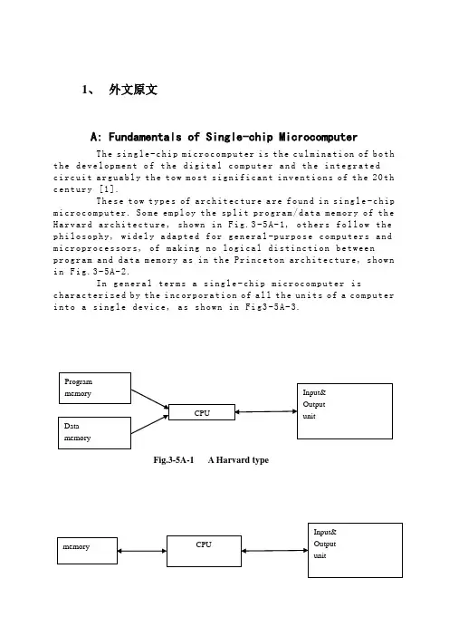
1、外文原文A: Fundamentals of Single-chip MicrocomputerTh e si ng le-c hi p m ic ro co mp ut er i s t he c ul mi na ti on of b oth t h e de ve lo pm en t o f t he d ig it al co m pu te r an d th e i n te gr at edc i rc ui t a rg ua bl y t h e to w m os t s ig ni f ic an t i nv en ti on s o f t he20th c e nt ur y [1].Th es e t ow ty pe s of ar ch it ec tu re a re fo un d i n s in g le-c hip m i cr oc om pu te r. So m e em pl oy t he spl i t pr og ra m/da ta m e mo ry o f th e H a rv ar d ar ch it ect u re, sh ow n in Fi g.3-5A-1, o th ers fo ll ow t he p h il os op hy, wi del y a da pt ed f or ge n er al-p ur po se co m pu te rs a nd m i cr op ro ce ss o r s, o f ma ki ng n o log i ca l di st in ct ion be tw ee np r og ra m an d d at a m e mo ry a s i n t he P r in ce to n ar ch ite c tu re, sh ow n i n F ig.3-5A-2.In g en er al te r ms a s in gl e-chi p m ic ro co mp ut er i sc h ar ac te ri zed b y t he i nc or po ra ti on of a ll t he un it s of a co mp ut er i n to a s in gl e d ev i ce, as s ho wn in Fi g3-5A-3.Fig.3-5A-1 A Harvard typeFig.3-5A-2. A conventional Princeton computerFig3-5A-3. Principal features of a microcomputerRead only memory (ROM).R OM i s us ua ll y f or th e p e rm an en t,n o n-vo la ti le s tor a ge o f an a pp lic a ti on s pr og ra m .M an ym i cr oc om pu te rs an d m ar e in te nd e d f or hi gh-v ol um e a p pl ic at io ns a n d he nc e t h e eco n om ic al m an uf act u re o f th e de vic e s re qu ir es t h at t he co nt en t s o f t he pr og ra m me m or y b e co mm it t ed pe rm a ne nt ly d u ri ng t he m an ufa c tu re o f ch ip s .Cl ea rl y, t hi s i m pl ie s ar i go ro us a pp ro ach to R OM c od e de ve l op me nt s in ce ch a ng es c an no t b e m ad e af te r m anu f a c tu re .Th is d ev e lo pm en t pr oc ess ma y in vo lv e e m ul at io n us in g a so ph is ti ca te d d e ve lo pm en t sy ste m w it h ah a rd wa re e mu la tio n c ap ab il it y as w el l as t he u se o f po we rf ul s o ft wa re t oo ls.So me m an uf act u re rs p ro vi de ad d it io na l RO M opt i on s byi n cl ud in g i n th eir r a n ge d ev ic es wi t h (or i nt en de d f o r u se w it h) u s er p ro gr am ma ble me mo ry. Th e sim p le st o f th es e i s u su al lyd e vi ce w hi ch c an o p er at e in a mi cro p ro ce ss or m od e b y u si ng s om e o f t he i np ut/o utp u t li ne s as a n a d dr es s an d da ta b us f ora c ce ss in g ex te rna l m em or y. T hi s t y pe o f de vi ce ca nb eh av ef u nc ti on al ly a s t h e si ng le ch ip mi cr oc om pu te r fro m w hi ch it is d e ri ve d al be it wi t h re st ri ct ed I/O a nd a m od if ied ex te rn alc i rc ui t. Th e u se o f th es ed ev ic es i s c om mo ne ve n i n pr od uc ti on c i rc ui ts wh er e t he vo lu me do es no t j us tif y t h e d ev el o pm en t c os ts o f c us to m o n-ch i p R OM[2];t he re c a n s ti ll be a s ig nif i ca nt sa vi ng i n I/O an d o th er c h ip s c om pa re d t o a co nv en ti on al mi c ro pr oc es so r b a se d ci rc ui t. Mo r e ex ac t re pl ace m en t fo r RO M dev i ce s ca n be o b ta in ed i n th e f o rm o f va ri an ts w it h 'p ig gy-b ack'E P RO M(Er as ab le pr o gr am ma bl e RO M )s oc ke ts o r d ev ic e s wi th EP RO M i n st ea d o f RO M 。
标准文档外文翻译院(系)专业班级姓名学号指导教师年月日Programmable designed for electro-pneumatic systemscontrollerJohn F.WakerlyThis project deals with the study of electro-pneumatic systems and the programmable controller that provides an effective and easy way to control the sequence of the pneumatic actuators movement and the states of pneumatic system. The project of a specific controller for pneumatic applications join the study of automation design and the control processing of pneumatic systems with the electronic design based on microcontrollers to implement the resources of the controller.1. IntroductionThe automation systems that use electro-pneumatic technology are formed mainly by three kinds of elements: actuators or motors, sensors or buttons and control elements like valves. Nowadays, most of the control elements used to execute the logic of the system were substituted by the Programmable Logic Controller (PLC). Sensors and switches are plugged as inputs and the direct control valves for the actuators are plugged as outputs. An internal program executes all the logic necessary to the sequence of the movements, simulates other components like counter, timer and control the status of the system.With the use of the PLC, the project wins agility, because it is possible to create and simulate the system as many times as needed. Therefore, time can be saved, risk of mistakes reduced and complexity can be increased using the same elements.A conventional PLC, that is possible to find on the market from many companies, offers many resources to control not only pneumatic systems, but all kinds of system that uses electrical components. The PLC can be very versatile and robust to be applied in many kinds of application in the industry or even security system and automation of buildings.Because of those characteristics, in some applications the PLC offers to much resources that are not even used to control the system, electro-pneumatic system is one of this kind of application. The use of PLC, especially for small size systems, can be very expensive for the automation project.An alternative in this case is to create a specific controller that can offer the exactly size and resources that the project needs [3, 4]. This can be made using microcontrollers as the base of this controller.The controller, based on microcontroller, can be very specific and adapted to only one kind of machine or it can work as a generic controller that can be programmed as a usual PLC and work with logic that can be changed. All these characteristics depend on what is needed and how much experience the designer has with developing an electronic circuit and firmware for microcontroller. But the main advantage of design the controller with the microcontroller is that the designer has the total knowledge of his controller, which makes it possible to control the size of the controller, change the complexity and the application of it. It means that the project gets more independence from other companies, but at the same time the responsibility of the control of the system stays at the designer hands2. Electro-pneumatic systemOn automation system one can find three basic components mentioned before, plus a logic circuit that controls the system. An adequate technique is needed to project the logic circuit and integrate all the necessary components to execute the sequence of movements properly.For a simple direct sequence of movement an intuitive method can be used [1, 5], but for indirect or more complex sequences the intuition can generate a very complicated circuit and signal mistakes. It is necessary to use another method that can save time of the project, makea clean circuit, can eliminate occasional signal overlapping and redundant circuits. The presented method is called step-by-step or algorithmic [1, 5], it is valid for pneumatic and electro-pneumatic systems and it was used as a base in this work.The method consists of designing the systems based on standard circuits made for each change on the state of the actuators, these changes are called steps.The first part is to design those kinds of standard circuits for each step, the next task is to link the standard circuits and the last part is to connect the control elements that receive signals from sensors, switches and the previous movements, and give the air or electricity to the supply lines of each step. In Figs. 1 and 2 the standard circuits are drawn for pneumatic and electro-pneumatic system [8]. It is possible to see the relations with the previous and the next steps.3. The method applied inside the controllerThe result of the method presented before is a sequence of movements of the actuator that is well defined by steps. It means that each change on the position of the actuators is a new state of the system and the transition between states is called step.The standard circuit described before helps the designer to define the states of the systems and to define the condition to each change betweenthe states. In the end of the design, the system is defined by a sequencethat never chances and states that have the inputs and the outputs well defined. The inputs are the condition for the transition and the outputs are the result of the transition.All the configuration of those steps stays inside of the microcontroller and is executed the same way it was designed. The sequences of strings are programmed inside the controller with 5 bytes; each string has the configuration of one step of the process. There are two bytes for the inputs, one byte for the outputs and two more for the other configurations and auxiliary functions of the step. After programming, this sequence of strings is saved inside of a non-volatile memory of the microcontroller, so they can be read and executed.The controller task is not to work in the same way as a conventional PLC, but the purpose of it is to be an example of a versatile controller that is design for an specific area. A conventional PLC process the control of the system using a cycle where it makes an image of the inputs, execute all the conditions defined by the configuration programmed inside, and then update the state of the outputs. This controller works in a different way, where it read the configuration of the step, wait the condition of inputs to be satisfied, then update the state or the outputs and after that jump to the next step and start the process again.It can generate some limitations, as the fact that this controller cannot execute, inside the program, movements that must be repeated for some time, but this problem can be solved with some external logic components. Another limitation is that the controller cannot be applied on systems that have no sequence. These limitations are a characteristic of the system that must be analyzed for each application.4. Characteristics of the controllerThe controller is based on the MICROCHIP microcontroller PIC16F877 [6,7] with 40 pins, and it has all the resources needed for thisproject .It has enough pins for all the components, serial communication implemented in circuit, EEPROM memory to save all the configuration of the system and the sequence of steps. For the execution of the main program, it offers complete resources as timers and interruptions.The list of resources of the controller was created to explore all the capacity of the microcontroller to make it as complete as possible. During the step, the program chooses how to use the resources reading the configuration string of the step. This string has two bytes for digital inputs, one used as a mask and the other one used as a value expected. One byte is used to configure the outputs value. One bytes more is used for the internal timer , the analog input or time-out. The EEPROM memory inside is 256 bytes length that is enough to save the string of the steps, with this characteristic it is possible to save between 48 steps (Table 1).The controller (Fig.3) has also a display and some buttons that are used with an interactive menu to program the sequence of steps and other configurations.4.1. Interaction componentsFor the real application the controller must have some elements to interact with the final user and to offer a complete monitoring of the system resources that are available to the designer while creating the logic control of the pneumatic system (Fig.3):•Interactive mode of work; function available on the main program for didactic purposes, the user gives the signal to execute the step. •LCD display, which shows the status of the system, values of inputs, outputs, timer and statistics of the sequence execution.•Beep to give important alerts, stop, start and emergency.• Leds to show power on and others to show the state of inputs and outputs.4.2. SecurityTo make the final application works property, a correct configuration to execute the steps in the right way is needed, but more then that itmust offer solutions in case of bad functioning or problems in the execution of the sequence. The controller offers the possibility to configure two internal virtual circuits that work in parallel to the principal. These two circuits can be used as emergency or reset buttons and can return the system to a certain state at any time [2]. There are two inputs that work with interruption to get an immediate access to these functions. It is possible to configure the position, the buttons and the value of time-out of the system.4.3. User interfaceThe sequence of strings can be programmed using the interface elements of the controller. A Computer interface can also be used to generate the user program easily. With a good documentation the final user can use the interface to configure the strings of bytes that define the steps of the sequence. But it is possible to create a program with visual resources that works as a translator to the user, it changes his work to the values that the controller understands.To implement the communication between the computer interface and the controller a simple protocol with check sum and number of bytes is the minimum requirements to guarantee the integrity of the data.4.4. FirmwareThe main loop works by reading the strings of the steps from the EEPROM memory that has all the information about the steps.In each step, the status of the system is saved on the memory and it is shown on the display too. Depending of the user configuration, it can use the interruption to work with the emergency circuit or time-out to keep the system safety. In Fig.4,a block diagram of micro controller main program is presented.5. Example of electro-pneumatic systemThe system is not a representation of a specific machine, but it is made with some common movements and components found in a real one. The system is composed of four actuators. The actuators A, B and C are double acting and D-single acting. Actuator A advances and stays in specified position till the end of the cycle, it could work fixing an object to the next action for example (Fig. 5) , it is the first step. When A reaches the end position, actuator C starts his work together with B, making as many cycles as possible during the advancing of B. It depends on how fastactuator B is advancing; the speed is regulated by a flowing control valve. It was the second step. B and C are examples of actuators working together, while B pushes an object slowly, C repeats its work for some time.When B reaches the final position, C stops immediately its cycle and comes back to the initial position. The actuator D is a single acting one with spring return and works together with the back of C, it is the third step. D works making very fast forward and backward movement, just one time. Its backward movement is the fourth step. D could be a tool to make a hole on the object.When D reaches the initial position, A and B return too, it is the fifth step.Fig. 6 shows the first part of the designing process where all the movements of each step should be defined [2]. (A+) means that the actuator A moves to the advanced position and (A−) to the initial position. The movements that happen at the same time are joined together in the same step. The system has five steps.These two representations of the system (Figs. 5 and 6) together are enough to describe correctly all the sequence. With them is possible to design the whole control circuit with the necessary logic components. But till this time, it is not a complete system, because it is missing some auxiliary elements that are not included in this draws because they work in parallel with the main sequence.These auxiliary elements give more function to the circuit and are very important to the final application; the most important of them is the parallel circuit linked with all the others steps. That circuit should be able to stop the sequence at any time and change the state of the actuators to a specific position. This kind of circuit can be used as a reset or emergency buttons.The next Figs. 7 and 8 show the result of using the method without the controller. These pictures are the electric diagram of the control circuit of the example, including sensors, buttons and the coils of the electrical valves.The auxiliary elements are included, like the automatic/manual switcher that permit a continuous work and the two start buttons that make the operator of a machine use their two hands to start the process, reducing the risk of accidents.6. Changing the example to a user programIn the previous chapter, the electro-pneumatic circuits were presented, used to begin the study of the requires to control a system that work with steps and must offer all the functional elements to be used in a real application. But, as explained above, using a PLC or this specific controller, the control becomes easier and the complexity can be increasealso.Table 2 shows a resume of the elements that are necessary to control the presented example.With the time diagram, the step sequence and the elements of the system described in Table 2 and Figs. 5 and 6 it is possible to create the configuration of the steps that can be sent to the controller (Tables 3 and 4).While using a conventional PLC, the user should pay attention to the logic of the circuit when drawing the electric diagram on the interface (Figs. 7 and 8), using the programmable controller, described in this work, the user must know only the concept o f the method and program only the configuration of each step.It means that, with a conventional PLC, the user must draw the relationbetween the lines and the draw makes it hard to differentiate the steps of the sequence. Normally, one needs to execute a simulation on the interface to find mistakes on the logicThe new programming allows that the configuration of the steps be separated, like described by the method. The sequence is defined by itself and the steps are described only by the inputs and outputs for each step.The structure of the configuration follows the order:1-byte: features of the step;2-byte: mask for the inputs;3-byte: value expected on the inputs;4-byte: value for the outputs;5-byte: value for the extra function.Table 5 shows how the user program is saved inside the controller, this is the program that describes the control of the example shown before.The sequence can be defined by 25 bytes. These bytes can be dividedin five strings with 5 bytes each that define each step of the sequence (Figs. 9 and 10).7. ConclusionThe controller developed for this work (Fig. 11) shows that it is possible to create a very useful programmable controller based on microcontroller. External memories or external timers were not used in case to explore the resources that the microcontroller offers inside. Outside the microcontroller, there are only components to implement the outputs, inputs, analog input, display for the interface and the serial communication.Using only the internal memory, it is possible to control a pneumatic system that has a sequence with 48 steps if all the resources for all steps are used, but it is possible to reach sixty steps in the case of a simpler system.The programming of the controller does not use PLC languages, but a configuration that is simple and intuitive. With electro-pneumatic system, the programming follows the same technique that was used before to design the system, but here the designer work s directly with the states or steps of the system.With a very simple machine language the designer can define all the configuration of the step using four or five bytes. It depends only on his experience to use all the resources of the controller.The controller task is not to work in the same way as a commercial PLC but the purpose of it is to be an example of a versatile controller that is designed for a specific area. Because of that, it is not possible to say which one works better; the system made with microcontroller is an alternative that works in a simple way.应用于电气系统的可编程序控制器约翰 F.维克里此项目主要是研究电气系统以及简单有效的控制气流发动机的程序和气流系统的状态。
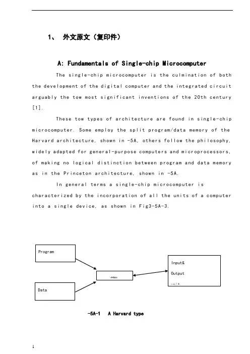
1、外文原文(复印件)A: Fundamentals of Single-chip MicrocomputerTh e si ng le-ch i p mi cr oc om pu ter is t he c ul mi nat i on o f bo th t h e d ev el op me nt o f th e d ig it al com p ut er an d t he int e gr at ed ci rc ui ta r gu ab ly th e t ow m os t s i gn if ic ant i nv en ti on s o f t h e 20t h c en tu ry[1].Th es e to w typ e s of a rc hi te ctu r e ar e fo un d i n s in gl e-ch ip m i cr oc om pu te r. So m e em pl oy t he sp l it p ro gr am/d ata me mo ry o f th e H a rv ar d ar ch it ect u re, sh ow n i n -5A, ot he rs fo ll ow th e ph i lo so ph y, w i de ly a da pt ed fo r g en er al-p ur pos e c om pu te rs an d m i cr op ro ce ss or s, o f m a ki ng no lo gi c al di st in ct io n b e tw ee n p ro gr am a n d da t a m em ory a s i n th e Pr in cet o n ar ch it ec tu re,sh ow n in-5A.In g en er al te r ms a s in gl e-chi p m ic ro co mp ut er i sc h ar ac te ri zed b y the i nc or po ra tio n of al l t he uni t s o f a co mp ut er i n to a s in gl e dev i ce, as s ho wn in Fi g3-5A-3.-5A-1 A Harvard type-5A. A conventional Princeton computerFig3-5A-3. Principal features of a microcomputerRead only memory (ROM).R OM i s u su al ly f or th e p er ma ne nt, n o n-vo la ti le s tor a ge o f an a pp lic a ti on s pr og ra m .M an ym i cr oc om pu te rs an d mi cr oc on tr ol le r s a re in t en de d fo r h ig h-v ol ume a p pl ic at io ns a nd h en ce t he e co nom i ca l ma nu fa ct ure of t he d ev ic es r e qu ir es t ha t the co nt en ts o f the pr og ra m me mo ry b e co mm it te dp e rm an en tl y d ur in g th e m an uf ac tu re o f c hi ps . Cl ear l y, th is im pl ie sa ri g or ou s a pp roa c h t o R OM co de d e ve lo pm en t s in ce c ha ng es ca nn otb e m ad e af te r man u fa ct ur e .T hi s d e ve lo pm en t pr oce s s ma y in vo lv e e m ul at io n us in g a s op hi st ic at ed deve lo pm en t sy st em w i th a ha rd wa re e m ul at io n ca pa bil i ty a s we ll a s th e u se of po we rf ul so ft wa re t oo ls.So me m an uf act u re rs p ro vi de ad d it io na l RO M opt i on s byi n cl ud in g i n th ei r ra ng e de vi ce s wi th (or i nt en de d fo r us e wi th) u s er pr og ra mm ab le m em or y. Th e s im p le st of th es e i s us ua ll y d ev ice w h ic h ca n op er ate in a m ic ro pr oce s so r mo de b y usi n g so me o f th e i n pu t/ou tp ut li ne s as a n ad dr es s an d da ta b us f or acc e ss in g e xt er na l m e mo ry. T hi s t ype o f d ev ic e c an b e ha ve fu nc ti on al l y a s t he si ng le c h ip mi cr oc om pu te r fr om wh ic h i t i s de ri ve d a lb eit w it h r es tr ic ted I/O an d a mo di fie d e xt er na l ci rcu i t. T he u se o f t h es e RO Ml es sd e vi ce s is c om mo n e ve n in p ro du ct io n c ir cu it s wh er e t he v ol um e do es n o t ju st if y th e d e ve lo pm en t co sts of c us to m on-ch i p RO M[2];t he re c a n st il l b e a si g ni fi ca nt s a vi ng in I/O a nd ot he r c hi ps co mp ar ed t o a c on ve nt io nal mi cr op ro ce ss or b as ed c ir cu it. M o re e xa ctr e pl ac em en t fo r RO M d ev ic es c an b e o bt ai ne d in t he f o rm o f va ri an ts w i th 'pi gg y-ba ck'EP RO M(Er as ab le p ro gr am ma bl e ROM)s oc ke ts o rd e vi ce s w it h EP ROM i ns te ad o f R OM 。
(完整word版)电气工程及其自动化专业外语作文A s a student, you will learn to apply related subjects such as computer technology,industrial electronics, instrumentation,electrical machines, robotics,power electronics,and automated control systems.作为一名学生,你将学会运用相关学科,如计算机技术,工业电子,仪器仪表,电器机械,机器人技术,电力电子和自动化控制系统。
Y ou will be able to understand written and oral instructions,as well as design, install, test,modify, troubleshoot,and repair electrical systems.您将能够理解书面和口头说明,以及设计,安装,测试,修改,故障排除和修复电力系统.U pon graduation,students of the Electrical Engineering Technology –Process Automation program can approach industrial electrical and electronic systems from the viewpoint of analysis,technical evaluation, design, and development。
The six—semester program concentrates on the in-depth study of electrical and electronic principles as they apply to automated systems using programmable logic controllers。
电气专业毕业设计英文文献电气专业毕业设计英文文献外文资料与中文翻译外文资料:Relay protection present situation anddevelopment一、Relay protection development present situationElectrical power system's swift development to the relay protection proposed unceasingly the new request, the electronic technology, the computer technology and communication's swift development unceasingly has infused the new vigor for the relay protection technology's development, therefore, the relay protection technology is advantageous, has completed the development 4 historical stage in 40 remaining years of time.After the founding of the nation, our country relay protection discipline, the relay protection design, the relay factory industry and the relay protection technical team grows out of nothing, has passed through the path which in about 10 year the advanced countries half century pass through. In the 50s, our country engineers and technicians creatively absorption, the digestion, have grasped the overseas advanced relay protection equipment performance and the movement technology [1], completed one to have the deep relay protection theory attainments and the rich service experience's relay protection technical team, and grew the instruction function to the national relay protection technical team's establishment. The Achengrelay factory introduction has digested at that time the overseas advanced relay technique of manufacture, has established our country own relay manufacturing industry.Therefore our country has completed the relay protection research, the design, the manufacture, the movement and the teaching complete system in the 60s. This is the mechanical and electrical -like relay protection prosperous time, was our country relay protection technology development has laid the solid foundation.From the late 50s, the transistor relay protection was starting to study. In the 60s to the 80s in is the time which the transistor relay protection vigorous development and widely uses. And the Tianjin University and the Nanjing Electric power Automation Plant cooperation research's 500kv transistor direction high frequency protection develops with the Nanjing Electric power Automation Research institute the transistor high frequency block system is away from the protection, moves on the Gezhou Dam 500 kv lines [2], finished the 500kv line protection to depend upon completely from the overseas import time.From the 70s, started based on the integration operational amplifier's integrated circuit protection to study. Has formed the complete series to the late 80s integrated circuit protection, substitutes for the transistor protection gradually. The development which, the production, the application protected to the early 90s integrated circuit were still in the dominant position, this was theintegrated circuit protection time. The integrated circuit power frequency change quantity direction which develops in this aspect Nanjing Electric power Automation Research institute high frequency protected the influential role [3], the Tianjin University and the Nanjing Electric power Automation Plant cooperation development's integrated circuit phase voltage compensation type direction high frequency protection alsomoved in many 220kv and on the 500kv line.Our country namely started the computer relay protection research from the late 70s [4], the institutions of higher learning and the scientific research courtyard institute forerunner's function. Huazhong University of Science and Technology, the Southeast University, the North China electric power institute, Xi'an Jiaotong University, the Tianjin University, Shanghai Jiaotong University, the Chongqing University and the Nanjing Electric power Automation Research institute one after another has developed the different principle, the different pattern microcomputer protective device. in 1984 the original North China electric power institute developed the transmission line microcomputer protective device first through the appraisal, and obtained the application in the system [5], has opened in our country relay protection history the new page, protected the promotion for the microcomputer to pave the way. In the main equipment protection aspect, the generator which the Southeast University and Huazhong University of Science and Technology develops loses magnetism protection, the generator protection and the generator? Bank of transformers protectionalso one after another in 1989, in 1994 through appraisal, investment movement. The Nanjing Electric power Automation Research institute develops microcomputer line protective device alsoin 1991 through appraisal. Tianjin University and Nanjing Electric power Automation Plant cooperation development microcomputer phase voltage compensation type direction high frequency protection, Xi'an Jiaotong University and Xuchang relay factory cooperation development positive sequence breakdown component direction high frequencyprotection also one after another in 1993, in 1996 through appraisal. Hence, the different principle, the different type's microcomputer line and the main equipment protect unique, provided one group of new generation performance for the electrical power system to be fine, the function was complete, operation reliable relay protection installment. Along with the microcomputer protective device's research, in microcomputer aspects and so on protection software, algorithm has also made many theory progresses. May say that started our country relay protection technology from the 90s to enter the time which the microcomputer protected.二、future development of Relay protectionThe future trend of relay protection technology is to computerization, networking is intelligent, protect, control, measure and data communication developing by integration. The principles of protection of electric power circuits are quite independent of the relay designs which may be applied. For example, if the current to an electriccircuit or a machine is greater than that which can be tolerated, it is necessary to take remedial action. The device for recognizing the condition and initiating corrective measures would be termed as an over-current relay regardless of the mechanists by whichthe function would be accomplished. Because the functions of electromechanical devices are easily described, their performance wills ever as a basis for presenting a description of relays and relay systemsin general.Relays must have the following characteristics: Reliability---The nature of the problem is that the relay may be idle for periods extending into years and then be required tooperatewith fast responds, as intended, the first time. The penalty for failure to operate properly may run into millions of dollars.Selectivity---The relay must not respond to abnormal, but harmless, system conditions such as switching transients or sudden changes in load.Sensitivity---The relay must not fail to operate, even in borderline situations, when operation was planned.Speed---The relay should make the decision to act as close to instantaneously as possible. If intentional time delay is available, it should be predictable and precisely adjustable.Instantaneous---The term means no intentional time delay.There are several possible ways to classify relays: by function, by construction, by application. Relays are one of two basic types of construction: electromagnetic or solid-state. The electromagnetic type relies on the development of electromagnetic forces on movable members,which provide switching action by physically opening or closing sets of contacts. The solid state variety provides switching action with no physical motion by changing the state of serially connected solid state component from no conducting to conducting(or vice versa). Electromagnetic relays are older and more widely used; solid state relays are more versatile, potentially more reliable, and fast.1)ComputerizationWith swift and violent development of computer hardware, computer protect hardware develop constantly even. The power system is improving to the demand that the computer protects constantly, besides basic function protected, should with trouble information of the large capacity and data the long-term parkingspace also, fast data processing function, strong communication capacity, network in order to share the whole system data , information , ability , network of resource with other protection , control device , dispatcher, high-level language programming ,etc.. This requires computer protector to have function which is equivalent to a pc machine. In computer is it develop initial stage to protect, is it make with one minicom relay protection install to imagine. Because the small-scale organism was accumulated greatly, with high costs at that time, dependability was bad, this imagined it was unrealistic . Now, exceed the minicomputer of those years greatly with computer protector size similar worker function , speed , memory capacity of accusing of machine, so make with complete sets of worker person who accuse of opportunity of relay protection already ripe, this will be one of the developing direction that a computer is protected . Tianjin university is it spend whom transformation act as continue the electric protector with computer protector structure self-same one worker person whoaccuse of to develop into already. The advantage of this kind of device is as follows, (1)it have functions of 486pc,it can meet to at present and it is various kinds of function demand where computerprotect future. (2)The size and structure are similar to present computer protector , the craft is superior, takes precautions against earthquakes , defends overheatedly and defending the electromagnetic ability of interfering strongly, can operate it in very abominable working environment , the cost is acceptable.(3)Adopting std bus or pc bus, hardware module , can select different module for use to different protection wantonly , it is flexible , easy to expand to dispose.It is an irreversible development trend to continue the computer , computerization of the electric protector. But to how better meet power system demand, how about raise the dependability of relay protection further, how make heavy economic benefits and social benefit, need carry on concrete deep research.2) NetworkedComputer network become the technological pillar of information age as message and data communication tool, made the mankind producing , basic change has taken place in the appearance with social life. It isinfluencing each industrial field deeply, has offered the powerful communication means for each industrial field too. Up till now, except that protect differentially and unite protecting vertically, all continue electric protector can only react that protect the electric quantity of installing office. The function of relay protection is only limited to excising the trouble component too , narrow the accident coverage. This mainly lack the powerful data communication means. Having already put forward the concept protected systematically abroad, this meant the safe automatics mainly at that time. Because the function of relay protection is not only limited to excising the trouble component and restriction accident coverage (this is primary task), the peace and steadiness that will be guaranteed the whole system run . This require each protect unit can share the whole operation and data , trouble of information of system, each protect unit and coincident floodgate device coordination on the basis of analysing the information and data, guarantee systematic peace and steadiness run . Obviously , realize the primary condition that system protect the whole system every protector of capitalequipment link with the computer network, namely the one that realized the computer protector is networked. This is totally possible under present technological condition .To general protecting systematically , realize the computer networking of the protector has a very great advantage too. It continue electric trouble not the less many in information not systematic can receiving protector ,for trouble nature , judgement and the trouble,trouble of position from measuring the less accurate. Protect to self-adaptation research of principle pass long time very already , make certain achievement too, but should really realize protecting the self-adaptation to the operation way of the system and trouble state, must obtain more system operating and trouble information , the computer that only realizes protecting is networked, could accomplish this . As to the thing that some protectors realize computer networking , can improve the dependability protected . Tianjin Sanxia vltrahigh voltage many return circuit bus bar , 500kv of power station , put forward one distributed principle that bus bar protected to future 1993 such as university, succeed in developing this kind of device tentatively. Principle its bus bar is it disperse several (with protect into bus bar back to way the same ) bus bar protect Entrance to protect traditional concentration type, disperse and install it in every return circuit is protected and rejected , each protect the unit to link with the computer network, each one protects the electric current amount that the unit only inputs a return circuit , after changing it into figure amount, convey to the protection units of other return circuits through the computer network, each protect the unit according to the electric current amount of this return circuit and electric current amount of other return circuits gotfrom computer network, carry on bus bar differential calculation that protect, if result of calculation prove bus bar trouble jump format return circuit circuit breaker only, isolate the bus bar of the trouble. At the time of the trouble outside the bus bar district , each protect the unit and calculate for movements of the external trouble. This kind protect principle by distributed bus barthat network realize with computer, bus bar protect principle have higher dependability than traditional concentration type. Because if one protect unit interfere or mistake in computation and when working up by mistake, can only jump format return circuit , can is it make bus bar to be whole of malignant accident that excise to cause wrong, this is very important to systematic pivot with supervoltage bus bar of hydropower station like SanxiaCan know computer protector networked to can raise and protect the performance and dependability greatly while being above-mentioned, this is an inexorable trend that a computer protects development 3) Protect , control , measure , data communication integratesOn terms that realize computerization of relay protection and networked, the protector is a high performance , multi-functional computer in fact, it is a intelligent terminal on the computer network of whole power system. It can obtain any information and data of operating and trouble of the power system from network , can convey network control centre or any terminal function , and can also finish the measurement , control , data communication function in there is no normal running of trouble cases, namely realize protecting ,controlling , measuring , data communication integrates.At present, for measurement, need that protects and controlling, all equipment of the outdoor transformer substation, two voltage, electric current of voltage transformer, circuit,etc. must with control cable guide to the top management room for instance. Lay control cable take a large amount of investment, make the very much complicated returncircuit 2 times in a large amount. But if above-mentioned protection, control, measure, data communication integrated computer device, install in to is it by the equipment , protect into voltage , electric current amount of equipment in device this after changing into the figure amount to protect outdoor transformer substation on the spot, send to the top management room through the computer network, can avoid a large number of controlcables . If use optic fibre as the transmission medium of the network , can avoid and interfere electromagnetically. The photocurrent mutual inductor of now (ota ) and photovoltage mutual inductor (otv ) have been already during the course of studying and testing, must get application in the power system in the future. In case of adopting ota and otv, namely should be putting and is being protected near the equipment.After the optical signals of ota and otv are input in the integrated device here and changes into an electric signal, what is on one hand uses as being protected calculation is judged ; As measurement amount on the other hand, send to the top management room through the network. Can to protect operation of equipment control order send this integrated device to through network from top management room, therefore the integrated device carries out the operation of the circuit breaker. The university of Tianjin put forward protecting,controlled , measured , communication integration in 1992, develop based on tms320c25 digital signal processor (dsp ) first protecting , control , measure , the integrated device of data communication.4)IntelligentIn recent years, if artificial intelligence technology neural network, hereditary algorithm, evolve plan , fuzzy logic ,etc. get application in power system all field, the research that is used in the field of relay protection has already begun too. Neural network one non-linear method that shine upon, a lot of difficult to list equation or difficult in order to the complicated non-linear question that is solved, use the method of the neural network to be very easily solved .For example the short circuit of crossing the resistance of courseof emergence is a non-linear problem in transmit electricity in the systematic electric potential angle of both sides of line and lay cases, it is very difficult to make discrimination , trouble of position while being correct for distance to protect, is it work up or is it work up to refuse by mistake to lead to the fact; If use neural network method, through a large number of trouble training of sample, so long as sample centralized to fully consider various kinds of situations, can differentiate correctly while any trouble takes place. Other if hereditary algorithm , is it is it have is it solve complicated abilityof problem to asking unique their too to plan to evolve. Artificial intelligence the being method proper to is it can make it solve speed to be fast not to ask to combine. Can predict , the artificial intelligence technology must get application in the field of relay protection, in order to solve the problem difficult to solvewith the routine method.中文翻译:继电保护的现状与发展一、继电保护发展现状电力系统的飞速发展对继电保护不断提出新的要求,电子技术、计算机技术与通信技术的飞速发展又为继电保护技术的发展不断地注入了新的活力,因此,继电保护技术得天独厚,在40余年的时间里完成了发展的4个历史阶段。
An Expert System for Transformer Fault Diagnosis Using Dissolved Gas Analysis1. INTRODUCTIONThe power transformer is a major apparatus in a power system, and its correct functioning its vital to minimize system outages, many devices have evolved to monitor the serviceability of power transformers. These devices, such as, Buchholz relays or differential relays, respond only to a severe power failure requiring immediate removal of the transformer from service, in which case, outages are inevitable. Thus, preventive techniques for early detection faults to avoid outages would be valuable. In this way, analysis of the mixture of the faulty gases dissolved in insulation oil of power transformer has received worldwide recognition as an effective method for the detection of oncipient faults. Many researchers and electrical utilities have reported on their experience and developed interpretative criteria on the basis of DGA. However, criteria tend to vary from utility to utility. Therefore, transformer diagnosis is still in the heuristic stage. For this reason, knowledge-based programming is a suitable approach to implement in such a diagnostic problem.Based on the interpretation of DGA, a prototype of an expert system for diagnosis of suspected transformer faults and their maintenance procedures is proposed. The significant source in this knowledge base is the gas ratio method. Some limitations of this approach are overcome by incorporating the diagnostic procedure and the synthetic expertise method. Furthermore, data bases adopted from TPC'S gas records of transformers are incorporated into the expert system to increase the practical performance. Uncertainty of diagnosis is managed by using fuzzy set concepts. This expert system is constructed with rule based knowledge representation, since it can be expressed by experts. The expert system building tool,knowledge Engineering System(KES), is used in the development of the knowledge system because, it has excellent man-machine interface that provides suggestions. Moreover,its inference strategy is similar to the MYCIN. A famous rule-based expert system used for medical diagnosis. The uncertainty of human qualitative diagnostic expertise, e.g., key gasanalysis, and another quantitative imprecision, such as, norms threshold and gas ratio boundaries etc., are smoothed by appropriate fuzzy models. With the results of such implementation, different certainty factors will be assigned to the corresponding expertise variables. Both event-driven(forward chaining) and goal-driven (backward chaining) inferences are used in the inference engine to improve the inference efficiency. To demonstrate the feasibility of the proposed expert system, around hundreds of TPC historical gas records have been tested. It is found that more appropriate faulty types and maintenance suggestions can support the maintenance personals to increase the performance of transformer diagnosis.2. DEVELOPMENT OF DIAGNOSIS AND INTERPRETATIONLike many diagnostic problems, diagnosis of oil-immersed power transformer is a skilled task. A transformer may function well externally with monitors, while some incipient deterioration may occur internally to cause a fatal problem in the latter development. According to a Japanese experience, nearly 80% of all faults result from incipient deteriorations. Therefore, faults should be identified and avoided at the earliest possible stage by some predictive maintenance technique. DGA is one of the most popular techniques for this problem. Fault gases in transformers are generally produced by oil degradation and other insulating material, e.g., cellulose and paper. Theoretically, if an incipient or active fault is present, the individual dissolved gas concentration, gassing rate, total combustible gas(TCG) and cellulose degradation are all significantly increased. By using gas chromatography to analyse the gas dissolved in a transformer's insulating oil, it becomes feasible to judge the incipient fault types. This study is concerned with the following representative combustible gases; hydrogen(H2), methane(C2H2), ethane(C2H6), ethylene(C2H2) and carbon monoxide(C0).Many interpretative methods based on DGA to the nature of incipient deterioration have been reported. Even under normal transformer operational conditions, some of these gases may be formed inside. Thus, it is necessary to build concentration norms from a sufficiently large sampling to assess the statistics. TPC investigated gas data from power transformers to construct its criteria. The developedknowledge base in this paper is partially based on these data. On the hand, Dornerburg developed a method to judge different faults by rating pairs of concentrations of gases, e.g., CH/H, GH/C3H4, with approximately equal solubility and fusion coefficients. Rogers established mare comprehensive ratio codes to interpret the thermal fault types with theoretical thermodynamic assessments. This gas ratio method was promising because it eliminated the effect of oil volume and simplified the choice of units. Moreover, it systematically classified the diagnosis expertise in a table form. Table 1 displays the ratio method as proposed by Rogers. The dissolved gas may vary with the nature and severity of different faults. By analyzing the energy density of faults, it's possible to distinguish three basic fault processes:overheating(pyrolysis), corona(partial dischatge) and arcing discharge. Corona and arcing arise from electrical faults, while overheating is a thermal fault. Both types of faults my lead to deterioration, while damage from overheating is typically less than that from electrical stress. Infect, different gas trends lead to different faulty types, the key gas method is identified. For example, large amounts of CH and H are produced with minor arcing fault 4 quantities of CH 2aid C2H2 may bea symptom of an arcing fault.3.THE PROPOSED DIAGNOSTIC EXPERT SYSTEMThis study is aimed at developing a rule-based expert system to perform transformer diagnosis similar to a human expert. The details of system processing are described below.3.1 The Proposed Diagnostic MethodDiagnosis is a task that requires experience. It is unwise to determine an approach from only a few investigations. Therefore, this study uses the synthetic expertise method with the experienced procedure to assist the popular gas ratio method and complete practical performance.3.1.1 Experienced Diagnostic ProcedureThe overall procedure of routine maintenance for transformers is listed. The core of this procedure is based on the implementation of the DGA technique. The gas ratio method is the significant knowledge source. Some operational limitations of the gasratio method exist. The ratio table is unable to cover all possible cases. Minimum levels of gases must be present. The solid insulation involving CO and CO are handled separately and the gas ratio codes have been developed mainly from a free-breathing transformer. Other diagnostic expertise should be used to assist this method. Norms, synthetic expertise method and data base records have been incorporated to complete these limitations. The first step of this diagnostic procedure begins by asking DGA for an oil sample to be tested. More important relevant information about the transformer's condition, such as the voltage level, the preservative type, the on-line-tap-changer(OLTC) state, the operating period and degassed time must be known for further inference. Norms(criteria) Set up by TPC power transformers' gas characteristic data are then used to judge the transformers' condition. For the abnormal cases, the gas ratio method is used to diagnose transformer fault type. If different or unknown diagnosis results are found from these ratio methods, a further synthetic expertise method is adopted. After these procedures, different severity degrees are assigned to allow appropriate corresponding maintenance suggestions.3.1.2 Synthetic Expertise MethodThe ratio trend, norms threshold, key gas analysis and some expertise are considered as different evidences to confirm some special fault types. In other words, more significant evidences have been collected for some special fault type, better assessment of the transformer status is obtained.The ratio trend can be seen as a modification of the conventional gas ratio and key gas method.Obviously, the above gas trends should be incorporated with other evidences under the experienced procedure for practical use. Norms threshold, the gassing rate, the quantity of total combustible gas(TCG), the TPC maintenance expertise and the fuzzy set assignment are all important evidences considered in the synthetic diagnosis.Other expertise based on a transformer historical data base is also used to analyse the characteristics of a case transformer. Section 3.4 gives some details of these rules.3.2 Expert System StructureThe proposed diagnostic expert system is composed of components, working memory, a knowledge base, an inference engine and a man-machine interface. Working memory (global data base) contains the current data relevant to solve the present problem. In this study, most of the diagnostic variables stored in the data base are current gas concentration, some are from the user, others are retrieved from the transformer's historical data base. Note that the fuzzy set concept is incorporated to create fuzzy variables on the request of system reasoning. A knowledge relationship, which uses these facts, as the basis for decision making. The production rule used in this system is expressed in IF-THEN forms. A successful expert system depends on a high quality knowledge base. For this transformer diagnostic system, the knowledge base incorporates some popular interpretative methods of DGA, synthetic expertise method and heuristic maintenance rules. Section 3.4 will describe this knowledge base. Another special consideration in the expert system is its inference engine. The inference engine controls the strategies of reasoning and searching for appropriate knowledge. The reasoning strategy employs both forward chaining(data-driven) and backward chaining(goal-driven). Fuzzy rules, norms rules, gas ratio rules, synthetic expertise rules and some of the maintenance rules and some maintenance rules, use forward chaining.As for the searching strategy in KES, the depth first searching and short-circuit evaluation are adopted. The former can improve the search efficiency by properly arranging the location of significant rules in the inference procedures. The latter strategy only searches the key conditional statements in the antecedent that are responsible for establishing whether the entire rule is true or false. Taking the advantages of these two approaches in the building and structuring of a knowledge base improves inference efficiency significantly.As for man-machine interface. KES has an effective interface which is better than typical knowledge programming languages, such as, PROLOG or LISP. With the help of this interface, the capability of tracing, explaining and training in an expert system is greatly simplified.4.IMPLEMENTATION OF THE PROPOSED EXPERT SYSTEMAn expert system is developed based on the proposed interpretative rules and diagnostic procedures of the overall system. To demonstrate the feasibility of this expert system in diagnosis, the gas data supported by MTL of TPC have been tested. In Taiwan, the MTL of TPC performs the DGA and sends the results to all acting divisions relating to power transformers. In return, these acting divisions are requested to collect and supply their transformer oil samples periodically.After analysing oil samples, more than ten years' worthy gas records are collected and classified into three voltage level, 69KV, 16KV and 345KV. Thus, gas records for one transformer are composed of several groups of data. In the process of DGA interpretation, all of these data may be considered, but only the recent data which have significant effects on diagnosis are listed in the later demonstration. In MTL, all gas concentrations are expressed by pm in volume concentration. 100 pm is equal to 0.01 ml(gas)/100ml(oil).From the expertise of diagnosis, the normal state can be confirmed only by inspection of the transformer's norms level. In practice, most of the transformer oil samples are normal, and this can be inferred successfully on the early execution of this expert system. However, the Success of an expert system is mainly dependent on the capability of diagnosis for the transformers in question. In the implementation, many gas records which are in abnormal condition are chosen to test the Justification of this diagnostic system. A total of 101 transformer records have been executed and the results are summarized in Table 5. Among those implemented, three are listed and demonstrated.Shown in Table 5 are the results of 101 units of transformers in three types of remedy: normal, thermal fault and arc fault. After comparing them with the actual state and expert judgement, a summary of results was obtained. As previously stated, one unit of transformer may include many groups of gas data. In evaluation, we depicted some key groups in one unit to justify because some transformers may have different incipient faults during different operational stages. Some mistakes implemented from testing are caused by the remaining oil in the oil sampling container, unstable gas characteristics of the new degassing sample and some obscuregas types. If more information or new techniques support other uncertain membership functions, they can be added into the knowledge has to enlarge the the performance of this prototype expert system. Furthermore, the parameters described in table 2,3 and 4 are suitable for TPC power transformer. Different regions may be modified the maintenance personnel find more suitable system parameters.5.CONCLUSIONSA prototype expert system is developed on a personal computer using KES. It can diagnose the incipient faults of the suspected transformers and suggest proper maintenance actions. Fuzzy set concept is used to handle uncertain norms thresholds, gas ratio boundaries and key gas analysis. The synthetic method and diagnostic procedure are proposed to assist the situation which can not be handled properly by the gas ratio methods. Results from the implementation of the expert system shows that the expert system is a useful tool to assist human expert and maintenance engineers.The knowledge base of this expert system is incorporated within the popular interpretative method of DGA, synthetic expertise and heuristic maintenance rules. The data base supported by TPC MTL for about 10 year collection of transformer inspection data is also used to improve the interpretation of diagnosis. Through the development of the proposed expert system, the expertise of TPC MTL can be reserved. In addition, this work can be continued to expand the knowledge base by adding any new experience, measurement and analysis techniques.。
电气工程的外文文献(及翻译)文献一:Electric power consumption prediction model based on grey theory optimized by genetic algorithms本文介绍了一种基于混合灰色理论与遗传算法优化的电力消耗预测模型。
该模型使用时间序列数据来建立模型,并使用灰色理论来解决数据的不确定性问题。
通过遗传算法的优化,模型能够更好地预测电力消耗,并取得了优异的预测结果。
此模型可以在大规模电力网络中使用,并具有较高的可行性和可靠性。
文献二:Intelligent control for energy-efficient operation of electric motors本文研究了一种智能控制方法,用于电动机的节能运行。
该方法提供了一种更高效的控制策略,使电动机能够在不同负载条件下以较低的功率运行。
该智能控制使用模糊逻辑方法来确定最佳的控制参数,并使用遗传算法来优化参数。
实验结果表明,该智能控制方法可以显著降低电动机的能耗,节省电能。
文献三:Fault diagnosis system for power transformers based on dissolved gas analysis本文介绍了一种基于溶解气体分析的电力变压器故障诊断系统。
通过对变压器油中的气体样品进行分析,可以检测和诊断变压器内部存在的故障类型。
该系统使用人工神经网络模型来对气体分析数据进行处理和分类。
实验结果表明,该系统可以准确地检测和诊断变压器的故障,并有助于实现有效的维护和管理。
文献四:Power quality improvement using series active filter based on iterative learning control technique本文研究了一种基于迭代研究控制技术的串联有源滤波器用于电能质量改善的方法。
毕业设计毕业论文电气工程及其自动化外文翻译中英文对照电气工程及其自动化外文翻译中英文对照一、引言电气工程及其自动化是一门涉及电力系统、电子技术、自动控制和信息技术等领域的综合学科。
本文将翻译一篇关于电气工程及其自动化的外文文献,并提供中英文对照。
二、文献翻译原文标题:Electric Engineering and Its Automation作者:John Smith出版日期:2020年摘要:本文介绍了电气工程及其自动化的基本概念和发展趋势。
首先,介绍了电气工程的定义和范围。
其次,探讨了电气工程在能源领域的应用,包括电力系统的设计和运行。
然后,介绍了电气工程在电子技术领域的重要性,包括电子设备的设计和制造。
最后,讨论了电气工程与自动控制和信息技术的结合,以及其在工业自动化和智能化领域的应用。
1. 介绍电气工程是一门研究电力系统和电子技术的学科,涉及发电、输电、配电和用电等方面。
电气工程的发展与电力工业的发展密切相关。
随着电力需求的增长和电子技术的进步,电气工程的重要性日益凸显。
2. 电气工程在能源领域的应用电气工程在能源领域的应用主要包括电力系统的设计和运行。
电力系统是由发电厂、输电线路、变电站和配电网络等组成的。
电气工程师负责设计和维护这些设施,以确保电力的可靠供应。
3. 电气工程在电子技术领域的重要性电气工程在电子技术领域的重要性体现在电子设备的设计和制造上。
电子设备包括电脑、手机、电视等消费电子产品,以及工业自动化设备等。
电气工程师需要掌握电子电路设计和数字信号处理等技术,以开发出高性能的电子设备。
4. 电气工程与自动控制和信息技术的结合电气工程与自动控制和信息技术的结合是电气工程及其自动化的核心内容。
自动控制技术可以应用于电力系统的运行和电子设备的控制,以提高系统的稳定性和效率。
信息技术则可以用于数据采集、处理和传输,实现对电力系统和电子设备的远程监控和管理。
5. 电气工程在工业自动化和智能化领域的应用电气工程在工业自动化和智能化领域的应用越来越广泛。
西南交通大学本科毕业设计外文翻译年级:学号:姓名:专业:指导老师xx 年xx、月院系 xxx 专业电气工程及其自动化年级 xx 姓名 xxx题目外文翻译指导教师评语指导教师 (签章)评阅人评语评阅人 (签章) 成绩答辩委员会主任 (签章)年月日目录ABSTRACT (1)I. INTRODUCTION (1)II. DESIGN OF HARDWARE FOR TEMPERATURE CONTROL SYSTEM (2)III. DESIGN OF SIGNAL WIRELESS TRANSMISSION (3)IV. SOFTWARE DESIGN (4)V. CONCLUSION (11)REFERENCES (12)摘要 (13)I 介绍 (13)II 对温度控制系统的硬件是合计 (13)III 设计信号的无线传输 (14)IV 软件设计 (15)V 结论 (19)Design of Temperature Control Device Underground Coal Mine Based on AT89S52ABSTRACTAbstract-Temperature underground coal mine is an important index, especially for mining workers underground. To monitor the temperature effectively, a temperature measurement and control system is necessary to design. Temperature value is displayed on LED screen on line. When temperature value reaches the maximum, conditioning device connected with the opening end of the relay controlled by the MeV will start up. Temperature signal and control information is all transmitted by wireless signal transmission module nRF905. The system program consists of transducer control and display of the temperature value. The control program of transducer is compiled according to its communication protocol. Program of wireless data transmission should be debugged between the data transmission modules. Alarm device is designed to provides effective information to workers when the temperature value is unusual. Thus monitoring of the temperature underground coal mine can be real and effective.Keywords: Index Terms-DS18B20, AT89S52, nRF905, coal mine temperature controlI. INTRODUCTIONThe environment underground coal mine is poor, and various dangers can easily occur. Therefore, in order to ensure safe production of coal mine, it is needed to supervise various parameters underground coal mine, including temperature, pressure, gas, wind speed and distance. Timely monitoring temperatures of some mine key points and coal face is an important monitoring project to guaranteesafe production. Moreover, the ultrasonic measurement of distance is usually used in coal mine, to ensure the accuracy of measurement, it is also needed to make accurate temperature measurement. Traditional temperature measurement is done by classical isolated sensors, which has some disadvantages as follows: slow reaction rate, high measuring errors, complex installation and debugging and inconvenient long-distance transmission. In this paper intelligent temperature measurement and control is realized by taking DS18B20 temperature sensor and AT89S52 MCU as platform. DS18B20 has some advantages, mainly including digital counting, direct output of the measured temperature value in digital form, less temperature error, high resolution, strong anti-interference ability, long-distance transmission and characteristic of serial bus interface. Comparing with the traditional method of temperature measurement, MCU temperature measurement can achieve storage and analysis of temperature data, remote transmission and so on. DS18B20 sensor is a series of digital single bustemperature sensor made in DALLAS company ofUSA.[I]II. DESIGN OF HARDWARE FOR TEMPERATURE CONTROL SYSTEM The device is composed of the temperature sensor DS18B20, MCU AT89S52, display module and relay for main fan control. The principle diagram of this hardware is shown in Fig.l.DS18B20 temperature sensor converts the environmental temperature into signed digital signal (with 16 bits complementary code accounting for two bytes), its output pin 2 directly connected with MCU Pl.2. Rl is pull-up resistor and the sensor uses external power supply. Pl.7 is linked to relay and PO is linked to LED display. AT89S52 is the control core of the entire device. Display modules consists of quaternity common-anode LED and four 9012. The read-write of sensor, the display of temperature and the control of relay are completed by program control ofthe system. [2]III. DESIGN OF SIGNAL WIRELESS TRANSMISSIONTested signal is transmitted by wireless mode, as shown in Fig. 1. Wire transmitting of signal underground coal mine has some disadvantages:1) The mineral products are mined by excavation of shaft and tunnel. Meanwhile, there are so many equipments used underground coal mine. Therefore, it is more difficult to wiring in shaft and tunnel, and environmental suitability is poor for wire transmitting of signals;2) Support workers should check up cables for transmitting signals at any moment when combined motion of the coal machine support occurs. Thus, workers' labor intensity is increased;3) The long-distance transmission of sensing element with contact method may lead to larger errors. To reduce errors, the long-distance line driver and safety barrier are needed. Thus, the cost is increased;4) The work load of maintenance underground coal mine is larger.Figure 1. Structure diagram of signal wireless transmission systemBy contrast, adopting wireless data transmission can effectively avoid theabove disadvantages. [3]Wireless signal transmission module nRF905 is used in the design. Its characteristics are as follows: Integrated wireless transceiver chip nRF905 works in the ISM band 433/868/915 MHz, consists of a fully integrated frequency modulator, a receiver with demodulator, a power amplifier, a crystal oscillator and a regulator. Its working mode of operation is Shock Burst. Preambles and CRC code are automatically generated in the mode, and can easily be programmed through the SPI interface. Current consumption of the module is very low. When the transmit power is +10 dBm, the emission current is 30 rnA and receiving current is 12.2 rnA. It also can enter POWERDOWN model to achieve energy-saving. [4]IV. SOFTWARE DESIGNFor doing the read-write programming for DS18B20, its read-write time sequence should be guaranteed. Otherwise, the result oftemperature measurement will not be read.Figure 2. Software design flow chartTherefore, program design for operation on DS18B20 had better adopt assembly language.[5] Software design flow chart is shown in Fig.2.Structure of Main program for temperature measurement is shown as following: INIT 1820:SETB DINNOPCLRDINMOV RO,#250TSRI: DJNZ RO,TSRINOPNOPNOPMOV RO,#60TSR2: DJNZ RO,TSR2 JNB PI.0,TSR3 LJMPTSR4TSR3: SETB FLAGI LJMPTSR5TSR4: CLR FLAG1 LJMPTSR7TSR5: MOY RO,#6BH TSR6: DJNZ RO,TSR6 TSR7: SETB DIN SETB DINRETGET TEMPER:SETB DINLCALL INIT 182018 FLAG1,TSS2RETTSS2: MOY A,#OCCH LCALL WRITE 1820 MOY A,#44HLCALL WRITE 1820 LCALL DELAYLCALL DELAY LCALLDELAYLCALL DELAY LCALLDELAY LCALL INIT 1820 MOY A,#OCCH LCALL WRITE 1820 MOY A,#OBEH LCALL WRITE 1820 LCALL READ 1820 RETWRITE 1820: MOY R2,#8CLRCREAD_l 820: MOVR4,#2MOV Rl,#29H REOO: MOV R2,#8 REOl: CLR C SETB DINNOPNOPCLRDINNOPNOPNOPSETB DINMOVR3,#9 ADJUST_TEMPER: CLR TEM_BITJNB 47H,AJUST SETB TEM_BITXRL TEMPER_L,#OFFH MOV A,TEMPER_L ADDA,#OlHMOV TEMPE~L,AXRL TEMPER_H,#OFFH MOV A,TEMPER_H ADDCA,#OOHMOV TEMPER_H,A ADJUST:MOV A,TEMPER_L MOV B,#lOODIVABMOV B_BIT,AMOV A,BMOV B,#lODIVABMOV S_BIT,AMOV G_BIT,BDISP MAIN:LCALL D_DISP LCALL G_DISP LCALL S_DISP LCALL B_DISPMOV A,#OFFH LCALLDISPMOV A,#OFFHLCALL DISPMOV A,#OFFH LCALLDISP MOV A,#OFFH LCALL DISP LCALLDELAY RETD DISP: MOVC,D_BITJC D DISPI MOV A,#03H LCALL DISP RETD DISPl:MOV A,#49H LCALL DISP RETG DISP:MOV A,G_BIT MOV DPTR,#TAB MOVC A,@A+DPTR ANLA,#OFEH LCALL DISP RETS DISP:MOV A,S_BIT MOV DPTR,#TAB MOVC A,@A+DPTR LCALL DISP RETB DISP:JNB TEM_BIT,B_DISMOV A,#OfdhLCALL DISPRETB DIS:JB l8H,B_lMOV A,#OffhLCALL DISPRETB 1: MOV A,#03HLCALL DISPRETDISP: CLRCMOVR2,#8DIS: RRCAMOVDAT,CCLRCLKSETBCLKCLRCLKDJNZ R2,DISRETDELAY: MOV R3,#80hDl: MOV R4,#OfEhDJNZ R4,$DJNZ R3,DlRETTAB:DB 03H,9FH,25H,ODH,99H DB 49H,4IH,IFH,OIH,09HENDV. CONCLUSIONThe performance of measurement-control device mainly depends on the performance of sensing element, the processing circuit and the transmission efficiency of collected data. Digital temperature sensor DSl8B20 and processing chip AT89S52 have characteristics of good technical indexes, and the field operations indicate that circuits system has many advantages, such as accurate data detection, good stability and easy adjustment.After industrial operation test, the system is excellent for worst mine environment, which provides powerful assurance for safe production in the coal industry, and brings good economic and social benefits.REFERENCES[1] WANG Furui, "Single chip microcomputer measurement and control system comprehensive design," Beijing University of Aeronautics and Astronautics Press, 1998.[2] XIA Huguo, "Technology application in automation combined-mining face," Shaanxi Coal, 2007.[3] SHA Zhanyou, "Principle and application of intelligent integrated temperature sensor," Mechanical Industry Publishing House, 2002.[4] CAO Shujuan, HE Yinyong, GUO San-rning, On-line temperaturemeasuring system involving coal mine, Journal of Heilongjiang Instituteof Science & Technology,7(2005)[5] SUN Xiaoqing, XIAO Xingming, WANG Peng, "Design of MeasuringSystem for Rotating Speed of Hoist Based on Virtual Instrument," Coal Mine Machinery, 12(2005).基于AT89S52煤矿井下的温度控制装置的设计摘要煤矿井下抽象温度是评价学术期刊的重要指标,特别是对在地下工作的采矿工。
附录:外文资料翻译外文资料原文:A Virtual Environment for Protective Relaying Evaluationand TestingA. P. Sakis Meliopoulos and George J. CokkinidesAbstract—Protective relaying is a fundamental discipline of power system engineering. At Georgia Tech, we offer three courses that cover protective relaying: an undergraduate course that devotes one-third of the semester on relaying, a graduate courseentitled “Power System Protection,” and a three-and-a- the concepts,theory, and technology associated with protective relaying, we a virtual environment. The virtual environment includes a) a power system simulator, b) a simulator of instrumentation for protective relaying with visualization and animation modules, c) specific protective relay models with visualization and animation modules, and d) interfaces to be performed. We refer to this set of software as the “virtual power system.” The virtual power system permits the in-depth coverage of the protective relaying concepts in minimum time and maximizes student understanding. The tool is not used in a passive way. Indeed, the students actively participate with well-designed projects such as a) design and implementation of multifunctional relays, b) relay testing for specific disturbances, etc. The paper describes the virtual power system organization and “engines,” such as solver, visualization, and animation of protective relays, etc. It also discusses the utilization of this tool in the courses via specific applicationexamples and student assignments.Index Terms—Algebraic companion form, animation, relaying,time-domain simulation, visualization.I. INTRODUCTIONRELAYING the security and reliability of electric power systems. As the technology advances, relaying of the system. It is indisputable that relaying the safety of systems and protection of equipment. Yet, because of the complexity of the system and multiplicity of competing factors, relaying is a challenging discipline.Despite all of the advances in the field, unintended relay operations (misoperations) do occur. Many events of outages and blackouts can be attributed to inappropriate relaying settings, unanticipated system conditions, and inappropriate selection of instrument transformers. Design of relaying schemes strives to anticipate all possible conditions for the purpose of avoiding undesirable operations. Practicing relay engineers utilize a two-step procedure to minimize the possibility of such events. First, in the design phase, comprehensive analyses are utilized to determine the best relaying schemes and settings. Second, if such an event occurs, an exhaustive post-mortem analysis is performed to reveal the root cause of the event and what “was missed” in the design phase. The post-mortem analysis of these events is facilitated with the existing technology of disturbance recordings (via fault disturbance recorders or embedded in numerical relays). This process results in accumulation of experience that passes from one generation of engineers to the next.An important challenge for educators is the training of students tobecome effective protective relaying engineers. Students must be provided with an understanding of relaying technology that encompasses the multiplicity of the relaying functions, communications, protocols, and automation. In addition, a deep understanding of power system operation and behavior during disturbances is necessary for correct relaying applications. In today’s crowded curricula, the challenge is to achieve this training within a very short period of time, for example, one semester. This paper presents an approach to meet this challenge. Specifically, we propose the concept of the virtual power system for the purpose of teaching students the complex topic of protective relaying within a short period of time.The virtual power system approach is possible because of two factors: a) recent developments in software engineering and visualization of power system dynamic responses, and b) the new generation of power system digital-object-oriented relays. Specifically, it is possible to integrate simulation of the power system, visualization, and animation of relay response and relay testing within a virtual environment. This approach permits students to study complex operation of power systems and simultaneously observe relay response with precision and in a short time.The paper is organized as follows: First, a brief description of the virtual power system is provided. Next, the mathematical models to enable the features of the virtual power system are presented together with the modeling approach for relays and relay instrumentation. Finally, few samples of applications of this tool for educational purposes are presented. II. VIRTUAL POWER SYSTEMThe virtual power system integrates a number of application software in a multitasking environment via a unified graphical user interface. The application software includes a) a dynamic power system simulator, b) relay objects, c) relay instrumentation objects, and d) animation and visualization objects. The virtual power system simulation of the system under study;2) ability to modify (or fault) the system under study during the simulation, and immediately observe the effects of thechanges;3) advanced output data visualization options such as animated 2-D or 3-D displays that illustrate the operation of any device in the system under study.The above properties are fundamental for a virtual environment intended for the study of protective relaying. The first property guarantees the uninterrupted operation of the system under study in the same way as in a physical laboratory: once a system assembled, it will continue to operate. The second property guarantees the ability to connect and disconnect devices into the system without interrupting the simulation of the system or to apply disturbances such as a fault. This property duplicates the capability of physical laboratories where one can connect a component to the physical system and observe the reaction immediately (e.g., connecting a new relay to the system and observing the operation of the protective relaying logic, applying a disturbance and observing the transients as well as the relay logic transients, etc.). The third property duplicates the ability to observe the simulated system operation, in a similar way as in a physical laboratory. Unlike the physical laboratorywhere one cannot observe the internal operation of a relay, motor, etc., the virtual power system and animation of the internal “workings” of a relay, motor, etc. This capability to animate and visualize the internal “workings” of a relay, an instrumentation channel, or any other device is based on the MS Windows multidocument-viewarchitecture. Each document object constructs a single solver object, which computations. The simulated system is represented by a set of objects—one for each system device (i.e. generators, motors, transmission lines, relays, etc). The document object can generate any number of view window objects. Two basic view classes are available: a) schematic views and b) result visualization views. Schematic view objects allow the user to define the simulated system connectivity graphically, by manipulating a single line diagram using the mouse. Result visualization views allow the user to observe calculated results in a variety of ways. Several types of result visualization views are supported and will be discussed later.Fig. 1 illustrates the organization of device objects, network solver, and view objects and their interactions. The network solver object is the basic engine that provides the time-domain solution of the device operating conditions. To maintain object orientation, each device is represented with a generalized mathematical model of a specific structure, the algebraic companion form (ACF). The mathematics of the algebraic companion form are described in the next section. Implementationwise, the network solver is an independent background computational thread, allowing both schematic editor and visualization views to be active during the simulation. The network solver continuously updates the operating states of the devicesand “feeds” all other applications, such as visualization views,etc.The network solver speed is user selected, thus allowing speeding-up or slowing-down the visualization and animation speed. The multitasking environment permits system topology changes, device parameter changes, or connection of new devices (motors, faults) to the system during the simulation. In this way, the user can immediately observe the system response in the visualization views.The network solver interfaces with the device objects. This interface requires at minimum three virtual functions:Initialization: The solver calls this function once before the simulation starts. It initializes all device-dependent parameters and models needed during the simulation.Reinitialization: The solver calls this function any time the user modifies any device parameter. Its function is similar to the initialization virtual function.Time step: The solver calls this function at every time step of the time-domain simulation. It transfers the solution from the previous time step to the device object and updates the algebraic companion form of the device for the next time step (see next section “network solver.”) In addition to the above functions, a device object the schematic editor graphical user interface. Specifically,the device diagram can be moved, resized, and copied using the mouse. Also, a function is included in this set, which implements a device parameter editing dialog window which “pops-up” by double clicking o n the device icon. Furthermore,the schematic module interface allows for device icons that reflect thedevice status. For example, a breaker schematic icon can be implemented to indicate the breaker status.Finally, each device class (or a group of device classes) may optionally include a visualization module, consisting of a set of virtual functions that and animation output. The visualization module interface allows for both two-dimensional (2-D) and three-dimensional (3-D) graphics. Presently, 2-D output is implemented via the Windows graphical device interface (GDI) standard. The 3-D output is implemented using the open graphics library (OpenGL). Both 2-D and 3-D outputs generate animated displays, which are dynamically updated by the network solver to reflect the latest device state. The potential applications of 2-D or 3-D animated visualization objects are only limited by the imagination of the developer. These objects can generate photorealistic renderings of electromechanical components that clearly illustrate their internal operation and can be viewed from any desired perspective,slowed down, or paused for better observation.III. NETWORK SOLVERAny power system device is described with a set of algebraicdifferential-integral equations. These equations are obtained directlyfrom the physical construction of the device. It is alwayspossible to cast these equations in the following general formNote that this form includes two sets of equations, which arenamed external equations and internal equations, respectively.The terminal currents appear only in the external equations.Similarly, the device states consist of two sets: external states[i.e., terminal voltages, v(t)] and internal states [i.e. y(t)]. Theset of (1) is consistent in the sense that the number of externalstates and the numberof internal states equals the number of externaland internal equations, respectively.Note that (1) may contain linear and nonlinear terms. Equation(1) is quadratized (i.e., it is converted into a set of quadraticequations by introducing a series of intermediate variables and expressing the nonlinear components in terms of a series of quadratic terms). The resulting equations are integrated using a suitable numerical integration method. Assuming an integration time step is given with a second-order equation of the formwhere , are past (2) is referred to as the algebraic companion form (ACF) of the device model. Note that this form is a generalizationof the resistive companion form (RCF) that is used by the EMTP [3]. The difference is that the RCF is a linear model that represents a linearized equivalent of the device while the ACF is quadratic and represents the detailed model of the device.The network solution is obtained by application of Kirchoff’s current law at each node of the system (connectivity constraints). This procedure results in the set of (3). To these equations, the internal equations are appended resulting to the following set of equations:(3)internal equations of all devices (4)where is a component incidence matrix withif node of component is connected to node otherwise is the vector of terminal currents of component k.Note that (3) correspond one-to-one with the external system states while (4) correspond one-to-one with the internal system states. The vector of component k terminal voltages isrelated to the nodal voltage vector by(5)Upon substitution of device (2), the set of (3) and (4) become a set of quadratic equations (6)where x(t) is thevector of all external and internal system states.These equations are solved using Newton’s method. Specifically,the solution is given by the following expression(7)where is the Jacobian matrix of (6) and are the values ofthe state variables at the previous iteration.IV. RELAY INSTRUMENTATION MODELINGRelays and, in general, IEDs use a system of instrument transformers to scale the power system voltages and currents into instrumentation level voltages and currents. Standard instrumentation level voltages and currents are 67 V or 115 V and 5 A, respectively. These standards were established many years ago to accommodate the electromechanical relays. Today, the instrument transformers are still in use but because modern relays (and IEDs) operate at much lower voltages, it is necessary to apply an additional transformation to the new standard voltages of 10 or 2 V. This means that the modern instrumentation channel consists of typically two transformations and additional wiring and possibly burdens. Fig. 2 illustrates typical instrumentation channels, a voltage channel and a current channel. Note that each component of the instrumentation channel will introduce an error. Of importance is the net error introduced by all of the components of the instrumentation channel. The overallerror can be defined as follows. Let the voltage or current at the power system be and , respectively. An ideal instrumentation channel will generate a waveform at the output of the channel that will be an exact replica of the waveform at the power system. If the nominal transformation ratio is and for the voltage and current instrumentation channels, respectively, then the output of an “ideal” system and the instrumentation channel error will bewherethe subscript “out” refers to the actual output of the instrumentation channel. The error waveforms can be analyzed to provide the rms value of the error, the phase error, etc.Any relaying course should include the study of instrumentation channels. The virtual power system is used to study the instrumentation error by including an appropriate model of the entire instrumentation channel. It is important to model the saturation characteristics of CTs and PTs, resonant circuits of CCVTs, etc. (see [6]). In the virtual power system, models of instrumentation channel components developed. The resulting integrated model provides, with precision, the instrumentation channel error.With the use of animation methods, one can study the evolution of instrumentation errors during transients as well as normal operation.V. PROTECTIVE RELAY MODELINGToday, all new relays are numerical relays. These types of relays can be easily modeled within the virtual power system. Consider, for example, a directional relay. The operation of this relay is based on the phase angle between the polarizing voltage and the current. Modeling of this relay then requires that the phase angle between the polarizing voltage and the current be computed. For this purpose, as the power system simulation progresses, the relay model retrieves the instantaneous values of the polarizing voltage and the current. A Fourier transform is applied to the retrieved data (a running time Fourier transform over a user-specified time window). The result will be the phasors of the polarizing voltage and current from which the phase angles are retrieved. The directional element of the relay will trip if the phase angle difference is within the operatingregion. It should be also self understood that if the relay to be modeled be also included in the model.It is important that students be also involved in the design of numerical relays. A typical semester project is to define the functionality of a specific relay and a set of test cases. The student assignment is to develop the code that will mimic the operation of the relay and demonstrate its correct operation for the test cases.The new technology of the virtual power system offers another more practical way to model relays. The virtual power system uses object-oriented programming. As such, it is an open architecture and can accept dynamic link libraries of third parties. A natural extension of the work reported in this paper is to use this feature to interface with commercially available digital “relays.” The word “relay” is in quotation marks to indicate that the relay is simply a digital program that takes inputs of voltages and currents, performs an analysis of these data, applies logic, and issues a decision. This program is an object and can be converted into a dynamic link library. If this DLL is “linked” with the virtual power system, in the sense that the inputs come from the virtual power system, then the specific relay can be evaluated within the virtual environment. The technology for this approach is presently available. Yet, our experience is that relay manufacturers are not presently perceptive in making their “relay” objects available as DLLs that can be interfaced with third-party software.VI. APPLICATIONSThe described virtual environment used in a variety of educationalassignments. The possible uses are only limited by the imagination of the educator. In this section, we describe a small number of educational application examples.Figs. 3 and 4 illustrate an exercise of studying instrumentation channel performance. Fig. 3 illustrates an example integrated model of a simple power system and the model of an instrumentation channel (voltage). The instrumentation channel consists of a PT, a length of control cable, an attenuator, and an AD converter (Fig. 3 illustrates the icons of these components and their interconnection). Fig. 4 illustrates two waveforms: the voltage of phase A of the power system when it is experiencing a fault and the error of the instrumentation channel. The upper part of the figure illustrates the actual voltage of Phase A and the output of the instrumentation channel (multiplied by the nominal transformation ratio). The two traces are quite close. The lower part of the figure illustrates the error between the two waveforms of the upper part of the figure. The two curves illustrate the normalized error at the input of the AD converter and at the output of the AD converter. The figure is self-explanatory and a substantial error occurs during the transient of the fault. When the transients subside, the error of the instrumentation channel is relatively small. The intention of this exercise is to study the effects of different parameters of the instrumentation channel.For example, the students can change the length of the control cable and observe the impact on the error. Or in case of a current channel, they can observe the effects of CT saturation on the error of the instrumentation channel, etc.Fig. 5 illustrates the basics of an example application of the virtualpower system for visualization and animation of a modified impedance relay. The example system consists of a generator, a transmission line, a step-down transformer, a passive electric load (constant impedance load), an induction motor, and a mechanical load of the motor (fan). A modified distance relay (mho relay) monitors the transmission line. The operation of thi s relay is based on the apparent impedance that the relay “sees” and the trajectory of this impedance.The visualization object of this relay displays what the relay “sees” during a disturbance in the system and superimposes this information on the relay settings. Typical examples are illustrated in Figs. 6 and 7. The relay monitors the three-phase voltages and currents at the point of its application. The animation model retrieves the information that the relay monitors from the simulator at each time step. Subsequently, it computes the phasors of the voltages and currents as well as the sequence components of these voltages and currents. Fig. 6 illustrates a 2-D visualization of the operation of this relay over a period that encompasses a combined event of an induction motor startup followed by a single-phase fault on the shows the voltages and currents “seen” by the relay(the snapshot is after the fault cleared). The graph also shows the trajectory (” by the relay. The graph shows the trajectory “seen” o ver a user-specified time interval preceding present time. The impedance trajectory is superimposed on the trip characteristics of this relay. In this case, the impedance trajectory does not visit the trip “region” of the relay.Fig. 7 provides the recorded impedance trajectory for the combined event of an induction motor startup followed by a three-phase fault nearthe low-voltage bus of the transformer. The impedance trajectory is superimposed on the trip characteristics of this relay. In this case, the i mpedance trajectory does visit the trip “region” of the relay. This example can be extended to more advanced topics. For example, the animated display may also include stability limits for the “swing” of the generator. For this purpose, the stability limits for the particular condition must be computed and displayed.This exercise can be the topic of a term project.Another important protective relaying example is the differential relay. In this example, we present the animated operation of a differential relay scheme for a delta-wye connected transformer with tap changing under load. The example system is shown in Fig. 8. It consists of an equivalent source, a transmission line, a 30-MVA delta-wye connected transformer, a distribution line, and an electric load. A transformer differential relay Fig.7. Animation of a mho relay for a three phase fault on the 13.8-kV bus. is protecting the transformer. The differential relay of a differential relay visualization is shown in Fig. 9 based on the electromechanical equivalent relay. Note that the 2-D visualization shows the “operating” coils and “restraining” coils and the currents that flow in these coils at any instant of time. Instantaneous values, rms values, and phasor displays are displayed. Fig. 9 illustrates one snapshot of the system. In reality, as the system operation progresses, this figure is continuously updated, providing an animation effect. The system may operate under steady-state or under transient conditions. The effects of tap changing on the operation of the relay are demonstrated. The importance of this animation module is that one can study the effects of various parameters and phenomena on theoperation of the relay. Examples are: a) effects of tap setting. The differential relay settings are typically selected for the nominal tap setting. As the tap setting changes under load, the current in the operating coil changes and may be nonzero even under normal operating conditions. It is very easy to change the tap setting andobserve the operation of the relay in an animated fashion. It is also easy to observe the operation of the relay during a through fault for different values of tap settings. Thus, this tool is very useful in determining the optimal level of percent restraint for the relay. b) effects of inrush currents. One can perform energization simulations of the transformer by various types of breaker-closing schemes. Since the transformer model includes the nonlinear magnetization model of the transformer core, the magnetization inrush currents will appear in the terminals of the transformer and, therefore, in the differential relay. The display of Fig. 9 provides a full picture of the evolution of the electric currents. One can study the effects of inrush currents by bypassing the even study these phenomena indepth and in very short time with the aid of animation and visualization methods.The virtual power system also used for testing of physical relays. This application is quite simple. The virtual power system COMTRADE format. Then, the COMTRADE file is fed into commercial equipment that generates the actual voltages and currents and feeds them into the physical relays. The actual response of the relays is then observed. This application was performed on the premises of a utility with limited access to students.Recently, a major relay manufacturer (SEL) the process of setting upthe laboratory for routine use of this function by students. There are numerous other applications of the proposed virtual power system. The pedagogical objective is to instill a deep understanding of protective relaying concepts and problems in the very short time of one semester. The effectiveness of the proposed approach increases as new examples are generated and stored in the database.Aclassical example that demonstrates the effectiveness of the virtual power system is the issue of sympathetic tripping. Usually, this topic requires several lectures and long examples. With the virtual power system, one can very thoroughly teach the concept of sympathetic tripping within onelecture. For example, a simple system with mutually coupled lines can be prepared, with relays at the ends of all lines. Then with a fault in one line, the relays of the be visualized and animated. The students can observe that the relays of the another line. And more important, the students can make changes to the designs of the lines and observe the relative effect of design parameters on induced voltages and currents, etc.VII. CONCLUSIONThis paper for visualization and animation of protective relaying. The virtual power system the instruction of protective relaying courses. It is also an excellent tool for assigning term projects on various aspects of protective relaying. One important feature of the tool is that the user can apply disturbances to the system while the system operates (i.e., faults, load shedding, motor start-up, etc.). The response of the relays is instantaneously observed. The paper a multitasking environment.The paper and animation of instrumentation channel error, b)impedance relay, and c) a transformer differential relay. From these examples, it is clear that virtual laboratories can be quite beneficial from the educational point of view as they can provide insight of the system under study that are impossible in a physical laboratory. In addition, the virtual power system is valuable for testing commercially available digital relays with appropriate interfaces between the virtual power system and the numerical relay software.The effectiveness of this approach assessed informally with discussions with students and evaluation of the term projects. The response is positive and enthusiastic (for example, two of the term project reports were over 100 pages long and the content reflected an excellent understanding of protective relaying concepts and technology). We plan to conduct formal evaluation of the approach by the students.The tool is continuously under development as additional relay functions and animation and visualization objects of various protective relay functions are being developed. This task is open ended because of the plethora of existing power system relaying devices and possible ways to visualize and animate their functions. There is also a multiplicity of term projects that can be designed and assigned to students with the virtual power system as the basic tool. We also plan to make this tool available to power educators. Presently, the tool is posted on the course web site, when the course is offered. The web site is terminated when the course is completed. In the next offering of the course, the web site will be made permanent and accessible to power educators.附录1 外文资料译文。
外文文献:Intelligent lighting control systemAbstract: Intelligent lighting control system the main aim is to save energy, smart lighting control system with a variety of "pre-set" control mode and control components, at different times on different degrees of illumination for accurate set-up and rational management of energy-saving. This automatic adjustment of the illumination means, take full advantage of the natural outdoor light, only when necessary when the lamp or light to the required brightness, use the least energy to ensure that the required illumination level, energy-saving effect is very clear, usually ranging from more than 30%.Keywords: Intelligent lighting control system bus-type star-shaped structure1. The advantages of the use of the intelligent lighting control system1.1 good energy saving effectIntelligent lighting control system using the main purpose is to save energy, smart lighting control system with a variety of "pre-set" control mode and control components, at different times on different degrees of illumination for accurate set-up and rational management of energy-saving. This automatic adjustment of the illumination means, take full advantage of the natural outdoor light, only when necessary when the lamp or light to the required brightness, use the least energy to ensure that the required illumination level, energy-saving effect is very clear, usually ranging from more than 30%. In addition, the intelligent lighting control system for fluorescent lamp dimming control, etc., due to the use of a fluorescent active tunable filter electronic ballast technology and reduce the harmonic content, to improve the power factor and reduce the low-voltage reactive power loss.1.2 to extend the life span of light sourceLight source can not only extend the life savings, but also significantly reduce the workload of lamp replacement, reducing the operating costs of lighting systems, management and maintenance becomes simple.Both the thermal radiation source, or gas discharge light source, voltage fluctuations are a major cause of light damage. Therefore, the effective suppression of the fluctuations in voltage can extend the life of light sources.Intelligent lighting control system can successfully suppress the surge voltage power grid, but also have a voltage limit and the conjugate stream functions of filtering, to avoid over-voltage and under-voltage damage to the light. The use ofsoft-start and soft turn-off technology, to avoid the impact of current damage to the light. Through this method, the light source to extend the life span of usually 2 to 4 times.1.3 to improve the working environment, improve efficiencyGood working environment is to improve the efficiency of a necessary condition. Good design and reasonable choice of light source, lamps and lighting quality control systems, can improve the quality of lighting.Intelligent lighting control system dimming control panel module to replace the traditional lighting of the level switch control is an effective way to control the overall room illumination value, thereby enhancing the uniformity of illumination. At the same time, this control method used in electrical components have also solved the stroboscopic effect, will not create uncomfortable, confused, feeling eyestrain.1.4 to achieve a variety of lighting effectsA wide range of lighting control, the same building can have a variety of artistic effect, for a lot of construction hyperchromic. Modern buildings, lighting is not simply to meet people on the visual effect of light and shade, they should have control of a variety of programs to make buildings more vivid, more artistic, giving a wealth of visual effects and aesthetics. As an example of a project, building the exhibition hall, lecture hall, lobby, atrium, etc., if with intelligent lighting control system, according to different times, different uses, different effects, using the corresponding pre-set scene control, can achieve the wealth of artistic effect.1.5 facilitate the management of maintenanceIntelligent lighting control system for the control of lighting based on the automatic control of modular-based, supplemented by manual control, preset lighting scenes tothe parameters stored in the EPROM Digital, these information is very convenient to set up and replaced, so that building lighting management and maintenance easier. 1.6 have a high economic rate of returnOur reference point for the Shanghai region, from energy-saving lights and provincial estimates of the two made a come to this conclusion: with three to five years, the owner can recover the basic intelligent lighting control system to increase the total costs.Intelligent lighting control system can improve the environment and improve employee productivity and reduce maintenance and management costs, but also for the owners to save a substantial amount of costs.2 intelligent lighting control system componentsWe know that the intelligent lighting control system of building control system is onlyone part of the. If you want to focus on the various control systems to the control center to control, then the control system must have the standard communication interface and protocol version. Although such a system integration is feasible in theory, but it is very difficult to put into practice. Thus, in engineering, intelligent management of our building a distributed system, distributed, that is relatively independent of each control subsystem, self-contained, the implementation of specific control, intelligent building management system control subsystem of the relative independence, self-contained, the implementation of specific control, intelligent building management system from the control subsystem is a signal collection and monitoring role.At present, the intelligent lighting control system in accordance with sub-network topology, the following two forms, namely, bus and star-shaped structure-based hybrid.Both forms have the characteristics of a number of bus more flexibility, easy expansion, control of relative independence, lower costs; mixed some high reliability, fault diagnosis and rule out the simple, easy access to the agreement, transfer rate higher.Engineering design, we consider the building of intelligent lighting control systemas an independent subsystem, use of international standards and agreements of the communication interface text, into the intelligent building management systems. Intelligent lighting control system uses a distributed, distribution-based approach,that is, the dimming control unit is relatively independent,self-contained,non-interfering, through centralized management and information interfaces, and intelligent building management system linked to the achievement of the building control center subsystem of the collection and monitoring of the signal. In short, the intelligent lighting control should be the main system is a centralized management, and the main trunk and information interface components consisting of the regional implementation of the same sample of control and signal networks; its subsystems should be a dimmer by the various types of modules , control panels, illumination detector dynamic and static and dynamic components consisting of detectors, respectively, of the regional implementation of the specific control of different networks, the main system and subsystems, such as between the components through the interface to connect, to achieve data transmission.3 Intelligent lighting control system and control of the control of the contentA project to control the use of intelligent lighting control system include the following categories: technology office hall, computer center and other important room, lecture hall, such as multi-function hall, exhibition hall, conference center, lobby and courtyard, walkways and elevators, such as the Office of Public site; building facade lighting ingeneral and also by the intelligent lighting control systems to control switch signal.Control the content of the term of the Interpretation:(1) clock controlClock management, etc. through the electrical components, to achieve the normal work of regions for the state of lighting in different time control.(2) the automatic adjustment control illuminationThrough each module and illumination dimming dynamic electrical components such as detectors, to achieve under normal conditions in the regions for the normal work of the state of the automatic lighting dimming control, making the region, suchas illumination will not be outside with the sunshine factors change, and always maintain the default value in the illumination around.(3) control of the regional sceneThrough each dimmer module and the control panel and other electrical components, to achieve under normal conditions in the regions for the normal work of the state of the scene lighting control switch.(4) static and dynamic detection of controlThrough each dimming modules and electrical components, such as movement detectors, to achieve under normal conditions in the regions for the normal work of the state of the automatic lighting control switch.(5) Reduction state of emergency controlThrough each of the normal lighting control module, such as dimming of the electrical components, to achieve a state of emergency for the normal work of the various districts in the state of lighting and to give up the number of relief, such as dimming control.(6) Manual remote controlThrough the infra-red remote control, to achieve under normal conditions in the regions for the normal work of the state of lighting control and manual control of the regional scene.(7) Emergency lighting controlHere mainly refers to the control of intelligent lighting control system to the special region by the implementation of the emergency lighting control, including the following two controls:1) under normal illumination and the automatic adjustment control of the regional scene with the regulation of the normal work of lighting the same manner as the control.2) a state of emergency automatic discharge dimming control, through each of the emergency lighting dimming control module, such as electrical components, to achieve a state of emergency for the regions under a state of emergency lighting dimmers, such as giving up control, so that the accident in the state of emergencylighting to reach 100%.These are the characteristics of intelligent lighting control systems analysis and officebuildings in a specific application in a number of experiences, hoping to play the role of forward, so that the field of technology in the lighting to fully play its role. References[1] GB 50034-2004, intelligent lighting, architectural design standards [M][2] Wang Na editor. Intelligent Architecture. China Communications Press .2004.6.1[3] Tian Jing. intelligent lighting control system in the school application. Electrical & Intelligent Building, 2006,6[4] Gong South flute. China World Hotel, intelligent lighting control system. Intelligent Electrical Building Technology, 200[5] Chen Yongsheng. Intelligent lighting control product selection compared. Building Electrical .2002[6] Lijun Liang. intelligent lighting control applications. Article ID :1000-8136 (2006) 06-0014-02[7] Yang Mei. Intelligent Lighting Control System Application. Article ID :1671-4024 (2006) 02-47-03中文译文:智能照明控制系统摘要:智能照明控制系统的主要目的是利用“预先设定的“控制方式和控制元件对照明系统进行优化管理,智能照明控制系统在不同时期,不同程度上的照明进行精确设置和合理的节能管理。
An Expert System for Transformer Fault Diagnosis Using Dissolved Gas Analysis1.INTRODUCTIONThe power transformer is a major apparatus in a power system, and its correct functioning its vital to minimize system outages, many devices have evolved to monitor the serviceability of power transformers. These devices, such as, Buchholz relays or differential relays, respond only to a severe power failure requiring immediate removal of the transformer from service, in which case, outages are inevitable. Thus, preventive techniques for early detection faults to avoid outages would be valuable. In this way, analysis of the mixture of the faulty gases dissolved in insulation oil of power transformer has received worldwide recognition as an effective method for the detection of oncipient faults. Many researchers and electrical utilities have reported on their experience and developed interpretative criteria on the basis of DGA. However, criteria tend to vary from utility to utility. Therefore, transformer diagnosis is still in the heuristic stage. For this reason, knowledge-based programming is a suitable approach to implement in such a diagnostic problem.Based on the interpretation of DGA, a prototype of an expert system for diagnosis of suspected transformer faults and their maintenance procedures is proposed. The significant source in this knowledge base is the gas ratio method. Some limitations of this approach are overcome by incorporating the diagnostic procedure and the synthetic expertise method. Furthermore, data bases adopted from TPC'S gas records of transformers are incorporated into the expert system to increase the practical performance. Uncertainty of diagnosis is managed by using fuzzy set concepts. This expert system is constructed with rule based knowledge representation, since it can be expressed by experts. The expert system building tool,knowledge Engineering System(KES), is used in the development of the knowledge system because, it has excellent man-machine interface that provides suggestions. Moreover,its inference strategy is similar to the MYCIN. A famous rule-based expert system used for medical diagnosis. The uncertainty of human qualitative diagnostic expertise, e.g.,key gas analysis, and another quantitative imprecision, such as, norms threshold and gas ratio boundaries etc., are smoothed by appropriate fuzzy models. With the results of such implementation, different certainty factors will be assigned to the corresponding expertise variables. Both event-driven(forward chaining) and goal- driven (backward chaining) inferences are used in the inference engine to improve the inference efficiency. To demonstrate the feasibility of the proposed expert system, around hundreds of TPC historical gas records have been tested. It is found that more appropriate faulty types and maintenance suggestions can support the maintenance personals to increase the performance of transformer diagnosis.2.DEVELOPMENT OF DIAGNOSIS AND INTERPRETATIONLike many diagnostic problems, diagnosis of oil-immersed power transformer is a skilled task. A transformer may function well externally with monitors, while some incipient deterioration may occur internally to cause a fatal problem in the latter development. According to a Japanese experience, nearly 80% of all faults result from incipient deteriorations. Therefore, faults should be identified and avoided at the earliest possible stage by some predictive maintenance technique. DGA is one of the most popular techniques for this problem. Fault gases in transformers are generally produced by oil degradation and other insulating material, e.g., cellulose and paper. Theoretically, if an incipient or active fault is present, the individual dissolved gas concentration, gassing rate, total combustible gas(TCG) and cellulose degradation are all significantly increased. By using gas chromatography to analyse the gas dissolved in a transformer's insulating oil, it becomes feasible to judge the incipient fault types. This study is concerned with the following representative combustible gases; hydrogen(H2), methane(C2H2), ethane(C2H6), ethylene(C2H2) and carbon monoxide(C0).Many interpretative methods based on DGA to the nature of incipient deterioration have been reported. Even under normal transformer operational conditions, some of these gases may be formed inside. Thus, it is necessary to build concentration norms from a sufficiently large sampling to assess the statistics. TPC investigated gas data from power transformers to construct its criteria. The developedknowledge base in this paper is partially based on these data. On the hand, Dornerburg developed a method to judge different faults by rating pairs of concentrations of gases, e.g., CH/H, GH/C3H4, with approximately equal solubility and fusion coefficients. Rogers established mare comprehensive ratio codes to interpret the thermal fault types with theoretical thermodynamic assessments. This gas ratio method was promising because it eliminated the effect of oil volume and simplified the choice of units. Moreover, it systematically classified the diagnosis expertise in a table form. Table 1 displays the ratio method as proposed by Rogers. The dissolved gas may vary with the nature and severity of different faults. By analyzing the energy density of faults, it's possible to distinguish three basic fault processes:overheating(pyrolysis), corona(partial dischatge) and arcing discharge. Corona and arcing arise from electrical faults, while overheating is a thermal fault. Both types of faults my lead to deterioration, while damage from overheating is typically less than that from electrical stress. Infect, different gas trends lead to different faulty types, the key gas method is identified. For example, large amounts of CH and H are produced with minor arcing fault 4 quantities of CH 2aid C2H2 may bea symptom of an arcing fault.3.THE PROPOSED DIAGNOSTIC EXPERT SYSTEMThis study is aimed at developing a rule-based expert system to perform transformer diagnosis similar to a human expert. The details of system processing are described below.3.1The Proposed Diagnostic MethodDiagnosis is a task that requires experience. It is unwise to determine an approach from only a few investigations. Therefore, this study uses the synthetic expertise method with the experienced procedure to assist the popular gas ratio method and complete practical performance.3.1.1Experienced Diagnostic ProcedureThe overall procedure of routine maintenance for transformers is listed. The core of this procedure is based on the implementation of the DGA technique. The gas ratio method is the significant knowledge source. Some operational limitations of the gasratio method exist. The ratio table is unable to cover all possible cases. Minimum levels of gases must be present. The solid insulation involving CO and CO are handled separately and the gas ratio codes have been developed mainly from a free- breathing transformer. Other diagnostic expertise should be used to assist this method. Norms, synthetic expertise method and data base records have been incorporated to complete these limitations. The first step of this diagnostic procedure begins by asking DGA for an oil sample to be tested. More important relevant information about the transformer's condition, such as the voltage level, the preservative type, the on- line-tap-changer(OLTC) state, the operating period and degassed time must be known for further inference. Norms(criteria) Set up by TPC power transformers' gas characteristic data are then used to judge the transformers' condition. For the abnormal cases, the gas ratio method is used to diagnose transformer fault type. If different or unknown diagnosis results are found from these ratio methods, a further synthetic expertise method is adopted. After these procedures, different severity degrees are assigned to allow appropriate corresponding maintenance suggestions.3.1.2Synthetic Expertise MethodThe ratio trend, norms threshold, key gas analysis and some expertise are considered as different evidences to confirm some special fault types. In other words, more significant evidences have been collected for some special fault type, better assessment of the transformer status is obtained.The ratio trend can be seen as a modification of the conventional gas ratio and key gas method.Obviously, the above gas trends should be incorporated with other evidences under the experienced procedure for practical use. Norms threshold, the gassing rate, the quantity of total combustible gas(TCG), the TPC maintenance expertise and the fuzzy set assignment are all important evidences considered in the synthetic diagnosis.Other expertise based on a transformer historical data base is also used to analyse the characteristics of a case transformer. Section 3.4 gives some details of these rules.3.2Expert System StructureThe proposed diagnostic expert system is composed of components, workingmemory, a knowledge base, an inference engine and a man-machine interface. Working memory (global data base) contains the current data relevant to solve the present problem. In this study, most of the diagnostic variables stored in the data base are current gas concentration, some are from the user, others are retrieved from the transformer's historical data base. Note that the fuzzy set concept is incorporated to create fuzzy variables on the request of system reasoning. A knowledge relationship, which uses these facts, as the basis for decision making. The production rule used in this system is expressed in IF-THEN forms. A successful expert system depends on a high quality knowledge base. For this transformer diagnostic system, the knowledge base incorporates some popular interpretative methods of DGA, synthetic expertise method and heuristic maintenance rules. Section 3.4 will describe this knowledge base. Another special consideration in the expert system is its inference engine. The inference engine controls the strategies of reasoning and searching for appropriate knowledge. The reasoning strategy employs both forward chaining(data-driven) and backward chaining(goal-driven). Fuzzy rules, norms rules, gas ratio rules, synthetic expertise rules and some of the maintenance rules and some maintenance rules, use forward chaining.As for the searching strategy in KES, the depth first searching and short-circuit evaluation are adopted. The former can improve the search efficiency by properly arranging the location of significant rules in the inference procedures. The latter strategy only searches the key conditional statements in the antecedent that are responsible for establishing whether the entire rule is true or false. Taking the advantages of these two approaches in the building and structuring of a knowledge base improves inference efficiency significantly.As for man-machine interface. KES has an effective interface which is better than typical knowledge programming languages, such as, PROLOG or LISP. With the help of this interface, the capability of tracing, explaining and training in an expert system is greatly simplified.4.IMPLEMENTATION OF THE PROPOSED EXPERT SYSTEMAn expert system is developed based on the proposed interpretative rules anddiagnostic procedures of the overall system. To demonstrate the feasibility of this expert system in diagnosis, the gas data supported by MTL of TPC have been tested. In Taiwan, the MTL of TPC performs the DGA and sends the results to all acting divisions relating to power transformers. In return, these acting divisions are requested to collect and supply their transformer oil samples periodically.After analysing oil samples, more than ten years' worthy gas records are collected and classified into three voltage level, 69KV, 16KV and 345KV. Thus, gas records for one transformer are composed of several groups of data. In the process of DGA interpretation, all of these data may be considered, but only the recent data which have significant effects on diagnosis are listed in the later demonstration. In MTL, all gas concentrations are expressed by pm in volume concentration. 100 pm is equal to 0.01 ml(gas)/100ml(oil).From the expertise of diagnosis, the normal state can be confirmed only by inspection of the transformer's norms level. In practice, most of the transformer oil samples are normal, and this can be inferred successfully on the early execution of this expert system. However, the Success of an expert system is mainly dependent on the capability of diagnosis for the transformers in question. In the implementation, many gas records which are in abnormal condition are chosen to test the Justification of this diagnostic system. A total of 101 transformer records have been executed and the results are summarized in Table 5. Among those implemented, three are listed and demonstrated.Shown in Table 5 are the results of 101 units of transformers in three types of remedy: normal, thermal fault and arc fault. After comparing them with the actual state and expert judgement, a summary of results was obtained. As previously stated, one unit of transformer may include many groups of gas data. In evaluation, we depicted some key groups in one unit to justify because some transformers may have different incipient faults during different operational stages. Some mistakes implemented from testing are caused by the remaining oil in the oil sampling container, unstable gas characteristics of the new degassing sample and some obscure gas types. If more information or new techniques support other uncertain membershipfunctions, they can be added into the knowledge has to enlarge the the performance of this prototype expert system. Furthermore, the parameters described in table 2,3 and 4 are suitable for TPC power transformer. Different regions may be modified the maintenance personnel find more suitable system parameters.5.CONCLUSIONSA prototype expert system is developed on a personal computer using KES. It can diagnose the incipient faults of the suspected transformers and suggest proper maintenance actions. Fuzzy set concept is used to handle uncertain norms thresholds, gas ratio boundaries and key gas analysis. The synthetic method and diagnostic procedure are proposed to assist the situation which can not be handled properly by the gas ratio methods. Results from the implementation of the expert system shows that the expert system is a useful tool to assist human expert and maintenance engineers.The knowledge base of this expert system is incorporated within the popular interpretative method of DGA, synthetic expertise and heuristic maintenance rules. The data base supported by TPC MTL for about 10 year collection of transformer inspection data is also used to improve the interpretation of diagnosis. Through the development of the proposed expert system, the expertise of TPC MTL can be reserved. In addition, this work can be continued to expand the knowledge base by adding any new experience, measurement and analysis techniques.。
3-电气工程及其自动化专业外文文献英文文献外文翻译1、外文原文(复印件)A: Fundamentals of Single-chip MicrocomputerThe single-chip microcomputer is the culmination of both the development of the digital computer and the integrated circuit arguably the tow most significant inventions of the 20th century [1].These tow types of architecture are found in single-chip microcomputer. Some employ the split program/data memory of the Harvard architecture, shown in Fig.3-5A-1, others follow the philosophy, widely adapted for general-purpose computers and microprocessors, of making no logical distinction between program and data memory as in the Princeton architecture, shown in Fig.3-5A-2.In general terms a single-chip microcomputer is characterized by the incorporation of all the units of a computer into a single device, as shown in Fig3-5A-3.ProgramInput& memoryOutputCPU unitDatamemoryFig.3-5A-1 A Harvard typeInput&Output CPU memoryunitFig.3-5A-2. A conventional Princeton computerExternal Timer/ System Timing Counter clock componentsSerial I/OReset ROMPrarallelI/OInterrupts RAMCPUPowerFig3-5A-3. Principal features of a microcomputerRead only memory (ROM).ROM is usually for the permanent,non-volatile storage of an applications program .Many microcomputers and microcontrollers are intended for high-volume applications and hence the economical manufacture of the devices requires that the contents of the program memory be committed permanently during the manufacture of chips . Clearly, this implies a rigorous approach to ROM code development since changes cannot be made after manufacture .This development process may involve emulation using a sophisticated development system with a hardware emulation capability as well as the use of powerful software tools.Some manufacturers provide additional ROM options by including in their range devices with (or intended for use with) user programmablememory. The simplest of these is usually device which can operate in a microprocessor mode by using some of the input/output lines as an address and data bus for accessing external memory. This type of device can behave functionally as the single chip microcomputer from which itis derived albeit with restricted I/O and a modified external circuit. The use of these ROMlessdevices is common even in production circuits where the volume does not justify the development costs of custom on-chip ROM[2];there canstill be a significant saving in I/O and other chips compared to a conventional microprocessor based circuit. More exact replacement for ROM devices can be obtained in the form of variants with 'piggy-back' EPROM(Erasable programmable ROM )sockets or devices with EPROM instead of ROM 。
An Expert System for Transformer Fault Diagnosis Using Dissolved Gas Analysis1. INTRODUCTIONThe power transformer is a major apparatus in a power system, and its correct functioning its vital to minimize system outages, many devices have evolved to monitor the serviceability of power transformers. These devices, such as, Buchholz relays or differential relays, respond only to a severe power failure requiring immediate removal of the transformer from service, in which case, outages are inevitable. Thus, preventive techniques for early detection faults to avoid outages would be valuable. In this way, analysis of the mixture of the faulty gases dissolved in insulation oil of power transformer has received worldwide recognition as an effective method for the detection of oncipient faults. Many researchers and electrical utilities have reported on their experience and developed interpretative criteria on the basis of DGA. However, criteria tend to vary from utility to utility. Therefore, transformer diagnosis is still in the heuristic stage. For this reason, knowledge-based programming is a suitable approach to implement in such a diagnostic problem.Based on the interpretation of DGA, a prototype of an expert system for diagnosis of suspected transformer faults and their maintenance procedures is proposed. The significant source in this knowledge base is the gas ratio method. Some limitations of this approach are overcome by incorporating the diagnostic procedure and the synthetic expertise method. Furthermore, data bases adopted from TPC'S gas records of transformers are incorporated into the expert system to increase the practical performance. Uncertainty of diagnosis is managed by using fuzzy set concepts. This expert system is constructed with rule based knowledge representation, since it can be expressed by experts. The expert system building tool,knowledge Engineering System(KES), is used in the development of the knowledge system because, it has excellent man-machine interface that provides suggestions. Moreover,its inference strategy is similar to the MYCIN. A famous rule-based expert system used for medical diagnosis. The uncertainty of human qualitative diagnostic expertise, e.g., key gasanalysis, and another quantitative imprecision, such as, norms threshold and gas ratio boundaries etc., are smoothed by appropriate fuzzy models. With the results of such implementation, different certainty factors will be assigned to the corresponding expertise variables. Both event-driven(forward chaining) and goal-driven (backward chaining) inferences are used in the inference engine to improve the inference efficiency. To demonstrate the feasibility of the proposed expert system, around hundreds of TPC historical gas records have been tested. It is found that more appropriate faulty types and maintenance suggestions can support the maintenance personals to increase the performance of transformer diagnosis.2. DEVELOPMENT OF DIAGNOSIS AND INTERPRETATIONLike many diagnostic problems, diagnosis of oil-immersed power transformer is a skilled task. A transformer may function well externally with monitors, while some incipient deterioration may occur internally to cause a fatal problem in the latter development. According to a Japanese experience, nearly 80% of all faults result from incipient deteriorations. Therefore, faults should be identified and avoided at the earliest possible stage by some predictive maintenance technique. DGA is one of the most popular techniques for this problem. Fault gases in transformers are generally produced by oil degradation and other insulating material, e.g., cellulose and paper. Theoretically, if an incipient or active fault is present, the individual dissolved gas concentration, gassing rate, total combustible gas(TCG) and cellulose degradation are all significantly increased. By using gas chromatography to analyse the gas dissolved in a transformer's insulating oil, it becomes feasible to judge the incipient fault types. This study is concerned with the following representative combustible gases; hydrogen(H2), methane(C2H2), ethane(C2H6), ethylene(C2H2) and carbon monoxide(C0).Many interpretative methods based on DGA to the nature of incipient deterioration have been reported. Even under normal transformer operational conditions, some of these gases may be formed inside. Thus, it is necessary to build concentration norms from a sufficiently large sampling to assess the statistics. TPC investigated gas data from power transformers to construct its criteria. The developedknowledge base in this paper is partially based on these data. On the hand, Dornerburg developed a method to judge different faults by rating pairs of concentrations of gases, e.g., CH/H, GH/C3H4, with approximately equal solubility and fusion coefficients. Rogers established mare comprehensive ratio codes to interpret the thermal fault types with theoretical thermodynamic assessments. This gas ratio method was promising because it eliminated the effect of oil volume and simplified the choice of units. Moreover, it systematically classified the diagnosis expertise in a table form. Table 1 displays the ratio method as proposed by Rogers. The dissolved gas may vary with the nature and severity of different faults. By analyzing the energy density of faults, it's possible to distinguish three basic fault processes:overheating(pyrolysis), corona(partial dischatge) and arcing discharge. Corona and arcing arise from electrical faults, while overheating is a thermal fault. Both types of faults my lead to deterioration, while damage from overheating is typically less than that from electrical stress. Infect, different gas trends lead to different faulty types, the key gas method is identified. For example, large amounts of CH and H are produced with minor arcing fault 4 quantities of CH 2aid C2H2 may bea symptom of an arcing fault.3.THE PROPOSED DIAGNOSTIC EXPERT SYSTEMThis study is aimed at developing a rule-based expert system to perform transformer diagnosis similar to a human expert. The details of system processing are described below.3.1 The Proposed Diagnostic MethodDiagnosis is a task that requires experience. It is unwise to determine an approach from only a few investigations. Therefore, this study uses the synthetic expertise method with the experienced procedure to assist the popular gas ratio method and complete practical performance.3.1.1 Experienced Diagnostic ProcedureThe overall procedure of routine maintenance for transformers is listed. The core of this procedure is based on the implementation of the DGA technique. The gas ratio method is the significant knowledge source. Some operational limitations of the gasratio method exist. The ratio table is unable to cover all possible cases. Minimum levels of gases must be present. The solid insulation involving CO and CO are handled separately and the gas ratio codes have been developed mainly from a free-breathing transformer. Other diagnostic expertise should be used to assist this method. Norms, synthetic expertise method and data base records have been incorporated to complete these limitations. The first step of this diagnostic procedure begins by asking DGA for an oil sample to be tested. More important relevant information about the transformer's condition, such as the voltage level, the preservative type, the on-line-tap-changer(OLTC) state, the operating period and degassed time must be known for further inference. Norms(criteria) Set up by TPC power transformers' gas characteristic data are then used to judge the transformers' condition. For the abnormal cases, the gas ratio method is used to diagnose transformer fault type. If different or unknown diagnosis results are found from these ratio methods, a further synthetic expertise method is adopted. After these procedures, different severity degrees are assigned to allow appropriate corresponding maintenance suggestions.3.1.2 Synthetic Expertise MethodThe ratio trend, norms threshold, key gas analysis and some expertise are considered as different evidences to confirm some special fault types. In other words, more significant evidences have been collected for some special fault type, better assessment of the transformer status is obtained.The ratio trend can be seen as a modification of the conventional gas ratio and key gas method.Obviously, the above gas trends should be incorporated with other evidences under the experienced procedure for practical use. Norms threshold, the gassing rate, the quantity of total combustible gas(TCG), the TPC maintenance expertise and the fuzzy set assignment are all important evidences considered in the synthetic diagnosis.Other expertise based on a transformer historical data base is also used to analyse the characteristics of a case transformer. Section 3.4 gives some details of these rules.3.2 Expert System StructureThe proposed diagnostic expert system is composed of components, working memory, a knowledge base, an inference engine and a man-machine interface. Working memory (global data base) contains the current data relevant to solve the present problem. In this study, most of the diagnostic variables stored in the data base are current gas concentration, some are from the user, others are retrieved from the transformer's historical data base. Note that the fuzzy set concept is incorporated to create fuzzy variables on the request of system reasoning. A knowledge relationship, which uses these facts, as the basis for decision making. The production rule used in this system is expressed in IF-THEN forms. A successful expert system depends on a high quality knowledge base. For this transformer diagnostic system, the knowledge base incorporates some popular interpretative methods of DGA, synthetic expertise method and heuristic maintenance rules. Section 3.4 will describe this knowledge base. Another special consideration in the expert system is its inference engine. The inference engine controls the strategies of reasoning and searching for appropriate knowledge. The reasoning strategy employs both forward chaining(data-driven) and backward chaining(goal-driven). Fuzzy rules, norms rules, gas ratio rules, synthetic expertise rules and some of the maintenance rules and some maintenance rules, use forward chaining.As for the searching strategy in KES, the depth first searching and short-circuit evaluation are adopted. The former can improve the search efficiency by properly arranging the location of significant rules in the inference procedures. The latter strategy only searches the key conditional statements in the antecedent that are responsible for establishing whether the entire rule is true or false. Taking the advantages of these two approaches in the building and structuring of a knowledge base improves inference efficiency significantly.As for man-machine interface. KES has an effective interface which is better than typical knowledge programming languages, such as, PROLOG or LISP. With the help of this interface, the capability of tracing, explaining and training in an expert system is greatly simplified.4.IMPLEMENTATION OF THE PROPOSED EXPERT SYSTEMAn expert system is developed based on the proposed interpretative rules and diagnostic procedures of the overall system. To demonstrate the feasibility of this expert system in diagnosis, the gas data supported by MTL of TPC have been tested. In Taiwan, the MTL of TPC performs the DGA and sends the results to all acting divisions relating to power transformers. In return, these acting divisions are requested to collect and supply their transformer oil samples periodically.After analysing oil samples, more than ten years' worthy gas records are collected and classified into three voltage level, 69KV, 16KV and 345KV. Thus, gas records for one transformer are composed of several groups of data. In the process of DGA interpretation, all of these data may be considered, but only the recent data which have significant effects on diagnosis are listed in the later demonstration. In MTL, all gas concentrations are expressed by pm in volume concentration. 100 pm is equal to 0.01 ml(gas)/100ml(oil).From the expertise of diagnosis, the normal state can be confirmed only by inspection of the transformer's norms level. In practice, most of the transformer oil samples are normal, and this can be inferred successfully on the early execution of this expert system. However, the Success of an expert system is mainly dependent on the capability of diagnosis for the transformers in question. In the implementation, many gas records which are in abnormal condition are chosen to test the Justification of this diagnostic system. A total of 101 transformer records have been executed and the results are summarized in Table 5. Among those implemented, three are listed and demonstrated.Shown in Table 5 are the results of 101 units of transformers in three types of remedy: normal, thermal fault and arc fault. After comparing them with the actual state and expert judgement, a summary of results was obtained. As previously stated, one unit of transformer may include many groups of gas data. In evaluation, we depicted some key groups in one unit to justify because some transformers may have different incipient faults during different operational stages. Some mistakes implemented from testing are caused by the remaining oil in the oil sampling container, unstable gas characteristics of the new degassing sample and some obscuregas types. If more information or new techniques support other uncertain membership functions, they can be added into the knowledge has to enlarge the the performance of this prototype expert system. Furthermore, the parameters described in table 2,3 and 4 are suitable for TPC power transformer. Different regions may be modified the maintenance personnel find more suitable system parameters.5.CONCLUSIONSA prototype expert system is developed on a personal computer using KES. It can diagnose the incipient faults of the suspected transformers and suggest proper maintenance actions. Fuzzy set concept is used to handle uncertain norms thresholds, gas ratio boundaries and key gas analysis. The synthetic method and diagnostic procedure are proposed to assist the situation which can not be handled properly by the gas ratio methods. Results from the implementation of the expert system shows that the expert system is a useful tool to assist human expert and maintenance engineers.The knowledge base of this expert system is incorporated within the popular interpretative method of DGA, synthetic expertise and heuristic maintenance rules. The data base supported by TPC MTL for about 10 year collection of transformer inspection data is also used to improve the interpretation of diagnosis. Through the development of the proposed expert system, the expertise of TPC MTL can be reserved. In addition, this work can be continued to expand the knowledge base by adding any new experience, measurement and analysis techniques.。
本科毕业设计外文文献及译文文献题目:Direct Torque Control of Induction MotorsUtilizing Three-Level Voltage Source Inverters文献作者: Xavier del Toro Garcia, Antoni Arias, Marcel G、Jayne and Phil A、 Witting文献来源: IEEE Trans、 Ind、 Electron, vol、 51,No、4,pp、 744–757发表日期:2004年8月班级:姓名:学号:指导教师:翻译日期:英文原文:Direct Torque Control of Induction Motors Utilizing Three-Level Voltage Source Inverters Xavier del Toro Garcia, Antoni Arias, Marcel G、 Jayne,and Phil A、 WittingAbstract—A new control strategy for induction motors based on direct torque control is presented which employs a three-level inverter instead of the standard two-level inverter、 The controller is designed to achieve a torque ripple reduction by taking advantage of the increase in the number of inverter states available in a three-level inverter、The harmonic distortion in the stator currents and the switching frequency of the semi-conductor devices are also reduced in the new control system presented、Index Terms—Induction motor drives, three-level converter, torque control、I、 INTRODUCTIONThe standard voltage source inverter (VSI) traditionally used in electrical drive systems is the two-level VSI, which unfortunately has a number of inherent limitations、 For example, the maximum voltage that can be supported by the semiconductor switching devices in the VSI limits the maximum value of dc-link voltage、Furthermore, the output voltages and currents from the VSI can contain high harmonicdistortion、 The output voltage waveforms can also contain large values of dV/dt, which contribute to the degradation of the machine windings insulation and bearings, and also produce considerable electromag-netic interference during operation、 New multilevel VSI topologies,however, can considerably reduce many of these limitations [1]、The most commonly used multilevel topology is the three-level neutral point clamped (NPC) VSI [2]、 This type of VSI has advantages over the standard two-level VSI, such as a greater number of levels in the output voltage waveforms, less harmonic distortion, and lower switching frequencies、Direct torque control (DTC) has emerged to become a possible alternative to the well-known vector control strategies for induction motor control systems[3], [4]、Although considerable research has been made into the two-level topologies associated with this method of control, the amount of research carried out to date into DTC systems employing multilevel topologies is still rather limited、 The major advantage of the three-level VSI topology when applied to DTC is the increase in the number of voltage vectors available、This means the number of possibilities in the vector selection process is greatly increased and leads to a more accurate control system, which can result in a reduction of the torque and flux ripples、 This is of course achieved at the expense of an increase in the complexity of the vector selection process、Although several authors have recently proposed the implementation of DTC utilizing this higher-level topology, their approaches are based on the use of more complex vector selection tables combined with modulation techniques based on analytical methods which have machine parameter dependency [5] [6]、 A different approach is a selection table based on the concept of virtual vectors [7]、 These new methods considerably increasethe complexity of the control strategy when compared to the classical DTC system[3], and they cannot be extended to different multilevel topologies with a higher number of levels because of the table selection method adopted、Fig、 1、 Schematic diagram of the new controller、This paper describes a controller based on DTC that can be applied to different multilevel VSI topologies、It avoids the use of hysteresis comparators and look-up tables, and it does not require the knowledge of the motor model in the control system except for the inherent estimator as in the classical DTC system、II、 NEW CONTROLLERThe general structure of the new controller is shown in Fig、1、This novel controller generates a reference stator voltage vector (u∗s) in α–βcoordinates (usα,usβ) according to the DTC basic principle, rather than using the VSI state look-up table as used in classical DTC、This approach adopted is close to the DTC with space vector modulation scheme with closed-loop flux and torque control, and stator flux oriented control [4]、 More recently, other similar methods based on the predictive torque control concept have appeared [8] [9]、The inputs to the controller are the stator flux error (eψs),the torque e rror (eΓe) and, additionally, the stator flux angular speed (ωB),which is obtained to incorporate the back electromotive force (BEMF) term to improve the torque response at different operating points、 The reference voltage vector calculated by the controller can be synthesized using different techniques with different degrees of complexity, such aschoosing the nearest vector available or using modulation techniques [9]–[11]、 This controller can be applied to any topology because the type of VSI only affects the way the reference voltage vector has to be synthesized、The controller is based on the principle that the desired decoupled control of the stator flux modulus and torque is achieved by the controller acting on the respective radial and tangential components of the stator flux vector (ψB)、The variation of the stator flux vector is approximately proportional to the voltage vector applied to the motor、 Therefore, when calculating the reference voltage vector (in x–y coordinates fixed to the stator flux vector), the tangential component (u∗sy) will depend on the torque error (eΓe), whereas the radial component (u∗sx) will depend on the stator flux error (eψB)、 As can be seen in Fig、 1, two closed-loop proportional controllers are employed to generate the components of the reference voltage vector、Kψs and KΓe are the proportional gains of these controllers and have been tuned experimentally to achieve a minimum torque and flux ripple、Their initial values can be set to approximately the ratio between nominal stator voltage and nominal stator flux modulus for Kψs, and the ratio between nominal stator voltage and nominal stator fluxFig、 2、 Torque response characteristics for classical DTC with a two-levelVSI、Operating point: Γ=7、4 Nm、ωm = 200 r/min、modulus for Kψs, and the ratio between nominal stator voltage and nominal torque for KΓe、It can be seen in Fig、 1 that a feedforward action that compensates the BEMF term is added to the output of the torque controller to calculatethe tangential component of the reference voltage vector、The BEMF term is obtained by multiplying the nominal stator flux modulus (ψsn) and the stator flux angular speed (ωs), which is previously filtered by means of a low-pass filter、The reference vector in x–y coordinates is then transform ed to α–β fixed coordinates、The novel controller developed synthesizes the reference voltage by choosing the nearest VSI vector to the reference voltage vector、 The nearest vector is found by means of calculating the minimum distance of the voltage vectors that can be delivered by the VSI to the reference voltage vector、 This calculation involves evaluating the modulus of the difference between vectors、The complexity of the system presented is increased when compared to classical DTC due to the use of proportional controllers instead of hysteresis comparators, the x–y to α–β coordinate transformation and the method to find the nearest vector、 Finally, it should be noted that the balance of the neutral point voltage is one of the main issues associated with the control of the three-level NPC VSI [11]、In the novel controller the balance is achieved by selecting the appropriate configuration among the redundant possibilities that exist for some of the vectors delivered by the VSI、III、 EXPERIMENTAL RESULTSThe practical implementation of the new controller is based on a dSpace DS1103 board that performs the control tasks、This board contains a PowerPC and a DSP、 A three-level NPC VSI utilizing IGBT devices is used to supply a 380/220-V four-pole 1、1-kW cage-rotor induction motor、The dc-link voltage employed is 200 V、Figs、2 and3 show the steady-state torque responses at 200 r/min and nominaltorque conditions (7、4 Nm) for the classical DTC strategy with a two-level VSI and the new control system employing a three-level VSI described in this paper, respectively、 The sample time used was 100 µs in both systems、To assess the performance of both systems, the torque standard deviation (σΓe) is calculated for the torque ripple、Additionally, the flux standard deviation (σψs), the total harmonic distortion (THD) of the stator current THD_iS, and the mean switching frequency in the semiconductor devices (FSw) are calculated for both systems、From the experimental results shown in Figs、 2 and 3, it is apparent that the torque ripple for the new system utilizing a three-level VSI is considerably reduced、 The resultFig、 3、 Torque response characteristics for the new controller with a three-level VSI、Operating point: Γ=7、4 Nm、ωm = 200 r/min、of the VSI switches in the proposed system are both reduced by more than 50%、The switching frequency is reduced due to the utilization of a three-level VSI、 In this type of VSI, some transitions between the three possible states of a leg do not involve the commutation of all the switches、IV、 CONCLUSIONA new controller based on the DTC principle is presented, and it is shown that the controller can be easily implemented in a three-level VSI drive system、 The new controller does not involve the use of any motor model parameters, as in classical DTC, and therefore, the control system is more robust compared to other methods that incorporate motorparameters、 The experimental results obtained for the new DTC scheme employing a three-level VSI illustrate a considerable reduction in torque ripple, flux ripple, harmonic distortion in the stato currents,and switching frequency when compared to existing classic DTCsystems utilizing the two-level VSI、REFERENCES[1] J、 Rodriguez, J、 Lai, and F、 Z、Peng, “Multilevel inverters:A survey of topologi es, controls, and applications,” IEEE Trans、 Ind、Electron、,vol、 49, no、 4, pp、 724–738, Aug、 2002、[2] A、Nabae, I、Takahashi, and H、Akagi, “A new neutral-point-clamped PWM inverter,” IEEE Trans、 Ind、 Appl、, vol、 IA-17, no、 5, pp、 518–523,Sep、/Oct、 1981、[3] I、Takahashi and T、Noguchi, “A new quick-response and high-efficiency control strategy of an induction motor,” IEEE Trans、Ind、 Appl、,vol、 IA-22, no、 5, pp、 820–827, Sep、/Oct、 1986、[4] G、 Buja and M、 P、Kazmierkowski, “Direct torque control of PWM inverter-fed AC motors—A survey,” IEEE Trans、Ind、Electron、, vol、 51,no、 4, pp、 744–757, Aug、 2004、[5] K、-B、Lee, J、-H、Song, I、Choy, and J、-Y、Yoo, “Torque ripple reduction in DTC of induction motor driven by three-level inverter with low switching frequ ency,” IEEE Trans、 Power Electron、, vol、 17, no、 2, pp、 255–264,Mar、 2002、[6] G、 Brando and R、Rizzo, “An optimized algorithm for torque oscillation reduction in DTC-induction motor drives using 3-level NPC inverter,” in Proc、 IEEE ISIE, Ajaccio, France, Jun、 2004, pp、 1215–1220、[7] Z、Tan, Y、Li, and M、Li, “A direct torque control of induction motor based on three-level NPC inverter,” in Proc、IEEE PESC, Vancouver, BC, Canada, Jun、 2001, pp、 1435–1439、[8] P、Correa, M、 Pacas, and J、Rodríguez, “Predict ive torque control for inverter-fed induction machines,” IEEE Trans、Ind、Electron、, vol、 54,no、 2, pp、 1073–1079, Apr、 2007、[9] M、Nemec, D、Nedeljkovic, and V、Ambroic, “Predictive torque control of induction machines using immediate flux control,” IEEE Trans、Ind、Electron、, vol、54, no、4, pp、2009–2017, Aug、2007、[10] A、 K、 Gupta and A、 M、Khambadkone, “A space vector PWM scheme for multilevel inverters based on two-level space vector PWM,” IEEE Trans、 Ind、 Electron、, vol、 53, no、 5, pp、 1631–1639, Oct、 2006、[11] J、Pou et al、, “Fast-processing modulation strategy for the neutral-point-clamped converter with total elimination of low-frequency voltage oscil lations in the neutral point,” IEEE Trans、 Ind、 Electron、, vol、 54, no、 4, pp、 2288–2294, Aug、 2007、中文译文:基于三电平电压型逆变器得异步电机得直接转矩控制摘要:一种基于直接转矩控制得电动机得新型控制方式,其采用了三电平逆变器,而非标准得两个电平逆变器。