英国曼彻特焊材
- 格式:doc
- 大小:135.00 KB
- 文档页数:5
P92钢焊接及热处理问题分析作者:黄琼曾小川杨勇来源:《山东工业技术》2017年第03期摘要:当今世界火电机组朝高效率节能方向发展,超超临界火电机组被大量推广。
P92钢材因为其良好的高温抗蠕变性能而被应用在超超临界大容量机组中,但是其较差的可焊性又给现场安装带来一些难题。
本文针对P92钢在现场焊接和热处理中出现的不同类型的问题分析了其产生的原因并提出了相应处理措施。
关键词:P92钢材;焊接工艺;金相组织;热处理DOI:10.16640/ki.37-1222/t.2017.03.041现代火电厂机组趋势朝着大容量方向发展,由此带来大容量机组对耐热钢的要求越来越高,华润蒲圻电厂二期2×1000MW的4#机组及茌平信源铝业有限公司700MW级机组工程5#机组为我方安装,为了满足超超临界机组高温高压情况下运行寿命的要求,过热器和再热器中大量采用了P92钢材,虽然国家电力公司能源建设部专门做出过P91/P92的工艺导则,但是在实际焊接中发现两者间还是存在不少差别的,为此我们就现场P92钢材焊接中出现的问题和解决方法进行了总结。
1 P92钢简介P91钢材的出现就已经极大提高了大容量机组的使用寿命和加工难度[1],为了进一步提高钢材的耐热性与使用寿命,日本新日铁公司在P91钢的基础上开发出了等级更高的NF616(T/P92)耐热钢,现在被广泛的用于超超临界机组中。
P92钢与P91不同之处在于降低了0.5%的Mo元素含量,同时加入了1.7%的W元素和0.0035%的B元素,这两种元素都增加了P92钢材的强化效果,且P92钢材的回火显微组织为双相马氏体结构,强度在P91基础上进一步提升。
P92钢的高温强度在590℃~650℃范围与TP347H等钢材相当,高温蠕变性能比P91高出30%[2]。
P92钢的具体成分及其力学性能如表1、表2所示。
2 P92钢材的焊接工艺SA335P92钢材含有的合金元素种类繁多,Cr、Mo元素含量高,且W元素的加入使得P92钢的焊接难度进一步加大,P92钢焊接工艺的执行情况一向是焊接工作的重中之重。
T/P91、T/P92 焊接及热处理技术交底交底内容:1、焊工实施T/P92、T/P91钢焊接的焊工,应按规定和评定合格的工艺进行考核,取得相应位置合格证书后方可参加实际焊接工作。
2、焊接机具和焊接材料2.1 焊接T91/P91钢的焊接设备,应选用焊接特性良好、稳定可靠的递变式或整流式焊机。
其容量应能满足焊接规范参数的要求。
手工电弧焊时要求采用收弧电流衰减装置。
2.2氩弧焊工器具2.2.1氩弧焊枪选用气冷式。
2.2.2氩气减压流量计应选择气压稳定、调节灵活的表计,其产品质量和特性应符合国家或部颁标准。
2.2.3输送氩气的管线应选用质地柔软、耐磨和无裂痕的胶管,且无漏气现象。
2 2.4氩弧焊导电线应采用柔软多股铜线,其与夹具应接触良好。
2.3 焊条电弧焊工器具2.3.1焊机引出电缆线可选用截面为50mm2焊接专用铜芯多股橡皮电缆;连接焊钳的把线,可选用截面为25mm2焊接专用铜芯多股橡皮软电缆。
电缆线外皮绝缘应良好、无破损。
2.3.2选用的焊钳应轻巧、接触良好不易发热,且便于焊条的更换。
2.3.3测量坡口和焊缝尺寸时,应采用专用的焊口检测器。
2.3.4修整接头和清理焊渣、飞溅,宜采用小型轻便的砂轮机。
3、焊接材料3.1氩弧焊丝使用前应除去表面油、垢等脏物。
焊条除按国家标准规定保管外,于使用前按使用说明书规定,置于专用的烘焙箱内进行烘焙。
推荐的烘焙参数为:温度350~400℃,时间l~2小时,使用时,应放在80~120℃的便携式保温筒内随用随取。
3.2氩气使用前应检查瓶体上有无出厂合格证明,以验证其纯度是否符合国家或部颁标准规定。
3.3氩弧焊丝、焊条、氩气和钨极等焊接材料的质量,应符合国家标准或有关标准的规定。
3.4氩弧焊用的钨极宜选用铈钨极或镧钨极,直径为φ2.5mm。
钨极于使用前切成短段,并在其端头处磨成适于焊接的尖锥体。
4、焊前准备4.1 坡口制备4.1.1坡口形状和尺寸按设计图纸和供货方提供的资料加工。
METRODE PRODUCTS LIMITED HANWORTH LANE CHERTSEY SURREY KT16 9LL UKDUPLEX & SUPERDUPLEX FERRITIC-AUSTENITIC STAINLESS STEELSCONTENTSPage 1. 2. 3. 4. 5. 6 7 8 8a 8b 8c 8d Introduction Base Materials Consumables Welding Guidelines Properties IIW Position Statement on Ferrite Project References Links to Appendices Data Sheets Weld Procedures Welding Guidelines Application Studies 2 3 4-6 7 8 16 - 17 18 19©Metrode Products LimitedPage 1Website Special Issue – 03/03 rev 1DUPLEX & SUPERDUPLEX FERRITIC-AUSTENITIC STAINLESS STEELSFor structural applicationsFor Offshore applicationsFor general fabrication1.INTRODUCTION Duplex and superduplex stainless steels are currently finding widespread use for a range of applications. The excellent combination of strength and corrosion resistance has proved to be invaluable, especially in the offshore and chemical industries. The more widespread application of duplex and superduplex stainless steels is rapidly increasing into areas of general fabrication, where it is replacing standard austenitic stainless steels such as 316L. The different industry sectors and applications each have their own welding consumable requirements. For this reason the range of consumables available is relatively large, each consumable having particular attributes. For example, in the offshore industry, where fixed pipe welding is prevalent and relatively stringent impact requirements are imposed, the 2205XKS, Zeron 100XKS, 2507XKS and Supercore 2205P are used. In general fabrication where ease of use and cosmetic appearance are important, with less emphasis on impact properties, Ultramet 2205 and Ultramet 2507 will be preferred. There is also an entirely separate area of use, covering casting repairs which will be subsequently solution annealed, where lower nickel, matching composition, consumables are sometimes used. The Metrode product range has consumables for the MMA(SMAW), TIG (GTAW), MIG (GMAW), FCAW and SAW processes which cover all of the potential applications. This Technical Profile covers not only the extensive range of Metrode consumables for duplex and superduplex materials, but also the practical aspects of welding these steels. The important features of weld procedure qualification – corrosion (G48A), impact properties, hardness and microstructure – are discussed and the procedural controls required to achieve the optimum properties are examined. Weld procedure records of successful procedures are provided together with the typical properties achieved. This information is intended to give sufficient guidance to enable weld procedures to be successfully carried out.©Metrode Products LimitedPage 2Website Special Issue – 03/032.BASE MATERIALS There is a wide range of base materials that can be broadly grouped into duplex and superduplex alloys. There are many, essentially equivalent, materials from many different manufacturers. Tables 1, 2 and 3 list the main base material specifications for wrought and cast duplex and superduplex along with nominal composition and examples of the proprietary alloys available.Table 1:UNS NoS32304 S31803 S32205 S32550 S31260(1)Wrought alloys – standard duplex stainless steelsEN 100881.4362 1.4462 1.4462 1.4507 -Cr 23 22 23 25 25Ni 4 5 6 6.5 7Mo 0.1 2.8 3 3 3Cu 1.5 0.5W 0.3N 0.10 0.15 0.18 0.16 0.16PREN * 24 32/33 35 38/39 37Examples of proprietary materials SAF 2304 (Sandvik/Avesta) UR35N (CLI) UR45N (CLI) SAF 2205 (Sandvik/Avesta) 2205 (Avesta) UR45N+ (CLI) Ferralium 255 (Meighs) DP3 (Sumitomo)(1)(1)UNS S32205, a variant of S31803 with analysis restricted to the upper range.Wrought alloys – superduplex stainless steelsEN 10088 1.4501 1.4410 1.4507 Cr 25 25 25 26 Ni 7.5 7 7 7 Mo 3.5 3.8 3.1 3.5 Cu 0.7 1.5 W 0.7 2 N 0.23 0.25 0.25 0.26 PREN * 40 42 40 40 Examples of proprietary materials Zeron 100 (Weir) SAF 2507 (Sandvik/Avesta) DP3W (Sumitomo) UR52N+ (CLI) Ferralium SD40 (Meighs)Table 2:UNS No S32760 S32750 S39274 S32550*PREN = PREW =Pitting Resistance Equivalent based on:Cr + 3.3Mo + 16NCr + (3.3Mo + 0.5W) + 16N includes the role of tungsten alloyingTable 3:UNS No J92205 J93370 J93380 J93404Cast alloys – duplex and superduplex stainless steelsDIN 1.4515/1.4517 1.4508 1.4469 ASTM A890 4A 6A 5A Equivalent wrought alloyS31803 / S32205 S32550 S32760 S32750©Metrode Products LimitedPage 3Website Special Issue – 03/033.CONSUMABLES Tables 4 and 5 summarise the Metrode range of duplex and superduplex welding consumables. Full data sheets for these products are presented in Appendices 1-3.Table 4: Filler materials for welding 22%Cr duplex stainless steels Wrought CastParent materialUNS S32304 & S31803Filler material Final condition TIG / MIG Filler wireUNS J92205 & J93370 Matching analysis * Solution annealed (1120°C + WQ)Overmatching analysis As-weldedER329N 1.6, 2.4 & 3.2mm ø: TIG 1.2mm MIG & Mechanised/Orbital TIG PREN: 35 min SUPERMET 2205 Rutile coated General purpose: downhand 2.5 – 5.0mm ø PREN: 38 ULTRAMET 2205 Rutile coated AWS: E2209-16 All-positional: structural 2.5 – 4.0mm ø PREN: 35 min 2205XKS Basic coated (maximum weld toughness) AWS: E2209-15 All-positional: pipework 2.5 – 5.0mm ø PREN: 35 min SUPERMET 2506 Rutile coated Downhand welding and repair of castings 2.5 – 5.0mm ø PREN: 36MMA ElectrodesSUPERMET 2506Cu Rutile coated AWS: E2553-16 Downhand welding and repair of Cu-bearing alloy castings 2.5 – 5.0mm ø PREN: 38Flux Cored Wire (FCAW)SUPERCORE 2205& Rutile Flux CoredSUPERCORE 2205PDownhand All-positional: pipework AWS: E2209T0-4 AWS: E2209T1-4 1.2mm ø, Argon +20% CO2 PREN: 35 minSub-Arc (SAW) Wire / FluxER329N 1.6 & 2.4mm ø SSB Flux or LA491 25kg drum Basic: (BI ≈ 3) PREN: 35 min*'Matching analysis' preferred, but in practice overmatching consumables have proved acceptable, eg Supermet 2205.©Metrode Products LimitedPage 4Website Special Issue – 03/03Table 5:Filler materials for welding 25%Cr type superduplex stainless steels Wrought & CastParent materialUNS S32760, S32750, S32550, S39274, J93380 & J93404Filler material Final condition TIG / MIG Filler wiresOvermatching analysis As-welded & Solution annealed (1120°C + WQ) ZERON 100X 1.6, 2.4 & 3.2mm ø: TIG 1.0mm MIG & Mechanised/Orbital TIG PREN: 40 min ZERON 100XKS Basic coated (max weld toughness) All-positional: pipework 2.5 – 5.0mm ø PREN: 40 min 2507XKS * Basic coated (max weld toughness) All-positional: pipework 2.5 – 4.0mm ø PREN: 40 min ULTRAMET 2507 * Rutile coated All-positional: structural 2.5 – 4.0mm ø PREN: 40 minMMA ElectrodesFlux cored wire (FCAW)SUPERCORE Z100XP Rutile flux cored Positional pipework and downhand welding 1.2mm ø, Argon + 20%CO2 PREN: 40 min ZERON 100X 1.6 & 2.4mm Ø SSB or LA491 FLUX 25kg drum Basic (BI=3) PREN: 40 minSub-Arc (SAW) Wire / Flux*For welding UNS S32760 Zeron 100XKS is preferred, especially for service in sulphuric acid.Page5Table 6:Filler materials for welding 25%Cr + 2%Cu superduplex stainless steels Wrought & CastParent materialUNS S32550 and J93370Filler material Final condition TIG / MIG Filler wiresOvermatching analysis As-welded & Solution annealed (1120°C + WQ) ZERON 100X * 1.6, 2.4 & 3.2mm ø: TIG 1.0mm MIG & Mechanised/Orbital TIG PREN: 40 min SUPERMET 2506Cu Rutile coated AWS: E2553-16 Downhand welding and repair of Cu-bearing alloy castings 2.5 – 5.0mm ø PREN: 40 ULTRAMET B2553 Basic coated AWS: E2553-15 All-positional pipework of Cu bearing superduplex 2.5 – 4.0mm ø PREN: 40 minMMA ElectrodesFlux cored wire (FCAW)SUPERCORE Z100XP * Rutile flux cored Positional pipework and downhand welding 1.2mm ø, Argon + 20%CO2 PREN: 40 min ZERON 100X 1.6 & 2.4mm ∅ * SSB FLUX 25kg drum Basic (BI=3) PREN: 40 minSub-Arc (SAW) Wire / Flux*These consumables contain about 0.7%Cu, so do not match the copper content of the base materials, but they are satisfactory for most applications.Page64.4.1WELDING GUIDELINESGENERAL GUIDELINESWeld procedures for duplex and superduplex stainless steels need to be controlled to ensure weld properties are achieved and also to ensure conformance with appropriate standards. Welding guidelines for Zeron 100 are presented in Appendix 4, and Appendix 5 gives examples of some successful weld procedures and the properties achieved. The general philosophy for welding duplex and superduplex stainless steels is shown in Figure 1. Some of the specific areas of weld procedure control that are closely defined in specification and application standards are explained in more detail in section 4.2.Figure 1: Welding duplex & superduplex stainless steels©Metrode Products LimitedPage 7Website Special Issue – 02/034.2PREHEAT, INTERPASS & HEAT INPUT CONTROLSPreheat Interpass temperature Heat inputIs not normally required. Preheat should only be used on material below about 5°C (41°F) or which is not dry. With standard duplex stainless steel, interpass temperatures are normally restricted to 150oC (300°F) maximum. This is in line with a number of specifications/codes: NORSOK M601, Shell ES106 and ES124; all 150°C (300°F) maximum. For the filling runs of a joint fairly high heat inputs are required before any noticeable effect is seen on the properties of duplex stainless steel welds. A range of 0.5 – 2.5 kJ/mm (12.5-62.5kJ/in) has been proposed as acceptable based on work at TWI, but the maximum is often restricted to lower heat inputs, eg Shell ES106, 0.5 – 2.0 kJ/mm (12.5-50kJ/in); Shell ES124, 0.5 – 1.75 kJ/mm (12.5-45kJ/in).The procedural controls required are described here generally for duplex and superduplex stainless steels, in practice the control for duplex stainless steels can be more relaxed than for superduplex.4.3 DISSIMILAR JOINTSDuplex and superduplex stainless steels are inevitably joined to other alloys. For most commonly used engineering alloys, this does not present any problem, provided the appropriate consumable used. Diagrams such as the Schaeffler diagram can prove useful in selecting the correct filler material. There will generally be a number of consumables which will provide an acceptable technical solution for any dissimilar joint, so the selection will often be based on practical aspects. For example, to reduce the number of procedures and consumables utilised, if duplex (2205) consumables are being used, these can conveniently be used for joints between duplex and CMn, low alloy and most austenitic stainless steels. The same applies to superduplex consumables. Duplex and superduplex consumables can also be used for surfacing CMn and low alloy steels without any intermediate buffer layers. Figure 2 summarises the selection of weld metals for dissimilar joints involving duplex and superduplex stainless steels.©Metrode Products LimitedPage 8Website Special Issue – 02/03Figure 2:Duplex & superduplex stainless steel dissimilar butt joints Recommended filler wires ** **Only wires are listed for brevity – associated MMA and FCW are also suitable. Consumable may need to be selected to meet minimum strength requirements of the CMn/low alloy steel.©Metrode Products LimitedPage 9Website Special Issue – 02/035.5.1PROPERTIESTENSILEThe tensile properties of duplex and superduplex weld metals comfortably achieve the requirements of the associated base materials. Transverse tensile tests made using the correct consumable fail in the base material. Typical tensile properties for the various welding processes in duplex and superduplex are given below in Table 6.Table 6: Typical tensile properties UTS, MPa (Ksi) TIG ER329N MIG ER329N SAW ER329N + SSB 2205XKS Ultramet 2205 Supermet 2205 Supercore 2205 / 2205P TIG Zeron 100X MIG Zeron 100X SAW Zeron 100X + SSB Zeron 100XKS Supercore Z100XP 2507XKS Ultramet 2507 800 (116) 800 (116) 800 (116) 810 (118) 850 (123) 850 (123) 800 (116) 920 (133) 920 (133) 920 (133) 900 (130) 880 (128) 900 (130) 950 (138) 0.2% Proof Stress, MPa (Ksi) 600 (87) 600 (87) 600 (87) 660 (96) 675 (98) 650 (94) 650 (94) 725 (105) 725 (105) 725 (105) 700 (102) 690 (100) 700 (102) 750 (109) Elongation, % 4d 32 32 32 28 27 30 27 25 25 25 24 27 28 25 5d 29 29 30 26 25 28 25 24 24 24 22 25 25 22 RoA, % 65 50 50 45 40 40 40 40 40 40 45 33 45 40Although the consumables listed in Table 6 are primarily for use in the as-welded condition, they are also used in the solution annealed condition – typically >1120°C (2050°F) / 3hrs + WQ. Following a solution anneal, the elongation will increase and the UTS will be slightly reduced but the major difference in tensile properties will be the reduction in 0.2% proof stress. Even following a full solution anneal heat treatment, the weld metal will meet the requirements of the appropriate base material. Requirements are now being seen which specify tensile properties at moderately elevated temperatures, eg 120 - 160°C (250-320°F). The graph on the next page, Figure 3, shows the general trend for the reductions in strength to be expected on testing at temperatures up to ~160°C (320°F).©Metrode Products Limited Page 10 Website Special Issue – 02/03Figure 3:Hot Tensile Properties for duplex and superduplex weld metals1000900Duplex 0.2% proof Duplex UTS Superduplex 0.2% proof Superduplex UTSStrength, MPa800700600500400050100150200250Temperature, oC5.2TOUGHNESSCVN toughness versus temperature curves describe a shallow sloping relationship, free from the pronounced ductile-brittle transition characteristics of CMn weld metals. Consequently CVN values show low scatter and overall, reflect a more consistent pattern of weld toughness than achieved from CMn weld metal. See Figures 4 and 5.Figure 4: 22%Cr type standard duplex stainless steel butt weld CVN toughness©Metrode Products LimitedPage 11Website Special Issue – 02/03Figure 5:25%Cr type superduplex stainless steel butt weld CVN toughnessWeld metal oxygen content, in the form of oxide/silicate micro-inclusions, strongly influences toughness. As oxygen increases, toughness is reduced. Gas shielded TIG, PAW and MIG processes promote lower weld metal oxygen levels than flux shielded MMA, FCAW and SAW processes. CVN absorbed energy (joules), for standard 10 x 10mm (0.4 x 0.4in) test specimens, and lateral expansion values show a close relationship up to the 100J level: Lateral Expansion (mm/in) ≈ Charpy Energy (J) 100Since lateral expansion values are not significantly affected by CVN specimen size, they can be used as a useful indicator of potential full-size CVN performance. Correction factors, based on the sub-size test specimen ligament cross-sectional area, provide a useful conversion to potential 10 x 10mm (0.4 x 0.4in) impact values, eg:Specimen size, mm (in)Ligament Area relationship Typical test data, J (ft-lb) Values corrected for 10 x 10 specimen, J (ftlb) J / cm2 (ft-lb/in2)10 x 10 (0.4 x 0.4)10 x 7.5 (0.4 x 0.3)10 x 5 (0.4 x 0.2)10 x 3.3 (0.4 x 0.1)1 95 (70) 95 (70) 119 (546)0.75 56 (41) 75 (55) 93 (430)0.5 41 (30) 82 (60) 103 (469)0.33 27 (20) 82 (60) 102 (469)Analysis of weld metal CVN values and Crack Tip Opening Displacement (CTOD) fracture toughness suggests that 40J (29ft-lb) average, 27J (20ft-lb) minimum single values at the minimum design temperature are sufficient to avoid the risk of brittle fracture. A corresponding minimum CTOD value of 0.1mm (~0.004in) is considered appropriate. Post-weld solution anneal (~1150°C/2100°F) + water quench heat treatment significantly improves weld toughness performance.©Metrode Products LimitedPage 12Website Special Issue – 02/035.3 5.3.1HARDNESS NACENACE requirements define maximum hardness levels for parent material to secure reliable resistance to stress corrosion cracking (SCC) in H2S-bearing ('sour') media. The following table shows the maximum hardness allowed as defined in NACE MR0175-97 (note the most recent revision of MR0175 should be referred to).Grade Duplex UNS S31803 eg SAF 2205 Condition UNS S32750 eg SAF 2507 Superduplex UNS S32760 eg Zeron 100Sol. Ann. + Cold Worked 232°C max. 0.002MPa H2S max. 1100MPa YS max. 36 max.Sol. Ann 232°C. 0.01MPa H2S max. 32 max.Sol. Ann. + Cold Worked 120g/l Cl0.02MPa H2S 34 max.Hardness; HRC5.3.2Weld Metal & HAZNACE hardness limits are used in fabrication specifications covering weldments. The weld root zone is subject to strain hardening induced by thermal contraction stresses. Each weld deposition strain ≡ hardening event. Root weld metal hardness directly relates to the number of weld beads in the joint. For example, 8in (219mm) diameter x 18.3mm (0.75in) wall thickness Zeron 100 superduplex stainless steel pipe TIG welded in the ASME 5G position using Zeron 100X filler wire and completed in 30 passes shows weld metal and HAZ root hardnesses higher than the corresponding cap hardnesses (Figure 6).Figure 6: Zeron 100 butt weld Rockwell C hardness valuesVickers Hardness (HV) is more applicable for the examination of specific weld zones, eg HAZ. (HV 10kg hardness indentation ≈ 1/10 size of HRC 150kg.) If HV is used, care should be taken in correlating to HRC and it is recommended the new Welding Institute (UK) HV/HRC correlation (Figure 7) is used rather than ASTM E140 which was developed for CMn steels.©Metrode Products LimitedPage 13Website Special Issue – 02/03Figure 7:TWI HV/HRC comparisonHardness, HRCHardness, HV The TWI HV/HRC correlation curve, based on statistical interpretation of hardness measurements from a wide range of 22%Cr duplex and 25%Cr superduplex weldments, is more realistic for equating hardness values derived by the two test methods. The limitations of the previous ASTM E140 CMn steel correlation curve are highlighted, particularly with respect to meeting NACE MR0175 HRC hardness requirements for 'sour' service applications.5.4 CORROSIONThe corrosion performance of duplex and superduplex weld metals is often assessed during procedure qualification using the ASTM G48A test. Typical acceptance criteria include: nil pitting, maximum test specimen weight loss of 20mg or 45g/m2 (~0.001lb/ft2)of surface tested. Accurate, meaningful, weight loss determination demands careful attention to test specimen preparation: polishing (eg 1200 grit) of all edges and surfaces not under test. To obtain uniform results, some specifications allow pickling and repassivation – eg 20% HNO3 + 5%HF, 60°C (140°F), 5 minutes as in NORSOK M-601 Rev 2. Ar/1-2%N2 gas shielding (+ pure argon purge) enhances weld metal nitrogen level, to boost pitting resistance, and may be essential practice where: the specified G48A test temperature exceeds the argon shielded ER329N root weld critical pitting limit (~25°C/77°F) and Zeron 100X filler metal usage is prohibited. nitrogen losses from argon shielded Zeron 100X TIG root bead weld metal jeopardises satisfactory G48A test performance at ~40°C (104°F). restoration of pitting resistance where early removal of backing gas protection causes root surface oxidation and susceptibility to attack.With multi-pass TIG welding, Ar + N2 usage should be restricted to initial root runs to avoid excessive nitrogen build-up, and the associated risk of weld porosity.©Metrode Products Limited Page 14 Website Special Issue – 02/03Pitting attack of specimen surfaces not under test, eg edge 'endgrain' micro-structure, is generally not considered a relevant part of acceptance criteria, though may cause problems meeting weight loss limits, where applicable.Figure 8: Pitting diagram5.5MICROSTRUCTURE & FERRITE CONTENTThe properties of duplex and superduplex stainless steel are dependent on the duplex ferritic-austenitic microstructure. Round-robin tests have shown point counting (ASTM E562) of weld joints (weld metal & HAZ) to have very low reproducibility from one laboratory to another. For this reason, it is recommended that, for weld metals, ferrite content be measured in FN (ferrite number) using suitably calibrated magnetic instruments. Despite the better reproducibility of FN measurements and IIW recommendations, procedure specifications still tend to be written around point counting with a ferrite content of about 25-65% normally being specified. Once the filler and hence weld metal composition has been selected, the cooling rate during welding is the factor that primarily controls the ferrite content. Slower cooling rates reduce the ferrite content – hence high heat inputs and preheating reduce the ferrite content. The WRC diagram can be used as a convenient method for estimating the potential ferrite content, in FN, from the analysis. There is always likely to be some discrepancy between calculated and measured ferrite values. There is a move towards acceptance criteria being based on actual corrosion and mechanical properties rather than weld metal microstructure. The 'Position Statement' from IIW in Appendix 6 helps to clarify the position in the case of dispute. Other useful references include: Gooch, T G & Woollin, P: 'Metallurgical examination during weld procedure qualification for ferritic-austenitic stainless steels'; Stainless Steel World 1999 conference, November 1999, The Hague. Kotecki, D J: 'Standards and industrial methods for ferrite measurement'; 1998 Welding Journal, May 49-52.Page 15 Website Special Issue – 02/03-©Metrode Products Limited6 – IIW Position Statement on Ferrite©Metrode Products LimitedPage 16Website Special Issue – 02/03©Metrode Products LimitedPage 17Website Special Issue – 02/037Project ReferencesDUPLEX & SUPERDUPLEX FERRITIC-AUSTENITIC STAINLESS STEELS APPLICATIONSPROJECT REFERENCESMetrode filler materials for welding duplex and superduplex stainless steels have featured extensively in the fabrication of vessels, flowlines and pipework systems for the offshore oil/gas industry, which has increasingly turned to these materials for improved long term performance with a wide range of projects including: AMERADA HESS / Scott Project (UK) MARATHON OIL / East Brae Project (UK) WOODSIDE / Goodwyn A Project (Australia) BP / Forties Project (UK) LASMO / Kadanawari Project (Pakistan) STATOIL / Sleipner Project (Norway) ARCO Alaska / Point McIntyre (USA) CONOCO / Heidrun Project (Norway) PHILLIPS / Judy-Joanne Project (Norway) SHELL / FPSO Project (UK) SHELL / Pelican Project (UK) BP / ETAPS Project (UK) PHILLIPS / Ekofisk II (Norway) PETRONAS Project (Malaysia) SAMSUNG OFFSHORE YARDS (Korea) ONGC / Bombay High Project (India) KHIC (Korea) BP / Foinaven Project (UK) BP / Schiehallion FPSO Project (UK) SHELL / Kingfisher Project (UK) STATOIL / Norne Project (Norway) STATOIL / Gullfacks Project (Norway) WOODSIDE / Laminaria Project (Australia) ELF / N'Kossa Project (Congo) ELF / Girassol Project (Angola) SHELL / Odidi Project (Nigeria) ELF / Grande Paroisse (France) TERRA NOVA / FPSO (Canada) Process pipework, manifold system Manifold system Seawater system Seawater Riser Pipework Flowlines Process pipework and heat exchangers Pipeline Process pipework Process pipework, sub-sea manifolds Production ship process pipework Process pipework, risers, vessels Process pipework, sub-sea manifolds Process pipework Process pipework Process pipework Castings Castings Process pipework Process pipework Sub-sea pipeline Process vessels Sub-sea pipeline Separator & scrubber vessels Flowlines Bundles and Valves Flowlines Heat exchangers Process module pipework©Metrode Products LimitedPage 18Website Special Issue – 02/038 - Links to Appendices - Click and follow the link to the requested file. Use the Bookmark Tag on the file to return to the the main profile. 8a – Data Sheets Data Sheet for 22%Cr Duplex Stainless Steels – B-60 Data Sheet Zeron 100 Superduplex Stainless Steels – Data Sheet for 2507 Superduplex Stainless Steels – B-62 Data Sheet for Copper-containing Superduplex – B-63 8b – Weld Procedures 8c - Guidelines for welding Zeron 100 8d - Application Studies ER329N Sub Arc Wire used for Separator Vessels Supercore 2205P used for custom designed Pump Supercore 2205P and 2205XKS used for York Millennium Bridge Zeron 100X and 2507XKS used for topside modules Zeron 100XKS used for centrifuges Zeron 100X MIG used for motor covers Supercore 2205P used for gas coolers B-61©Metrode Products LimitedPage 19Website Special Issue – 02/03。
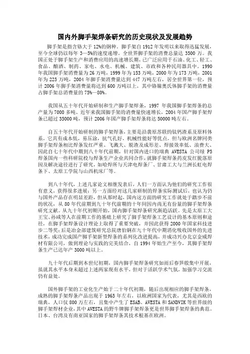
国内外脚手架焊条研究的历史现状及发展趋势脚手架是指含铬大于12%的钢种。
脚手架自1912年发明以来取得迅猛发展,至今全球仍以每年3—5%的速度递增。
全世界脚手架的消费总量达3500万。
我国正处于脚手架生产和消费应用的高速增长期,已广泛应用于石油、化工、轻工、食品、酿酒、制药、家电、水电、机械、建筑、市政和各种民用器具中。
1990年我国脚手架消费量为26万吨,1999年为153万吨,2000年为173万吨,2001年为225万吨,2004年脚手架消费量达到447万吨左右,居全世界第一位,预计2006年脚手架消费量将达到600万吨以上,其中铬镍奥氏体脚手架的消费量占脚手架总消费量的75%—80%。
我国从五十年代开始研制和生产脚手架焊条,1997年我国脚手架焊条的总产量为7000多吨。
近年来我国脚手架的消费量快速增长,2004年国产脚手架焊条已超过35000吨,预计2006年国产脚手架焊条将达50000吨左右。
自五十年代开始研制的脚手架焊条,主要是沿袭原苏联的钛钙渣系及原料体系,它具有成本低,易压涂,抗气孔好,机械性能好等优点,但与欧洲名牌同类脚手架焊条相比焊条发红严重、飞溅大、脱渣及成形差、焊接效率低、浪费大、因此自七十年代中期到八十年代前期,针对国内进口的瑞典AVESTA公司绿P5焊条国内一些科研院校与焊条生产企业共同合作,就脚手架焊条药皮发红脱落原因及解决途径进行了研究,如哈焊所与天津电焊条厂、甘肃工大与兰洲长虹电焊条下、太原工学院与山西机床厂等。
到八十年代,上述几家论文相继发表后,人们一方面认为他们的研究工作很有意义,获得很多进展;另一方面经对这几家研制的焊条实际测试后,也认为仍与国外产品存在明显差距,但从那时起,国内这方面的研究工作就处于踏步不前的状况,从80年代前期到九十年代前期的十年间因内尚无有份量的脚手架焊条研究文献。
从九十年代初期开始,国内脚手架焊条研究渐趋活跃。
先是太原工大王宝、孙咸等人在前期工作的基础上研究了脚手架焊条工艺设计的基本原则和途径,在脚手架焊条设计理论上取得了重要突破,并因此获得2000年国家科技进步二等奖;后是冶金部建筑研究总院唐伯钢在九十年代中期消化吸收国外的先进技术,成功完成国产脚手架新型焊条的系列化改进提高,并成功兴办北京金威焊材有限公司,做到理论与实践的完美结合,自1994年始生产至今,其脚手架焊条生产已达年产3000吨以上。
热处理次数对10Cr9Mo1VNbN焊缝性能影响李晓东【摘要】针对某热电厂600MW超临界机组在基建过程中发生多起10Cr9Mo1VNbN钢材焊缝因焊接质量不合格而挖补返修,并需对挖补位置进行热处理情况,对10Cr9Mo1VNbN焊缝允许的热处理次数进行了研究.通过多次热处理及拉伸、冲击、硬度、金相试验,表明多次热处理对焊缝接头的综合性能没有明显的劣化作用,但处理次数应控制在4次以内.【期刊名称】《吉林电力》【年(卷),期】2014(042)006【总页数】3页(P42-44)【关键词】10Cr9Mo1VNbN;焊缝;热处理;性能【作者】李晓东【作者单位】大唐长山热电厂,吉林松原 131109【正文语种】中文【中图分类】TG457.11;TG156SA335P91是美国橡树岭国家实验室研发的用于电站高温、高压管道的材料,采用微合金控轧和严格控制杂质元素含量的技术,目前已广泛应用于亚临界和超临界火力发电机组主蒸汽管道、再热热段管道及高中压导汽管道,该钢在GB 5310—2008《高压锅炉用无缝钢管》中钢号为10Cr9Mo1VNbN。
在基建过程中,由于焊接质量不合格而经常需要对焊缝进行挖补,并对挖补部位进行热处理。
某热电厂600 MW 超临界机组采用HG-2090/25.4-HM9中间再热超临界直流锅炉,其主蒸汽管道、再热热段管道及连接管均采用10Cr9Mo1VNbN钢材料。
在基建过程中,发生了多起该材质焊缝因焊接质量不合格的挖补返修。
DL/T 869—2004《火力发电厂焊接技术规程》明确规定:焊接接头有超过标准的缺陷时,可采取挖补方式返修,但同一位置上的挖补次数不得超过三次,耐热钢不得超过二次(需要进行热处理的焊接接头,返修后应重做热处理)。
为了保证该材质管道焊缝质量,结合基建过程中的缺陷挖补和焊缝热处理,研究了热处理次数对该材质焊缝组织和性能的影响。
1 10Cr9Mo1VNbN 钢的焊接工艺GB 5310—2008中规定的10Cr9Mo1VNbN 钢化学成分见表1,性能指标见表2。
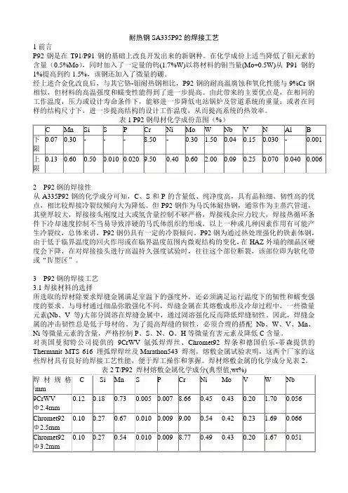
耐热钢SA335P92的焊接工艺1前言P92钢是在T91/P91钢的基础上改良开发出来的新钢种。
在化学成份上适当降低了钼元素的含量(0.5%Mo),同时加入了一定量的钨(1.7%W)以将材料的钼当量(Mo+0.5W)从P91钢的1%提高到约1.5%,该钢还加入了微量的硼。
经上述合金化改良后,与其它铬-钼耐热钢相比,P92钢的耐高温腐蚀和氧化性能与9%Cr钢相似,但材料的高温强度和蠕变性能得到了进一步提高。
由此带来的主要优点是,在相同的工作温度,压力或设计寿命条件下,能够进一步降低电站锅炉及管道系统的重量;或者在同样的结构尺寸下,进一步提高结构的设计工作温度,从而提高系统的热效率。
2P92钢的焊接性从A335P92钢的化学成分可知,C、S和P的含量低、纯净度高,具有晶粒细、韧性高的优点,相比较焊接冷裂纹倾向大为降低。
但P92钢作为马氏体耐热钢,通常作为主蒸汽管道,其壁厚较大,焊接接头刚度过大或氢含量控制不够严格,焊接残余应力较大,焊接热循环条件下冷却速度控制不当易导致淬硬的马氏体组织的形成,以上一种或几种因素作用有可能产生冷裂纹,总体来讲,P92钢仍具有一定的冷裂倾向。
P92钢为通过热处理强化的铁素体钢,由于低于临界温度的回火作用或在临界温度范围内微观结构的变化,在HAZ外端的细晶区硬度会下降,在对焊接接头进行高温持久强度试验时,往往这个部位断裂,该部位即为软化带或“Ⅳ型区”。
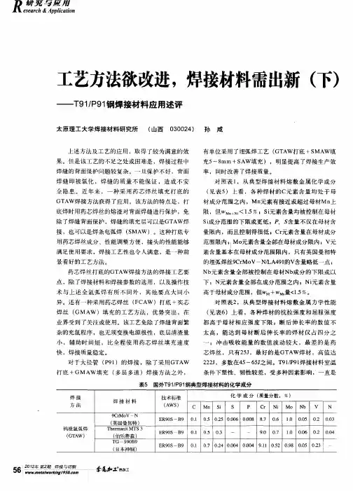
3P92钢的焊接工艺3.1焊接材料的选择所选取的焊材除要求焊缝金属满足室温下的强度外,还必须满足运行温度下的韧性和蠕变强度的要求。
与母材通过细晶弥散强化不同,焊缝金属在其熔敷成形及冷却过程中,一些微量元素(Nb、V等)大部分固溶在焊缝金属中,通过固溶强化反而降低焊缝韧性。
因此,焊缝金属的冲击韧性总是低于母材的。
为了提高焊缝的韧性,必须合理的搭配Nb、W、V、Mn、Ni等微量元素的含量,严格控制P、S、N、O、H等微量有害元素及降低C含量。
182类合金焊接材料产品牌号焊接方法产品数据AWS DIN适用于镍基材料,如600类合金的焊接也常用于镍基材料,不锈钢和低合金钢之间的异种接头的焊接NIMROD 132KS MMA10-03CENiCrFe-1-适用于镍基材料,如600类合金的焊接也常用于镍基材料,不锈钢和低合金钢之间的异种接头的焊接曼彻特焊条,NIMROD 132KS焊条,曼彻特182类焊条,ENiCrFe-1焊条,曼彻特合金焊条,曼彻特NIMROD 132KS焊条,英国曼彻特焊条,182类焊条,英国ENiCrFe-1焊条NIMROD 182KS MMA10-03AENiCrFe-3EL-NiCr15FeMn适用于镍基材料,如600类合金的焊接也常用于镍基材料,不锈钢和低合金钢之间的异种接头的焊接曼彻特焊条,NIMROD 182KS焊条,曼彻特182类焊条,ENiCrFe-3焊条,曼彻特合金焊条,曼彻特NIMROD 182KS焊条,英国曼彻特焊条,182类焊条,英国ENiCrFe-3焊条,NIMROD 182 MMA10-03AENiCrFe-3EL-NiCr15FeMn适用于镍基材料,如600类合金的焊接也常用于镍基材料,不锈钢和低合金钢之间的异种接头的焊接曼彻特焊条,NIMROD 182焊条,曼彻特182类焊条,ENiCrFe-3焊条,曼彻特合金焊条,曼彻特NIMROD 182焊条,英国曼彻特焊条,英国ENiCrFe-3焊条NIMAX 182 MMA10-03BENiCrFe-3EL-NiCr15FeMn适用于镍基材料,如600类合金的焊接也常用于镍基材料,不锈钢和低合金钢之间的异种接头的焊接曼彻特焊条,NIMAX 182焊条,曼彻特182类焊条,ENiCrFe-3焊条,曼彻特合金焊条,曼彻特NIMAX 182焊条,英国曼彻特焊条,182类焊条,英国ENiCrFe-3焊条NIMROD NC19Nb MMA 10 -EL-NiCr19Nb适用于镍基材料,如600类合金的焊接也常用于镍基材料,不锈钢和低合金钢之间的异种接头的焊接曼彻特焊条,NIMROD NC19Nb焊条,曼彻特182类焊条,曼彻特合金焊条,曼彻特NIMROD NC19Nb焊条,英国曼彻特焊条,182类焊条,20.70.Nb TIG/MIG/SA15-06AERNiCr3SG-NiCr20Nb适用于镍基材料,如600类合金的焊接也常用于镍基材料,不锈钢和低合金钢之间的异种接头的焊接曼彻特焊丝,20.70.Nb焊丝,曼彻特182类焊丝,ERNiCr3焊丝,曼彻特合金焊丝,曼彻特20.70.Nb焊丝,英国曼彻特焊丝,182类焊丝,英国ERNiCr3焊丝NiCr Flux 17-06C -适用于镍基材料,如600类合金的焊接也常用于镍基材料,不锈钢和低合金钢之间的异种接头的焊接曼彻特焊条,NiCr焊条,曼彻特182类焊条,曼彻特合金焊条,曼彻特NiCr焊条,英国曼彻特焊条,182类焊条,英国NiCr焊条AB类合金焊接材料NIMROD AKS MMA10-04AENiCrFe-2EL-NiCr15MoNb使用范围与182类焊材相似与182类焊材相比,其焊缝在600°C以上具有更好的高温性能曼彻特焊条,NIMROD AKS焊条,曼彻特AB类焊条,ENiCrFe-2焊条,曼彻特合金焊条,曼彻特NIMROD AKS焊条,英国曼彻特焊条,AB类焊条,英国ENiCrFe-2焊条NIMROD AB MMA10-04AENiCrFe-2/4EL-NiCr15MoNb使用范围与182类焊材相似与182类焊材相比,其焊缝在600°C以上具有更好的高温性能曼彻特焊条,NIMROD AB焊条,曼彻特AB类焊条,ENiCrFe-2/4焊条,曼彻特合金焊条,曼彻特NIMROD AB焊条,英国曼彻特焊条,AB类焊条,英国ENiCrFe-2/4焊条NIMAX A MMA 10-04BENiCrFe-2EL-NiCr15MoNb使用范围与182类焊材相似与182类焊材相比,其焊缝在600°C以上具有更好的高温性能曼彻特焊条,NIMAX A焊条,曼彻特AB类焊条,ENiCrFe-2焊条,曼彻特合金焊条,曼彻特NIMAX A焊条,英国曼彻特焊条,AB类焊条,英国ENiCrFe-2焊条20.70.Nb TIG/MIG/SA15-06AERNiCr-3SG-NiCr20Nb使用范围与182类焊材相似与182类焊材相比,其焊缝在600°C以上具有更好的高温性能曼彻特焊丝,NIMAX A焊丝,曼彻特AB类焊丝,ERNiCr-3焊丝,曼彻特合金焊丝,曼彻特NIMAX A焊丝,英国曼彻特焊丝,AB类焊丝,英国ERNiCr-3焊丝NiCr Flux 17-06C- -使用范围与182类焊材相似与182类焊材相比,其焊缝在600°C以上具有更好的高温性能曼彻特焊条,NiCr焊条,曼彻特AB类焊条,曼彻特合金焊条,曼彻特NiCr焊条,英国曼彻特焊条,AB类焊条,英国NiCr焊条625类合金焊接材料NIMROD 625KS MMA10-05AENiCrMo-3EL-NiCr20Mo9Nb焊缝金属具有优良的综合机械性能和耐腐蚀性能适用于相应的625类合金同时也适用于其他高温合金,如601,800等合金721类焊材适用于6%Mo,825及28合金的焊接曼彻特焊条,NIMROD 625KS焊条,曼彻特625类焊条,ENiCrMo-3焊条,曼彻特合金焊条,曼彻特NIMROD 625KS焊条,英国曼彻特焊条,625类焊条,英国ENiCrMo-3焊条NIMROD 625 MMA10-05AENiCrMo-3EL-NiCr20Mo9Nb焊缝金属具有优良的综合机械性能和耐腐蚀性能适用于相应的625类合金同时也适用于其他高温合金,如601,800等合金721类焊材适用于6%Mo,825及28合金的焊接曼彻特焊条,NIMROD 625焊条,曼彻特625类焊条,ENiCrMo-3焊条,曼彻特合金焊条,曼彻特NIMROD 625焊条,英国曼彻特焊条,625类焊条,英国ENiCrMo-3焊条62-50 TIG/MIG/SA15-06BERNiCrMo-3SG-NiCr21Mo9Nb焊缝金属具有优良的综合机械性能和耐腐蚀性能适用于相应的625类合金同时也适用于其他高温合金,如601,800等合金721类焊材适用于6%Mo,825及28合金的焊接曼彻特焊丝,62-50焊丝,曼彻特625类焊丝,ERNiCrMo-3焊丝,曼彻特合金焊丝,曼彻特62-50焊丝,英国曼彻特焊丝,625类焊丝,英国ERNiCrMo-3焊丝NIMROD 721KS MMA10-05E- -焊缝金属具有优良的综合机械性能和耐腐蚀性能适用于相应的625类合金同时也适用于其他高温合金,如601,800等合金721类焊材适用于6%Mo,825及28合金的焊接曼彻特焊条,NIMROD 721KS焊条,曼彻特625类焊条,曼彻特合金焊条,曼彻特NIMROD 721KS焊条,英国曼彻特焊条,625类焊条,英国NIMROD 721KS焊条72-10 TIG/MIG/SA15-06N- -焊缝金属具有优良的综合机械性能和耐腐蚀性能适用于相应的625类合金同时也适用于其他高温合金,如601,800等合金721类焊材适用于6%Mo,825及28合金的焊接72-10焊条,曼彻特625类焊条,曼彻特合金焊条,曼彻特72-10焊条,英国曼彻特焊条,625类焊条,英国72-10焊条C类合金焊接材料NIMROD C276 MMA10-07A1ENiCrMo-4EL-NiMo15Cr15EW适用于大多数腐蚀环境含22%Cr的59合金具有优良的耐腐蚀性能NIMROD C和C焊条主要用于堆焊,如热作模具的堆焊等KS型焊条特别适合固定位置管道的焊接曼彻特焊条,NIMROD C276焊条,曼彻特C类焊条,ENiCrMo-4焊条,曼彻特合金焊条,曼彻特NIMROD C276焊条,英国曼彻特焊条,C类焊条,英国ENiCrMo-4焊条NIMROD C276KS MMA10-07A2ENiCrMo-4EL-NiMo15Cr15W适用于大多数腐蚀环境含22%Cr的59合金具有优良的耐腐蚀性能NIMROD C和C焊条主要用于堆焊,如热作模具的堆焊等KS型焊条特别适合固定位置管道的焊接曼彻特焊条,NIMROD C276KS焊条,曼彻特C类焊条,ENiCrMo-4焊条,曼彻特合金焊条,曼彻特NIMROD C276KS焊条,英国曼彻特焊条,C类焊条,英国ENiCrMo-4焊条HAS C276 TIG 15-06EERNiCrMo-4SG-NiMo16Cr16W适用于大多数腐蚀环境含22%Cr的59合金具有优良的耐腐蚀性能NIMROD C和C焊条主要用于堆焊,如热作模具的堆焊等KS型焊条特别适合固定位置管道的焊接HAS C276焊丝,曼彻特C类焊丝,ERNiCrMo-4焊丝,曼彻特合金焊丝,曼彻特HAS C276焊丝,英国曼彻特焊丝,C类焊丝,英国ERNiCrMo-4焊丝NIMROD C4KS MMA10-07CENiCrMo-7EL-NiMo15Cr15Ti适用于大多数腐蚀环境含22%Cr的59合金具有优良的耐腐蚀性能NIMROD C和C焊条主要用于堆焊,如热作模具的堆焊等KS型焊条特别适合固定位置管道的焊接曼彻特焊条,NIMROD C4KS焊条,曼彻特C类焊条,ENiCrMo-7焊条,曼彻特合金焊条,曼彻特NIMROD C4KS焊条,英国曼彻特焊条,C类焊条,英国ENiCrMo-7焊条HAS C4 TIG 15-06HERNiCrMo-7SG-NiMo16Cr16Ti适用于大多数腐蚀环境含22%Cr的59合金具有优良的耐腐蚀性能NIMROD C和C焊条主要用于堆焊,如热作模具的堆焊等KS型焊条特别适合固定位置管道的焊接HAS C4焊丝,曼彻特C类焊丝,ERNiCrMo-7焊丝,曼彻特合金焊丝,曼彻特HAS C4焊丝,英国曼彻特焊丝,C类焊丝,英国ERNiCrMo-7焊丝NIMROD 59KS MMA10-07FENiCrMo-13EL-NiCr22Mo16适用于大多数腐蚀环境含22%Cr的59合金具有优良的耐腐蚀性能NIMROD C和C焊条主要用于堆焊,如热作模具的堆焊等KS型焊条特别适合固定位置管道的焊接曼彻特焊条,NIMROD 59KS焊条,曼彻特C类焊条,ENiCrMo-13焊条,曼彻特合金焊条,曼彻特NIMROD 59KS焊条,英国曼彻特焊条,C类焊条,英国ENiCrMo-13焊条HAS 59 TIG 15-06JERNiCrMo-13SG-Ni23Mo16适用于大多数腐蚀环境含22%Cr的59合金具有优良的耐腐蚀性能NIMROD C和C焊条主要用于堆焊,如热作模具的堆焊等KS型焊条特别适合固定位置管道的焊接HAS 59焊丝,曼彻特C类焊丝,ERNiCrMo-1焊丝,曼彻特合金焊丝,曼彻特HAS 59焊丝,英国曼彻特焊丝,C类焊丝,英国ERNiCrMo-1焊丝NIMROD C MMA 10ENiCrMo-5SG-Ni23Mo16适用于大多数腐蚀环境含22%Cr的59合金具有优良的耐腐蚀性能NIMROD C和C焊条主要用于堆焊,如热作模具的堆焊等KS型焊条特别适合固定位置管道的焊接曼彻特焊条,NIMROD C焊条,曼彻特C类焊条,ENiCrMo-5焊条,曼彻特合金焊条,曼彻特NIMROD C焊条,英国曼彻特焊条,C类焊条,英国ENiCrMo-5焊条Cr-Mo耐热焊接材料焊条类别品名AWS型号焊缝金属化学成份(wt %)全焊缝金属机械性能特征与用途C Mn Si S P Cr Mo Cu Sn As Sb 抗拉0.2%Akv冲强度屈服强度击功焊条Chromet 1 E9015-B9 0.07 0.8 0.3 0.012 0.015 1.25 0.55 <0.10 650 570 160手工电弧焊条,满足AWS/ASME和BSEN标准,适用于大多数电站设备的建造曼彻特焊条,Chromet 1焊条,曼彻特Cr-Mo焊条,E9015-B9焊条,曼彻特合金焊条,曼彻特Chromet 1焊条,英国曼彻特焊条,Cr-Mo焊条,英国E9015-B9焊条Chromet1L E7015-B2 0.04 0.8 0.3 0.012 0.015 1.25 0.55 0.05 600 500 180焊缝金属硬度和焊接残余应力较低,具有优良的抗硫化物应力腐蚀开裂的性能,也适用于焊后不进行热处理的薄截面结构的焊接曼彻特焊条,Chromet1L焊条,曼彻特Cr-Mo焊条,E7015-B2焊条,曼彻特合金焊条,曼彻特Chromet1L焊条,英国曼彻特焊条,Cr-Mo焊条,英国E7015-B2焊条Chromet1XE8018-B2 0.04 0.8 0.3 0.012 0.015 1.25 0.55 <0.05 0.002 0.003 <0.002 660 570 160严格控制残余有害元素,确保熔敷金属具有低的X和J脆化指数,在400-600℃的工作温度下具有优良的抗回火脆化性能曼彻特焊条,Chromet 1X焊条,曼彻特Cr-Mo焊条,E8018-B2焊条,曼彻特合金焊条,曼彻特Chromet 1X焊条,英国曼彻特焊条,Cr-Mo焊条,英国E8018-B2焊条实芯焊丝类别品名AWS型号焊丝化学成份全焊缝金属机械性能特征与用途C Mn Si S P Cr Ni Mo Cu抗拉强度0.2%屈服强度Akv冲击功实芯焊丝1CrMo ER80S-G 0.1 1 0.6 0.010 0.015 8.7 <0.1 0.5 0.1 590 480 >115表面镀铜的钢GTAW和GMAW实芯焊丝;成份按欧洲BSEN标准定制曼彻特焊丝1CrMo焊丝,曼彻特实芯焊丝,ER80S-G焊丝,曼彻特合金焊丝,曼彻特1CrMo焊丝,英国曼彻特焊丝,英国ER80S-G焊丝,实芯焊丝ER80S-B2 ER80S-B2 0.1 0.5 0.5 0.010 0.015 1.3 <0.1 0.5 0.1 590 480 >115表面镀铜的钢TIG和MIG实芯焊丝,成份按美国AWS/ASME标准定制曼彻特焊丝ER80S-B2焊丝,曼彻特实芯焊丝,ER80S-B2焊丝,曼彻特合金焊丝,曼彻特ER80S-B2焊丝,英国曼彻特焊丝,英国EER80S-B2焊丝,实芯焊丝药芯焊丝类别品名AWS型号焊缝金属化学成份全焊缝金属化学成份特征与用途C Mn Si S P Cr Mo Cu抗拉强度0.2%屈服强度Akv冲击功药芯焊丝Cormet1 E81t1-b2m 0.06 1.0 0.3 0.01 0.01 1.3 0.55 0.05 650 550 >40采用高质量超低杂质合金带钢制造,熔敷效率相对焊丝重量为90%曼彻特焊丝Cormet1焊丝,曼彻特药芯焊丝,E81t1-b2m焊丝,曼彻特合金焊丝,曼彻特Cormet1焊丝,英国曼彻特焊丝,英国E81t1-b2m焊丝,药芯焊丝焊丝和焊剂类别品名AWS型号焊丝及焊缝化学成份(wt %)全焊缝金属机械性能特征与用途C Mn Si S P Cr Mo抗拉强度0.2%屈服强Akv冲击功度焊丝和焊剂1CrMoLA121F9P0-EB2B20.07 0.8 0.25 0.010 0.015 1.2 0.55 480 360 80LA121为碱性氟化物高碱度烧结焊剂,具有中性焊缝Mn和Si成份过渡特性,焊剂颗粒尺寸范围为0.2-2.0mm曼彻特焊丝1CrMo焊丝,曼彻特1CrMo焊丝,F9P0-EB2B2焊丝,曼彻特合金焊丝,曼彻特LA121焊丝,英国曼彻特焊丝,英国F9P0-EB2B2焊丝,LA121焊丝,1CrMoLA121焊丝,焊剂WB36钢焊接材料焊条类别品名AWS型号焊缝金属化学成分(wt %)全焊缝金属机械性能特征与用途C Mn Si S P Cr Ni Mo Cu抗拉强度0.2%屈服强度Akv冲击功焊条1NiMo.B E9018-G 0.10 1.2 0.3 0.010 0.015 0.1 0.9 0.35 0.05 900 630 45℃碱性低氢型焊条,采用高纯度低碳钢钢芯和特殊抗潮粘结晶剂制造,具有超低焊缝扩散氢含量曼彻特焊条,1NiMo.B焊条,曼彻特1NiMo.B焊条,E9018-G焊条,曼彻特合金焊条,曼彻特E9018-G焊条,英国曼彻特焊条,E9018-G焊条,英国E9018-G焊条焊丝类别品名AWS型号焊丝化学成份(wt %)全焊缝金属机械性能特征与用途C Mn Si S P Ni Mo Cu抗拉强度0.2%屈服强度Akv冲击功焊丝MnMo ER80S-D2 0.1 1.9 0.6 0.005 0.01 0.05 0.5 0.1 605 490 >100℃表面镀铜的GTAW和GMAW焊实芯焊丝曼彻特焊丝,MnMo焊丝,曼彻特MnMo焊丝,ER80S-D2焊丝,曼彻特合金焊丝,曼彻特ER80S-D2焊丝,英国曼彻特焊丝,英国ER80S-D2焊丝焊剂和焊丝类别品名AWS型号焊缝金属化学成分(wt %)全焊缝金属机械性能特征与用途C Mn Si S P Cr Ni Mo Cu 抗拉0.2%Akv强度屈服强度冲击功焊丝和焊剂1NiMoLA121EF3 0.10 1.75 0.2 0.01 0.01 0.05 0.9 0.5 0.1 680 580 70与1NiMo焊丝配用的焊剂,为碱性氟化物高碱度烧结焊剂,具有中性焊缝Mn和Si成份补偿特性;焊剂颗粒尺寸范围为0.2-2.0mm曼彻特焊丝1NiMo LA121焊丝,曼彻特1NiMo LA121焊丝,EF3焊丝,曼彻特合金焊丝,曼彻特EF3焊丝,英国曼彻特焊丝,英国EF3焊丝,1NiMo LA121焊丝,1NiMo LA121焊剂0.5%Mo耐热钢焊接材料别品名AWS型号焊缝金属化学成分(wt %) 全焊缝金属机械性能特征与用作C Mn Si S P Cr Ni Mo Cu抗拉强度(MPa)0.2%屈服强度(MPa)Akv冲击功(%)焊条MO.B E70198-Al 0.1 0.8 0.3 0.01 0.15 0.05 0.05 0.55 0.05 590 480 100℃碱性低氢型焊条,采用高纯度低碳钢钢芯和特殊抗潮粘结剂制造,具有超低焊缝扩散氢含量曼彻特焊条,MO.B焊条,曼彻特MO.B焊条,E70198-Al焊条,曼彻特合金焊条,曼彻特E70198-Al 焊条,英国曼彻特焊条,E70198-Al焊条CMo ER70S-Al 0.1 1.2 0.6 0.01 0.01 0.03 0.02 0.5 0.05 620 505 96℃表面镀铜的GTAW和GMAW焊实芯焊丝曼彻特焊丝,CMo焊丝,曼彻特CMo焊丝,ER70S-Al焊丝,曼彻特合金焊丝,曼彻特ER70S-Al焊丝,英国曼彻特焊丝,ER70S-Al焊丝,英国CMo焊丝,实芯焊丝CrMoV耐热钢焊接材料焊条类别品名AWS型号焊缝金属化学成份金属机械性能特征与用途C Mn Si S P Cr Mo V Ni抗拉强度0.2%屈服强度Akv冲击功焊条Chromet1V EcrMoV1b32 0.08 0.85 0.3 0.012 0.012 1.2 1.10 0.20 800 745 60手工电弧焊条,满足BSEN和DIN的相应标准曼彻特焊条,Chromet1V焊条,曼彻特Chromet1V焊条,EcrMoV1b32焊条,曼彻特合金焊条,曼彻特EcrMoV1b32焊条,英国曼彻特焊条,EcrMoV1b32焊条,英国Chromet1V焊条,英国手工焊条13CMVEcrMoV1B32 0.13 0.6 0.3 0.012 0.012 1.2 1.05 0.25 0.0513CMV焊条的成份与Chromet1V的相似,但含有较高的碳和钒,13CMV还可根据用户要求,按GE标准B50A273定制曼彻特焊条,13CMV焊条,曼彻特13CMV焊条,EcrMoV1B32焊条,曼彻特合金焊条,曼彻特EcrMoV1B32焊条,英国曼彻特焊条,EcrMoV1B32焊条,英国13CMV焊条,英国手工焊条药芯焊丝类别品名AWS型号焊缝金属化学成份金属机械性能特征与用途C Mn Si S P Cr Mo V抗拉强度0.2%屈服强度Akv冲击功药芯焊丝Cormet1V0.06 1 0.4 0.01 0.01 1.3 1.1 0.2 650 550 50Cormet 1V为全位置药芯焊丝,采用高质量超低杂质合金带钢制造,熔敷效率相对焊丝重量为90%曼彻特焊丝,Cormet 1V焊丝,曼彻特1Cormet 1V焊丝,曼彻特合金焊丝,英国曼彻特焊丝,Cormet1V焊丝,英国Cormet 1V焊丝,曼彻特药芯焊丝12CrMoV耐热钢焊接材料焊条类别品名AWS型号焊缝金属化学成份金属机械性能特性用途C Mn Si S P Cr Ni Mo W V抗拉强度0.2%屈服强度Akv冲击功焊条Chromet12MVECrMoWV12B 320.20 0.8 0.25 0.010 0.017 11 0.5 1 0.5 0.3 750 550 40碱性低氢型的全位置焊条,采用特殊抗潮粘结剂制造,具有超低焊缝扩散氢含量曼彻特焊条,Chromet 12MV焊条,曼彻特Chromet 12MV焊条,ECrMoWV 12B 32焊条,曼彻特合金焊条,曼彻特ECrMoWV 12B 32焊条,英国曼彻特焊条,ECrMoWV 12B 32焊条,英国Chromet 12MV焊条,12CrMoV 焊条实芯焊丝类品名AWS型号焊缝金属化学成份金属机械性能特性用途别C Mn Si S P Cr Ni Mo V W 抗拉强度0.2%屈服强度Akv冲击功实芯焊丝12CrMoVWCrMoWV12Si0.2 0.6 0.4 0.005 0.01 11 0.6 1 0.3 0.5 750 600 50 实芯GTAW焊丝曼彻特焊丝,12CrMoV焊丝,曼彻特12CrMoV焊丝,W CrMoWV12Si焊丝,曼彻特合金焊丝,曼彻特W CrMoWV12Si焊丝,英国曼彻特焊丝,W CrMoWV12Si焊丝,英国12CrMoV焊丝,实芯焊丝E911耐热钢焊接材料焊条类别品名AWS型号焊缝金属化学成份金属机械性能特征与用途C Mn Si S P Cr Ni Mo W Nb V N Al抗拉强度0.2%屈服强度Akv冲击功焊条Chromet10MW0.1 0.8 0.25 0.008 0.01 9.5 0.5 1.0 1.0 0.05 0.22 0.05 0.01 760 620 60碱性低氢型的全位置焊条,采用特殊抗潮粘结剂制造,具有超低焊缝扩散氢含量曼彻特焊条,Chromet 10MW焊条,曼彻特Chromet 10MW焊条,曼彻特合金焊条,英国曼彻特焊条,Chromet 10MW焊条,英国Chromet 10MW焊条T92/P92钢焊接材料焊条类别品名AWS型号焊缝金属化学成份金属机械性能特性与用途C Mn Si S P Cr Ni Mo W Nb V N B Al Cu抗拉强度0.2%屈服强度Akv冲击功焊条Chromet920.11 0.6 0.25 0.01 0.01 9.0 0.6 0.45 1.7 0.05 0.20 0.05 0.003 <0.01 <0.05 740 630 60焊条的熔敷效率相对焊芯重量为120% 曼彻特焊条,Chromet 92焊条,曼彻特Chromet 92焊条,曼彻特合金焊条,英国曼彻特焊条,Chromet 92焊条,英国Chromet 92焊条实芯焊丝类别品名AWS型号焊缝金属化学成份金属机械性能特性与用途C Mn Si S P Cr Ni Mo W Nb V N B Al Cu抗拉强度0.2%屈服强度Akv冲击功实芯焊丝9CrWV 0.11 0.7 0.30 0.01 0.01 9 0.5 0.45 1.7 0.06 0.2 0.05 0.003 <0.01 <0.05 800 700 220表面不镀铜的GTAW和埋弧焊实芯焊丝曼彻特焊丝,9CrWV焊丝,曼彻特9CrWV焊丝,曼彻特合金焊丝,英国曼彻特焊丝,9CrWV焊丝,英国9CrWV焊丝,实芯焊丝,埋弧焊丝药芯焊丝类别品名AWS型号焊缝金属化学成份金属机械性能特性与用途C Mn Si S P Cr Ni Mo W Nb V N B Al Cu抗拉强度0.2%屈服强度Akv冲击功药芯SupercoreF920.11 0.8 0.30 0.01 0.017 9 0.5 0.45 1.7 0.04 0.2 0.04 0.003 <0.01 <0.05 775 650 25用于P92钢的全位置药芯焊丝,采用高焊丝质量超低杂质合金带钢制造,熔敷效率相对焊丝重量为90%曼彻特焊丝,Supercore F92焊丝,曼彻特Supercore F92焊丝,曼彻特合金焊丝,英国曼彻特焊丝,Supercore F92焊丝,英国Supercore F92焊丝,药芯焊丝焊丝和焊剂类别品名AWS型号焊缝金属化学成份金属机械性能特性与用途C Mn Si S P Cr Ni Mo W Nb V N B抗拉强度0.2%屈服强度Akv冲击功焊丝焊剂9CrWVLA4910.09 0.7 0.3 0.01 0.01 8.5 0.5 0.4 1.7 0.04 0.16 0.04 0.001 740 630 40与9CrWV配用的焊剂,为碱性氟化物烧结焊剂曼彻特焊丝/焊剂9CrWVLA491焊丝/焊剂,曼彻特9CrWVLA491焊丝/焊剂,曼彻特合金焊丝/焊剂,英国曼彻特焊丝/焊剂,9Cr1Mo(P91/T91)钢焊接材料焊条,类别品名AWS型号焊缝金属化学成份金属机械性能特征与用途C Mn Si S P Cr Ni Mo Nb V N Cu Sn抗拉强度0.2%屈服强度Akv冲击功焊条Chromet9MV-NE9015-B9 0.10 0.7 0.25 0.008 0.008 9.0 0.7 1.0 0.05 0.2 0.05 0.05 0.003 770 640 65标准P91/T91钢手工电弧焊条,高含镍,具有最佳焊缝韧性曼彻特焊条,Chromet 9MV-N焊条,曼彻特Chromet 9MV-N焊条,E9015-B9焊条,曼彻特合金焊条,曼彻特E9015-B9焊条,英国曼彻特焊条,E9015-B9焊条,英国Chromet 9MV-N焊条,英国手工焊条Chromet9-B9 E9015-B9 0.1 0.5 0.25 0.008 0.008 9 0.3 1 0.04 0.2 0.05 0.05 710 590 75手工电弧焊条,满足AWS/ASMEA5.5E9015-B9标准曼彻特焊条,Chromet9-B9焊条,曼彻特Chromet9-B9焊条,E9015-B9焊条,曼彻特合金焊条,曼彻特E9015-B9焊条,英国曼彻特焊条,E9015-B9焊条,英国Chromet9-B9焊条,手工焊条Chromet91VNR E9016-B9 0.1 0.7 0.25 0.008 0.008 9.0 0.7 1.0 0.05 0.20 0.05 0.05 0.003 620 530 47手工电弧焊条,专门用于P91钢打底焊接,不需背面吹氩保护曼彻特焊条,Chromet91VNR焊条,曼彻特Chromet91VNR焊条,E9016-B9焊条,曼彻特合金焊条,曼彻特E9016-B9焊条,英国曼彻特焊条,E9016-B9焊条,英国Chromet91VNR焊条,手工焊条实芯焊丝类别品名AWS型号焊缝金属化学成份金属机械性能特征与用途C Mn Si S P Cr Ni Mo Nb V N Cu Al抗拉强度0.2%屈服强度Akv冲击功实芯焊丝9CrMoV-N EB9 0.1 0.5 0.25 0.006 0.008 8.7 0.6 1 0.05 0.2 0.03 0.03 <0.01 800 700 220表面不镀铜的GTAW,GMAW和埋弧焊实芯焊丝曼彻特焊丝,9CrMoV-N焊丝,曼彻特9CrMoV-N焊丝,EB9焊丝,曼彻特合金焊丝,曼彻特EB9焊丝,英国曼彻特焊丝,EB9焊丝,英国9CrMoV-N焊丝,实芯焊丝药芯焊丝类别品名AWS型号焊缝金属化学成份金属机械性能特征与用途C Mn Si S P Cr Ni Mo Nb V N Cu Al抗拉强度0.2%屈服强度Akv冲击功药芯焊丝SupercoreF910E9015-B9 0.10 0.8 0.25 0.010 0.016 9.0 0.5 1.0 0.04 0.20 0.05 0.05 0.01 790 660 25用于P91钢的全位置药芯焊丝,采用高质量超低杂质合金带钢制造,熔敷效率相对焊丝重量为90%曼彻特焊丝,Supercore F910焊丝,曼彻特Supercore F910焊丝,E9015-B9焊丝,曼彻特合金焊丝,曼彻特E9015-B9焊丝,英国曼彻特焊丝,E9015-B9焊丝,英国Supercore F910焊丝,药芯焊丝金属芯焊丝类别品名AWS型号焊缝金属化学成份金属机械性能特征与用途C Mn Si S P Cr Ni Mo Nb V N Cu Al 抗拉0.2%Akv强度屈服强度冲击功金属芯焊丝CormetM91E90C-G(B9) 0.1 1.0 0.3 0.01 0.01 9.0 0.3 1.0 0.05 0.20 0.05 0.05 0.03 780 650 25用于GMAW焊的金属芯焊丝,采用高纯度带钢制造,熔敷效率相对焊丝重量为96%曼彻特Cormet M91焊丝,E90C-G(B9)焊丝,曼彻特合金焊丝,曼彻特E90C-G(B9)焊丝,英国曼彻特焊丝,E90C-G(B9)焊丝,英国Cormet M91焊丝,英国金属芯焊丝焊丝和焊剂类别品名AWS型号焊缝金属化学成份金属机械性能特征与用途C Mn Si S P Cr Ni Mo Nb V N抗拉强度0.2%屈服强度Akv冲击功焊丝和焊剂9CrMoV-NLA491EB9 0.08 0.60.320.005 0.007 8.6 0.6 1 0.05 0.17 0.05 750 630 45实芯T91/P91钢埋弧焊丝,9CrMoV-N配用的焊剂,与为碱性氟化物烧结焊剂曼彻特焊丝/焊剂,9CrMoV-NLA491焊丝/焊剂,曼彻特9CrMoV-NLA491焊丝/焊剂,曼彻特合金焊丝/焊剂,英国曼彻特焊丝/焊剂,9Cr1Mo焊接材料,EB9焊丝/焊剂9CrMo耐热钢焊接材料焊条类别品名AWS型号焊缝金属化学成份金属机械性能特性与用途C Mn Si S P Cr Ni Mo Cu抗拉强度0.2%屈服强度Akv冲击功焊条Chromet9 E8015-B8 0.06 0.75 0.3 0.012 0.015 9 0.2 1 <0.05 680 550 130碱性低氢型的全位置焊条,采用特殊抗潮粘结剂制造,具有超低焊缝扩散氢含量曼彻特焊条,Chromet9焊条,曼彻特Chromet9焊条,E8015-B8焊条,曼彻特合金焊条,曼彻特E8015-B8焊条,英国曼彻特焊条,E8015-B8焊条,英国Chromet9焊条实芯焊丝类别品名AWS型号焊缝金属化学成份金属机械性能特性与用途C Mn Si S P Cr Ni Mo Cu抗拉强度0.2%屈服强度Akv冲击功实芯焊丝9CrMo ER80S-B8 0.07 0.5 0.3 0.01 0.015 9 0.1 0.9 0.1 729 612 80表面镀铜的9Cr-1Mo钢GTAW和GMAW实芯焊丝曼彻特焊丝,9CrMo焊丝,曼彻特9CrMo焊丝,ER80S-B8焊丝,曼彻特合金焊丝,曼彻特ER80S-B8焊丝,英国曼彻特焊丝,ER80S-B8焊丝,英国9CrMo焊丝,曼彻特实芯焊丝药芯焊丝类别品名AWS型号焊缝金属化学成份金属机械性能特性与用途C Mn Si S P Cr Mo Cu Ni抗拉强度0.2%屈服强度Akv冲击功药芯焊丝Cormet9E505T1-4 0.06 0.8 0.3 0.01 0.01 9 1.0 0.05 0.3 640 5009Cr-1Mo钢全位置药芯焊丝,采用高质量超低杂质合金带钢制造,熔敷效率相对焊丝重量为90% 曼彻特焊丝,Cormet 9焊丝,曼彻特Cormet 9焊丝,E505T1-4焊丝,曼彻特合金焊丝,曼彻特E505T1-4焊丝,英国曼彻特焊丝,E505T1-4焊丝,英国Cormet 9焊丝,药芯焊丝5CrMo耐热钢焊接材料焊条类别品名AWS型号焊缝金属化学成份金属机械性能特性与用途C Mn Si S P Cr Ni Mo Cu抗拉强度0.2%屈服强度Akv冲击功焊条Chromet5 E8015-B6 0.06 0.8 0.3 0.01 0.015 5 0.2 0.55 0.05 540 360 140焊条的熔敷效率相对焊芯重量为120%,相对整个焊条重量为65%英曼彻特焊条,Chromet5焊条,曼彻特Chromet5焊条,E8015-B6焊条,曼彻特合金焊条,曼彻特E8015-B6焊条,英国曼彻特焊条,E8015-B6焊条,英国Chromet5焊条实芯焊丝类别品名AWS型号焊丝化学成份金属机械性能特性与用途C Mn Si S P Cr Ni Mo Cu V抗拉强度0.2%屈服强度Akv冲击功实芯焊丝5CrMo ER90S-B6 0.07 0.5 0.4 0.01 0.01 5.7 0.1 0.55 0.2 0.02 660 560 240表面镀铜5Cr-0.5Mo钢GTAW和GMAW实芯焊丝曼彻特焊丝,5CrMo焊丝,曼彻特5CrMo焊丝,ER90S-B6焊丝,曼彻特合金焊丝,曼彻特ER90S-B6焊丝,英国曼彻特焊丝,ER90S-B6焊丝,英国5CrMo焊丝,实芯焊丝药芯焊丝类别品名AWS型号焊缝化学成份金属机械性能特性与用途C Mn Si S P Cr Mo Cu Ni抗拉强度0.2%屈服强度Akv冲击功曼彻特焊丝,Cormet5焊丝,曼彻特Cormet5焊丝,E81T1-B6M焊丝,曼彻特合金焊丝,曼彻特E81T1-B6M焊丝,英国曼彻特焊丝,E81T1-B6M焊丝,英国Cormet5焊丝,药芯焊丝药芯焊丝Cormet5 E81T1-B6M 0.06 0.8 0.3 0.01 0.01 5 0.5 0.05 0.01 640 520 555Cr-0.5Mo钢全位置药芯焊丝,采用高质量超低杂质合金带钢制造,熔敷效率相对焊丝重量为90%T23/P23耐热钢焊接材料焊条类别品名AWS型号焊缝金属化学成份金属机械性能特征与用途C Mn Si S P Cr Ni Mo W Nb V N B抗拉强度0.2%屈服强度Akv冲击功焊条Chromet23L0.05 0.5 0.25 0.01 0.01 2.2 0.6 0.2 1.6 0.03 0.23 0.02 0.001 940 870 22焊条的熔敷效率相对焊芯重量为120%,相对整个焊条重量为65%曼彻特焊条,Chromet 23L焊条,曼彻特Chromet 23L焊条,Chromet 23L焊条,曼彻特合金焊条,英国曼彻特焊条,英国Chromet 23L焊条实芯焊丝类别品名AWS型号焊缝金属化学成份金属机械性能特征与用途C Mn Si S P Cr Ni Mo W Nb V B Al抗拉强度0.2%屈服强度Akv冲击功实芯焊丝2CrWV ER90S-G 0.06 0.6 0.3 0.010 0.010 2.4 0.5 0.2 1.6 0.05 0.25 0.003 0.01 755 700 190表面镀铜的T23/P23钢实芯GTAW焊丝曼彻特焊丝,2CrWV焊丝,曼彻特2CrWV焊丝,ER90S-G焊丝,曼彻特合金焊丝,曼彻特ER90S-G焊丝,英国曼彻特焊丝,ER90S-G焊丝,英国2CrWV焊丝,实芯焊丝焊丝和焊剂类别品名AWS型号焊缝金属化学成份金属机械性能特征与用途C Mn Si S P Cr Ni Mo W Nb V B抗拉强度0.2%屈服强度Akv冲击功焊丝和焊剂2CrWVLA4910.05 0.6 0.35 0.006 0.01 2.2 0.5 0.1 1.5 0.05 0.22 0.002 650 570 175表面镀铜的实芯T23/P23耐热钢埋弧焊丝,与2CrWV焊丝配用的焊剂,为碱性氟化物烧结焊剂曼彻特焊丝/焊剂,2CrWVLA491焊丝/焊剂,曼彻特2CrWVLA491焊丝/焊剂,曼彻特合金焊丝/焊剂,英国曼彻特焊丝/焊剂,21/4Cr-Mo焊接材料21/4Cr-Mo耐热钢焊接材料焊条类品名AWS型号焊缝金属化学成份(wt %)全焊缝金属机械性能特征与用途别C Mn Si S P Cr Mo Cu Sn As Sb 抗拉强度0.2%屈服强度Akv冲击功焊条Chroment2 E9018-b3 0.07 0.8 0.3 0.012 0.015 2.25 1.05 <0.10 <0.006 <0.010 700 620 140手工电弧焊条,满足AWS/ASME和BSEN标准,适用于大多数电站设备的建造曼彻特焊条,Chroment2焊条,曼彻特Chroment2焊条,E9018-b3焊条,曼彻特合金焊条,曼彻特E9018-b3焊条,英国曼彻特焊条,E9018-b3焊条,英国Chroment2焊条Chromet2LE8015-B3L 0.04 0.8 0.3 0.012 0.015 2.25 1.05 <0.10 630 540 160具有优良的抗硫化物应力腐蚀开裂的性能;也适有于焊后不进行热处理的薄截面结构的焊接曼彻特焊条,Chromet 2L焊条,曼彻特Chromet 2L焊条,E8015-B3L焊条,曼彻特合金焊条,曼彻特E8015-B3L焊条,英国曼彻特焊条,E8015-B3L焊条,英国Chromet 2L焊条Chromet2XE9018-b3 0.06 0.7 0.25 0.012 0.010 2.25 1.05 <0.05 0.002 0.003 <0.002 700 620 140严格控制残余有害元素,确保熔敷金属具有低的X和J脆化指数,在400-600℃的工作温度下具有优良的抗回火脆化性能曼彻特焊条,Chromet 2X焊条,曼彻特Chromet 2X焊条,E9018-b3焊条,曼彻特合金焊条,曼彻特E9018-b3焊条,英国曼彻特焊条,E9018-b3焊条,英国Chromet 2X焊条药芯焊丝类别品名AWS型号焊缝金属化学成份(wt %) 金属机械性能特征与用途C Mn Si S P Cr Mo Cu抗拉强度0.2%屈服强度Akv冲击功药芯焊丝Cormet2/2L E91T1-B3M 0.06 1.0 0.3 0.01 0.01 2.3 1.0 0.05 725 625 >70采用高质量超低杂质合金带钢制造,熔敷效率相对焊丝重量为90%曼彻特焊丝,Cormet2/2L焊丝,曼彻特Cormet2/2L焊丝,英国E91T1-B3M焊丝,曼彻特合金焊丝,曼彻特E91T1-B3M焊丝,英国曼彻特焊丝,E91T1-B3M焊丝,英国Cormet2/2L焊丝,药芯焊丝实芯焊丝类别品名AWS型号焊丝化学成份(wt %)全焊缝金属机械性能特征与用途C Mn Si S P Cr Ni Mo Cu 抗拉0.2%Akv冲强度屈服强度击功实芯焊丝2CrMo ER90S-G 0.1 1 0.6 0.010 0.015 2.4 <0.1 1 0.15 655 540 >95表面镀铜的钢GATW和GMAW实芯焊丝;成份按欧洲BSEN标准定制曼彻特焊丝,2CrMo焊丝,曼彻特2CrMo焊丝,英国ER90S-G焊丝,曼彻特合金焊丝,曼彻特ER90S-G焊丝,英国曼彻特焊丝,ER90S-G焊丝,英国2CrMo焊丝,实芯焊丝ER90S-N3 ER90S-B3 0.1 0.5 0.5 0.010 0.015 2.4 <0.1 1 0.1 655 540 >95表面镀铜的耐热钢钢GTAW和GMAW实芯焊丝,成份按美国AWS/ASME标准定制曼彻特焊丝,ER90S-N3焊丝,曼彻特ER90S-N3焊丝,ER90S-B3焊丝,曼彻特合金焊丝,曼彻特ER90S-B3焊丝,英国曼彻特焊丝,ER90S-B3焊丝,英国ER90S-N3焊丝,实芯焊丝。
英国曼彻特焊材
英国METRODE镍基合金焊接材料
曼彻特拥有完整的优质镍基合金焊接材料系列,充分满足大量高精尖工业制造的需求。
本系列焊接材料的设计成分优化了产品的焊接工艺和焊缝金属的使用性能,广泛适用于高温、高腐蚀及超低温的使用环境以及异种材料接头的焊接。
曼彻特镍基合金焊接材料所适用的母材不但包括所以著名的专用合金,诸如Inconels,Incloys,Hastelloys,Nicrofers;而且还包括一些新近开发的合金,如617和59类合金等;本节还包括一些适合有色金属的焊接材料,如纯镍、铜镍和蒙乃尔合金等,下表列出了手工电弧焊条,用于TIG,MIG和埋弧焊接的实芯焊丝。
1.
•说明及中碳低合金钢焊条
•Cr-Mo耐热钢
•Mn-Mo低合金钢
•低合金高强钢
2.不锈钢焊接材料:
•马氏体和铁素体不锈钢
•奥氏体和超奥氏体不锈钢
•309L,309Mo和310类不锈钢
•双相和超双相不锈钢
3.高温合金焊接材料:
•高碳300系列不锈钢焊材
•高碳奥氏体合金(包括330,800,HP40等)4.镍基合金焊接材料:
•182类合金
•625类合金
•C类合金
•特种镍基合金
•不含铁的镍基合金
5.维修和补焊焊接材料:
•铸铁
•异种金属焊接
•铜合金焊材
•铝焊丝
•硬面堆焊焊材
•模具维修焊条。
电力 – 石化工业P91钢 焊接材料及工艺 技术指南 电力-石化工业P91钢焊接材料工艺技术指南 英国曼彻特焊接材料公司 目 录 1. 引言 1 2. P91钢及其焊接材料发展背景 2 3. 焊缝金属化学成分 5 4. P91钢焊接材料技术标准 7 5. 焊接工艺 7 6. 曼彻特P91钢焊接材料系列 7 7. 焊缝金属及焊接接头机械性能 15 8. 焊前预热, 层间温度, 后热及焊后热处理 24 9. P91钢与异种材料的焊接 26 10. Cr-Mo类新型耐热材料研究开发的最新进展 29 11. 其它参考材料 30 附录一 - 产品数据 附录二 - 焊接工艺规范 英国曼彻特焊接材料公司图1. 采用P91钢建设的电站工程 1. 引言进入二十一世纪, 满足发达国家和发展中国家不断增加的对提高电站效率的要求将是电力工业面对的主要挑战. 在这一方面, 环境保护法规要求降低二氧化碳排放量的压力, 日益增加的对提高电站的可靠性, 建造和维护的生产率的需求将是主要的推动力. 材料开发的新进展, 特别是适用于高温压力结构的新型抗蠕变钢材的开发及应用, 将会在提高现有电站及新建电站的工作效率方面发挥重要的作用. 目前, 改良型9Cr-1Mo钢(即P/T91钢)已成功地大量应用于电站建设中. 可以预见, 在不远的将来, P91钢的其它变异型材料, 如P92和E911钢等, 也将很有可能占有一定的市场分额.与传统的Cr-Mo耐热钢相比, P91钢具有极大的优越性. 通过比较在同样的工作条件下(工作温度, 工作压力和设计服役寿命)的管道, 分别采用P91, P22和X20等不同类型的耐热钢所需的最低设计壁厚, 可以非常清楚地看到这一优越性, 如图二所示.P22, t=115mmP91, t=49mmInternal dia=300mmX20, t=77mm图2. 不同Cr-Mo耐热钢管道所需最低设计壁厚对比(工作条件: 温度 = 60°C; 压力 = 300MPa; 设计寿命 = 100,000小时)P91钢的这种优越性既可以用来减低结构的设计壁厚, 降低结构的整体重量. 也可以用来提高结构的设计工作温度, 从而提高系统的热效率. 当然, 所有这些都只能在相应的焊缝金属能够达到母材合金性能的条件下才能实现. 本技术指南详细介绍曼彻特的P91钢焊接材料系列, 这些焊接材料都是专门为焊接P91钢而设计的. 本指南同时还介绍了焊接P91钢的有关技术规范, 焊接工艺, 焊后热处理规范和P91钢焊缝金属和焊接接头的机械性能及其它有关性能.2. P91钢及其焊接材料的发展背景 ″超级9铬″合金最早被试验用于电站锅炉始于五十年代, 但是现在的P91钢, 即9%Cr-1%Mo 加一定量的铌, 钒及氮等元素所得到的合金, 实际上是出自美国的一个新材料开发计划. 1974年, 美国能源部设立了一个工作小组, 为其快速中子增值反应堆计划选择材料. 美国橡树岭国家实验室与燃烧工程公司(Combustion Engineering)联合实施了这个新材料开发计划, 以研究开发一种新的9Cr-1Mo钢, 这种新钢种要求综合早期的9Cr和12Cr钢的性能并具有良好的可焊性.材料的蠕变性能, 可焊性, 韧性及商业性生产的可行性等均是对这种新型9Cr-1Mo钢的主要要求. 到1980年, 该开发计划生产并测试了超过一百种成分的试验样品. 最后选定的改良型9Cr-1Mo钢(即P/T91钢)的成分列于表一. P91钢的各种产品类型, 它们的性能及热处理规范列于表二. 常用的产品类型主要有以下几种:T91 – 91合金小直径管材; P91 – 91合金大直径管材: F91 – 91合金锻件表1. 技术标准规定的P91钢母材化学成分 C Mn Si S P Cr Ni Mo Nb V N下限 0.08 0.30 0.20 - - 8.00 - 0.85 0.06 0.18 0.03上限 0.12 0.60 0.50 0.010 0.020 9.50 0.40 1.05 0.10 0.25 0.071980年5月, 第一套改良型9Cr-1Mo钢试验管线被安装于电站锅炉的过热炉部分, 该套管路取代了原来的321类不锈钢管线. 1983年, P91钢被美国材料试验学会(ASTM)和美国机械工程师学会(ASME)正式接受为锅炉管道用材料, 其材料级别被确定为ASTM/A213-T91, ASTM和ASME/A/SA-335-P91. 进入80年代中期, 英国电力工业界开始关注P91类材料的开发及应用. 当时的英国国家电力公司(CEGB, 私有化后现分为英国国家电力公司, 即National Power plc, 和英国电能公司, 即PowerGen plc等多家独立的公司)专门设立了P91钢应用计划, 并于1989年成功地在西伯顿(West Burton)热电厂安装了英国第一套P91钢换热器.与材料的应用相同步, P91钢焊接材料的研究开发工作开始于1986年. 曼彻特早在1987年便为电力工业部门提供了第一批焊接材料供测试. 1988年, 曼彻特正式开始P91钢焊接材料的商业化批量生产. 到2000年, 曼彻特P91钢焊接材料的研究开发和生产应用已经历了14年的历程, 形成了完整的P91钢焊接材料系列.在过去的十多年里, 曼彻特已向世界各地的电力工业部门提供了近千吨的P91钢焊接材料. 这些焊接材料被广泛应用于已有电站的升级换代, 维修和新建电站的各种有关结构中. 目前, 曼彻特P91钢焊接材料的研究开发工作仍然在继续进行中, 以不断引入新的产品, 如目前刚刚投入商业化批量生产的全位置焊P91钢药芯焊丝(Supercore F91). 与此同时, 曼彻特也非常重视对P91钢焊接材料, 焊缝金属及接头性能的基础研究工作, 这极大地提高了我们对P91钢焊接技术, 材料及其冶金问题的理解和认识.图三是一个典型的现代化燃煤电站的组成示意图. 图中所示的许多部件和结构都可以采用P91钢材料来制造.图3. 现代化燃煤电站工作流程示意图现代化的联合循环机组(CUU′s)能够以很高的热效率工作. 在这种机组中, P91钢被越来越多地应用于高温和过热蒸汽管道的建设. 联合循环机组的基本原理是由天然气燃烧驱动燃汽轮机发电, 同时利用其排放出的高温气体通过一个余热锅炉产生蒸汽, 再驱动一台蒸汽轮机发电.根据不同的设计, 这种机组可以是单轴的也可是多轴的. 在单轴机组中, 燃气轮机和蒸汽轮机共用一个轴. 在这种机组中, 管道的直径一般在14英寸(壁厚: 28mm)到20英寸(壁厚: 13mm)之间. 图四是一个单轴联合循环机组的简化示意图. 这里请注意, 这种机组的各种管线结构均可采用P91钢来制造.图4. 单轴联合循环机组的简化示意图3. 焊缝金属化学成分P91钢母材的基本成分为: 0.1%C, 9%Cr, 1%Mo加上一定量的铌, 钒及氮等元素. 这样的成分提供了优良的长期高温蠕变强度. P91钢总体的化学成分平衡保证了其全马氏体(或加极少量的铁素体)的显微组织.与P91钢母材相似, 其焊缝金属的显微组织也是全马氏体(或加极少量的铁素体). 图五是P91钢焊缝的典型组织. P91钢焊缝熔敷金属的化学成分设计原则是: 尽可能地接近P91钢的母材成分, 同时保证最佳的机械性能和可焊性. 早期的研究工作发现, 当焊缝金属成分与母材成分完全一致时, 其冲击韧性反而较低, 特别是采用较经济的焊后热处理规范时更是如此, 例如750-760°C保温2-3小时. 因此, 为了充分优化焊缝金属的蠕变性能和冲击韧性, 相对于P91钢母材, 焊缝的合金成分作了如下调整:图5. P91钢焊缝金属典型显微组织铌: 美国早期的研究工作发现: 当铌含量减少到低于母材的含量水平时(母材的规定含铌量为0.06-0.1%), 可有效地提高焊缝金属的韧性. 但是为了不牺牲组织的抗蠕变性能,0.04-0.07%被认为是铌含量的最佳范围. 不过也有一些技术标准允许铌含量可以低到0.02%, 而有些则要求焊缝铌含量必须与母材一致(即不低于0.06%).镍: 镍的加入有利于提高焊缝金属的冲击韧性. 这主要是因为镍能够降低材料的Ac1温度, 从而提高组织对回火的反应程度. 同时镍还能降低δ铁素体形成的敏感性, 而δ铁素体的存在对焊缝金属的性能是有害的.但是, 过高的镍含量(如>1%)则会过分降低焊缝金属的Ac1温度, 使其可能低于焊后热处理的温度, 这将会导致冷却后新的未回火马氏体的生成. 过高的镍含量还会影响材料的抗蠕变性能. 因此, 焊缝的镍含量一般控制在0.4-1.0%之间. 但也有个别的机构要求镍的含量必须低于0.4%, 即与母材的镍含量一致.锰: 一般认为, 适当地比母材高一些的锰可以促进焊缝的脱氧从而确保焊缝金属的质量.但是, 有些机构则限制焊缝金属中Mn+Ni的总含量不超过1.5%, 甚至不超过1.0%,以避免在最高的焊后热处理温度下重新形成奥氏体.硅: 硅是一种重要的脱氧剂, 且在与铬同时存在时还可以提高合金的抗氧化性能. 而适当低的硅含量则有利于提高焊缝金属的韧性. 因此, 根据一些早期的研究结果, 美国的一些技术标准规定焊缝的硅含量需低于0.30%(即低于母材的0.20%至0.50%的范围)钒, 碳, 氮: 这些元素都对韧性有程度较小的影响. 一般情况下, 除了因为不正确的化学成分组成而导致δ铁素体形成的情况以外, 焊缝的钒, 碳, 氮的含量都控制在与P91钢母材相同的水平, 以确保最佳的焊缝金属蠕变性能.4. P91钢焊接材料技术标准表三列举了不同的技术标准中有关P91钢焊接材料的化学成分规定. 表四则列出了对焊缝金属机械性能的有关要求. 就焊缝金属化学成分而言, 欧洲和美国的标准均与母材的成分规范相似. 但锰和硅的含量范围被适当地放宽以满足不同工业制造部门的设计思想. 这在欧洲的EN 标准中表现得尤其突出. 镍含量的规定反映了其对焊缝韧性的有利作用. 因此, 在所有标准中都规定了其最高含量为0.8%甚至1.0%. 而在英国的BS EN标准中还界定了其最低含量不得低于0.4%. 对强化性元素如铌, 钒及氮的最低含量, 则低于母材的最低含量限度. 这主要是考虑到较低的铌, 钒甚至氮的含量将有利于提高焊缝金属的韧性, 同时焊缝的强度也不需要设计得高于母材的强度. 对焊缝金属机械性能的要求, 一般来说与对P91钢母材的要求一致, 例外的情况是允许稍低的拉伸延伸率. 对焊缝金属的冲击韧性, BS EN标准有具体的要求, 而美国焊接学会(AWS)的标准则规定具体的韧性值可由焊接材料的供需双方自行商议决定.对用于机械性能测定的焊接试板的准备, 不同的标准对不同的焊接工艺方法的预热和层间温度有不尽相同的规定. AWS A5.23标准规定TIG焊的预热和层间温度范围为205±55°C, 而对手工电弧焊则规定为260±28°C. 这种规定上的差别主要是考虑到不同的焊接工艺可能产生的焊缝扩散氢含量的不同. 但是这种规定在欧洲的EN标准中则被反过来了, 而且也看不出有任何明确的理由.总的来说, 在实际施工中, 预热和层间温度一般都控制在200-300°C的范围内. 对焊后热处理的要求, 相对于温度和时间的配合也有一些差别. 但一般认为AWS标准的最低保温时间一小时在实际施工中是不足以取得理想的效果的, 这一点在第八节中将要详细讨论到.5. 焊接工艺在P91钢结构的建造中, 具体焊接工艺的选择取决于以下几个因素:• 被焊结构的尺寸和厚度;• 实际施工的环境和条件: 如是工厂内施工还是现场施工;• 拥有的焊接施工设备能力;• 焊接工程师及焊工的技术水平和经验;• 具体能选用的焊接材料的种类和质量;• 对焊缝金属机械性能, 特别是焊缝韧性的要求.表五列举了电站施工中可选择的各种电弧焊接工艺方法. 其中所列举的各种结构均可在图三中找到.6. 曼彻特P91钢焊接材料系列表六列出了曼彻特生产提供的各种P91钢焊接材料. 本节将简要介绍每一种焊接材料的具体特点及其所采用的典型焊接工艺规范. 第七节则将介绍它们的焊缝金属机械性能. 这些焊接材料的详细″产品数据″列在附录一中, 附录二则介绍了各种具体的焊接工艺规范.表5. 电站施工中P91钢结构常用焊接工艺选择结构接头类型可选择的焊接工艺锅炉镶板(小尺寸管道) 现场焊接/修补手工TIG焊, 手工电弧焊;手工或转动TIG焊, 手工电弧焊过热炉/再热炉/节热器(小尺寸管道) 管与管对接隔板及附件现场焊接固定或转动TIG焊手工TIG焊, 手工电弧焊手工TIG焊, 手工电弧焊手工TIG焊, 手工电弧焊转动TIG焊蒸汽管道和集气管对接焊缝管道端部与集气管对接焊缝现场焊接TIG焊, 手工电弧焊, 埋弧焊手工TIG焊, 手工电弧焊自动TIG和MIG焊手工TIG焊, 手工电弧焊转动TIG焊, 药芯焊丝MIG焊压力容器(如蒸汽包等) 对接焊缝TIG焊, 手工电弧焊, 埋弧焊阀门室对接焊缝主要是TIG焊, 手工电弧焊, 有些情况下也可能采用埋弧焊环形管道对接焊缝现场焊接主要是TIG焊, 手工电弧焊, 有些情况下也可能采用埋弧焊TIG焊, 手工电弧焊, 药芯焊丝焊接6.1 手工电弧焊条手工电弧焊不论是在工厂内制造还是现场安装中都是电弧焊方法中最简单和最方便的一种工艺, 因此仍然被广泛用于P91钢结构的制造中. 其典型的应用领域已在第五节中作过介绍.正如前面已经讨论过的, 基本上在所有冷却条件下, P91钢焊缝均将转变成全马氏体组织, 其焊态硬度相当高(~450HV). 这意味着须特别注意防止焊缝氢致裂纹的产生. 在可采用的预防措施中, 焊前预热, 层间温度的控制等方面将在第八节中讨论. 对于手工电弧焊条来说, 药皮含水量及相应的焊缝扩散氢含量的控制是非常重要的. 为确保足够低的药皮含水量, 曼彻特的P91钢手工电弧焊条都采用特殊设计的粘结剂系统制造. 所有焊条都包装在密封的金属听内(如AWS A5.5标准第22条第二款所规定的). 包装内焊条药皮的含水量均低于0.15%. 因此, 根据AWS的定义, 这些焊条可归入H4R类. 如果需要, 所有曼彻特的P91钢焊条还可以现场用小包装供货. 根据焊条直径的不同, 这种小包装的一般重量为1-2公斤, 其焊缝金属扩散氢含量低于5ml/100g.表6. 曼彻特P91钢焊接材料一览产品名称产品类型适用标准Chromet 9MV-N 手工电弧焊条AWS A5.5/ASME SFA 5.5E9015-B9BS EN 1599E CrMo91 BChromet 9-B9 手工电弧焊条AWS A5.5/ASME SFA 5.5E9015-B9Chromet 9MV 手工电弧焊条AWS A5.5/ASME SFA 5.5E9015-B99CrMoV-N TIG焊丝AWS A5.28/ASME SFA 5.28ER90S-B9BS EN 12070W CrMo91埋弧焊丝AWS A5.23EB9BS EN 12070 (S CrMo91)Cormet M91 供MIG焊用的金属芯焊丝AWS A5.28/ASME SFA 5.28ER90C-G(B9)Supercore F91 药芯焊丝AWS A5.29/ASME SFA 5.29E101T1-B9LA491 埋弧焊焊剂BS EN 760 SA FB 2 55 AC9CrMoV-NLA491 埋弧焊丝 + 焊剂配合AWS A5.23 (F62 PZ-EB9-B9)所有曼彻特的P91钢手工焊条都是碱性低氢型的, 并具有特殊的抗潮药皮, 焊缝金属扩散氢含量很低.这些焊条均为直流电源(DC+)或交流(开路电压70伏)型, 但首选工作条件为直流电源. 这些焊条都是全位置焊的, 所有焊条都可用于固定管道接头(如ASME 5G/6G)位置的焊接.以化学成分来分, 曼彻特现有三大类P91钢手工电弧焊条, 它们分别具有不同的化学成分(见表七). 下面简要介绍它们之间的差别和原因.6.1.1 Chromet 9MV这是曼彻特设计生产的第一种P91钢焊条, 除了锰含量外, 其成分非常接近母材的成分(低镍, 高铌).这种焊条是曼彻特与前英国国家电力公司(CEGB)合作研制的, 因此被大量用于英国国家电力公司(National Power plc)和英国电能公司(PowerGen plc)的电站建设项目中.Chromet 9MV焊条满足AWS E9015-B9规范的要求, 同时也满足GEC-阿尔斯通公司规定的化学成分要求(例如: Mn+Ni<1.5%, Nb 0.040-0.080%,见表三)6.1.2 Chromet 9MV-N这是曼彻特的标准P91钢焊条, 符合BS EN标准的E CrMo91 B规范(见表三). 这种焊条的焊缝金属含有0.7%的镍, 可应用于绝大多数P91钢结构的焊接, 并满足有些机构对Mn+Ni总含量须低于1.5%的附加限制(例如GEC-阿尔斯通公司). 这种焊条同时也满足AWS E9015-B9规范的要求.6.1.3 Chromet 9-B9这种焊条是由Chromet 9MV-N变异而来的, 最先主要是供应美国市场. 它满足AWS标准的E9015-B9规范(见表三), 但对锰和镍的含量有附加限制, 因此被执行ASME标准的工程项目所青睐. 在ASME 1X QW-432规范中, 这种焊条的F-号码(即熔敷金属号码)为4; 在QW-442中, 它的A-号码(即合金号码)为5.表7. 曼彻特P91钢手工电弧焊条熔敷金属典型成分产品名称 C Mn Si Cr Ni Mo Nb V N Chromet 9MV 0.1 1 0.3 9 0.1 1 0.08 0.2 0.05 Chromet 9MV-N 0.1 0.8 0.3 9 0.7 1 0.05 0.2 0.05 Chromet 9-B9 0.1 0.5 0.3 9 0.3 1 0.04 0.2 0.05 如表七所示, 为了满足不同国际标准的要求, 这三种焊条有着不尽相同的焊缝金属化学成分, 其详细的成分范围可参考附录一. 如果采用相同的焊后热处理规范, 这些化学成分上的不同将会导致焊缝机械性能方面的微小差别, 其中不同合金元素含量的影响已在前面讨论过了, 焊缝金属的机械性能将在第七节中介绍.6.2 TIG焊丝TIG焊工艺在P91钢的焊接中有着重要的用途, 尤其是在小直径管道的焊接和一般焊缝的打底焊中, TIG焊接都是不可缺少的工艺. 传统的实芯焊丝已被广泛用于P91钢的TIG焊中, 并将继续保持其主导地位. 但对于需要连续焊丝的自动TIG焊工艺, 金属芯焊丝(MCW)将有可能成为实芯焊丝的一种补充替代品, 特别是因为其具有成本低, 而且易调整焊缝合金加入量的优点.6.2.1 9CrMoV-N TIG 焊丝化学成分曼彻特的P91实芯TIG焊丝是9CrMoV-N, 其焊丝和熔敷金属的典型化学成分如下:C Mn Si S P Cr Ni Mo Nb V N O焊丝0.10 0.6 0.3 0.005 0.005 9.0 0.7 1 0.05 0.20 0.04 0.003 熔敷金属0.08 0.6 0.3 0.005 0.005 8.5 0.7 1 0.04 0.18 0.04 0.005 根据有关国际标准的要求, 曼彻特9CrMoV-N TIG焊丝的产品证书上列出的是焊丝的成分, 这就意味着焊缝金属的实际成分将会与此有所不同. 由于TIG焊接本身的特点, 有些合金元素将会有极少量的烧损. 最明显的是碳含量, 在焊缝金属中的碳一般将比焊丝的含量低0.01%至0.02%.9CrMoV-N TIG焊丝的成分是为满足AWS ER90S-B9规范而设计的, 但其硅含量有时会稍高于0.30%的最高限(实际上许多机构都并不十分看重这一限制). 不过这里应注意到, 实际焊缝金属的含硅量一般都会满足最高不超过0.30%的要求. TIG焊丝9CrMoV-N同时也满足BS EN W CrMo91规范对化学成分的要求.6.2.2 工艺因素采用9CrMoV-N焊丝对P91钢进行TIG焊接, 保护气体为纯氩气, 电源为直流正接(DC-). 在许多情况下, TIG焊接都是用来为其它焊接方法进行打底焊的. 在这种情况下, 采用气体背吹是一项重要的工艺措施. 对于单面打底焊道, 应采用氩气进行背吹, 而且如果条件允许, 氩气背吹应至少保持到前三道焊完成. 最常用的手工TIG焊丝的尺寸为∅2.4mm. 曼彻特也可提供其它尺寸的焊丝, 如手工TIG焊用的∅1.6mm焊丝和自动TIG焊用的∅0.9mm焊丝.6.3 MIG焊丝作为一种具有高生产率的工艺, 采用MIG焊焊接P91钢正受到越来越多的重视. 在现有的各种MIG 焊丝中, 金属芯焊丝(MCW)已被证明是目前最具有吸引力的一种. 这主要是因为这种焊丝在合金调整方面的灵活性和其较低的生产制造成本. 曼彻特的Cormet M91金属芯焊丝已被大量应用到P91钢结构的制造中, 其中包括表面覆层和铸件的修补等. Cormet M91金属芯焊丝目前以两种尺寸供应:∅1.2mm和∅1.6mm.实芯MIG焊丝到目前为止还没有被考虑, 这是因为试验结果显示, 现有焊丝的焊接工艺性能还达不到满意的水平.6.3.1 保护气体和Cormet M91焊缝金属成分对MIG焊接工艺来说, 保护气体的选择是十分重要的, 因为其对焊接工艺性能和熔敷金属的化学成分有着重要的影响. 一般情况下, 保护气体中适当高的CO2含量将有利于获得满意的工艺性能. 表八列出了Cormet M91焊丝与不同保护气体配用所得的焊缝金属成分.表8. Cormet M91 MIG焊缝金属化学成分保护气体* C Mn Si S P Cr Ni Mo Nb V N O M12(2) 0.074 1.16 0.40 0.011 0.008 8.4 0.34 1.0 0.04 0.21 0.044 0.041 M12 0.083 1.10 0.38 0.011 0.008 8.7 0.36 1.1 0.04 0.20 0.041 0.051 M24 0.079 0.90 0.25 0.010 0.008 8.7 0.35 1.1 0.03 0.21 0.053 0.100*: M12(2) = Ar - 38%He - 2%CO2; M12 = Ar - 2.5%CO2; M24 = Ar -20%CO2表八中的数据显示, 活性较高的元素, 如硅, 锰和铌的含量很明显地受保护气体成分的影响. 一般的规律是: 这些元素的过渡效率将随气体的氧化性的提高而降低; 而焊缝金属的氧含量则随气体氧化性的提高而增高. 正如第七节中将要讨论到的, 这对焊缝金属的韧性会有很大的影响. 其它元素的过渡则相当稳定, 基本不受保护气体成分的影响.当采用M12型保护气体(Ar-2.5%CO2)时, 可获得最佳的工艺性能和焊缝金属韧性组合. 而使用M12(2)型气体可得到更好一些的韧性但焊接工艺性能会受到一定影响. 采用M24气体的效果则相反: 工艺性能非常好, 但焊缝金属韧性则会有所降低.Cormet M91金属芯焊丝满足AWS对实芯焊丝的成分要求, 唯一的例外是其硅含量(如果使用Ar-20%CO2气体, 则硅含量亦是满足要求的). 加入高一些的硅, 主要是为了优化焊丝的工艺性能, 特别是在使用活性较低的保护气体时. 应该指出的是, Cormet M91的硅含量仍满足BS EN标准对实芯焊丝成分的要求, 也处于P91钢母材的硅含量范围以内.6.3.2 焊接工艺参数Cormet M91焊丝主要是设计用来进行平焊位置焊接的, 如果使用Ar-2.5%CO2混合气体, 气体流量推荐控制在15-20l/min之间, 则其最佳的焊接工艺参数如下(直流电源, DC+):焊丝直径, (mm) 焊丝伸出长度, (mm) 电流, (A) 电压, (V) 送丝速度, (m/min)1.2 10-20 260 28 ~101.6 15-25 330 29 ~7如果使用Ar-20%CO2气体, 其各项焊接参数与上表中的基本相同, 但焊接电压需提高约1伏. 采用以上焊接工艺参数可获得稳定的射流过渡电弧, 适用于平焊位置的对接和T形接头焊缝.6.3.3 药芯焊丝由于药芯焊丝很高的焊接熔敷率, 采用这种焊丝进行P91钢结构的焊接正在受到越来越多的重视. 药芯焊丝的使用可有效地提高工厂内制造和现场安装的生产效率. 除此之外, 药芯焊丝的最大优点是其可进行全位置焊接, 因此特别适用于ASME 5G或6G固定管道接头的焊接. 曼彻特的Supercore F91药芯焊丝正是为此而设计的(如图六所示).目前, 还没有针对P91钢药芯焊丝的正式国际标准, 但依照AWS关于P91钢药芯焊丝技术规范的初稿(正式标准预计将于明年公布), 这种药芯焊丝的技术分类应为E1001T1-B9, 其熔敷金属化学成分与实芯焊丝的成分基本相同, 但硅的含量控制在0.3%左右, 以确保充分的焊缝脱氧和理想的焊接工艺性能. 采用Ar-20%CO2混合气体, Supercore F91药芯焊丝典型的熔敷金属化学成分列于下表:C Mn Si S P Cr Ni Mo Nb V N熔敷金属0.10 0.8 0.3 0.015 0.015 9.0 0.6 1.0 0.04 0.20 0.05Ar-20%CO2混合气体是Supercore F91药芯焊丝的推荐保护气体. 如使用Ar-5%CO2气体, 可获得稍高一些的焊缝冲击韧性, 但焊接工艺性能则会有所下降. 下表列出了采用Ar-20%CO2混合气体时, 使用Supercore F91焊丝的典型焊接工艺参数(直流电源, DC+), 气体流量推荐控制在20-25l/min之间:焊丝伸出长度, (mm) 电流, (A) 电压, (V) 范围10 - 25 140 – 280 24 – 305G/6G固定管道焊接15 150 25全位置全自动主蒸汽管道焊接对于有条件进行自动焊接的接头位置和结构, 作为生产效率最高的焊接工艺, 埋弧焊无疑是最有优势的一种方法. 到目前为止, 只有直径2.4毫米的实芯焊丝已被应用于P91钢结构的焊接. 虽然也进行了采用金属芯焊丝进行埋弧焊的试验, 但目前首选的焊丝还是实芯焊丝, 即9CrMoV-N焊丝.6.4.1 9CrMoV-N埋弧焊丝这种焊丝的化学成分与TIG焊丝的基本一样, 但由于所用焊剂成分的影响, 不可避免地, 熔敷金属的化学成分会有所不同. 推荐与9CrMoV-N埋弧焊丝配用的是曼彻特的LA491焊剂. 9CrMoV-N焊丝与LA491焊剂配用所得的典型焊缝金属的成分如下:C Mn Si S P Cr Ni Mo Nb V N O焊丝0.10 0.6 0.3 0.005 0.005 9.0 0.7 1 0.05 0.20 0.04 0.005 熔敷金属0.08 0.6 0.35 0.005 0.007 8.5 0.7 1 0.04 0.16 0.04 0.05 9CrMoV-N埋弧焊丝的成分满足AWS A5.23 EB9标准和BS EN S CrMo91标准的规定. 但与TIG焊丝相同, 焊丝及焊缝金属含硅量有可能稍高于AWS标准的苛刻限制.在AWS A5.23标准中, 也可标定焊丝和焊剂及其熔敷金属成分. 9CrMoV-N焊丝与LA491焊剂配合所得熔敷金属的成分基本满足AWS A5.23标准的要求, 如前所述, 其硅含量将略高于标准所规定的水平, 其最接近的分类将是F62 FZ-EB90B. 在BS EN标准中, 对埋弧焊焊缝金属还有机械性能要求. 其最低拉伸强度将能满足, 但在有些情况下, 经一般规定的焊后热处理后, 要满足47J最低冲击韧性的要求则可能会有困难. 如果采用稍高的热处理温度或适当长的保温时间, 应可有效地解决这一问题.6.4.2 实际施焊工艺参数及注意事项9CrMoV-N埋弧焊丝一般以直径2.4mm的尺寸供货, 如有需要, 曼彻特也可提供其它尺寸的焊丝, 如直径3.2mm的焊丝. 下表列出了直径2.4mm焊丝采用的典型焊接工艺参数(直流电源, DC+):焊剂焊丝伸出长度, (mm) 电流, (A) 电压, (V) 行走速度, (mm/min)LA491 20 350 - 500 28 - 32 400 - 500LA491为氟化物型烧结焊剂, 其碱度为2.7. 采用LA491焊剂与9CrMoV-N焊丝配合, 可获得优良的脱渣性和焊缝表面成形. 与其它低合金钢埋弧焊接相同, P91钢埋弧焊过程中焊缝扩散氢含量的控制也是很重要的, 这意味着合适的焊剂使用和储存是非常必要的. 在焊接过程中, 如果焊剂被循环使用, 则需定期地加入一定比例的新焊剂以避免实际使用的焊剂颗粒变得越来越细. 已吸潮的或暴露于环境超过10小时以上的焊剂, 则需要在350-400°C下重新烘培至少两小时之后再使用.。
英国曼彻特焊材
英国METRODE镍基合金焊接材料
曼彻特拥有完整的优质镍基合金焊接材料系列,充分满足大量高精尖工业制造的需求。
本系列焊接材料的设计成分优化了产品的焊接工艺和焊缝金属的使用性能,广泛适用于高温、高腐蚀及超低温的使用环境以及异种材料接头的焊接。
曼彻特镍基合金焊接材料所适用的母材不但包括所以著名的专用合金,诸如Inconels,Incloys,Hastelloys,Nicrofers;而且还包括一些新近开发的合金,如617和59类合金等;本节还包括一些适合有色金属的焊接材料,如纯镍、铜镍和蒙乃尔合金等,下表列出了手工电弧焊条,用于TIG,MIG和埋弧焊接的实芯焊丝。
1.
∙说明及中碳低合金钢焊条
∙Cr-Mo耐热钢
∙Mn-Mo低合金钢
∙低合金高强钢
2.不锈钢焊接材料:
∙马氏体和铁素体不锈钢
∙奥氏体和超奥氏体不锈钢
∙309L,309Mo和310类不锈钢
∙双相和超双相不锈钢
3.高温合金焊接材料:
∙高碳300系列不锈钢焊材
∙高碳奥氏体合金(包括330,800,HP40等)4.镍基合金焊接材料:
∙182类合金
∙625类合金
∙C类合金
∙特种镍基合金
∙不含铁的镍基合金
5.维修和补焊焊接材料:
∙铸铁
∙异种金属焊接
∙铜合金焊材
∙铝焊丝
∙硬面堆焊焊材
∙模具维修焊条。