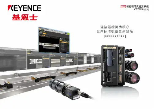
基恩士发布智能引导式视觉系统CV_X100
- 格式:pdf
- 大小:183.33 KB
- 文档页数:1
基恩士视觉系统安全操作及保养规程基恩士视觉系统是自动化领域中的重要设备之一,为确保设备长时间稳定运行,需要进行安全操作及保养。
本文将介绍基恩士视觉系统的安全操作及保养规程,以帮助用户更好的使用和维护设备。
安全操作规程操作前事项在使用基恩士视觉系统之前,需要进行以下操作:1.检查设备:检查设备外表面积、关键部件和接口,如没有异常可以进行操作;2.充电电池:如果是使用电池供电的设备,则需要确保电池充满电,否则需要充电;3.使用合适工具:在拆卸和安装视觉系统的部件时,需要使用适合的工具,不能随意拆卸或装配。
操作时注意事项在操作基恩士视觉系统时,需要注意以下事项:1.调节环境:要避免光照过强或环境嘈杂的地方使用该视觉系统;2.确认程序:在使用基恩士视觉系统运行程序之前,需要检查程序分类无误;3.触电警告:在使用基恩士视觉系统时,请勿将手或其他物体插入任何开口或接口;4.需要较大的维护时,应通知技术人员:涉及到对系统较大改动时,建议请专业技术人员进行操作;5.定期清洁设备:应定期清洁设备外壳、各个传感器,并定期更换灯泡。
保养规程为保证基恩士视觉系统设备正常运行,应定期对设备进行保养:1.每天使用设备前应擦拭设备表面:注意不使用含有乙醇、苯、酮等的化学试剂清洁镜头防止经镜头到设备后面板区域形成腐蚀现象;2.定期清洗设备内外部分:每季度内需要进行系统外壳的清洗,必要时清理内部灰尘和调至镜头,操作时采取不干手触摸等与设备长期接触的部分,使用橡胶手套的操作建议采取一定防电场保护;3.使用环境定期检查:定期清除设备附近的杂物并保证其通风良好,操作时也需注意避免因开窗或开启空调导致的轻微气流影响;4.灯管的更换:灯管使用时长达到 1000 小时时,建议更换灯管以保持设备最佳运行状态。
在更换灯管时需要确保设备断电,并使用正确的灯管进行更换。
总结基恩士视觉系统作为自动化领域中的关键设备之一,具有重要的应用价值。
为保证系统运行稳定,需要注意日常的安全操作和定期保养,注意设备的平稳稳定运行。

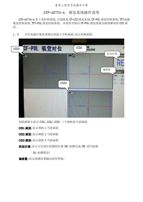
士视觉系统操作手册2020年4月19日ATP-A07VA-A 视觉系统操作说明ATP-A07VA-A 有4套控制系统,分别是CF-LCD 视觉系统,CF-POL 视觉控 制系统,TFT-LCD 视觉控制系统,TFT-POL 视觉控制系统。
本说明书就以CF- POL 视觉系统为例讲解说明CCD 调试。
1.0 开启电源后视觉系统自动进入开机画面,显示初始画面。
CCD1画面:显示相机1当前画面 CCD2画面:显示相机2当前画面 CCD3画面:显示相机3当前画面状态区域:显示正在进行拍摄的结果(OK:拍摄完成,RE:再次拍摄2020年4月19日CCD1初始画面中显示CCD1,CCD2,CCD3三个相机的当前画面。
F-FOL 瓢觉新气一 建状态区RE偏移量「:弋X 0.1V -0.( -N 洲 3 -0.(CCD3NG:拍摄错误)偏移量:表示拍摄结果输出的补偿值。
1.1滑动遥控器介绍1号按键FUNCTION (功能切换功能菜单的显示和非显示2号按键ESCAPE (退出键)设定时返回前面一个界面或者退出3号按键TRIGGER (拍摄键)一齐输入触发4号按键SCREEN (屏幕键)按顺序切换现在显示的画面的显示类别2020年4月19日5号按键VIEW (画面切换)显示查看栏,切换画面的扩大/缩小,显示模式6号按键MENU (主菜单)更改对话框菜单的浓度7号按键(调试功能)在流程编辑画面中切换一般显示/扩大显示1.2进入操作权限按下按键1,弹出功能菜单对话框,移动光标至实用功能,进入对话框,2020年4月19日文档仅供参考,不当之处,请联系改正。
I/O 兑机器PLCtink 存储监视器用户播号切操 存储器使用量选择用户帐号切换,弹出用户帐号切换对话框。
用户选择框中选择Administlator,用户密码是2222。
点击0人进入 操作权限了。
2020年4月19日status功能菜单统计分析 捺测设定历史图保检视实用功能 退出5。
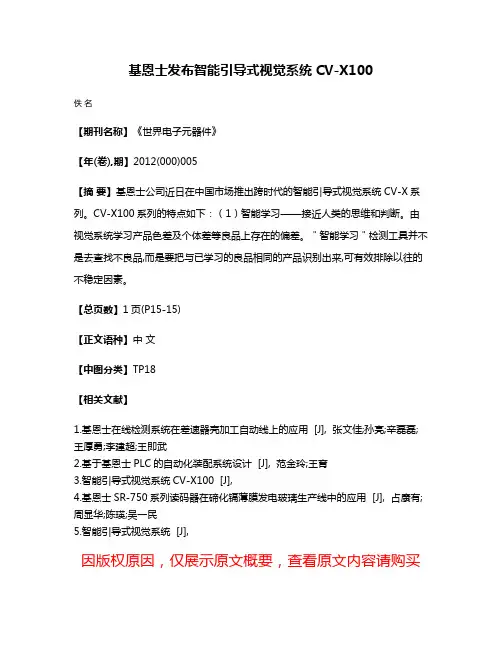
基恩士发布智能引导式视觉系统CV-X100
佚名
【期刊名称】《世界电子元器件》
【年(卷),期】2012(000)005
【摘要】基恩士公司近日在中国市场推出跨时代的智能引导式视觉系统CV-X系列。
CV-X100系列的特点如下:(1)智能学习——接近人类的思维和判断。
由视觉系统学习产品色差及个体差等良品上存在的偏差。
"智能学习"检测工具并不是去查找不良品,而是要把与已学习的良品相同的产品识别出来,可有效排除以往的不稳定因素。
【总页数】1页(P15-15)
【正文语种】中文
【中图分类】TP18
【相关文献】
1.基恩士在线检测系统在差速器壳加工自动线上的应用 [J], 张文佳;孙亮;辛磊磊;王厚勇;李建超;王即武
2.基于基恩士PLC的自动化装配系统设计 [J], 范金玲;王育
3.智能引导式视觉系统CV-X100 [J],
4.基恩士SR-750系列读码器在碲化镉薄膜发电玻璃生产线中的应用 [J], 占康有;周显华;陈瑛;吴一民
5.智能引导式视觉系统 [J],
因版权原因,仅展示原文概要,查看原文内容请购买。
感谢您购买本公司记录仪,本机采用高性能低照度“cmos wxga hd ”高清感光芯片,有独特的超便携式设计,使它可以应用在各个领域,为您带来方便,安全,丰富多彩的日常生活。
主用于车载摄像,是行车中安全事故取证的最佳帮手。
在使用本产品之前,请详细阅读此用户手册,并请保管好此手册。
我们希望本产品,能满足您的需求并长期服务于您!本使用手册在编写和印刷中,可能存在一定文字错误,请谅解。
使用手册印刷过程中,机器因外观和软件的修复过程导致了同该使用手册的部分操作的非一致性,本公司保持最终解释权。
安装记录仪1.关闭引擎,将锁匙从点火器上取出。
2.将tf卡插入记录仪卡槽中。
3.将记录仪用支架垫黏贴安装在汽车的挡风玻璃上或驾驶仪表台上。
4.用电源线将记录仪的usb终端和汽车点烟器连接起来。
5.调整摄像位置,以便获取最佳的拍摄范围。
6.发动引擎,检查机器是否已安装正确。
【注意】(1)请在光线充足、全安的地方安装记录仪。
(2)当机器安装正确,其系统状态led会变成蓝色及显示屏会显示。
使用简介一.使用自动录像功能1.安装完毕后,启动汽车引擎,记录仪将会自动开启并开启自动录像功能。
2.关闭汽车引擎,在6秒后,记录仪保存档并将会关闭。
【注意】记录仪摄像镜头正/反相切换方法,长按【mic键】并保持3秒钟进行切换反相摄像。
长按【录像键】并保持3秒钟进行切换正相摄像,切换正或反相后,关机会自动保存其操作设置。
二.使用手动录像功能1.长按记录仪上的【开启/关闭键】并保持3秒钟。
2.当记录仪启动后,自动开启录像功能。
3.记录仪摄像镜头正/反相切换方法,长按【mic键】并保持3秒钟进行切换反相摄像。
长按【录像键】并保持3秒钟进行切换正相摄像。
(切换正或反相后,关机会自动保存设置)。
4.当再次点擎【录像键】,记录仪将会停止录像功能。
三.使用拍照功能1.长按记录仪上的【开启/关闭键】并保持3秒钟。
2.当记录仪启动后,在自动开启录像功能的状态下。

为何系统?优势照明控制扩展单元提供照明灵活性。
优势KEYENCE 提供各式各样的照明单元以满足几乎所有应用需求。
[世界首创]“可扩展的”控制器结构以经济的方式增强控制CV-5000 系列提供 CCD 扩展单元与照明控制扩展单元,可根据需要将它们添加到主控制器上。
此结构可供用户通过只选择需要的单元来控制成本,又不失适应未来变化的灵活性。
镜面反射的图像示例检测金属表面上是否存在刻字有必要反映出平整金属表面与刻字凹陷之间的差异。
由于金属表面容易反射照明,而刻字则不能,因此,最优方法是使用镜面反射来凸显表面与刻字之间的差异。
照明选择(镜面反射、漫反射、透射光)LED 照明可分为以下三种主要类型:1. 镜面反射型:光线照射到工件上,镜头接收到直接反射的光线。
2. 漫反射型:光线照射到工件上,镜头接收到均匀的环境光线。
3. 透射光型:光线照射到工件上,镜头接收到透射剪影。
[世界首创]LED 照明控制扩展单元轻松控制照明,无需额外布线每个照明控制扩展单元都有两个照明连接器。
最多可将 4 个照明扩展单元连接到一个 CV 控制器上,从而允许同时控制总共 8 个照明*。
控制器的 CCD 配置菜单拥有内置调光控件与可配置的照明模式。
这可为用户提供对照明的完全控制,而无需单独布线和基于 PLC 编程。
通过将照明设定为每次触发时选通来延长 LED 寿命。
还可以通过 CV 用户界面与外部命令控制来调整发光亮度。
* 只要照明的总功率不超过额定功率,就可以使用选配的双头连接线来连接其它照明。
例如,用户最多可以连接 16 个 10 W 的 LED 照明。
照明控制扩展单元控制器CCD 扩展单元镜面反射透射光入射光工件漫反射吸收漫透射光刻字不清楚。
由于包装反光,无法检测印刷字体。
边缘上的缺口不清楚。
由于标签极易反光,因此边缘不清楚。
采用镜面反射采用镜面反射采用镜面反射刻字很清楚。
由于均匀照亮包装表面,反光得到有效消除,显示的印刷字体具有高对比度。
ATP-A07VA-A 视觉系统操作说明ATP-A07VA-A有4套控制系统,分别就是CF-LCD视觉系统,CF-POL视觉控制系统,TFT-LCD 视觉控制系统,TFT-POL视觉控制系统。
本说明书就以CF-POL视觉系统为例讲解说明CCD调试。
1、0 开启电源后视觉系统自动进入开机画面,显示初始画面。
CCD1 CCD2状态区域偏移量CCD3初始画面中显示CCD1,CCD2,CCD3 三个相机的当前画面。
CCD1画面:显示相机1当前画面CCD2画面:显示相机2当前画面CCD3画面:显示相机3当前画面状态区域:显示正在进行拍摄的结果(OK:拍摄完成,RE:再次拍摄NG:拍摄错误)偏移量:表示拍摄结果输出的补偿值。
1.1滑动遥控器介绍1号按键 FUNCTION(功能键)切换功能菜单的显示与非显示 2号按键 ESCAPE (退出键) 设定时返回前面一个界面或者退出 3 号按键 TRIGGER (拍摄键) 一齐输入触发4号按键 SCREEN (屏幕键) 按顺序切换现在显示的画面的显示类别 5 号按键VIEW (画面切换) 显示查瞧栏,切换画面的扩大/缩小,显示模式 6 号按键 MENU (主菜单) 更改对话框菜单的浓度7号按键 (调试功能) 在流程编辑画面中切换通常显示/扩大显示OK 按键7号按键RUN/STOP 键光标 按键1.2进入操作权限按下按键1,弹出功能菜单对话框,移动光标至实用功能,进入对话框,选择用户帐号切换,弹出用户帐号切换对话框。
用户选择框中选择Administlator,用户密码就是2222 。
点击OK,进入操作权限了。
1.3建立视觉模板视觉模板就是视觉系统在生产中比对各种不同位置产品的模板,所以建立模板就是必须选择轮廓明晰,表面清洁的产品。
建立模板的产品必须放置在视觉图片的中央位置,便于视觉系统快速比对产品。
进入权限后,按遥控器背面7号按键,进入Main菜单。
一共有4步与选项,(STEP3与STEP4出厂设置OK不必更改)STEP1 相机设定点击STEP1,进入相机设定画面,可供选择每个相机的设定。

全新更快的速度、更高的分辨率、更多的解决方案。
在世界功能最齐全的单机式影像系统影像系统总目录80 年代90 年代2000 2CV 系列影像系统3CV 系列影像系统CV-5000 系列 登场200320042005 年至 2008 年2009 年以后多种多样的单机式影像系统功能(解决问题的能力)通用型号 产品套装VXXV CV-100CV-2600CV-300CV-2100CV-500CV-3000CV-700CV-5000处理速度4CV 系列影像系统单机式影像系统A.C.E.IIP. 12CV-5000 系列P. 06全新CV-3000 系列P. 305CV 系列影像系统历史CV-5000系列CV-3000系列照明镜头周边索引照明镜头显示器和周边设备同轴照明 CA-DX背光照明 CA-DS 低角度照明CA-DL8 mm CA-LH84 mm CA-LS43.5 mm CV-L38 mm CA-LHS88x 微距CA-LM82x 微距CA-LM250 mm CA-LH2516 mm CA-LS1616 mm CV-L16特殊底座8.4" LCD 彩色显示器CA-MP81/MN81CCD 调整台 CA-S20405.5" LCD 彩色显示器CV-M30条形照明CA-DB 环形照明CA-DRLED 照明控制器CA-DC 圆顶照明CA-DD荧光照明 CA-RCA-LM 系列P. 46CA-D 系列P. 36CA-LH 系列P. 47CV-R/CA-R 系列P. 38CV-L 系列P. 48CA-LS/CA-LHS 系列P. 50CA-M 系列P. 53CV-M 系列P. 54CA-S2040 系列P. 556CV 系列影像系统同类产品中的最佳分辨率11x 高速 500 万像素CCD同类中最快3+1 处理器技术 业界最先进的问题解决工具现在再次得到进步。
隆重推出全新的 CV-5000 系列,它能够毫无困难地解决高难度应用。
基恩士视觉两个工具检测值
摘要:
1.基恩士视觉简介
2.基恩士视觉的工具检测值
3.基恩士视觉的应用领域
4.基恩士视觉的未来发展
正文:
一、基恩士视觉简介
基恩士视觉作为一家专注于机器视觉技术的公司,致力于为客户提供高精度、高效率的视觉检测解决方案。
凭借其先进的技术实力和丰富的行业经验,基恩士视觉已经成为国内机器视觉领域的佼佼者。
二、基恩士视觉的工具检测值
基恩士视觉提供了两款工具检测设备,分别是基恩士视觉检测系统和基恩士视觉测量系统。
这两款设备在工具检测值方面有着显著的优势:
1.高精度:基恩士视觉检测系统可以实现微米级别的检测精度,对于各种精密零部件的检测都能轻松应对。
2.高效率:基恩士视觉测量系统采用了高速图像处理技术,大大缩短了检测时间,提高了生产效率。
3.多功能:两款设备均支持多种图像处理算法,可以根据不同客户的需求进行定制化开发,满足各种复杂的检测要求。
三、基恩士视觉的应用领域
基恩士视觉的工具检测设备广泛应用于以下几个领域:
1.电子制造:用于检测电子元器件的缺陷和尺寸偏差,确保产品质量。
2.汽车制造:用于检测汽车零部件的表面缺陷和尺寸偏差,提高汽车安全性能。
3.医药制造:用于检测药品包装的完整性和标签的准确性,确保药品质量。
4.食品制造:用于检测食品的瑕疵和异物,保证食品安全。
四、基恩士视觉的未来发展
随着工业4.0 时代的到来,对于智能制造的需求越来越大。
ROBOT Communication Sample ProgramKEYENCEVision Sensor MODEL: CV-X100 Series (CV-X100/150/170)Sample Program User’s manualIntroductionThis document is a user's manual for the sample program to use “KEYENCE Vision Sensor CV-X100 Series” connected to the DENSO robot controller.For details and handling of the connected device, refer to the user’s manual of “KEYENCE Vision SensorCV-X100 Series”.Caution: (1) This library is designed exclusively for DENSO robot controller RC8 series and cannot be used for other devices. Note that the functions and performance cannot be guaranteed if thisproduct is used without observing instructions in this manual or modified.(2) All products and company names mentioned are trademarks or registered trademarks oftheir respective holders.----------------------------------------------------------------------------------------------------------------------------------------- This manual covers the following productKEYENCE CV-X100 Series-----------------------------------------------------------------------------------------------------------------------------------------ImportantTo ensure proper and safe operation, be sure to read “Safety Precautions Manual” before using the library.Notice to Customers1. Risks associated with using this productThe user of this product shall be responsible for embedding and using the product (software) on a system and any result from using it.ContentsIntroductionNotice to Customers1. Outline of This Sample (1)2. How to Import (2)3. How to Connect (3)4. Communication Settings for Robot Controller and Device Used (4)5. Sample Program Execution Procedure (11)6. Function (11)7. Static Variable Used in Function (11)8. Function Description (12)9. Sample Program (16)10. Operation Panel Screen (17)1. Outline of This Sample1.1 Target device of sampleThis sample can be used only when a DENSO robot controller (RC8 series) is connected to the CV-X100 series.[CV-X100][Robot controller]1.2 Features of sampleThis sample is provided to use the CV-X100/150/170 native commands required to access CV-X100/150/170 in the robot program. Inclusion of this sample allows customers to establish communication with a robot easily without creating a communication program for CV-X100/150/170. The following shows a position of the sample.Using sample2. How to Import2.1 What is "import"?Retrieving of the files from this library into the project to use in WINCAPSIII is called "import". Importing files enables using the retrieved program.2.2 How to import files to projectSelect [Project] - [Add Existing File...] on WINCAPSIII to import the following files into the project. ・ Main.pns・ KEYENCE_CVX.pcs ・ KEYENCE_CVX_sample.pcsProgram list after import3. How to Connect3.1 RS-232C connection exampleA communication cable needs to be connected to establish communication between the CV-X100 series and a robot controller.To connect to the robot controller via RS-232C, use the optional dedicated cable (KEYENCE PN: OP-26486, OP-26487).[CV-X100]3.2 Ethernet (TCP/IP) connection exampleTo connect to the robot controller via Ethernet, use the optional dedicated cable (KEYENCE PN: OP-66843) or a crossover LAN cable. Also, when a switching hub/router is used, use the cable suitable for the switching hub/router specifications.[CV-X100][Robot controller]4. Communication Settings for Robot Controller and Device UsedUse a teach pendant to adjust the communication settings for the device to be used.4.1 Communication via RS-232C4.1.1 RS-232 communication settings on robot controllerPress [F6 Setting] - [F5 Communication and Token] - [F3 Data Communication] to display the [Data Communication Settings] window.Select the line No.1 for RS-232C and press [Edit] to change the setting value.Make the following settings to use the default RS-232 communication settings for CV-X100.KEYENCE Vision Sensor MODEL :CV-X100/150/170 Ver.1.04.1.2 RS-232C communication settings for CV-X100 seriesPress [Global] - [Communications & I/O] - [RS-232C] to display the [RS-232C (Non-Procedural) Settings] window.Select the desired setting item and change the value so that it agrees with the robot controller setting.Changing the following settings is not required to use the default RS-232 communication settingsfor CV-X100.4.1.3 Other settings for CV-X100 series(1) Trigger SettingsPress [Set Camera] to display the [Camera Settings] window.Press the [Trigger] tab and select [External].Press [Trigger Settings] and check [RS-232C] check box for [Trigger Mode].(2) Output SettingsPress [Output] to display the [Output Settings] window.Select [RS-232C (Non-Procedural)] and press [Select Data] to display the [Output Item Settings]window.Set items to output to the robot controller.4.2 Communication via Ethernet (TCP/IP)4.2.1 Ethernet (TCP/IP) communication settings on robot controller(1) Press [F6 Setting] - [F5 Communication and Token] - [F2 Network and Permission] to display the [Communication Settings] window.Set the IP address and subnet mask of the robot controller so that the robot controller and CV-X100 series are within the same subnet mask.(2) Make client communication settings with CV-100X series.Press [F6 Setting] - [F5 Communication and Token] - [F3 Data Communication] to display the [Data Communication Settings] window.Select the client line No. to use for the Ethernet line No.KEYENCE Vision Sensor MODEL :CV-X100/150/170 Ver.1.0Press [Edit] to change the setting value.Make the following settings to use the default Ethernet communication settings for CV-X100.4.2.2 Ethernet (TCP/IP) communication settings for CV-X100 seriesPress [Global] - [Communications & I/O] - [Network] to display the [Network Settings] window. Set the IP address and subnet mask so that the robot controller and CV-X100 series are within the same subnet mask.Changing the following settings is not required to use the default Ethernet communication settingsfor CV-X100.KEYENCE Vision Sensor MODEL :CV-X100/150/170 Ver.1.04.2.3 Other settings for CV-X100 series(1) Trigger SettingsPress [Set Camera] to display the [Camera Settings] window.Press the [Trigger] tab and select [External].Press [Trigger Settings] and check [Ethernet/IP] check box for [Trigger Mode].(2) Output SettingsPress [Output] to display the [Output Settings] window.Select [Ethernet (Non-Procedural)] and press [Select Data] to display the [Output Item Settings]window.Set items to output to the robot controller.5. Sample Program Execution Procedure(1)Include the function defined program (KEYENCE_CVX.pcs) into the program created by theuser.(2)If the function is called, CV-100X receives and executes the command.(3)CV-X100 generates a response and sends it to RC8.(4)The data received by RC8 is stored to the static variable D_dnCvxData(0), sequentially from thereceived response.(5)The user program processes the next program based on the received data.6. Function6.1 FunctionThe functions with the function names shown in the following table are defined in the standard commands of CV-X100 series.Not all the commands of the device are supported.Function name Process CommandX_PW Changes the program No. PWX_R0 Switches to the run mode. R0X_S0 Switches to the setup mode. S0X_T Trigger input T1 to T4, TA NOTE: There is a limitation on executing each function, depending on conditions of CV-X100 series. For details, refer to the CV-X100 series user's manual.For example, trigger input is accepted only when CV-X100 series is in the run mode.7. Static Variable Used in FunctionStatic variables used in this program are as follows.30 variables are declared as Double type.(Change the number in the specification statement to change the size of received data.)Variable declaration Variable name Descriptionstatic D_dnCvxData(30)Received data static D_dnCvxData(30) as Double Received data (double)NOTE: Static variables can be used in the controller of version 1.3.* or later.8. Function DescriptionX_PWUsage Changes the program No.Syntax X_PW(<Line No.>,<SD No.>,<Program No.>)<Line No.> 1: Universal port, 2 to 3: Reserved8 to 15: Ethernet client port< SD No.> 1:SD1 ,2:SD2<Program No.> 0 to 999Description The program No. of CV-X100 is changed.Example#Include "KEYENCE_CVX.pcs" 'Include the function for communication.Sub MainDim lLineNo as IntegerlLineNo = 8 'Connect as Line No. 8.IF Not (ConnectCVX(lLineNo)) THEN '---- Connection ONPrintDbg "Connect NG"SUBEXITIFEndIF Not(X_PW(lLineNo, 1, 2)) Then 'Switches to Program No.2 of SD1.PrintDBG "Switch NG"SUBEXITIfEndlLineNo '---- Connection OFFDisconnectCVXEND SubUsage Switches to the run mode.Syntax X_R0(<LineNo.>)<Line No.> 1: Universal port, 2 to 3: Reserved8 to 15: Ethernet client portDescription CV-X100 is switched to the run mode.Example#Include "KEYENCE_CVX.pcs" 'Include the function for communication.Sub MainDim lLineNo as IntegerlLineNo = 8 'Connect as Line No. 8.IF Not (ConnectCVX(lLineNo)) THEN '---- Connection ONPrintDbg "Connect NG"SUBEXITEndIFThen 'Changes to the “run mode”.Not(X_R0(lLineNo))IFPrintDBG "Switch NG"SUBEXITEndIflLineNo '---- Connection OFFDisconnectCVXEND SubUsage Switches to the setup mode.Syntax X_S0(<LineNo.>)<Line No.> 1: Universal port, 2 to 3: Reserved8 to 15: Ethernet client portDescription CV-X100 is switched to the setup mode.Example#Include "KEYENCE_CVX.pcs" 'Include the function for communication.Sub MainDim lLineNo as IntegerlLineNo = 8 'Connect as Line No. 8.IF Not (ConnectCVX(lLineNo)) THEN '---- Connection ONPrintDbg "Connect NG"SUBEXITIFEndIF Not(X_S0(lLineNo)) Then 'Changes to the “setup mode”.PrintDBG "Switch NG"SUBEXITEndIflLineNo '---- Connection OFFDisconnectCVXEND SubUsage Inputs a trigger.Syntax X_T(<Line No.>,<Trigger No.>,Result data)<Line No.> 1: Universal port, 2 to 3: Reserved8 to 15: Ethernet client port<Trigger No.> 1 to 4: T1 to T4, -1: TAResult data: Returned as a character string.Description A trigger is inputted.The received data is sequentially stored from D_dnCvxData(0). Themaximum number of received data items is 30. Data exceeding themaximum number is not stored.Example#Include "KEYENCE_CVX.pcs" 'Include the function for communication.Sub MainDim strResults as stringDim lLineNo as IntegerlLineNo = 8 'Connect as Line No. 8.IF Not (ConnectCVX(lLineNo)) THEN '---- Connection ONPrintDbg "Connect NG"SUBEXITIFEndIF Not(X_T(lLineNo, 1, strResults)) Then 'Execute T1 trigger.PrintDBG "Trigger NG"SUBEXITelseP[0] = ( D_dnCvData(0), D_dnCvData(1), D_dnCvData(2) )'Received data to position dataIfEndDisconnectCVXlLineNo '---- Connection OFFEND Sub9. Sample Program'Sample program of a communication command using KEYENCE CV-X series#Include "KEYENCE_CVX.pcs" 'Include the function for communication.Sub MainDim strResults as stringDim iLineNo as IntegerDim iProgNo as IntegerDim iTriggerNo as IntegerDim iSDNo as IntegeriLineNo = 8 'Connect as Line No. 8.iSDNo = 1 'SDNo. 1No.0'Program=iProgNo1 'TriggerNo.1=iTriggerNoIF Not (ConnectCVX(iLineNo)) Then '---- Connection ONPrintDbg "Connect NG"EXITSUBIFEndIF Not (X_PW(iLineNo, iSDNo, iProgNo)) Then '--- Change the program No.PrintDbg "Change NG"SUBEXITIFENDIF Not(X_T(iLineNo, iTriggerNo, strResults)) Then 'Execute the trigger.PrintDBG "Trigger NG"EXITSUBelseP[0] = ( D_dnCvxData(0), D_dnCvxData(1), D_dnCvxData(2) )data 'ReceivedpositiontodataIfEndOFF DisConnectCVXConnectioniLineNo '----END Sub10. Operation Panel ScreenThis sample provides the following operation panel screen. This operation panel uses functions defined by the sample to check operations, etc. after connecting to the device. See the following as an application example of the operation panel.[Main screen]1DescriptionEach button functions as follows.1. Configures the Line No. to connect CV-X100 to. Range: 1 to 3, 8 to 15 (integer)2. Switches CV-X100 to the run mode.3. Switches CV-X100 to the setup mode.4. Configures the SD No. to change the program No. Range: 1 to 2 (integer)5. Configures the program No. Range: 0 to 999 (integer)6. Sends the SD No. set in (4) and the program No. set in (5) to CV-X100 to change the programsettings.7. Configures the trigger No. Range: 0 to 4, -1 (integer)8. Sends the trigger command (the trigger No. set in (7)) to CV-X100 and receives data. 9. Displays the communication result.10. Displays up to 30 items of received data. Displayed data can be switched by using arrows. 11. Clears the received data.12. Initializes the operation panel. Use this button if a system error is caused by using a line No.that does not exist.NOTE: Changing and triggers can be executed only when CV-X100 series is in the run mode.3 7KEYENCE Vision Sensor MODEL :CV-X100/150/170 Ver.1.018Revision HistoryDENSO RobotCommunication Sample ProgramUser's manualKEYENCE Vision Sensor CV-X100/150/170VersionDate Content 2013/2/13 First edition Ver1.0.0DENSO WAVE INCORPORATED●No part of this manual may be duplicated or reproduced without permission. ●The contents of this manual are subject to change without notice. ● Every effort has been made to ensure that the information in this manual is accurate. However, should any unclear point, erroror omission be found, please contact us.●Please note that we will not be responsible for any effects resulted from the use of this manual regardless of the above clauses.。
照相机 1 捕获的图像照相机 3 捕获的图像照相机 2 捕获的图像照相机 4 捕获的图像
使用一部照相机捕获基板的完整图像
使用一部
2 百万像素的彩色照相机使用四部 2 百万像素的彩色照相机 =
约 8 百万像素
CV-3500 1 部照相机捕获的图像CV-3500 4 部照相机捕获的图像
使用四部照相机捕获基板的完整图像
对比度转换调整菜单
对于为每个单独的检验区域设置指定的对比度范围,此过滤器极其有用
增益调整菜单
此过滤器在捕获图像时执行该过程,因此可产生最佳图像,而不影响处理时间。
B (蓝)等颜色组分的数据。
黑白图像原始彩色图像处理颜色对比后的图像
系列”可以使用颜色对比处理功能产生针对特殊应用场合的高对比度灰度图像。
颜色对比处理是一项图像预处理功能,用于将彩色图像转换为高对比度的灰度图像。
此功能将所选的颜色组分指派为最亮的阴影(白色),然后将其它的颜色组分转换为灰色调。
因此这
脏污脏污脏污
1. 原始图像
2. 收缩后的图像(脏污已消除)
3. 扩大后的图像
4. 实时差分处理后的图像(图像 1 减去图像 3)
实时差分过滤器的原理
通过收缩原始图像消除了脏污。
随后通过将收缩后的图像 2 扩展到图像 3,使之恢复到原始图像的相同尺寸。
从原始图像1中减去图像 3,[本示例中每种过滤器的作用]
KC1-0109 Copyright (c) 2007 KEYENCE CORPORATION. All rights reserved. CVInspection2-KC-L-CS 0129-1 E 642155 Printed in Japan
*642155*。
俯视
侧视
像素分辨率
进行尺寸检测的视觉系统用户经常要关心最大分辨率的问题。
首先,必须给视觉系统的像素分辨率定义一个概念。
像素分辨率是由相机中
1 个像素宽度
边缘位置以低于 1 个像素来计算。
边缘测量值(像素)
计算边缘检测区域方向上亮度的平均值是为了获得投射波形。
投射波形区分后,峰值的位置被计算作边缘位置。
次像素原理
会有持续进料的应用
目标物在相机的视野范围内持续移动时,需要考虑相机快门的速度。
模糊不清的图像
高速快门图像低速快门图像
快门速度 = 要求容差 [mm] ÷ 生产线速度 [mm/sec.]
*
6
4
2
3
1
*
KC1-0109
Copyright (c) 2007 KEYENCE CORPORATION. All rights reserved. CVDimension1-KC-L-CS 0129-1 E 642301 Printed in Japan。