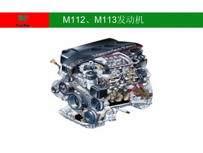
奔驰发动机基础培训ppt
- 格式:ppt
- 大小:5.98 MB
- 文档页数:37


奔驰新M271+EVO学员培训资料轿车动力系统4 缸汽油发动机新M271 EVO学员培训教材目录目录1 情况介绍 111 欢迎 112 时间安排 113 培训课学习目标 114 培训课共识 115 电子培训的问题 22 M271 EVO 的新特性 321 全新271 EVO 发动机 322 M271 EVO 改进的凸轮轴调节器 523 M271 EVO 低噪音链条传动 724 M271 EVO 可调机油泵 1025 M271 EVO 直接喷射 1126 M271 EVO 涡轮增压器 1327 M271 EVO 热量管理和冷却回路 153 理论– M271 EVO 低压和高压燃油系统 1731 W204 低压和高压燃油系统 1732 W204 中的燃油系统 1733 理论 - W204 低压燃油系统 1934 M271 EVO 高压燃油系统 2135 M271 EVO 高压泵 2236 理论 - M271 EVO 高压系统 2637 理论相关的结论介绍- M271 EVO 低压和高压燃油系统 27 4 实践– M271 EVO 低压和高压燃油系统 2841 实践–测试M271 EVO 低压和高压燃油系统 2842 实践 - 测试W204 中的低压燃油系统 2843 实践 - 测试M271 EVO 高压燃油系统 3144 实践相关的结论介绍 - W204 低压燃油系统和M271 EVO 高压系统 325 理论 - M271 EVO 增压空气系统和二次空气喷射系统 3351 增压空气系统和二次空气喷射系统 3352 M271 EVO 增压空气系统 3353 M271 EVO 增压压力控制 3554 理论 - M271 EVO 增压空气系统 3755 M271 EVO 二次空气喷射系统 39PBM1-PA123 学员讲义I目录56 理论 - M271 EVO 二次空气喷射系统 4057 理论相关的结论介绍 - M271 EVO 增压空气系统和二次空气喷射系统 416 实践 - M271 EVO 增压空气系统和二次空气喷射系统 4261 实践 - 测试M271 EVO 增压空气系统和二次空气喷射系统4262 实践 - 测试M271 EVO 增压空气系统 4263 实践 - 测试M271 EVO 二次空气系统 4464 理论相关的结论介绍 - M271 EVO 增压空气系统和二次空气喷射系统 457 实践 - M271 EVO 旋转风门调节 4671 旋转风门调节 4672 M271 EVO 中的旋转风门调节 4673 实践 - 测试M271 EVO 中的旋转风门调节 4774 实践相关的结论介绍 - M271 EVO 旋转风门调节 48 8 实践 - M271 EVO 散热器百页窗 4981 实践 - M271 EVO 散热器百页窗 4982 M271 EVO 散热器百页窗 4983 实践 - 测试M271 EVO 散热器百页窗 5084 实践相关的结论介绍 - M271 EVO 散热器百页窗 51 9 最终测试 5291 最终测试展示 5392 最终测试 5310 结论 54101 结论 54II PBM1-PA123 学员讲义M271 EVO的新特性 2全新271 EVO发动机 212 M271 EVO 的新特性21 全新271 EVO 发动机271 EVO 发动机TT_00_00_000546_FA在本培训单元中您将获得有关271 EVO发动机的新特性和更改信息最近几年中梅赛德斯-奔驰内部名称为M271 的4缸火花点燃式发动机在C级E级CLK和SLK敞篷跑车等车辆中都有卓越的表现M271 EVO这款四缸发动机充分体现了梅赛德斯-奔驰近年来所倡导的量产车小型化理念虽然以采取措施减少油耗为重点但同时也提高了动力性能和扭矩值发动机271 剖面图TT_01_10_000537_FAcom M271 EVO 发动机的新特性M271 EVO 的特性包括改进的凸轮轴调节器低噪音链条传动可调机油泵直接喷射热量管理废气涡输增压PBM1-PA123 学员讲义32 M271 EVO 的新特性21 全新271 EVO发动机com 开发目标保持18升排量不变的情况下重新设计发动机的焦点目标在于减少油耗在保持使用95 RON 燃油不变的情况下提升发动机性能将最高功率从135 千瓦提高到150 千瓦提高了11将最大扭矩从250 牛顿米提高到310 牛顿米提高了24 从而也让客户体验到更多的驾驶乐趣满足EU5 法规优化标准化部件和装配工作流程调整发动机机械部件以适应提升的机械负荷和热负荷并且改善摩擦特性改进前代装备出色的NVH 特性com NVH 最优化噪音和振动最优化通过众多开发步骤改进了M271 EVO发动机的噪音特性根据前代发动机的经验以及发动机早期开发阶段中的计算机模拟对与声学有关的部件做了进一步改进燃油喷射系统从进气口喷射改为直接喷射要求喷油器和高压部件的连接极度精密另一项减少喷油器发出滴答声和改善发动机噪音的措施是一个外形经过重新设计的护盖它安装了具有声学效果的隔音材料M271 EVO 的充气概念已从机械增压器变为废气涡输增压因此进气道进行了彻底改装噪音排放得到进一步改善涡轮增压器特有的噪音如脉动啸声和充气啸声都可利用专门改进的增压器减音器解决改为齿形滚子链后发动机的正时传动在噪音特性方面得到了明显改进通过采用前代装备中的滚子链尤其通过使用最新开发的链条显著降低了兰彻斯特链条传动的噪音等级链条的公差和链节轮廓经过改进后适应了兰彻斯特传动高减噪要求通过优化链条传动布置获得了更多的改进通过对机油盘和手动变速箱进行结构改进进一步改善了噪音排放因此与前代装备相比M271 EVO显著降低了全负荷极限范围内的噪音等级作为典型的涡输增压发动机它只在转速超过2000转每分后扭矩激增时工作声才会提高与前代装备相比在减速模式下总噪音等级则进一步降低这将使M271 EVO能够满足未来车辆对舒适性增加的要求4 PBM1-PA123 学员讲义M271 EVO 的新特性 2M271 EVO改进的凸轮轴调节器 2222 M271 EVO 改进的凸轮轴调节器com 作用运行更快的凸轮轴调节器可以连续可变地调节正时com 设计用于调节进排气锻造凸轮轴的调节器经过优化设计为滑片型调节器该调节器的重量更轻调节速度比以前快了两倍凸轮轴调节器为液压摆动传动装置40°的曲轴转角调节角度–相当于调节器排气处20°的实际角度–是由四个工作腔来完成的凸轮轴扭矩通过这四个腔支持M271 EVO 凸轮轴调节器TT_05_20_000618_FAcom 功能当发动机关闭时弹簧储能销将凸轮轴调节器锁止在其基本位置这样可防止发动机启动时调节器的非受控运动中央阀被设计成一个比例阀并且分别与调节器两个工作腔中的每一个相连一个工作腔连至机油泵一个连至回流管路通过对前代凸轮轴调节器的进一步开发重量降低了34调节速度增加了此项改进可通过引入一个中央单向阀实现从而降低了液压比扭矩凸轮轴调节策略最大调节范围达到了70°曲轴转角进气30°曲轴转角排气40°曲轴转角在部分负荷范围内内部废气循环率可达约20 使得最大耗油量减少8-10精确的设定点调节及最窄的凸轮轴峰谷值是遵从发动机点火不良限制所需间隔的先决条件对此特别关注的是调节液压促动的凸轮轴定位器及其位置控制其结果是曲轴转角范围控制稳定性小于±15°在大部分节气门开启范围内调节选项–包括所述的扫气模式反转模式 - 有效减少耗油量和排放PBM1-PA123 学员讲义52 M271 EVO 的新特性22 M271 EVO改进的凸轮轴调节器M271 EVO 进气和排气凸轮轴调节器TT_05_20_000619_FA6 PBM1-PA123 学员讲义M271 EVO 的新特性 2M271 EVO低噪音链条传动 2323 M271 EVO 低噪音链条传动众多改变使得链条传动产生的噪音显著降低com 设计新型齿形链节发动机正时链的滑轨较长具备更好的导向作用这种改进的导向作用可防止发动机正时链振动M271 EVO 链条传动TT_05_10_000539_FAcom 功能由曲轴驱动的新型主正时链驱动两根凸轮轴PBM1-PA123 学员讲义72 M271 EVO 的新特性23 M271 EVO低噪音链条传动M271 EVO 链条张紧器使用新型棘爪式链条张紧器张紧M271 EVO 的主正时链此类链条张紧器一旦已取下不得重复使用重新安装使用曾完全松开的链条张紧器可能会导致发动机损坏在安装新的链条张紧器之前必须先阅读维修间资料系统中的维修说明M271 EVO 棘爪式链条张紧器TT_05_10_000640_FAcom M271 EVO 兰彻斯特平衡器作用兰彻斯特平衡器安装在曲轴箱下方它可对4缸发动机因设计原因而出现的二阶自由惯性力进行补偿设计如其前代装备一样气缸曲轴箱也由压铸铝制成采用铸铁衬套的缸套经过精密珩磨进一步降低了摩擦与前代发动机一样仍然使用卧式单件式压铸铝兰彻斯特壳体以及单个无衬套的滑动轴承组合式兰彻斯特轴的使用提高了成本效益因此将两根碳钢管轴代替之前使用的锻造轴插入兰彻斯特壳体的曲轴通道不平衡质量部分则被固定到轴上不平衡质量部分的前端同时可用于在铝制壳体内进行定位和提供轴向支撑平衡轴用三个巴氏合金轴承支撑与前代装备相比不平衡质量区域内较小的轴承直径能够显著减少摩擦曲轴与前代发动机一样采用铸造曲轴有八个平衡重8 PBM1-PA123 学员讲义M271 EVO 的新特性 2M271 EVO低噪音链条传动 23M271 EVO 兰彻斯特平衡器TT_03_30_000540_FAM271 EVO 兰彻斯特轴TT_03_30_000541_FA功能具有以下优点通过将不平衡轴颈直径减半节约燃油消耗量高动态剪切力令摩擦减少特别是兰彻斯特转动速度非常快高达 13000 转每分因此使摩擦显著下降简化的系统和部件减少了成本费用更小且统一的轴承直径刚性轴降低了制造和组装成本可以省略组装整体锻造轴所需的驱动端保护罩不平衡质量的直径包括装配工作和螺纹连接采用工艺精细的轴承座和空心轴代替锻造轴而减轻了重量兰彻斯特壳体内直接驱动和部分整合的可调叶片式机油泵与M271 量产装备兼容PBM1-PA123 学员讲义92 M271 EVO 的新特性24 M271 EVO可调机油泵24 M271 EVO 可调机油泵com 作用可调叶片式机油泵根据所需的机油压力提供必要的机油量com 设计可调叶片式机油泵通过凸缘安装在兰彻斯特壳体的后轴承座前端进气侧平衡轴通过一对齿轮驱动机油泵此时的机油泵驱动为下传动M271 EVO 可调机油泵TT_18_10_000622_FA1 至曲轴箱的加压出油口 6 机油泵壳体2 输入轴 7 进气道3 定位环 8 滑片4 安装套筒 9 调速油道5 定位环弹簧com 功能调节通过机油泵的新油侧进行从主油道流出的调速机油进入调速油腔此时的机油将压向叶轮泵的弹簧储能定位环如果主油道内的机油压力到达规定的压力定位环将克服弹簧力移动这样减少了滑片的偏心距因而减少了机油泵的有效尺寸进而减小了泵容积因此机油压力不会进一步增加10 PBM1-PA123 学员讲义M271 EVO 的新特性 2M271 EVO直接喷射 2525 M271 EVO 直接喷射com 作用与前代发动机相比直接喷射可提高压缩比因此效率更高燃料分配均匀且成分配比理想燃油喷射压力最高可达140巴M271 EVO 直接喷射TT_07_70_000548_FA18 油轨 Y763 3 缸喷油器20 高压燃油泵 Y764 4 缸喷油器201 驱动器驱动装置 Y94 油量控制阀B46 油轨压力传感器 A 来自油箱的燃油供给燃油低压Y761 1 缸喷油器 B 至油轨的燃油供给燃油高压Y762 2 缸喷油器com 设计单级柱塞泵作为高压泵使用燃油经由高压油轨注入各喷油器成30度角喷入燃烧室M271 EVO 高压泵TT_07_70_000544_FAPBM1-PA123 学员讲义112 M271 EVO 的新特性25 M271 EVO直接喷射com 功能为这类直接喷射设计的燃烧系统根据燃烧稳定性稳固性和高比输出功率83千瓦升进行开发电磁阀喷油器的构造角位置要求有额外的喷射倾角以防缸壁包括进气门涂层上出现沉积物喷油器的每个喷嘴均针对穿透深度均质化能力和油滴大小等进行了开发并且经过改进以适应气缸的内部压力状态和充气运动这也影响汽油的稀释以及炭黑生成在此方面进行了关于喷射形状和喷射方案的采用多孔喷油器的深入研究最成功之处在于采用了高燃烧稳定性和最低排气及微粒排放的类型通过使用加大了扰流的进气口能够提高燃烧速率避免在冷启动后壁上出现任何沉积物为了防止喷射的油流直接被燃烧室壁弹回对不同的活塞燃烧腔形式进行了深入研究这样可在排放机油稀释和耗油量之间提供最佳折中方案因此黑烟值在宽泛的特性图谱范围内均低于01 的烟尘指数安装了具有致偏谐振腔边缘和高容纳油流能力的活塞结构改善了火花塞区域内混合气的气流导向如冷启动12 PBM1-PA123 学员讲义M271 EVO 的新特性 2M271 EVO 涡轮增压器 2626 M271 EVO 涡轮增压器com 作用涡轮增压器产生要求的增压压力07-12 巴com 设计涡轮增压器的设计可承受1050 °C的高温被焊接到带双管LSI排气歧管的发动机排气侧轴承壳体用水冷却涡轮轴与发动机油回路相连M271 EVO 涡轮增压器TT_14_10_000547_FA501 增压压力控制阀门 A 冷却液供液管路502 增压压力控制阀门真空组件 B 冷却液回流管路503 消音器 C 发动机供油管路Y101 分流空气转换阀发动机回油管路com 功能所选择的过压控制系统可以产生一个基础的增压压力这相当于一个储压器并且改善了动态特性涡轮增压器控制根据图谱和负荷调节的增压压力通过促动增压真空室实现此增压真空室靠弹簧力固定在其基本位置废气旁通阀关闭弹簧可承受约300毫巴的增压压力真空室通过增压压力传感器Y315进行调节它由发动机控制单元促动PBM1-PA123 学员讲义132 M271 EVO 的新特性26 M271 EVO涡轮增压器为此发动机控制单元分析以下发动机管理的传感器和功能增压空气温度增压空气温度传感器B178增压压力节气门的压力传感器上游B286进气压力压缩机轮的压力传感器上游B2815来自驾驶员的加载要求油门踏板传感器B37发动机转速曲轴霍尔传感器B70防爆震控制系统变速箱过载保护过热保护减速空气在开始减速后由于轴压缩机轮和涡轮叶轮的质量惯性涡轮增压器需继续旋转一会儿当节气门执行元件M166 迅速关闭时会导致增压压力冲击波流回到涡轮增压器该增压压力冲击波可能会对压缩机泵轮产生低的卸载率和高的增压比这将导致增压器泵送短啸声和机械应力开启排气阀可防止此冲击波因快速卸压进入进气道如果ME-SFI [ME]控制单元检测到由负荷向减速模式过渡将促动旁通空气转换阀旁通空气转换阀随即开启旁通管增压压力则经由旁通管供给压缩机泵轮的进气侧使增压压力降低在增压模式下整合弹簧关闭旁通空气转换阀另外由于阀活塞处的压力状况相同增压压力也会经由小孔传给阀膜片的后侧因此阀门保持关闭与压缩机增压相比的优点与机械增压器相比废气涡轮增压具有运行能耗降低重量轻噪音低等优点遵守涡轮增压器的密封说明固定歧管的螺母必须由内向外拧紧至最大扭矩15牛顿米此后必须再次拧紧最大扭矩仍为15牛顿米这可确保排气歧管在气缸盖的密封表面处展开14 PBM1-PA123 学员讲义M271 EVO 的新特性 2M271 EVO热量管理和冷却回路 2727 M271 EVO 热量管理和冷却回路com 作用热量管理的作用在于根据需要利用图谱控制的双盘节温器来调节冷却液回路com 设计M271 EVO 冷却回路TT_20_00_000549_FA1 散热器 8 节流阀2 膨胀水箱 9 切断阀3 变速箱油冷却器 10 曲轴箱4 硅酸盐凝胶罐 11 风挡玻璃清洗液加热器5 具备三盘功能的双盘节温器 12 发动机油冷却器6 冷却液泵 13 双阀7 涡轮增压器 14 加热器热交换器与量产发动机所用的冷却液回路及其单盘节温器相比电子控制的具备三盘功能的双盘节温器可确保M271 EVO 中图谱控制的预热控制com 功能M271 EVO 双盘节温器TT_20_10_000550_FA规定的冷却液温度根据需要经由双盘节温器进行调节同时提高部分负荷下的机油和发动机温度会减少摩擦力PBM1-PA123 学员讲义152 M271 EVO 的新特性27 M271 EVO热量管理和冷却回路通过显著降低高负荷范围内的发动机温度可获得最佳的发动机效率在冷启动过程中关闭特性图谱节温器和加热器切断阀可使冷却液回路停止工作冷却液停止流过气缸盖这样在预热阶段系统使燃烧室能够快速升温双盘节温器控制策略如果冷却液达到80 °C节温器将开启旁通回路在温度为105 °C的部分负荷范围内节温器也会开启和打开冷却液沿车辆散热器方向的通路在全负荷或高负荷期间冷却液温度分阶段降至90 °C或80 °C在冷启动和驾驶员请求加热时通过开启加热切断阀来取消不循环回路切断阀开启时可提供80 °C的全流量进行加热这可确保为客户提供最适宜的加热舒适性当负荷要求增加和或转速提高时不循环回路状态可通过短暂电加热腊筒结束基于安全理由节温器和加热切断阀在转速超过4000转每分时如节温器中的电加热器筒失效时中止工作加热切断阀在未通电时开启16 PBM1-PA123 学员讲义理论– M271 EVO低压和高压燃油系统 3W204低压和高压燃油系统 313 理论– M271 EVO 低压和高压燃油系统31 W204 低压和高压燃油系统在本培训单元中您将进一步了解M271 EVO 中低压和高压燃油系统的知识分组培训师将大家分成两组您将在小组中完成该主题做完练习之后小组中的一名学员将介绍你们得到的结论我们希望您喜欢这些练习32 W204 中的燃油系统com 作用燃油系统为发动机提供必要的清洁燃油com 设计M271 EVO 燃油系统TT_47_00_000575_FAcom 功能燃油输送燃油泵从油箱右半部分的燃油输送单元抽出周围的燃油并将燃油输送至燃油过滤器的进油口燃油过滤器单元清洁燃油燃油经由两个出油口离开过滤器溢流阀与一个出油口相连另一个出油口与发动机供油管路相连两个出油口的压力同时增加溢流阀在压力大于等于约35 巴时开启一个分流口分流的燃油流到油箱左侧的抽吸喷射泵燃油从那里流到右侧的燃油输送单元发动机的分配油轨经由第二个出油口供油PBM1-PA123 学员讲义173 理论– M271 EVO低压和高压燃油系统32 W204 中的燃油系统电子燃油压力控制燃油压力传感器记录燃油压力并将电信号传输至燃油系统控制单元燃油系统控制单元将与记录的压力有关的CAN信号传输至发动机控制单元发动机控制单元检查压力的可靠性并将当前燃油压力请求传输至燃油系统控制单元燃油系统控制单元通过改变启动信号脉冲宽度调制校正燃油泵的启动这样可改变燃油泵的转速以及燃油压力和输送率18 PBM1-PA123 学员讲义理论– M271 EVO低压和高压燃油系统 3M271 EVO 高压燃油系统 3434 M271 EVO 高压燃油系统com 作用高压燃油系统向发动机提供足够高的燃油压力和足量的燃油com 设计高压系统包括三个主要部件 - 带油量控制阀的高压泵带油轨压力传感器的高压油轨和喷油器M271 EVO 燃油喷射系统TT_07_70_000593_FA18 油轨 B 至油轨的燃油供给燃油高压20 高压燃油泵 Y761 1 缸喷油器201 驱动器驱动装置 Y762 2 缸喷油器202 燃油压力缓冲器 Y763 3 缸喷油器B46 油轨压力传感器 Y764 4 缸喷油器A 来自油箱的燃油供给燃油低压 Y94 油量控制阀com 功能燃油由低压回路经低压进油口流到高压泵低压燃油经由油量控制阀流到油泵内的高压压缩机室在此借助于金属波纹管进行压缩经压缩的燃油随后通过不锈钢管路流到油轨此后系统利用喷油器将燃油喷入燃烧室油轨压力由油量控制阀进行调节PBM1-PA123 学员讲义213 理论– M271 EVO低压和高压燃油系统35 M271 EVO高压泵35 M271 EVO 高压泵com 作用新的直接喷射系统单柱塞高压泵产生所需的油轨压力com 设计高压泵固定在气缸盖的左后其驱动则由进气凸轮轴提供Oldham离合器连接凸轮轴与高压泵com 功能进气凸轮轴通过Oldham离合器驱动高压泵高压泵的驱动装置促动泵内装有四个凸轮的偏心轴泵传动轴的四个凸轮促动滚柱挺杆从而驱动弹簧储能活塞此活塞将带走缸内一定量的机油带走的机油会使金属波纹管更为膨胀金属波纹管的扩大会在油泵的燃油室内产生燃油高压燃油通过不锈钢管路经由排油阀流到油轨这种分离方式意味着油泵的驱动装置和供油装置之间没有直接联系偏心轴和气门挺杆的润滑由泵内的独立出油装置提供这种出油装置无需更换润滑油道上装有缓冲器以补偿机油的热膨胀损失M271 EVO 高压泵TT_07_70_000553_FA22 PBM1-PA123 学员讲义理论– M271 EVO低压和高压燃油系统 3M271 EVO高压泵 35高压泵的拆卸拆卸高压泵之前确保发动机已转至TDC 上止点后的52°曲轴转角警告伤害风险高压泵可能突然弹出不要拆开高压泵处的低压管路燃油软管但可剪断软管这样更便于拆卸高压泵注务必更换连接高压泵的低压管路燃油软管这可确保系统保持密封高压泵的安装。

Cars • Gasoline engineEngine 275Initial trainingInformation moduleAs at 03/03Contents04.03.2003Page Title1Engine 275 - an overview8Engine mechanics M275 / M28516ME 2.7.1 fuel-injection and ignition system26Fuel system30Exhaust gas turbocharging49Comparison of exhaust gas turbocharger and mechanical supercharger53Exhaust-gas system54ECI ignition system62Information unit engine 285Engine 275 - an overview 04.03.2003P00.00-2256-50P00.00-2821-50P00.00-3081-50Highlights M275The new V12 with bi-turbo chargingHigh-tech perfection is promised by the new 12-cylinder engine, which will be available as of autumn2002 in the model refined S-Class. This V12-cylinder bi-turbo comes with commanding performancevalues: the engine develops a rated output of 368 kW at 5,000 rpm and a rated torque of 800 Nm at1,800-3,500 rpm.This power unit has a generously rated surplus in output and, in particular, torque and this is available atconstantly harmonious output and torque development. In keeping with the character of a luxury sedanthe new motorization comes with a perfectly smooth operation and an harmonic noise design.GT01_00_0016_C71Taking all viewpoints into consideration the technical realization of the goals set called for a V12-conceptwith 5.5 l displacement, 60 degree cylinder bank angle and bi-turbo charging.Engine breathing is supported by a turbocharger with "wastegate-control system" for each cylinder bank.Exhaust gas turbocharging development mainly focuses on the finest response characteristics incombination with the achievement of maximum torque at as low as possible engine speed. Apart fromthis special emphasis was placed on the acoustic characteristic.Output and torque in abundanceIn comparison to the predecessor engine the rated output and rated torque for the new engine have beenincreased by approx. 30 % or 50 %. Because a corresponding increase in displacement was ruled out dueto the wish to keep to moderate fuel consumption and a compact design, a slightly reduced displacementwith two exhaust gas turbochargers and charge air cooling was selected. The model refined S-Classachieves thus outstanding performance with excellent acoustics, a superb degree of vibrational comfortand, in view of the performance data, adequate fuel consumption.Smooth operation and noise emissionOn a 12-cylinder engine with a cylinder angle of 60 degrees, all forces and torques of the 2nd order arecompletely balanced as a matter of principle. Thus the greatest possible degree of smooth operationwithout additional balance shafts is a given factor.All engine parts are designed using ultramodern calculation and testing methods in terms of rigidity andvibrational characteristics. The improvement in vibrational characteristics is contributed to in particularby a bedplate design with gray cast iron inserts on the crankshaft main bearings. The oil pan iscompletely decoupled from the crankcase in terms of vibrations. Combustion noise is dampened by theinstalled dual ignition, which serves to keep the pressure gradients in the combustion chamber at a lowlevel and which minimizes cycle scatter for each individual combustion procedure. Noise reduction wasalso achieved by the damping through the exhaust gas turbochargers on the air and exhaust-gas sides aswell as the water jacket of the water-cooled generator.GT01_00_0017_C71WeightDespite the additional exhaust gas turbocharger, engine-side charge air cooler and the reinforced beltdrive the M275 only weighs 270 kg and thus achieves an excellent power/weight ratio of 0.65 kg/kW.The following lightweight components are used:∗cylinder head cover made of die-cast magnesium∗weight-optimized cracked, forged steel conrod∗die-cast aluminum for upper and lower section of crankcase∗lightweight silitec cylinder liner∗weight-optimized elastoval piston∗ a 3-valve design with one camshaft per cylinder bank∗weight-optimized crankshaft and dynamic balancer∗an oil pan made of die-cast aluminumTechnical data comparisonSales designation CL 600CL 600S 600SL 600 * Vehicle model215.378215.376220.176230.476 Engine model137.970275.950Cylinder arrangement / number / angle V12 / 60°Valves / spark plugs per cylinder 3 / 2Continuous fuel-injection and ignition system ME 2.7ME 2.7.1Turbocharging with charge air cooler (intercooler)Air supply Naturally aspiratedengineTotal displacement cm³5,7865,513Rated output kW (hp) at rpm270 (367) at 5,500368 (500) at 5,000Rated torque Nm at rpm530 at 4,100800 at 1,800 - 3,50013.414.7Fuel consumption (New European Driving Cycle)Super Plus l/100 km/hAcceleration 0 - 100 km/h s 6.3 4.8* Market launch 04/2003Performance graph M137Performance graph M275P01.00-2341-73GT01_00_0018_C73Comparison of M275 / M285 with M137Engine 137 (ME 2.7)Engine 275 / Engine 285 (ME 2.7.1)AdvantageECI ignition system (AC voltage ignition system with integrated ionic current measurement), ignition voltage 30 kV, two spark plugs per cylinder ECI ignition system (AC voltage ignition system withintegrated ionic current measurement), ignitionvoltage 32 kV, two spark plugs per cylinderImprove ignition performance and reliabilityNo knock sensors, recognition of knocking combustion by using the ionic current measurement 4 knock sensors¾A29/1 and A29/2 on left cylinder bank¾A30/1 and A30/2 on right cylinder bankRecongition of knocking ignition over the knocksensors offers the availability of an optimally gradedperformance map for the monitoring of smoothoperationNaturally aspirated engine One exhaust gas turbocharger (bi-turbo) made ofsteel casting for each cylinder bank.Enormous generation of power for a relatively low fuel consumptionFuel pump is drived by fixed12V À constant delivery volume Fuel pump (max. delivery rate approx. 245 l/h) isdrived by PWM signal (control by a fuel pump controlmodule) À deliver according to demand¾Less wear and noise¾Saves energyA total of 8 O2 sensors for in front of and behind the four firewall catalytic converters respectively A total of 4 O2 sensors, 2 in front of and 2 behindthe firewall catalytic converters respectivelyReduction of the number of componentsFulfillment of Euro 4 and LEV 1Cylinder Shut Off: the left row of firing cylinders areshut-off when idling or when running in a low loading situation -----Priority is given to obtaining a performanceadvantageCamshaft adjustment-----DittoDetection of combustion misfires through ionic current signals Detection of combustion misfires through ioniccurrent signals and through smooth operationevaluation using crankshaft position sensor (L5)Optimize the combustion misfiring detection to suitturbocharged engineEngine mechanics M275 / M28504.03.2003 Crankcase The crankcase and oil pan for the M137, M275 and M285 engines are designed as follows.Legend:1Upper crankcase section made of die-castaluminum2Weight-optimized crankshaft and dynamicbalancer3Upper crankcase section made of die-castaluminum4Rubber gasket between crankcase bottomsection and upper section of oil pan5Upper section of oil pan made of die-castaluminum6Oil pan bottom section made of die-castaluminumP01.40-2029-09 The upper section of the oil pan in the S-Class is designed as shown. The front axle design of the variousvehicle models (S-, SL-Class and Maybach) means that the oil sumps have to be located in different places.Service tipThe following must be noted when removing and installing the upper oil pan:A copper connecting link is located at one of the screws, which serves to set up the ground connectionbetween the oil sensor and the crankcase.Never forget this when assembling!GT03_00_0001_C71The oil pan constriction on the M275 consists of two parts. This has a positive effect on the sealingconcept.The upper part of the oil pan is sealed against the lower part of the oil pan using a silicone sealantSpare Part No. A 002 989 73 202/50 ml.The upper part of the oil pan is sealed against the crankcase by means of a rubber seal which is vibrationdampening and also serves to optimize noise generation.Aluminum crankcase with gray cast-iron insertA genuine highlight is the particularly innovative design of the crankcase.The crankcase is of a two piece bedplate design. Massive gray cast iron inserts in the area of the lowercrankcase section's main bearing achieve improved noise generation characteristics.The very compact design of the crankcase does not lead to any increase in the size of the enginecompared to previous models despite turbocharging. This, together with the light-weight constructiontechnology used, leads to a total engine weight of just 270 kg which represents an increase in weight ofjust 50 kg compared to the basic M137 engine.The increase in weight is due to the additional coolant compressor and the extraordinarily powerful 350 Aalternator.GT03_20_0005_C01In order to meet the demands of higher heat and pressure loads, the wall between the cylinders of theupper crankcase section have been widened compared with the M137 by 2 mm to 8 mm and in eachcase 3 water cooling bores (1 and 2) have been integrated into the walls.The cylinder bore has been reduced compared with the M137 from 84.0 mm to 82.0 mm. By contrast thecylinder spacing of 90 mm and the stroke of 87 mm have not been altered.Water-cooling bores (1 and 2) for cooling wallsGT03_20_0006_C011The cylinder liners are made up of an alloy of aluminum-silicon (silitec). They have a wall thickness of2.5 mm.Advantage:¾lower cylinder thermal distortion¾lower noise and less pollutant emissions¾lower weight and greater dimensional stability.GT03_20_0007_C01Piston The cast pistons and piston ring are designed to cope with the extremely high pressures andtemperatures. For the realization of the smallest, noise-relevant plays and for the purpose of improvingthe emergency running characteristics, the gravity die-cast pistons have been galvanically coated withiron.The piston pins have been optimized in accordance with the acting loads both in terms of outer diameterand wall thickness.Piston cooling is supported by oil spray nozzles.2Connecting rodForged steel conrods made of crack-capable forged steel are used. To protect the extremely high loadsDaimlerChrysler is using a high-strength forged material for the first time.As previously with the 137 engine for reasons of higher dimensional accuracy in the M275 and M285engines the lower connecting rod eye is cracked (broken) and bolted to the crankshaft's main bearing.GT_03_10_0003_C01Cylinder headThe aluminum cylinder heads come with the 3-valves-per-cylinder technology familiar from the M137.Each cylinder bank contains a camshaft, which actuates both the inlet and exhaust valves by means ofcam followers.The M275 and M285 engines do not need camshaft adjustment, as their torque increasing function incombination with turbocharging is rendered superfluous.Chain driveCamshaft drive ensues from the crankshaft by means of a twin roller chain. A sprocket wheel is used inthe V-center for deflection purposes. Otherwise the chain is routed through slightly bent slide rails.The chain tensioning force is achieved over a tensioning rail by means of a hydraulic chain tensioner.In order to improve the noise characteristic of the chain drive, the sprocket wheel of the crankshaft, theguide wheel and the camshaft are rubberized.To optimize the overall length the oil pump drive has been located downstream of the timing chain. Theoil pump chain drive is designed as a single roller chain.GT_01_30_0016_C01Engine control How is the engine control's basic adjustment made?The basic adjustment is 30° ATDC. At 30° ATDC the groove (6) of the camshaft at left and right iscentered relative to the separating surface for the cylinder head cover towards the inner-V. To fasten thecamshafts, the special tool familiar from the M137 can be used. The groove on the crankshaft gear (2)points to the mark on the crankcase. The guide wheel (3) without a mark need not be considered.1Copper plated connecting link, two each for camshaft sprocket adjustment2Groove in crankshaft3Guide wheel without mark4Mark on camshaft sprocket at right R5Mark on camshaft sprocket at left L6Groove in camshaftP05.10-2144-06Crankcase ventilation of M275/M285The blow-by gas is aspirated by the vacuum in the charge air distribution pipe, or turbocharger intake pipe.It is routed from the timing-chain compartment to the centrifugal oil separator where the oil is separated from the blow-by gas.Following this, the blow-by gas is routed to the pressure regulating valve. The separated oil is fed back to the oil pan over the timing-chain compartment.Partial load ventilationDuring partial load ventilation the air is routed across the check valve into the charge air distribution pipe.Full load ventilationDuring full load ventilation the partial load ventilation line is closed by the boost pressure applied to the check valve. The air separated from the oil is then routed to the Turbocharger intake pipe downstream of the air cleaner.GT18000003C81Pressure regulating valveCharge air distribution pipeTurbocharger intake pipe Check valve,full load ventilationCentrifugal oil separatorCheck valve,partial load ventillationOil separator/Pressure regulating valveA centrifugal oil separator integrated into the ventilation system of the engine on the left-hand camshaftachieves excellent removal of oil under all operating conditions.An additional pressure regulating valve ensures that there is adequate vacuum in the crankcase duringthe air inlet suction and turbocharging processes as well as under conditions of partial loading and fullloading.At a specific vacuum (> 50 mbar) in the turbocharger intake pipe the connection to the crankcase issealed by means of a diaphragm in the pressure regulator valve.If the pressure in the crankcase rises above a specific value, the diaphragm is opened and thus theconnection to the turbocharger intake pipe set up again.GT_01_30_0017_C71ME2.7.1 fuel-injection and ignition system04.03.2003Motor electronics control module 2.7.1The electronic engine management is an advanced development of the ME 2.7 of the M137. It includesthe engine control function including all diagnoses and is networked over the CAN-C databus with furtherelectronics. The control module is housed in a ventilated electronic module box along with otherelectronics.The engine control function has been adapted to the bi-turbo engine:∗The pressure in the charge air distribution pipe and the corresponding temperature are recorded forcalculation of the aspirated air mass using separate pressure and temperature sensors.∗The boost pressure is recorded by a second pressure sensor upstream of the throttle valve and servesthe boost pressure control.∗Boost pressure is regulated by the wastegate valve in the exhaust gas turbocharger.P07.08-2017-01∗Torque momentum coordination and the engine's emergency (limp-home) function have been adaptedto the turbocharger-specific requirements.∗The diagnosis has been extended by the charger protection feature, which serves to prevent anyimpermissibly high turbine wheel speed.∗The signals from 4 knock sensors are evaluated for knock identification.∗The ionic current misfiring detection familiar from the 137 engine has been adapted to suit therequirements of a highly-supercharged engine. The detection quality was able to be improved bycontinuously comparing it with a speed uniformity analysis on the crankshaft.∗In order to safeguard the exhaust gas turbocharger and the three way catalytic converters against toohigh exhaust gas temperatures, a model-based exhaust gas temperature control has been introduced.∗The communication of ME control module with the alternator via a bi-serial communication interface.E ngine fuse and relay box (K40/8)I n the engine compartment the S and CL 600 models have had an additional relay box installed. The following components are contained in this relay box:K40/8kW Charge air cooler recirculationpumpK40/8kVMotronic relayK40/8kX Intank fuel pump relay(only for S 55 AMG, CL 55 AMG)F use 87Motronic 1F use 88Motronic 2F use 89reserve P20.00-2118-04 F use 90Charge air cooler recirculationpumpF use 91reserveK40/8C ontinuous fuel injection system (overview)B OSCH M E 1.0M119M120∗Control through hot film mass air flow sensorM E 2.0M112M113∗Control through hot film mass air flow sensorM E 2.1M111∗Control through hot film mass air flow sensorM E 2.7 M E 2.7.1 M E 2.7.1M137M285M275∗Control through hot film mass air flow sensor∗Pressure motor control∗Pressure motor controlM E 2.8M112M113∗Control through hot film mass air flow sensor M anifold air pressure sensor for monitoringM E 2.8.1M112 MLM113 ML∗Pressure motor controlV DO M SM M166∗To 08/2001 control through hot film mass air flow sensor∗As of 09/2001 pressure motor controlS iemens S IM4M111 EVO∗To speed 2,000 rpm control through hot film mass air flow sensor∗As of speed 2,000 rpm manifold air pressure controlLocation of the components on the M275/285 engine71Check valve (purge control)B28/7Pressure sensor downstream ofthrottle valve actuatorN91ECI power supply unitN92/1ECI Ignition module for right cylinderbankN92/2ECI Ignition module for left cylinderbankY31/5Boost pressure control pressuretransducerY32Air pump switchover valveY101Divert air switchover valveP07.61-2735-06Location of the components5/1Charge air cooler (left bank)5/2Charge air cooler (right bank)121/1Air cleaner (left bank)121/2Air cleaner (right bank)B17/8Charge air temperature sensorB28/4Pressure sensor downstream of aircleaner on left cylinder bankB28/5Pressure sensor downstream of aircleaner on right cylinder bankB28/6Pressure sensor upstream of throttlevalve actuatorM16/6Throttle valve actuatorN91ECI power supply unitP07.61-2729-06Location of the componentsB6/2Camshaft Hall sensor (left bank)B6/3Camshaft Hall sensor (right bank)L5Crankshaft position sensorP07.61-2731-06Location of the components126/1Air injection shutoff valve on left bank(combination valve: check valveintegrated)126/2Air injection shutoff valve on rightbank (combination valve: check valveintegrated)B11/4Engine coolant temperature sensorB40Oil sensorM33Electrical secondary air injectionpump(illustration shows the 275 engine,on vehicle side for the 285 engine)P07.61-2734-06Location of the componentsA29/1Front knock sensor (left bank)A29/2Rear knock sensor (left bank)A30/1Front knock sensor (right bank)A30/2Rear knock sensor (right bank)G2AlternatorP07.61-2730-06Location of the componentsG3/3x1Plug connector for O2 sensor(upstream of left catalytic converter)G3/4x1Plug connector for O2 sensor(upstream of right catalyticconverter)B Test connection for divert air valveP07.61-2732-06Location of the components110/1Turbocharger intake pipe110/4Divert air valve110/6Charge air pipe110a Exhaust gas turbocharger (left)110b Exhaust gas turbocharger (right)B Exhaust gasD Fresh gas (after air cleaner)E charge airP07.61-2733-06Fuel system04.03.2003GeneralIn order to prevent any increase in temperature in the fuel tank caused by the heated-up fuel return flow,vehicles with the 275 and M285 engines also have the fuel system designed as an induction system.The fuel pump (M3) draws in the fuel from the fuel tank and pumps it through the modified fuelfilter (55/1) with integrated overflow valve to the injection valves on the fuel distribution tube.The fuel supply is assumed by the tried-and-tested helical spindle pump, which had to be modifiedhowever, because of the higher fuel requirements of the engines at full load.New is the electronic control of the fuel pump (M3), which regulates the delivery volume depending onthe engine's instantaneous fuel requirements. This in turn serves to enhance the pump's noise and wearcharacteristics.Pressure controlPressure control is set up via the fuel pressure sensor (B4/7), which is installed in the admission linedownstream of the fuel filter (55/1) and which converts the fuel pressure into a voltage signal. Thisvoltage signal is evaluated in the fuel pump control module (N118). A pulse width modulated signal(operating voltage) is used to regulate the speed of the fuel pump (M3) such that the system pressure ofapprox. 3.8 bar is held constant.If the system pressure drops, e.g. below approx. 3.7 bar, the delivery volume (rotational speed) of the fuelpump is increased until such time as the system pressure is reached again.At the maximum power consumption of the fuel pump of approx. 16 A (coupling on fuel pressuresensor (B4/7) detached), a fuel pressure of approx. 9 bar is reached.M3N11855/1B4/7Fuel supply system55/1Fuel filter (55/1) withintegrated overflow valve B4/7Fuel pressure sensorM3Fuel pumpN118Fuel pump control module1Housing upper part2Electronic board3Coil4Armature5Housing lower part with hose connections 6Electrical connectiona Groundb SignalcVoltage supply (5 V)P47.20-2103-06 Design and functionThe fuel pressure sensor (B4/7) consists of a coil (3), a movable armature (4) and an electronicsystem (2).As fuel pressure increases, the armature in the coil is moved, the inductivity (magnetic field) alters. This isregistered by the electronic system and sent as a signal to the fuel pump control module (N118)(approx. 0.5 V at 0 bar; approx. 4.5 V at 9 bar).The voltage supply for the fuel pressure sensor is set up by way of the fuel pump control module.Fuel pressure sensor (B4/7)Fuel filterThe fuel filter (55/1) with integrated overflow valve is designed for the new pressure control for theengines. In other words, the overflow valve opens slightly at a system pressure of approx. 3.8 bar (releasepressure for overflow valve approx. 3.5 bar). The throttled return flow of the overflow valve leads back tothe fuel tank (75) and supplies the suction jet pump for the purpose of charging the swirl pot in the fueltank.After switching off the engine, the overflow valve assumes the task of a check valve and closes theadmission line to the fuel tank and thus holds the system at a specific pressure (holding pressure).Fuel pump control moduleGeneralThe fuel pump control module (N118) consists of the control system, electronic circuit and a wiringharness, which leads to the fuel pressure sensor (B4/7) and the fuse and relay module.The voltage supply of the fuel pump control module is set up by way of the fuel pump relay.Task of the fuel pump control moduleTo maintain the fuel system pressure, operation of fuel pump (M3) is synchronized over a PWM signalwith the aid of the signal from the fuel pressure sensor (B4/7). If the control module for the fuel pumpdetects a drop in the system pressure over the signal from the fuel pressure sensor actuation goes on forlonger triggered the PWM signal and this maintains the system pressure (3.8 bar)GT_47_00_0002_C01Advantages of electronically regulated fuel supply∗ Temperature reduction of fuel return ∗ Lower noise emission∗ Relay function can be implemented.∗ Relief to on-board electrical system of up to 40 %∗ Extended fuel pump service life ∗ Pressure and volume flows can be regulated according to a desired performance map.∗ Starting pressure and volumetric flow can be regulated (start-time optimization)∗ Fuel saving up to 0.15 l/100 km∗ Constant supply of ancillary assemblies (e.g. suction jet pumps)∗ Pollutant reduction∗Extended change interval for fuel filter (lifetime)GT47_00_0005_C75Overflow valveClosed-loop controlEngine fuel railScrew-type fuel pumpQ max = 245 - 260 l/h at 4 barVoltage supplyFilterFuel tankFuel pump control moduleExhaust gas turbocharging 04.03.2003In comparison to the predecessor engine M137, the rated output and rated torque for the new engine 275 have been increased by approx. 30 % or 50 %.Because a corresponding increase in displacement was ruled out due to the wish to keep to a moderate fuel consumption, a compact design and due to expected impairments in comfort, a slightly reduced displacement with charging with two exhaust gas turbochargers and charge air cooling was selected.The usual camshaft adjustment as found in the other engines, which in particular serves to boost the pulling power in the lower speed range has been dispensed with. The bi-turbo charging aspirates the twelve-cylinder engine so effectively that the driver can call up the tremendous power reserves even at very low speed.In figures:At 1,000 rpm there are already 500 Newton meters of torque on call, at 1,500 rpm the 600Newton meter barrier is broken through and as from 1,800 rpm the engine achieves its maximum torque which is for car production engines of 800 Newton meters, which remains constant at 3,500 rpm.Basic function of exhaust gas turbocharged engineCharge air coolerEngine/CylinderExhaust gas turbochargerFunctionGeneralOne exhaust gas turbocharger each (110a, 110b)with wastegate control per cylinder bank supportsthe engine's fresh air supply.In doing so the turbine wheel in the exhaust gasturbocharger is driven by the exhaust flow (B).Fresh air (D) is routed over the turbochargerintake pipe (110/1) to the intake side of theexhaust gas turbocharger. The compressor wheel,which is mounted by means of a common shaft tothe turbine wheel, compresses the fresh air. Thecharge air (E) is routed via the charge airpipe (110/6) to the engine.Monitoring and control max. charger speedTo limit the maximum charger speed, thepressure ratio downstream/upstream of thecompressor (pressure value of B28/6 to B28/4and B28/5) is calculated and regulated by themap-dependent boost pressure control.P07.61-2733-06Air route of turbocharged engine5/1Charge air cooler for left cylinder bank5/2Charge air cooler for right cylinder bank12Intake manifold (charge air distributionpipe)110a Left exhaust gas turbocharger110b Right exhaust gas turbocharger110/1 Intake line/air cleaner housing(Turbocharger intake pipe)110/6Boost pressure (charge air) pipe110/7Hose piece with hose clamp110/8Y-connecting piece121/1Air cleaner for left cylinder bank121/2Air cleaner for right cylinder bankM16/6Throttle valve actuatorB ExhaustD Clean air (downstream of air cleaner)E Charge airP09.40-2063-06。