硬件连接说明
- 格式:doc
- 大小:322.00 KB
- 文档页数:3


OV7670带FIFO的CMOS摄像头使用说明OV7670是一款带有FIFO的CMOS摄像头芯片,广泛应用于各种嵌入式系统中。
它具有低功耗、高灵敏度和高图像质量等特点,适合于图像采集和处理应用。
以下是OV7670带FIFO的CMOS摄像头的使用说明。
一、硬件连接1.连接供电:将模块的VCC引脚连接到3.3V的电源,GND引脚连接到地。
2.数据传输:-使用I2C协议进行配置:将模块的SDA引脚连接到主控芯片的SDA 引脚,SCL引脚连接到主控芯片的SCL引脚。
-使用FIFO模式进行数据传输:将模块的FIFO_WR引脚连接到主控芯片的写使能引脚,FIFO_RD引脚连接到主控芯片的读使能引脚,FIFO_WE 引脚连接到主控芯片的写时钟引脚,FIFO_OE引脚连接到主控芯片的读时钟引脚,FIFO_RST引脚连接到主控芯片的复位引脚,DATA引脚连接到主控芯片的数据引脚。
二、软件配置1.I2C配置:通过I2C协议对OV7670进行配置。
首先初始化I2C总线,然后发送配置指令给OV7670的I2C地址,通过写入特定的寄存器来配置图像参数,如分辨率、亮度、对比度等。
2.FIFO配置:通过FIFO模式进行数据传输。
首先对OV7670进行FIFO模式的配置,设置FIFO的像素格式、帧率等参数。
然后初始化主控芯片的访问FIFO的接口,设置读写使能信号并根据需要配置写时钟和读时钟。
最后,在读取FIFO数据之前,先进行FIFO的复位以确保数据的正确读取。
三、数据采集和处理1.数据采集:通过FIFO模式进行数据采集,将摄像头拍摄到的图像数据存储到FIFO缓存中。
2. 数据处理:从FIFO缓存中读取图像数据,并进行相关的图像处理操作,如图像解码、颜色空间转换、图像滤波等。
可以使用各种图像处理算法和库来实现不同的功能,如OpenCV等。
四、常见问题和解决方案1.图像质量问题:如果发现图像质量差,可以尝试调整摄像头的参数,如增加亮度、对比度等,或者使用图像后处理算法进行图像增强。

电脑硬件说明书正确安装和连接电脑硬件设备电脑硬件说明书:正确安装和连接电脑硬件设备在今天这个数字化时代,电脑已经成为了人们生活和工作中不可或缺的一部分。
为了让电脑能够正常运行,正确安装和连接电脑硬件设备就显得尤为重要。
本说明书将为您详细介绍电脑硬件设备的安装和连接方法,以确保您能够正确使用您的电脑。
1. 准备工作在开始安装和连接电脑硬件设备之前,您需要准备以下工具和材料:- 螺丝刀- 手电筒- 隔静电手腕带- 硬件设备说明书- 适当的连接线缆2. 安装内部硬件设备2.1 安装内存条内存条是电脑系统中的重要组成部分之一,它用于存储临时数据和程序。
安装内存条的步骤如下:1. 关闭电脑并断开电源。
2. 打开电脑机箱,找到内存插槽。
3. 根据主板的规格和内存条的类型,插入内存条到相应的插槽中。
4. 确保内存条插入牢固,并且与插槽对齐。
5. 关闭机箱,重新连接电源。
2.2 安装显卡显卡是负责控制电脑屏幕显示的硬件设备。
以下是安装显卡的步骤:1. 关闭电脑并断开电源。
2. 打开电脑机箱,找到显卡插槽。
3. 根据主板的规格,插入显卡到相应的插槽中。
4. 确保显卡插入牢固,并且与插槽对齐。
5. 关闭机箱,重新连接电源。
2.3 安装硬盘硬盘是用于存储电脑数据的设备。
以下是安装硬盘的步骤:1. 关闭电脑并断开电源。
2. 打开电脑机箱,找到硬盘插槽。
3. 将硬盘插入到硬盘插槽中,并使用螺丝固定。
4. 使用适当的数据线缆将硬盘连接到主板上的硬盘接口。
5. 关闭机箱,重新连接电源。
3. 连接外部硬件设备除了内部硬件设备,您还可以连接各种外部硬件设备,如显示器、键盘、鼠标等。
以下是连接外部硬件设备的方法:3.1 连接显示器1. 将显示器的电源线插入到墙上的电源插座中。
2. 使用适当的数据线缆将显示器连接到电脑的显卡接口上。
3.2 连接键盘和鼠标1. 将键盘和鼠标的连接线插入到电脑的USB接口上。
3.3 连接音箱1. 将音箱的电源线插入到墙上的电源插座中。

Agilent Connectivity Hardware for PC-to-Instrument ConnectionsData Sheetwith Agilent GPIBInstrument Control ProductsIntroducing Agilent GPIB Instrument Control Products Agilent connectivity products enable:• Easy connection to GPIB instruments based on simple plug-and-play setup and configuration• Use of PC-standard interfaces that are prevalent even on notebook PCs, such as USB and LAN• A wide selection of interfaces to fit your test system application– PCI, PCIe®, USB and LAN• Use of industry-standard I/O libraries which makes integrationof existing instruments and software programs in a singlesystem easy, even if you use multiple instrument vendors.Table of ContentsConnecting is as easy as 1-2-3 (3)Agilent IO Libraries Suite 16.0 (4)Agilent 82357B USB/GPIB Interface Converter (5)Agilent 82350B High-Performance PCI GPIB Interface Card (6)Agilent 82351A High-Performance PCI Express® (PCIe)GPIB Interface Card (7)Agilent E5810A LAN/GPIB Gateway (8)Agilent GPIB Instrument Control Products Summary (9)Related Agilent Literature (10)Contact Agilent.........................................................................Back coverConnecting is as Easy as 1-2-3Establish a connection in less than 15 minutesAgilent IO Libraries Suite eliminates the many working hours it takes to connect and configure PC-controlled test systems, especially if it involves instruments from multiple vendors. In fact, with IO Libraries, connecting your instruments to a PC is as easy as connecting a PC to a printer. Easily mix instruments from different vendorsAgilent IO Libraries Suite eliminates headaches associated with trying to combine hardware and software from different vendors. The software is compatible with GPIB, USB, LAN and RS-232 test instruments that adhere to the supported interface standards, no matter who makes them.When you install the IO Libraries Suite, the software checks for the presence of other I/O software on your computer. If it finds another ven-dor’s VISA libraries, it automatically installs in a side-by-side mode that allows you to use the existing I/O software and the Agilent software together in multi-vendor systems.Work in the environment that’s comfortable to youIn addition, the IO Libraries are compatible with a variety of applica-tion development environments and programming APIs including Agilent or NI VISA, VISA COM, SICL, Agilent 488 (compatible with NI-488.2), and Agilent VEE. There is flexibility to choose the software and hardware of your choice to get your job done. Works with millions of existing instruments from hundreds of vendorsAgilent connectivity products and IO Libraries are trusted and known for their reliability. The IO Libraries ships with more than 150 instruments from Agilent Technologies. If you already own an Agilent connectivity product or instrument, you can download the latest version of Agilent IO Libraries Suite for free.Agilent IO Libraries Suite 16.0PC softwareOperating system• Windows® 7 32-bit and 64-bit (Starter, Home Basic, Home Premium, Professional, Ultimate,Enterprise)• Windows Vista® SP1 and SP2 32-bit and 64-bit (Home, Home Premium, Business, Ultimate,Enterprise Editions)• Windows XP Pro or Home edition service pack 3 or later, 32-bit onlyPC hardwareProcessor600 MHz class (800 MHz or greater recommended)RAM• Windows XP: 256 MB minimum (1 GB or greater recommended)• Windows Vista or Windows 7: 1 GB minimumHard disk space required 1.5 GBDisplay800 x 600, 256 colorsVB6VISA COM, VISA, SICL, Agilent 488, Excel VBAC/C++, Managed C++VISA COM, VISA, Agilent 488.NET languages (, C#)VISA COM, VISA, Agilent 488LabVIEW VISA, Agilent 488MATLAB VISANote: Agilent IO Libraries Suite supports VEE Pro program development with drivers and/or Direct IO.Connection Expert Automatically scans and configures your instrument IO, helps you get connected quickly and easilyand displays the status of your interfaces and instrumentsInteractive IO Lets you quickly send commands to instruments and read responsesIO Monitor Lets you monitor and debug I/O calls made on any of Agilent’s supported buses using Agilent SICL,VISA, VISA COM, or Agilent IVI instrument drivers (released after September 18, 2010)IO control Provides easy access to the IO Libraries Suite from the Windows system trayviFind32Debug utility uses VISA functions to find resources and lists them in a console windowSee the following URL for more information or for the latest updates: /find/iosuiteAgilent 82357B USB/GPIB Interface ConverterFeatures• Fast and easy connection to GPIB instruments • Uses standard USB and IEEE-488 interfaces • Maximum GPIB transfer rate of 1.15 MB/s • Parallel polling capabilityBest for• Easiest GPIB connectivity • Notebook computer GPIB connectionConnect GPIB instruments quickly and easily to your computer’s USB portThe Agilent 82357B USB/GPIBinterface provides a direct connection from the USB port on your desktop and laptop computers to GPIB instru-ments. Once the software is loaded, your computer automatically detects the 82357B when it is connected to the USB port of the computer.The 82357B is a plug-and-play device. It is also hot-pluggable, making it easy to connect and disconnect without having to shut down thecomputer. No external power supplies are necessary.The 82357B USB/GPIB interface implements USB 1.1 (12 Mbits/s) and is compatible with USB 2.0. The 82357B USB/GPIB interface uses a thin, flexible, high-quality USB cable that is USB 2.0-compliant. The USB cable is shielded, and the connector is specified to 1,500 insertions, ensur-ing a durable connection and reliabledata transfer.Includes Agilent IO Libraries Suite and VISA/SICL programming manuals on CD-ROM AccessoriesNoneBoosting performance with simplest connectivityAgilent 82350B High-Performance PCI GPIB Interface CardFeatures• PCI IEEE-488 interface for PCs • Transfer rates up to 900 KB/s • Dual processor support on the latest Windows operating systemBest for• Maximum GPIB throughput for all configurationsHigh performance formanufacturing test applicationsThe 82350B is Agilent’s highest-performance GPIB interface. With a direct PCI computer connection, transaction overhead is minimized for the best overall performance.The 82350B card de-couples GPIB transfers from PCI bus transfers. Buffering provides connectivity and system performance that is superior to direct memory access (DMA). The hardware is software-configurable and compatible with the plug-and-play standard for easy hardware installation. The GPIB interface card plugs into a 5 volt PCI slot in thebackplane of your PC.Includes Agilent IO Libraries Suite and VISA/SICL programming manuals on CD-ROMAccessoriesGPIB cables/adapter (see page 9)This traditional GPIB connection still offers the highest throughputAgilent 82351A High-Performance PCI Express ® (PCIe) GPIB Interface CardFeatures• Compact half-height size (68.9 mm)• High transfer rate of 1.4 MB/s • High flexibility via up-plugging (to x4 or x8 PCIe slots)• 3.3 V signal level for lower power consumptionBest for• Bandwidth-intensive PC applications • Adding GPIB connection for PCIe based PCs or workstationsHigh transfer rate fordemanding test applicationsThe Agilent 82351A PCIe-GPIB interface card is designed forintegration into next generation PCs or workstations. It offers fast data transmission for various demanding test applications that require data to be transferred to memory fast enough without any loss or overwriting. PCIe (PCI Express) is an evolutionary version of PCI that offers a higher transfer rate across a low number of wires. It is also backward-compatible with PCI software, so you don’t need to perform any code re-configuration. The powerful bus architecture of PCIe allows bidirectional data transmis-sion, and the implementation of anew class of test applications.Includes Agilent IO Libraries Suite and VISA/SICL programming manuals on CD-ROMAccessoriesGPIB cables/adapter (see page 9)New standard for high-speed internal devicesAgilent E5810A LAN/GPIB GatewayFeatures• Remote access and control of GPIB instruments via LAN • Easy setup and use via digital display and web browserBest for• Connection to remote GPIB and RS-232 instrumentation • Shared test systemsRemote access and collaboration with GPIB instruments via your LANThe E5810A can use DHCP, if avail-able, to automatically configure nec-essary network parameters, including its IP address. The gateway can be controlled from multiple locations and by multiple users via your LAN, so it is easy to share control of instru-ments from locations worldwide.For easy remote access, enter the IP address from the digital display as the URL in your web browser and gain access to connected GPIB and RS-232 instruments. Then use your browser to send instrument com-mands interactively, and quickly see your measurement results. Use the digital display and LEDs to check the IP address and troubleshoot locally.System useFor system environments, the E5810A gateway can be mounted on a rack. The rack mount kit (Option 100) allows two devices to be placed side-by-side in one rack width. With its built-in power supply, there are noadditional power modules to mount.Includes Agilent IO Libraries Suite and VISA/SICL programming manuals on CD-ROMAccessories• GPIB cables/adapter (see page 9)• Rack Mount Kit (Option 100)Take advantage of LAN technology for your GPIB instruments and test systemsAgilent GPIB Instrument Control Products Summary CablesAgilent also offers a variety of cables that provide easy and reliable connec-tions. Agilent cables are engineered for exceptional reliability and durability, even under the harshestconditions.Cable Length 10833D GPIB cable0.5 meter 10833A GPIB cable 1 meter 10833B GPIB cable 2 m10833C GPIB cable 4 m10833F GPIB cable 6 m10833G GPIB cable8 mAdaptersThe 10834A GPIB-to-GPIB adapter can help when limited rear-panel space and other design consider-ations make cabling difficult. The 10834A adapter extends the first cable by 2.3 cm away from the rear panel to provide clearance for other connectors, switches, and cables.GPIB board82350B PCI/GPIB card• GPIB connection for PCI-based PCs orworkstations• Maximum throughput for allconfigurations up to 900 KB/s82351A PCIe/GPIB card• GPIB connection for PCIe-based PCsor workstations• High throughput applications up to1.4 MB/sUSB converter82357B USB/GPIB card• GPIB connectivity, even for notebookcomputers• Easiest GPIB instrument set-up to PC LAN converter E5810A LAN/GPIBgateway• Connection to remote GPIB andRS-232 instruments• Test-system sharing and collaborationamong multiple usersCable10833x GPIB cables• Connection between GPIBinstruments (daisy-chain)• Connection from GPIB instrument tothe PCI/GPIB or PCIe/GPIB card• Connection from GPIB instrument tothe LAN/GPIB gatewayAdapter10834A GPIB-to-GPIBadapter• 2.3-cm clearance at GPIB instrument’srear panelTypical configurations of PC-to-instrument connectionRelated Agilent LiteratureThis article is the fourth of a series of four application notes with System Developers in mind. It explains with great depth how you can simplify test integration by taking advantage of open connectivity standards. Meet your throughput requirements yet stay within budget.Where to download: /find/gpibAgilent Email Updates/find/emailupdates Get the latest information on the products and applications you select.LAN eXtensions for Instruments puts the power of Ethernet and the Web inside your test systems. Agilent is a founding member of the LXI consortium.Agilent Channel Partnersw w w /find/channelpartners Get the best of both worlds: Agilent’s measurement expertise and product breadth, combined with channel partner convenience. AdvancedTCA ® Extensions for Instrumentation and Test (AXIe) is an open standard that extends the AdvancedTCA ® for general purpose and semiconductor test. Agilent is a founding member of the AXIe consortium.PCI eXtensions for Instrumentation (PXI) modular instrumentation delivers a rugged, PC-based high-performance measurement and automation system.Agilent Advantage Services is com-mitted to your success throughout your equipment’s lifetime. We share measurement and service expertise to help you create the products that change our world. To keep you com-petitive, we continually invest in tools and processes that speed up calibra-tion and repair, reduce your cost of ownership, and move us ahead of your development curve./quality/find/advantageservicesFor more information on AgilentTechnologies’ products, applications or services, please contact your local Agilent office. The complete list is available at:/find/contactus Americas Canada (877) 894 4414 Brazil (11) 4197 3500Mexico 01800 5064 800 United States (800) 829 4444Asia Pacific Australia 1 800 629 485China 800 810 0189Hong Kong 800 938 693India 1 800 112 929Japan 0120 (421) 345Korea 080 769 0800Malaysia 1 800 888 848Singapore 180****8100Taiwan 0800 047 866Other AP Countries (65) 375 8100 Europe & Middle East Belgium 32 (0) 2 404 93 40 Denmark 45 70 13 15 15Finland 358 (0) 10 855 2100France 0825 010 700**0.125 €/minuteGermany 49 (0) 7031 464 6333 Ireland 1890 924 204Israel 972-3-9288-504/544Italy39 02 92 60 8484Netherlands 31 (0) 20 547 2111Spain 34 (91) 631 3300Sweden0200-88 22 55United Kingdom 44 (0) 118 9276201For other unlisted Countries:/find/contactusRevised: October 14, 2010Product specifications and descriptions in this document subject to change without notice.© Agilent Technologies, Inc. 2011Printed in USA, May 6, 20115989-1889ENPCIe and PCI Express are US registered trademarks and/or service marks of PCI-SIG.Windows, Windows Vista and Microsoft are trademarks or registered trademarks of Microsoft Corporation in the United States and/or other countries.。
SIASmaartLive⼊门基本操作⼿册(硬件连接)SIA SmaartLive使⽤⼿册精确测量与优化系统调试软件— SMAART5.4 ⾃美国JBL在1996年⾸次推出JBL-Smaart系统精确测量和优化系统调试软件。
随后1999年美国EAW公司将JBL-Smaart升级为功能更为强⼤的SIA-Smaart Pro软件。
2001年美国SIA 公司⼜推出了优化与控制扩声系统软件SIA—SmaartLive4.0。
最近⼏年,由于计算机及其应⽤软件的⼤⼒开发和发展,声学测试和分析软件就应运⽽⽣了。
不仅专业⼯作者可以使⽤,即使是那些业余爱好者也容易掌握和熟练地使⽤。
到⽬前为⽌,相继被⾳响爱好者和同⾏破解多种版本。
本⼿册参照SIA smaart5.4版进⾏使⽤说明。
这⾥我们为⼤家介绍⼀款声学测试和分析软件SIA SmaartLive。
该软件对于业余爱好者来说不需要昂贵设备,⼀台电脑、⼀个软件、⼀只电声指标差不多的电容话筒,就可以粗略地测试你的想测试的厅堂及控制室的各项声学指标了。
但对于专业⼯作者或⾳响⼯程师来说,这就不够了。
你还需要添置⼀张很好的全双⼯操作⾳频声卡(信噪⽐⼤于95 dB,失真度优于0.005%),⼀只专业测试话筒。
由于此次对SIA SmaartLive使⽤⼿册编写主要⽬的是想让使⽤者了解该软件的⼀些基本使⽤功能、软件应⽤中相关设置和操作⽅法,所以我们只粗略地介绍了⼀些使⽤功能、实际应⽤中相关设置和操作运⽤。
SIA SmaartLive电声测量软件可以提供频谱测量、脉冲测量和转换测量三种模式。
频谱测量⽤于找出⾳响系统在声场中的频响特性的缺陷,脉冲测量⽤于⾳箱发声到达听⾳区的传输时间和相位,转换测量可以对设备电性能进⾏⼀些测量。
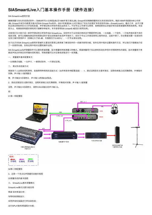
⼀、测量硬件基本配置单元⼀台便携式电脑,⼀台声卡,⼀套测试软件,⼀只测试话筒。
⼆、测试系统连接⽅式根据我个⼈运⽤经验和使⽤,我推荐两种常⽤的连接⽅式(当然有很多种配置连接): 1、测试话筒放在主要听⾳区,话筒和⾳箱之间⽆障碍物,环境相对安静。
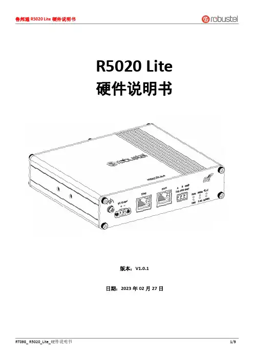
R5020Lite 硬件说明书版本:V1.0.1日期:2023年02月27日监管和认证类型表1:方针2011/65/EU欧洲RoHS2.02011/65/EU 指令是欧盟议会及欧盟委员会于2011年7月1日发布的指令,系在电子电气设备中限制使用某些有害物质的强制性标准。
2012/19/EU欧洲WEEE 2012/19/EU 指令是欧盟议会及欧盟委员会于2012年7月24日发布的指令,系关于报废电子电气设备的标准。
2013/56/EU欧洲2013/56/EU 指令是欧盟官方公报于2013年12月10日发布的电池指令。
本产品使用的纽扣电池符合2013/56/EU 指令标准。
表2:中华人民共和国电子行业标准SJ/T 11363-2006中华人民共和国电子行业标准SJ/T 11363-2006《电子信息产品中有毒有害物质的限量要求》由中华人民共和国信息产业部于2006年11月6日发布,规定了电子信息产品中含有毒有害物质的最大允许浓度。
请参照表3的概述,SJ/T 11363-2006规定了产品零件中的有毒、有害物质或元素的浓度不能超过规定的限度。
SJ/T 11364-2014中华人民共和国电子行业标准SJ/T 11364-2014《电子电气产品有害物质限制使用标识要求》由中华人民共和国工业和信息化部于2014年7月9日发布,规定了电子电气产品有害物质、环保使用期限、可否回收利用的标识要求。
本标准适用于中华人民共和国境内销售的电子电气产品,亦可供电子电气产品的物流过程参照使用。
鲁邦通产品使用下方橙色标志:表示其警示属性,即产品中含有某些有害物质,图例中间的“10”指电子信息产品环保使用期限Environment-friendly Use Period(EFUP)*为10年,在环保使用期限内可以放心使用,超过环保使用期限之后则应该进入回收循环系统。
*电子信息产品环保使用期限是指在正常使用的条件上,电子信息产品中含有的有毒、有害物质或元素不会发生外泄或突变并导致对环境造成严重污染或对人身、财产造成严重损害的期限。


EZ Series控制器连接说明书(硬件)SYNTECEZ Series控制器连接说明书(硬件)SYNTEC,2009/4版本:V1.0作者:修订日期:98/04/20前言本说明书详细地叙述了将EZ Series控制器的CNC 控制单元连接到机床上所需要的详细的电气和结构的规格。
本说明书给出了SYNTEC CNC通常使用的部件,如第2 章所示的安装尺寸图,并且给出了EZ4-T的接口定义。
相关的其他内容请参阅相应的说明书。
应用的系统型号本说明书适用的系统型号和它们的缩写为说明书的详细内容本说明书包含了从第1到第12章和附录相关的说明书下表列出了与SUPER控制系统相关的说明书。
在该表中,标有*的是本说明书。
注:如果还需要相关的技术支持,请访问新代公司主页有关伺服的说明书有关伺服放大器的说明书请参见各品牌伺服放大器的说明手册目录第一章 EZ Series控制器产品简介 (1)1.1 概述 (1)1.2新一代EZ Series数控系统规格 (3)第二章安装尺寸图以及接口定义图 (4)2.1 EZ 控制器安装尺寸图 (4)2.2 EZ控制器接口定义 (6)第三章安装 (7)3.1 安装环境 (7)3.1.1 电柜外部的环境要求 (7)3.2电源容量 (8)3.2.1 CNC 控制单元的电源容量 (8)3.3机床强电柜的设计和安装条件 (9)3.4电柜的温升设计 (10)3.4.1电柜内部的温升 (10)3.4.2使用热交换器进行散热 (10)3.5防止噪声干扰的方法 (11)3.5.1 信号线的分离 (11)3.5.2 接地 (12)3.5.3 控制单元的信号接地方法 (13)3.5.4 噪音抑制器 (14)第四章电源 (15)4.1本章主要叙述SYNTEC SUPER系列控制单元电源的连接方法。
(15)4.2控制单元的电源的接通与断开 (16)4.2.1控制单元的电源 (16)4.2.2外部24VDC输入电源及电路配置 (16)4.2.3电源的接通顺序 (17)4.2.4电源关断顺序 (18)4.3控制单元的电源连接电缆 (18)4.4 电池 (18)第五章 CNC与外围设备连接 (19)5.1 MDI键的排列 (19)5.2与I/O设备的连接 (20)5.2.1 概述 (20)5.2.2 与I/O设备接口的连接 (20)第六章主轴单元连接 (23)6.1变频主轴 (23)6.1.1 控制器联接埠定义 (23)6.1.2 变频主轴连接事例 (23)6.1.3 配线注意事项 (24)6.2伺服主轴 (25)6.2.1信号规格 (25)6.2.2变频器控制的伺服主轴 (26)6.2.3 伺服单元控制的伺服主轴 (27)第七章伺服单元连接 (28)7.1概述 (28)7.2伺服驱动器连接 (28)7.3输入输出信号规格 (29)7.3.1输入信号规格 (29)7.3.2编码器回授的信号规格 (29)7.4连接插头分布位置和插头定义 (30)7.5 与伺服放大器的连接 (31)7.5.1伺服放大器的连接示意图 (31)7.5.2几种常用伺服单元的连接 (32)第八章机床接口I/O的连接 (37)8.1概述:EMB IO分配简介 (37)8.2注意事项 (37)8.3 EMB的对外联机 (38)8.3.1 EMB的IO接口定义 (38)8.3.2各型号输入和输出端子台介绍 (41)8.3.3各型号输入和输出端子台与CNC连接举例 (48)第九章操作面板连接 (53)9.1概述 (53)9.2手轮连接图 (55)9.3启动停止按钮连接 (56)第十章急停 (57)第十一章以太网通讯 (58)11.1 概述 (58)11.2注意 (58)11.3网线的制作 (59)11.4控制器设置步骤 (60)11.5网络设定 (60)第一章EZ Series控制器产品简介1.1 概述4+1 轴或3+1 轴之最佳性价比控制器新概念CNC系统車床及铣床兩种系列32 bit CPU8 吋全彩液晶显示器前框工业防水设计内建开放式 PLC、MACRO实时断电资料储存最优化操作面板手持式手轮接口国际安规认证EtherNET、可热插入之 CF CARD 读卡机……稳定的产品效能EZ-Series 以全机完全无风扇设计、低发热的思考、以可靠度为设计第一考虑,整机完全模块化、将内部配线最精简化、控制器可靠度大为提升。


RG-NBS6002 交换机文档版本V1.1归档日期2022-06-23copyright © 2021 锐捷网络版权声明copyright © 2021 锐捷网络保留对本文档及本声明的一切权利。
未得到锐捷网络的书面许可,任何单位和个人不得以任何方式或形式对本文档的部分或全部内容进行复制、摘录、备份、修改、传播、翻译成其他语言、将其部分或全部用于商业用途。
、、和其他锐捷网络商标均为锐捷网络的商标。
本文档提及的其他所有商标或注册商标,由各自的所有人拥有。
免责声明您所购买的产品、服务或特性等应受商业合同和条款的约束,本文档中描述的部分或全部产品、服务或特性可能不在您的购买或使用范围之内。
除非合同另有约定,锐捷网络对本文档内容不做任何明示或默示的声明或保证。
由于产品版本升级或其他原因,本文档内容会不定期进行更新。
锐捷网络保留在没有任何通知或者提示的情况下对文档内容进行修改的权利。
本手册仅作为使用指导。
锐捷网络在编写本手册时已尽力保证其内容准确可靠,但并不确保手册内容完全没有错误或遗漏,本手册中的所有信息也不构成任何明示或暗示的担保。
前言读者对象本书适合下列人员阅读●网络工程师●技术推广人员●网络管理员技术支持●锐捷睿易官方网站:https:///●锐捷睿易在线客服:https:///?p=smb●锐捷网络官方网站服务与支持版块:https:///service.aspx●7天无休技术服务热线:4001-000-078●锐捷睿易技术论坛:/●常见问题搜索:https:///service/know.aspx●锐捷睿易技术支持与反馈信箱:*********************.cn●锐捷网络服务公众号:【锐捷服务】扫码关注本书约定1. 各类标志本书还采用各种醒目标志来表示在操作过程中应该特别注意的地方,这些标志的意义如下:危险表示重要安全操作指导。
在对设备进行操作时,应注意此类信息并了解放置发生意外的标准做法,否则可能会造成人身伤害。
Your ESP8266 is an impressive, low cost WiFi module suitable for adding WiFi functionality to an existing microcontroller project via a UART serial connection. The module can even be reprogrammed to act as a standalone WiFi connected device–just add power!The feature list is impressive and includes:802.11 b/g/n protocol Wi-Fi Direct (P2P), soft-APIntegrated TCP/IP protocol stackThis guide is designed to help you get started with your new WiFi module so let’s start!The hardware connections required to connect to the ESP8266 module are fairly straight-forward but there are a couple of important items to note related to power:The ESP8266 requires 3.3V power–do not power it with 5 volts!The ESP8266 needs to communicate via serial at 3.3V and does not have 5V tolerant inputs,so you need level conversion to communicate with a 5V microcontroller like most Arduinos use.However , if you’re adventurous and have no fear you can possibly get away with ignoring the second requirement. But nobody takes any responsibility for what happens if you do. :)Here are the connections available on the ESP8266 WiFi module:ESP8266 WiFi Module Quick Start GuideIntroductionHardware ConnectionsNOTE:Links and Code (Software) Supplied or Referenced in this Document is supplied as a service to our customers and accuracy is not guaranteed nor is it an Endorsement of any particular part, supplier or manufacturer. Use of information and suitability for any application is at users own discretion and user assumes all risk.All rights are retained by the AuthorWhen power is applied to the module you should see the red power light turn on and the blue serial indicator light flicker briefly.If you have a 3.3V FTDI Serial to USB board you can get started without fear of destroying your new ESP8266 WiFi module. Do note that many FTDI boards have a solder jumper to convert from 3.3V to 5V operation so ensure it is set to enable 3.3V operation.Here are the connections required to enable communication with the module over serial:With FTDI 3.3V Board (Legit)DO NOT DO THIS! You may break your Arduino or your ESP8266 WiFi module.This method is a bad idea for a number of reasons:The ESP8266 does not have 5V tolerant inputs–you could destroy your WiFi module.The ESP8266 may draw more current than the 3.3V regulator on your Arduino can supply–you could damage your Arduino.The operation of the ESP8266 outside of stated limits may be unstable and unreliable–you could damage your sanity.This method does have one redeeming feature:If you already have an Arduino Uno R3 it’s really easy to get started and (mostly) worked for me. :)We’re essentially going to use your Arduino as a power supply and USB to serial converter so you need to ensure there is no sketch that interferes with the serial connection. There are a couple of ways to achieve this:Upload an “empty” sketch that doesn’t use the serial connection, e.g. BareMinimum from theWith Arduino Uno R3 (Quick but not very legit)examples menu; or,Remove the microcontroller from the Arduino board (if it is a DIP form factor–don’t undersolder an SMD one).Here are the connections required to enable communication with the module over serial in this configuration:Serial ControlWith the hardware connections in place you can communicate with the WiFi module through a serial terminal.Using Arduino IDE Serial MonitorIf you already have the Arduino IDE installed the easiest way to get started is to use the built-in Serial Monitor:1. Plug in the WiFi module.2. Choose the correct serial port from the Tools > Serial Port menu.3. Open the Serial Monitor via the Tools menu or “magnifying glass” icon on the editor window.4. For the default firmware version (00160901), ensure Carriage return is selected in the lineending pop-up menu at the bottom of the serial monitor. (For later versions it must be set toBoth NL & CR.)5. For the default firmware version, ensure the communication speed is set to 115200 baud. (Forlater versions or if it has been modified it will need to be 9600 baud or similar.)You’re now ready to send your first commands!Using GNU ScreenIt’s possible to use GNU Screen out of the box with the default version of the firmware (00160901) which expects Carriage-Return-only line endings, e.g. (on OS X):screen /dev/bserial-AB12345 115200Unfortunately the updated firmware versions require Carriage-Return-and-New-Line line endings and there appears to be no way to configure screen to send both with one key press. Instead, you need to press <enter> or Ctrl-M then follow that with Ctrl-J.You might have more success with something like minicom or picocom with later firmware versions.Now you’re ready to send your first commands!First Commands1. Ensure AT commands are received correctly (the AT seems not to be case sensitive but therest of any command is case sensitive):ATResponse:OKIf you don’t get this response check:Hardware connections (the blue LED on the board should flash). Try swapping RX & TX.Correct baudrate–should be 115200 on the default firmware version (00160901).Correct line endings–should be Carriage Return only for default firmware version (00160901).If it still doesn’t work, give up, you’ve probably got better things to do with your life…2. Ensure the module is in a known state by issuing a reset command:AT+RSTResponse:ets Jan 8 2013,rst cause:4, boot mode:(3,6)wdt resetload 0x40100000, len 24444, room 16tail 12chksum 0xe0ho 0 tail 12 room 4load 0x3ffe8000, len 3168, room 12tail 4chksum 0x93load 0x3ffe8c60, len 4956, room 4tail 8chksum 0xbdcsum 0xbdreadyOr similar. The important part is the ready on the last line.3. Check the firmware version:AT+GMRThe stock firmware produces this output:001609014. Enable the module to act as both a “Station” and an “Access Point”:AT+CWMODE=3Response:OK(You may need to perform another reset after changing this setting.)5. List surrounding WiFi networks.First, if you’re on (at least) the 00160901 firmware you need to work around an apparent firmware bug that hangs on listing WiFi networks if the last joined network is no longer available.The following command ensures no network details are stored for connection (you should get an OK) response:AT+CWJAP="",""(You can check to see what the currently stored network details are with:AT+CWJAP?which should generate the following output if no network details are stored:+CWJAP:""With a later firmware or if the last joined network is still in the vicinity you shouldn’t need to do this pre-step.)Now you send the actual command to list networks in the vicinity:AT+CWLAPYou should get a response like:+CWLAP:(0,"",0)+CWLAP:(3,"WiFiArtThouRomeo",-80)+CWLAP:(3,"Free Public WiFi",-51)+CWLAP:(3,"Guest",-91)OKSometimes you might get ERROR or no response–in which case you’ll have to try doing the USB plug/unplug cycle and try again. (Or the same with the ground jumper.)6. Join a suitable WiFi access point:AT+CWJAP="<access_point_name>","<password>"You should get an OK response.For example, with the above list of access points you might use:AT+CWJAP="Guest","MyVoiceIsMyPasswordSoWhyDoINeedThis?"You can check if the module has been allocated a IP address with:AT+CIFSRYou should get your current IP address in response, e.g:192.168.1.2Acting as a TCP ClientYou can connect to an internet server (e.g. a web server) with the following method:1. Enable multiple connections (you need an OK response):AT+CIPMUX=12. Specify which connection channel you wish to connect on (0-4), the protocol type (TCP/UDP),the IP address (or domain if you have DNS access) and the port number using the CIPSTART command:AT+CIPSTART=4,"TCP","",80You should receive the response OK followed by Linked when the connection is open:OKLinked3. Next you need to specify how much data you wish to send (after specifying which channel). In thisexample we’re going to send “GET / HTTP/1.0\r\n\r\n” which is 18 bytes:AT+CIPSEND=4,18This time, instead of an “OK” response your will get a > prompt:>This indicates the module is waiting for you to send the 18 bytes of data.Here it gets a bit messy if you’re using the Arduino serial monitor as you have to swap between the line ending the module requires (“Carriage return” only) and what the HTTP server is expecting (“Both NL & CR”). Change the setting to Both NL & CR and send the following (you will need to press Send a second time to send the empty line the HTTP server expects):GET / HTTP/1.0The module should respond with:SEND OKNow you should change the line ending setting to Carriage return only so you can send additional commands.The module should provide a second response once the web server responds:+IPD,4,530:The 4 indicates it’s data from connection channel 4 and the 530 indicates there’s 530 bytes of data. You should now see the data:HTTP/1.0 302 FoundCache-Control: privateContent-Type: ...Woo! You just put a thing on the internet…time to go find a VC!You’ll likely get an OK response or two and then eventually an indication that the server has closed the connection:UnlinkActing as a TCP ServerYou can enable the module to accept TCP connections (i.e. act as a server) in the following manner:1. Connect to a WiFi access point.2. Enable multiple connections.AT+CIPMUX=13. Find out the IP address of the module:AT+CIFSRNote the response, e.g.:192.168.1.24. Set the module to listen (first parameter, mode is set to 1) for a connection on a specific port(in this case port 1336):AT+CIPSERVER=1,13365. From another device on the same network connect to the listening port, e.g. with telnet:telnet 192.168.1.2 1336The module should display:LinkType some text into the telnet session, e.g.:KiwiconAte!The module should display the following (0 being the connection channel, 13 being the length of the data received:+IPD,0,13:KiwiconAte!OKYou can send data in response with the CIPSEND command as used previously, e.g. (0 is the channel, 8 is the length of the data):AT+CIPSEND=0,8The module will display the prompt:>Then you can send the data, e.g.:WhatEvsAnd then the module will respond with:SEND OKThe telnet session should now display:WhatEvsYou can then end the telnet session with by pressing Ctrl-] and q<enter>, the module will display:UnlinkActing as a WiFi Access PointIn addition to connecting to WiFi Access Points the module can also act as an Access Point–this means you can connect devices to the module without any other network infrastructure in place. Ideal for a local private shared “drop box” perhaps…1. The module comes with an access point pre-defined (SSID of “ESP_…”) but you can define yourown with:AT+CWSAP="NoWorriESSID","password",3,0The first parameter is the SSID name; the second parameter is the password; the third the WiFichannel–pick one not used in your area; and, the final parameter is the encryption standard to use.An encryption value of 0 turns encryption off which means the password is ignored–but it still can’t be an empty value. I couldn’t get any encryption to work though (it would always create an unencrypted network) you might have more luck–possibly with a more recent firmware…2. To actually enable the network to be created you need to set the “WiFi mode” of the module to “AP”(2) or “Both” (3):AT+CWMODE=3Now you will be able to connect to your module as an access point from another device (e.g. a laptop or a phone).3. You can list the IP address etc of any device connected to the network with:AT+CWLIFWhich generates the response:192.168.4.100, [...]4. Now you can run the server example from above and connect–note that the module always has theIP 192.168.4.1 when acting as an AP.Updating the firmwareYou’ll be pleased to know you’re not stuck with the ample list of features that ship with your module, no, because you can update the firmware of your module! Yes, that means you can get new features & new bugs too…Finding New Official FirmwareIt’s not particularly easy to find new official firmware versions–the links are spread over forums, wikis and Google Drive accounts which don’t look particularly legit.It seems like the best source of details is the “Updates” section of the “Firmware” section on this page: /w/Wi07c#FirmwareThis ridiculous URL (from the link entitled “Find most upated firmware on this google link” on the above ElectroDragon page) seems to list all the official firmware updates: https:///folderview? id=0B3dUKfqzZnlwR2pVWjg3NXRVdW8&usp=drive_web&tid=0B3dUKfqzZnlwRjFaNTUzZFptbzg#listConsider uploading one of the following versions:ESP8266_flasher_V00170901_00_Cloud Update Ready.zipESP8266_AT_V00180902_02_baudrate watchdog added.zip(A note on version numbers: the version number 00160901 is made up of two parts: 0016 is theSDK version and 0901 is the AT command set version.)Once you’ve updated the firmware you also have the option of “Cloud Updates” but I’ve not managed to get any cloud update to work yet: /cloud-updating-your-wi07c-esp8266-now/Firmware Update ToolsWhile there are other tools for updating the firmware, for this example we’ll use esptoolhttps:///themadinventor/esptool/ which is cross platform and GPL licensed.Download the script file fromhttps:///themadinventor/esptool/master/esptool.py.Hardware Connections and Performing the UpdateIn order to update the firmware you need to configure the hardware to enter firmware update mode:1. Disconnect the module from your computer.2. Connect GPIO0 to ground (0 Volts) (“pulled low”) to enable firmware update mode.3. Reconnect the module to your computer.The module should now be in firmware update mode.(Note that the esptool docs say to ensure “GPIO2 is pulled high” but this doesn’t appear to be necessary.)Execute this command to perform the firmware update (the .bin file is from theESP8266_AT_V00180902_02_baudrate watchdog added.zip archive):python esptool.py --port /dev/bserial-ABC12345 write_flash 0x000000 " v0.9.2.2 AT Firmware.bin"You should receive progress updates during the upload process:Connecting...Erasing flash...Writing at 0x0007ec00... (100 %)Leaving...If you have problems connecting and have been using the Arduino IDE Serial Monitor ensure it isn’t open when trying to perform the upgrade. (Ask me how I know…)Once the update has completed:1. Disconnect the module from your computer.2. Remove the connection from GPIO0 to ground.3. Reconnect the module to your computer.You should now have a new firmware version installed and functioning.Note:The startup behaviour of the module is now different–it displays different output.The module now defaults to communicating at 9600 baud.The module now expects both carriage return and new line characters at the end of every line.New AT commands will be available and some bugs may have been fixed!Arduino and ESP8266Up until now you’ve been manually controlling the WiFI module via the serial console. It’s obviously possible to control the module programmatically via an Arduino sketch. At present there doesn’t seem like a “preferred” choice for an Arduino library to abstract the functionality but a few searches will find you Arduino examples to start with and presumably over time the Arduino community will settle on a preferred library.ESP8266 SDK and Custom FirmwareAn official Software Development Kit (SDK) has been released for the System-on-Chip (SoC) controller which powers the ESP8266 WiFi module. Using the SDK it’s possible to add extra features to the AT command firmware or even create a standalone firmware.Here’s a couple of custom firmwares to check out…NodeMcuLua based firmware for WiFi-SoC ESP8266: https:///nodemcu/nodemcu-firmwareVery cool and easy to get started with.Download the firmware:wget https:///nodemcu/nodemcu-firmware/raw/master/0.9.2/512k-flas h/nodemcu_512k.binFlash the firmware to the module:python esptool.py --port /dev/bserial-ABC123456 write_flash 0x000000 nodemcu_512k.binConnect to the module:screen /dev/bserial-ABC123456 9600Do the obvious…print("hello")For more details look at:https:///nodemcu/nodemcu-firmware#readmehttps:///nodemcu/nodemcu-firmware/wiki/nodemcu_api_enAT Command GPIO controlThere is a custom firmware with AT commands added to read and write the General PurposeInput/Output (GPIO) pins available–this enables you to control LEDs and read buttons with AT commands.For more details see: /esp8266-gpio-test-edited-firmware/More resourcesEspressif Systems (Designer): https:///en/products/esp8266/Espressif Systems Github: https:///espressifESP8266 Community Forum: /NURDspace on ESP8266: https://nurdspace.nl/ESP8266First setup of ESP8266 SDK: https://nurdspace.nl/ESP8266/First_setupElectroDragon on ESP8266: /w/Wi07cFinally…Have fun!Find updates to this guide and more information at /i/follower/p/notes-esp8266. This getting started guide is brought to you by Kiwicon 8 and !。
安全说明连接到供电网络。
有关如何处理的信息,请参见ACS530-01 硬件手册(3AXD50000727803 [ 中文])的电气安装一章。
连接动力电缆⏹接线图⏹电机电缆如图所示准备好电机电缆的两端。
图中为两种不同的电机电缆类型 a和b。
注意:将屏蔽线裸线做360 度接地。
⏹接线步骤(当选择ABB接线盒可选件时)1.在控制板旁粘贴当地语言的残余电压警告贴纸。
2.用螺丝刀松开夹子,卸下动力电缆端子上的盖板。
3.如图所示准备输入动力电缆和电机电缆。
注意:裸露屏蔽层需 360 度接地。
使用黄绿颜色将用屏蔽层制作的尾线标记为 PE 导线。
4.将电缆穿过下固定板上的孔,电机电缆向右,输入动力电缆向左。
5.连接电机电缆:•将屏蔽层在接地夹钳下进行 360 度接地。
•将电缆的屏蔽层连接到接地端子。
•把电缆的相导线连接到端子 T1/U、T2/V 和 T3/W。
6.按照步骤5使用端子 L1、L2 和 L3连接输入动力电缆。
7.安装控制电缆的接地架。
8.装回动力电缆端子上的盖板。
9.以机械方式紧固装置外部的电缆。
10.将电机端的电机电缆屏蔽层接地。
为最大程度降低射频干扰,请将电机电缆屏蔽层在电机端子盒的引线孔处进行 360度接地。
端子尺寸:R1…R9: 0.14…1.5 mm 2(所有端子)紧固力矩:0.5…0.6 N·m (0.4 lbf·ft)注:1)该信号源由外部供电。
参见制造商的的说明。
要使用由变频器辅助电压输出供电的传感器,请参阅变频器硬件手册 中“电气安装”一章的“两线制和三线制传感器的连接示例”一节。
2)对于控制电缆,在接地夹下方的接地架上对电缆的外屏蔽层进行 360 度接地。
3)出厂时已通过跳线连接。
4)注:对数字信号使用屏蔽双绞线。
安装可选模块(如果有)参见 ACS530-01 硬件手册(3AXD50000727803 [ 中文])的电气安装一章。
启动和使用要启动变频器,您需要设置电机数据、电机控制、连接宏和变频器参数。
硬件连接说明
注意,系统连接好通电后,若发现显示屏上某行或某些点处于超亮状态(即“亮线”),请立刻关闭显示屏电源并检查接线是否正确。
关电不及时有可能会烧坏显示屏行管,责任自负。
中帝威LED显示屏控制卡的连接基本相同,以30卡为例进行说明:30型控制卡:
一,控制卡和屏连接
新版控制卡的PCB上自带了08接口和12接口,板子为蓝色。
08接口通常接φ3、φ5等室内屏,12接口通常接P10、P16等户外屏。
08接口定义 12接口定义
接线前请认准接口,不要接错,不要接反。
否则可能烧屏、烧卡。
如果您的模组不是这2种接口,说明不适合我们的卡,请不要强行尝试。
二:卡和电脑的链接:
1,使用RS232接口是,要采用RS232交叉电缆,接线方法:
2,采用RS485接口的,RS485连接说明:
如果您购买的是普通卡,可以直接通过市面上的RS232->RS485无源转换器转为485接口。
连线如下:
则DB头的7为A+,8为B-,5为GND;
要和RS232转485的转换器相连接
多台显示器是并行连接的。
RS485接线的提示:
a)A+和B-信号应使用一对双绞线连接,如果您是用网线连接,一定要用
一组线中的2根连A+和B-。
否则将会有较大的干扰。
b)连接控制卡和RS485设备时,如果通讯不顺畅,可以尝试让2端共地
(即除了A+和B-外,还要把地线连在一起。
控制卡上5脚是地线),
共地时线一定要牢靠连接,并且够粗。
c)如果联网较多,或者线路较长,为了增强稳定性,可以尝试在总线末端
增加一个终端匹配电阻(120Ω,功率要大)。
d)可以尝试增加偏置电阻以改善通讯质量。
控制卡上已经预留焊盘,为
R5、R7。
电阻阻值可以根据经验确定。