克莱门特精密空调直膨安装手册-中文
- 格式:pdf
- 大小:4.73 MB
- 文档页数:59


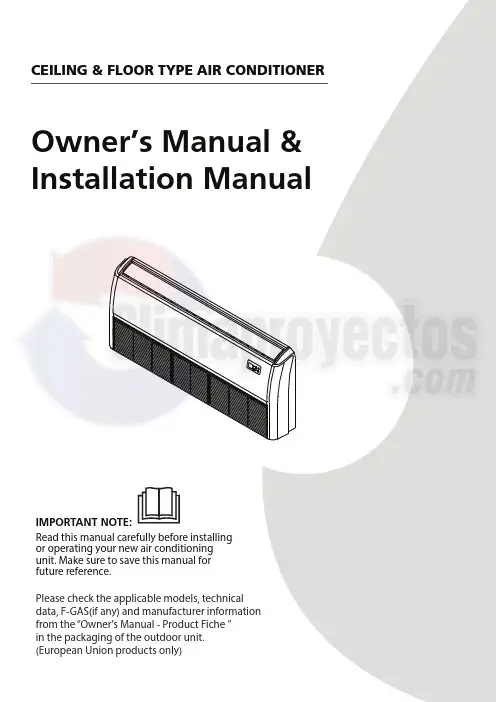
Owner’s Manual & Installation ManualIMPORTANT NOTE:Read this manual carefully before installing or operating your new air conditioning unit. Make sure to save this manual for future reference.Please check the applicable models, technical data, F-GAS(if any) and manufacturer information from the “Owner's Manual - Product Fiche ” in the packaging of the outdoor unit. (European Union products only)CEILING & FLOOR TYPE AIR CONDITIONEROwner’s ManualTable of ContentsSafety Precautions (04)Unit Specifications and Features 1. Indoor unit display 2. Operating temperature 3. Other features Care and Maintenance Troubleshooting (09)............................................................................................................................................................09...................................................................................................................................................11 .. (12)...................................................................13 (15)Installation ManualAccessories Installation Summary Unit Parts Indoor Unit Installation 1. Select installation location 2. Hang indoor unit 3. Drill wall hole for connective piping 4. Connect drain hose Outdoor Unit Installation 1. Select installation location 2. Install drain joint 3. Anchor outdoor unit Refrigerant Piping Connection A. Note on Pipe Length B. Connection Instructions –Refrigerant Piping 1. Cut pipe 2. Remove burrs 3. Flare pipe ends 4. Connect pipes Wiring 1. Outdoor Uint Wiring 2. Indoor Uint Wiring Air Evacuation 1. Evacuation Instructions 2. Note on Adding Refrigerant Test Run .....................................................................................18....................................................................19........................................................................................20.. (21)............................................................................................................................................21..............................................................................................................................................................23..........................................................................................................................25. (25) (26)...........................................................................................................................................26...............................................................................................................................................................27. (27) (28).....................................................................................................................................................28.. (29)..........................................................................................................................................................................29 ................................................................................................................................................................30............................................................................................................................................................30 (30) (32)........................................................................................................................................................33 (34) (37).................................................................................................................................................37.. (38) (39)Read Safety Precautions Before Operation and InstallationIncorrect installation due to ignoring instructions can cause serious damage or injury.This appliance is not intended for use by persons(including children) with reduced physical, sensoryor mental capabilities, or lack of experience and knowledge, unless they have been given supervision or instruction concerning use of the appliance by a person responsible for their safety. Children should be supervised to ensure that they do not play with the appliance(IEC Standard requirements).physical, sensory or mental capabilities or lack of experience and knowledge if they have been given supervision or instruction concerning use of the appliance in a safe way and understand the hazards involved. Children shall not play with the appliance. Cleaning and user maintenance shall not be made by children without supervision(EN Standard requirements).WARNINGS FOR PRODUCT USE• If an abnormal situation arises (like a burning smell), immediately turn o the unit and disconnect the power. Call your dealer for instructions to avoid electric shock, re or injury.• Do not insert fingers, rods or other objects into the air inlet or outlet. This may cause injury, since the fan may be rotating at high speeds.• Do not use flammable sprays such as hair spray, lacquer or paint near the unit. This may causefire or combustion.Safety Precautions④③ Page 4•Do not allow the air conditioner to operate for long periods of time with doors or windows open, or if the humidity is very high.ELECTRICAL WARNINGS• Only use the specified power cord. If the power cord is damaged, it must be replaced by the manufacturer , its service agent or similarly quali ed persons in order to avoid a hazard.• Keep power plug clean. Remove any dust or grime that accumulates on or around the plug. Dirty plugs can cause re or electric shock.• • • • •Do not pull power cord to unplug unit. Hold the plug firmly and pull it from the outlet. Pulling directly on the cord can damage it, which can lead to fire or electric shock.Do not modify the length of the power supply cord or use an extension cord to power the unit. Do not share the electrical outlet with other appliances. Improper or insu cient power supply can cause re or electrical shock.For all electrical work, follow all local and national wiring standards, regulations, and theInstallation Manual. Connect cables tightly, and clamp them securely to prevent external forces from damaging the terminal. Improper electrical connections can overheat and cause re, and may The product must be properly grounded at the time of installation, or electrical shock may occur. ④③ Page 56.serious injury and damage. 7.8.9.10.11.Do not turn on the power until all work has been completed.When moving or relocating the air conditioner, consult experienced service technicians for disconnection and reinstallation of the unit.How to install the appliance to its support, please read the information for details in "indoor unit installation" and "outdoor unit installation" sections .For units that have an auxiliary electric heater, do not install the unit within 1 meter (3 feet) of any combustible materials.Do not install the unit in a location that may be exposed to combustible gas leaks. If combustible gas accumulates around the unit, it may cause re.Install drainage piping according to the instructions in this manual. Improper drainage may cause water damage to your home and property.Note about Fluorinated Gasses(Not applicable to the unit using R290 Refrigerant) 1.This air-conditioning unit contains fluorinated greenhouse gasses. For speci c information on thetype of gas and the amount, please refer to the relevant label on the unit itself or the“Owner's Manual - Product Fiche ” in the packaging of the outdoor unit. (European ④③ Page 6where the room size corresponds to the room area as speci ec for operation.For R32 frigerant models:Appliance shall be installed, operated and stored in a room with a oor area larger than X m² . Appliance shall not be installed in an unvertilated space, if that space is smaller than X m² (Please see the following form).Reusable mechanical connectors and ared joints are not allowed indoors.(EN Standard Requirements).Mechanical connectors used indoors shall have a rate of not more than 3g/year at 25%of the maximum allowable pressure. When mechanical connectors are reused indoors,sealing parts shall be renewed. When ared joints are reused indoors, the are part shall be re-fabricated. (UL Standard Requirements)When mechanical connectors are reused indoors, sealing parts shall be renewed. When ared joints are reused indoors, the are part shall be re-fabricated. (IEC Standard Requirements)③ Page 7 ④>3.0 1.8m 9>3.0>48000>480000.6m80•Dispose of the appliance at designated municipal electronic waste collection facility.•When buying a new appliance, the retailer will take back the old appliance free of charge.•The manufacturer will take back the old appliance free of charge.•Sell the appliance to certi ed scrap metal dealers.Special noticeDisposing of this appliance in the forest or other natural surroundings endangers your health and is bad for the environment. Hazardous substances may leak into the ground water and enter the food chain.③ Page 8④Unit Specifications and Features Indoor unit displayAir inletDisplay panelAir outlet LouverInfrared receiverALARMDEF./FANMANUAL OPERATION TIMER(A)(B)(C)Infrared receiver(D)(E)(F)Infrared receiverMANUALALARMDEF./FANOPERATION TIMERInfrared receiverLED displayMANUAL TIMERALARMOPERATIONDEF./FANInfrared receiverMANUALTIMER ALARMOPERATION DEF./FAN Illustrations in this manual are for explanatory purposes. The actual shape of your indoor unit may be slightly di erent. The actual shape shall prevail.NOTE:Di erent models have di erent display panel. Not all the indicators describing below are available for the air conditioner you purchased. Please check the indoor display panel of the unit you purchased.This display panel on the indoor unit can be used to operate the unit in case the remote control has been misplaced or is out of batteries.③ Page 9 ④③ Page 10 ④ALARMDEF./FANDEF./FAN(G)(H)Infrared receiverLED displayMANUALInfrared receiverLED display• MANUAL button : This button selects the mode in the following order: AUTO, FORCED COOL, OFF .FORCED COOL mode : In FORCED COOL mode, the Operation light flashes. The system will then turn to AUTO after it has cooled with a high wind speed for 30 minutes. The remote control will be disabled during this operation.OFF mode : When the panel is turned OFF , the unit turns o and the remote control is re-enabled.• OPERATIONOPERATIONOperation indicator :• Timer indicator :TIMERTIMER• PRE-DEF indicator :(pre-heating/defrost)• Alarm indicator :• Func button :ALARMOperating temperatureWhen your air conditioner is used outside of the following temperature ranges, certain safety protection features may activate and cause the unit to disable.To further optimize the performance of your unit, do the following:• Keep doors and windows closed.• Limit energy usage by using TIMER ON and TIMER OFF functions.• Do not block air inlets or outlets.• Regularly inspect and clean air lters.NOTE: Room relative humidity less than 80%. If the air conditioner operates in excess of this gure, the surface of the air conditioner may attract condensation. Please sets the vertical air ow louver to its maximum angle (vertically to the oor), and set HIGH fan mode. Room Temperature17°C-32°C (62°F-90°F)0°C-30°C (32°F-86°F) 10°C-32°C (50°F-90°F)18°C-43°C (64°F-109°F) 11°C-43°C (52°F-109°F) -7°C-43°C (19°F-109°F) COOL modeHEAT modeDRY modeOutdoor Temperature(5°F - 75°F)(32°F - 122°F)0°C - 52°C (32°F - 126°F)(For specialtropical models)0°C - 52°C (32°F - 126°F)(For specialtropical models)(For models with low temp. cooling systems.)FOR OUTDOOR UNITS WITH AUXILIARY ELECTRIC HEATERInverter Split TypeFixed-speed TypeWhen outsidetemperature is below 0°C (32°F ), we strongly recommend keeping the unit plugged in at all time to ensure smooth ongoing performance.Default SettingWhen the air conditioner restarts after a power failure, it will default to the factory settings (AUTO mode, AUTO fan, 24°C (76°F)). This may cause inconsistencies on the remote control and unit panel. Use your remote control to update the status.Auto-Restart (some models)In case of power failure, the system will immediately stop. When power returns, the Operation light on the indoor unit will flash. To restart the unit, press the ON/OFF button on the remote control. If the system has an auto restart function, the unit will restart using the same settings. Louver Angle Memory Function(some models)Some models are designed with a louver angle memory function. When the unit restarts after a power failure, the angle of the horizontal louvers will automatically return to the previous position. The angle of the horizontal louver should not be set too small as condensation may form and drip into the machine. To reset the louver, press the manual button, which will reset the horizontal louver settings.Refrigerant Leak Detection System (some models)In the event of a refrigerant leak, the LCD screen will display “EC” and the LED indicator light will flash.Other featuresCare and MaintenanceCleaning Your Indoor UnitCleaning Your Air FilterA clogged air conditioner can reduce the cooling efficiency of your unit, and can also be bad for your health. Make sure to clean the filter once every two weeks.1.Open the air intake with a screwdriver or similar tool. Detach the grille from the main unit by holding the grille at a 45° angle,lifting it up slightly, and then pulling the grille forward.2. Take out the air lter. (applicable to 3.2~10.5KW air conditioners only).If using a vacuum cleaner, the inlet side should face the vacuum.If using water, the inlet side should face down and away from the water stream.6.Rinse the lter with clean water and allow it to air-dry. DO NOT let the lter dry in direct sunlight.7.Reinstall the lter.4.Remove the air lter.5.Clean the air lter by vacuuming the surface or washing it in warm water with mild detergent.3. Directly pull out the air lter from the air inlet as indicated (applicable to 14~16KW air conditioners only).Care and MaintenanceTurn o the unit and disconnect the power Remove batteries from remote controlMaintenance –Pre-Season InspectionAfter long periods of non-use, or before periods of frequent use, do the following:CAUTION• Any maintenance and cleaning of outdoorunit should be performed by an authorized dealer or a licensed service provider.• Any unit repairs should be performed by an authorized dealer or a licensed service provider.TroubleshootingCommon IssuesThe following problems are not a malfunction and in most situations will not require repairs.Issue Possible CausesUnit does not turn on when pressing ON/OFF button The Unit has a 3-minute protection feature that prevents the unit from overloading. The unit cannot be restarted within three minutes of being turned o .The unit may change its setting to prevent frost from forming on the unit. Once the temperature increases, the unit will start operating in the previously selected mode again.The set temperature has been reached, at which point the unit turns o the compressor. The unit will continue operating when the temperaturefluctuates again.TroubleshootingThe unit changes from COOL/HEAT mode to FAN mode Cooling and Heating Models: If the Operation light and PRE-DEF (Pre-heating/ Defrost) indicators are lit up, the outdoor temperature is too cold and the unit’s anti-cold wind is activated in order to defrost the unit.In Cooling-only Models: If the “Fan Only” indicator is lit up, the outdoor temperature is too cold and the unit’s anti-freeze protection is activated in order to defrost the unit.NOTE: If problem persists, contact a local dealer or your nearest customer service center. Provide them with a detailed description of the unit malfunction as well as your model number.TroubleshootingWhen troubles occur, please check the following points before contacting a repair company.Problem Possible Causes SolutionPoor Cooling Temperature setting may be higherthan ambient room temperature Lower the temperature settingThe heat exchanger on the indooror outdoor unit is dirtyClean the a ected heat exchangerThe air lter is dirty Remove the filter and clean it according toinstructionsThe air inlet or outlet of either Turn the unit o , remove the obstructionTroubleshootinghas entered the system. with refrigerant The compressor is broken Replace the compressor The voltage is too high or too lowInstall a manostat to regulate the voltagePoor heating performanceThe outdoor temperature is extremely lowUse auxiliary heating device Cold air is entering through doors and windows Make sure that all doors and windows are closed during use Low refrigerant due to leak or long-term useCheck for leaks, re-seal if necessary and top o refrigerantIndicator lamps continue flashing The unit may stop operation or continue to run safely. If the indicator lamps continue to flash or error codes appear, wait for about 10 NOTE: If your problem persists after performing the checks and diagnostics above,turn o your unit immediately and contact an authorized service center.System circuit is blockedDetermine which circuit is blocked and replace the malfunctioning piece of equipmentAccessoriesThe air conditioning system comes with the following accessories. Use all of the installation parts and accessories to install the air conditioner. Improper installation may result in water leakage, electrical shock and re, or cause the equipment to fail. The items are not included with the air conditioner must be purchased separately.Fixing screw for remote controller holder(some models ) Remote controller holder(some models )11111112Outlet pipe sheath (some models) Outlet pipe clasp (some models)Drain joint (some models)Seal ring(some models)Magnetic ring (wrap the electric wires S1 & S2 ( P & Q & E ) around the magnetic ring twice)(some models) Magnetic ring (Hitch it on the connective cable between indoor unit and outdoor unit after installation.)(some models) Conduit installation plate (some models)S1&S2(P&Q&E)Copper nut 2Varies by modelInstallation SummaryLN4567Evacuate the refrigeration systemConnect the wiresConnect the refrigerant pipesPerform a test runInstallation SummaryUnit PartsNOTE: The installation must be performed in accordance with the requirement of local and national standards. The installation may be slightly di erent in di erent areas.Unit PartsDisplay panel Drain pipeInstallation part Connecting pipe Air inlet Air outletRemote controller Air ow louver (at air outlet)Air inlet (with air lter in it)67885123456Indoor Unit InstallationInstallation Instructions – Indoor unitStep 1: Select installation location Before installing the indoor unit, you must choose an appropriate location. The following are standards that will help you choose an appropriate location for the unit.Proper installation locations meet the following standards:Indoor Unit InstallationRecommended distances between the indoor unitThe distance between the mounted indoor unit should meet the speci cations illlustrated in the following diagram.≥35mm≥1000m m≥ 35m m≥ 35m mNOTE:Panel installation should be performed after piping and wiring have been completed.☐ Enough room exists for installation andmaintenance.☐ Enough room exists for the connecting the pipe and drainpipe.☐ The ceiling is horizontal and its structure can sustain the weight of the indoor unit. ☐ The air inlet and outlet are not blocked.☐ The airflow can fill the entire room.☐ There is no direct radiation from heaters.DO NOT install unit in the followinglocations:Areas with oil drilling or frackingCoastal areas with high salt content in theairAreas with caustic gases in the air, such as hot springsAreas that experience power uctuations,such as factoriesEnclosed spaces, such as cabinetsKitchens that use natural gasAreas with strong electromagnetic wavesAreas that store flammable materials or gas Rooms with high humidity, such asbathrooms or laundry roomsIndoor UnitRefrigerant pipeconnection(D. gas side)Refrigerant pipeconnection(E. Liquid side)Drain pointHookACDEBIndoor parts installation sizeIndoor Unit InstallationCut o the roof beam.Strengthen the area at which the cut wasmade and consolidate the roof beam.Original concrete bricksSteel roof beam structureInstall and use the supporting steel angle.WoodPlace the wood mounting across the roof beam,then install the hanging screw bolts.New concrete bricksInlay or embed the screw bolts.(Blade shape insertion)(Slide insertion)Steel barEmbedding screw bolt(Pipe hanging and embedding screw bolt)1.Install and t pipes and wires after you havenished installing the main body.Whenchoosing where to start, determine thedirection of the pipes to be drawn out.Especially in cases where there is a ceilinginvolved, align the refrigerant pipes, drainpipes, and indoor and outdoor lines with theirconnection points before mounting the unit.2.The installation of hanging screw bolts.3.After the selection of the installation location,position the refrigerant pipes, drain pipes, andindoor and outdoor wires to the connectionpoints before mounting the machine.4.Drill 4 holes 10cm (4”) deep at the ceilinghook positions in the internal ceiling. Be sureto hold the drill at a 90° angle to the ceiling.5.Secure the bolt using the included washersand nuts.6.Install the four suspension bolts.7.Mount the indoor unit. You will need twopeople to lift and secure it. Insert suspensionbolts into the unit’s hanging holes. Fastenthem using the included washers and nuts.Step 2: Hang indoor unitInstall the hanging hook with expansiblebolt into the concrete to a depth of45~50mm to prevent loosening.Indoor Unit Installation8.Remove the side board and the grille.Screw nutWasherHanging screw boltOverhang partShockproof cushionNOTE: Con rm the minimum drain tilt is 1/100 ormore.9.Mount the indoor unit onto the hanging screw bolts with a block.Position the indoor unit on a at level by using a level to prevent leaks.Ceiling Installation20m mThe conduit installation plateSide boardscrews (not supply)Hanging arm Hanging screw boltWall-Mounted InstallationHow to install the conduit installation plate (if supplied)1. Fix the sheath connector (not supply) on the wire hole of the conduit installation plate.2. Fix the the conduit installation plate on the chassis of the unit.How to install the conduit installation plate (if supplied)1. Fix the sheath connector (not supply) on the wire hole of the conduit installation plate.Step 3: Drill wall hole for connective piping 1. Determine the location of the wall hole based on the location of the outdoor unit. 2. Using a 65mm (2.5in) or 90mm(3.54in)(depending on models )core drill, drill a hole in the wall. Make sure that the hole is drilled at a slight downward angle, so that the outdoor end of the hole is lower than the indoor end by about 12mm (0.5in). This will ensure proper water drainage. 3. Place the protective wall cu in the hole. This protects the edges of the hole and will help seal it when you nish the installation process.When drilling the wall hole, make sure to avoid wires, plumbing, and other sensitive components.WallIndoorOutdoor≈ 12mm / 0.5 inchIndoor Unit InstallationStep 4: Connect drain hoseNOTE ON DRAINPIPE INSTALLATION• When using an extended drainpipe, tighten the indoor connection with an additional protection tube to prevent it from pulling loose.• The drainpipe should slope downward at a gradient of at least 1/100 to prevent water from owing back into the air conditioner. • To prevent the pipe from sagging, space hanging wires every 1-1.5m (39-59”). • Incorrect installation could cause water to ow back into the unit and ood. The drainpipe is used to drain water away from the unit. Improper installation may cause unit and property damage.CAUTION•Insulate all piping to prevent condensation, which could lead to water damage. • If the drainpipe is bent or installed incorrectly, water may leak and cause a Indoor Drainpipe InstallationInstall the drainpipe as illustrated in the following Figure.1.2. Drainpipe connecting portDrain hosePipe claspInsulationCover the drainpipe with heat insulation to prevent condensation and leakage.Attach the mouth of the drain hose to the unit’s outlet pipe. Sheath the mouth of the hose and clip it rmly with a pipe clasp.Downward slope1/1001-1.5m (39-59”)NOTE: When connecting multiple drainpipes,install the pipes as illustrated in the followingFigure.≥10cm (4”)3.Pass the drain hose through the wall hole. Make sure the water drains to a safe locationOutdoor Unit Installation60c m(24i n)o n r i gh t200c m(79i n)i n fr o ntInstallation Instructions – Outdoor unitStep 1: Select installation locationBefore installing the outdoor unit, you mustchoose an appropriate location. The following arestandards that will help you choose an appropriatelocation for the unit.Proper installation locations meet thefollowing standards:☐Meets all spatial requirements shown inInstallation Space Requirements above.☐Good air circulation and ventilation☐Firm and solid—the location can support theunit and will not vibrate☐Noise from the unit will not disturb othersSPECIAL CONSIDERATIONS FOR EXTREMEWEATHERIf the unit is exposed to heavy wind:Install unit so that air outlet fan is at a 90°angle to the direction of the wind. If needed,build a barrier in front of the unit to protect itfrom extremely heavy winds.See Figures below.StrongwindStrong windIf the unit is frequently exposed to heavyrain or snow:Build a shelter above the unit to protectit from the rain or snow. Be careful not toobstruct air flow around the unit.If the unit is frequently exposed to salty air(seaside):Use outdoor unit that is specially designed toresist corrosion.Wind Baffle☐Protected from prolonged periods of directsunlight or rainNear a public street, crowded areas, orwhere noise from the unit will disturb othersNear animals or plants that will be harmedby hot air dischargeNear any source of combustible gasIn a location that is exposed to largeamounts of dustIn a location exposed to a excessive amountsof salty air☐Where snowfall is anticipated, raise theunit above the base pad to prevent icebuildup and coil damage. Mount the unithigh enough to be above the averageaccumulated area snowfall. The minimumheight must be 18 inches。
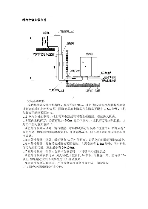
精密空调安装指引
1. 安装基本规格
1.1室内机组需安装主机脚架,高度约为300mm以上(如安装与高架地板配套则以高架地板的高度为依据),而脚架需加上脚掌且在脚掌下配有6.5mm胶垫,主机与脚架用螺丝紧固连接。
1.2 室内主机的铜管、排水管和电源线管可在主机底部,安放进入机内。
1.3室内主机前方,要留有最少700mm的工作空间。
(主机前方是回风位置,因此工作空间愈大愈好。
)
1.4室外冷凝器入风处,需与墙壁、障碍物或其它冷凝器(垂直式),最好应有1米的距离,如果因为实际环境限制,可以适度减少,但必须了解可能因此影响制冷效果。
1.5室外冷凝器出风处,最好要有4m的空间距离。
如受空间的限制可酌情减少.
1.6室外冷凝器,要有吊架或脚架紧固安装,且需安装有6.5mm胶垫。
同时避免直接与地面接触,离地最少有50-100mm。
1.7室外冷凝器,如在天台或平台安装时,不可破坏大楼防水层。
1.8室外冷凝器安装地点,最好不低于室内机5m以下,而且也不高于室内机15m 以上,如果超过此限必须事先与工厂确认联系。
1.9室外冷凝器安装地点,不可选择大楼最高位置安装,以防雷击。
1.10两台冷凝器可以竖直叠放。
本方案适用于:索克曼精密空调、世图兹精密空调、艾默生精密空调。
SUN ELECTRICINSTALLATION OVERVIEW:_____________________________________________The Installation Procedures listed are for the SUN KOOL KARE unit (EEAC104B for R-134a). The unit is shipped as a fully assembled unit, with the exception of the items listed in the Parts & Accessories List.PLEASE READ THESE INSTRUCTIONS COMPLETELY BEFORE SETTING UP UNITModel:SUN KOOL KARE EEAC104BR-134a UNIT SETUP Page:1 of 5Installation InstructionsINSTALLATION MUST BE PERFORMEDBYQUALIFIED SUN PERSONNEL ONLY!THIS UNIT MUST BE PLUGGED INTO A PROPER AC OUTLET FOR UNIT TO OPERATE CORRECTLY. REFER TO THE UNIT ID PLATE LOCATED ON BACK OF UNIT. EXTENSION CORDS ARE NOT RECOMMENDED,BUT IF AN EXTENSION CORD MUST BE USED, USE A CORD THAT IS LESS THAN 50 FEET WITH A 16 AWG, OR ABOVE 50 FEET AND LESS THAN 100 FEET WITH A 14 AWG.!USE STANDARD REFRIGERANT HANDLINGSAFETY PROCEDURES WHEN PERFORMING INSTALLATION ALWAYS WEAR SAFETY GOGGLES, DON’T SPILL OR TOUCH LIQUID REFRIGERANT, AVOID FLAMES, AND EXCESSIVE HEAT. USE ONLY IN WELL VENTILATED AREA.PART NUMBER DESCRIPTIONQTY EAH0001C02A Hose, 96” R-134a Blue 1EAH0001C01A Hose, 96” R-134a Red 1TEEAC104B Installation Instructions1EAK0027C00AS Kit, Vehicle Adapter O-Ring 1ZEEAC104B Users Manual 11585Bottle, Oil Charge 116826Screw, 8-32x31115080Adapter, Low Side Tank (For Virgin Tank to Low Side Adapter)107180108Holders, Hose (P-Clips)20647028707Adapter, Vehicle, High Side (Coupler)10647028708Adapter, Vehicle, Low Side (Coupler)10692191401MAC’s Form, Mail-In10692192801Product Registration Form 10692224201MAC’s Certification Form 14211000101Envelope10692229101Product & Warranty Registration 17009244701Recovery Tank Assembly1REQUIRED TOOLS:____________________________________________________• Screwdriver (Flat Blade and Phillips)• Safety Goggles (0001-5005)•Refrigerant Oil (Mineral) or Superlube (0681-0193-02 or -03)UNPACKING UNIT AND ACCESSORIES:___________________________________1. Cut Straps (A), and slide the carton (B) off the pallet (C).2. Remove the top of the carton (D), and packing foam (E)from unit. Split the corners of the base carton (F).3. Remove all boxes (G) and packing material (H) fromscale/tank compartment.4. Lean the unit (I) so it can be rolled off the base carton (F).5. Lean one side of unit (I) so packing foam (J) can beremoved. Repeat for other side.6. Inventory all items (G) using the Parts & Accessories listand inspect for damage.7. Discard scale guard (H).ACBDEF HGIJ FIGURE 1 UNIT PACKAGE1. Remove the Blue and Red Hoses from the accessories box and OIL the seals on each end.2. Connect the open end of the Blue and Red Hoses to the low and high side service portsrespectively on the backside of unit.3. Connect the Red and Blue adapters (0647028707 and 0647028708) to the Red and Blue Hosesfrom the service ports respectively.4. Remove the two P-Clip Hose Holders (07180108) and Screw (16826) from the accessories box.Slide the red and blue hoses through the p-clips. Using the supplied screw, mount both p-clips to the unit's back panel near the cord wrap.5. Place the O-Ring Kit (EAK0027C00AS) on top of unit.6. Remove the Oil Charge Bottle (1585) from the accessories box. Attach the oil charge bottle tothe port just below the power switch on front of unit. (Refer to the User’s Manual on operation of the Oil Charge feature.)7. Peel the backing from the User's Manual Envelope (4211000101) and apply the envelope, withthe open end on top, to either side of the unit, or in the location designated by the customer.8. Remove the User's Manual, and place the remainder of the documents in the envelope.BE SURE TO REVIEW THE USER'S MANUAL WITH THE CUSTOMER DURING TRAINING.9. Place the User's Manual in the Envelope.10. Remove Recovery Tank (7009244701) from its box. Remove cardboard wrap from RecoveryTank. Set on floor in front of unit.PREPARING NEW RECOVERY TANK:_____________________________________1. Referring to FIGURE 2, open the BLUE valve onRecovery Tank to release ALL COMPRESSED AIR.2. Remove the Particle Filter from the Recovery Tank.OIL seal. (BLUE VALVE)3. Attach Low Side Tank Adapter (115080) to the BLUEvalve of Recovery Tank. (DO NOT OVER TIGHTEN).4. Connect the BLUE service hose to the low side tankadapter. Open the vehicle adapter.5. Plug AC Cord to a 115VAC outlet. Turn unit on usingthe front power switch.FIGURE 2 RECOVERY TANK!THIS UNIT MUST BE PLUGGED IN TO A PROPER AC OUTLET FORUNIT TO OPERATE CORRECTLY. REFER TO UNIT ID PLATELOCATED ON BACK OF UNIT. EXTENSION CORDS ARE NOTRECOMMENDED, BUT IF AN EXTENSION CORD MUST BE USED, USEA CORD THAT IS LESS THAN 50 FEET WITH A 16 AWG, OR ABOVE 50FEET AND LESS THAN 100 FEET WITH A 14 AWG.PREPARING NEW RECOVERY TANK continued:6. Following the displays in FIGURE 3, to program a 10-minute vacuum time.7. Once completed, close Recovery Tank valve (BLUE) and remove Service Hose from RecoveryTank. Remove tank adapter.8. Replace the Particle Filter to the Recovery Tank. (BLUE SIDE)9. Place Recovery Tank on scale. Tank fittings should face straight out the back of unit. Connectvelcro strap and tighten belt.10. Remove bubble wrap from Red and Blue Hoses on unit near the recovery tank.11. OIL seals on the anti-blow back valves on Red and Blue Hoses from unit. Connect respectivelyto Recovery Tank. Refer to FIGURE 4YESSTARTING SCREENWill you Recyclefrom Vehicle this sequence?YESWill you be charging sequence?Will you be pulling a Vacuum this this sequence?Enter time to pull Vacuum on vehicle:Enter time to hold 10 minutes U PVacuum:00 minutes D O W NE N T E RN OYES N OYESN OU P D O W NE N T E R FIGURE 3 VACUUM MODEFIGURE 4 INSTALLING TANKCHARGING RECOVERY TANK:__________________________________________NOTE:THIS PROCEDURE IS USED TO SETUP THE UNIT FOR CHARGING. RECOVERY TANKSHOULD HAVE AT LEAST A 25” VACUUM. THIS PROCEDURE IS DONE WHEN RECOVERY TANK IS ON THE SCALE1. Be sure Recovery Tank valves (B) are closed.Refer to FIGURE 52. Disconnect the Red and Blue hoses from theRecovery Tank.3. Connect the low side tank adapter to the Red Valveon the Recovery Tank (B).4. Connect the blue service hose (C) (w/vehicleadapter) to the low side tank adapter. Open vehicle adapter.5. Connect the other end of the blue service hose tothe Virgin Tank (A). Raise the Virgin Tank to a higher level than the Recovery Tank.6. Open the Red Valve on the Recovery Tank.7. Invert the Virgin Tank (A) and open valve. Gravityand vacuum will transfer the liquid refrigerant to the Recovery Tank faster than reclaiming it.8. Press <AMOUNT> to display the amount ofrefrigerant that has been transferred.9. After the desired amount of refrigerant has beentransferred, close valves on Virgin Tank andRecovery Tank. Set Virgin Tank on ground upright.10. Disconnect the blue service hose from recoverytank. Disconnect the low side tank adapter fromrecovery tank. Connect adapter to low side service port on back of unit.11. Re-Oil seals on anti-blow back valves on Red and Blue Hoses from unit and connect toRecovery Tank. Open Recovery Tank valves.12. Connect the blue service hose to the service port. (This is a backward configuration than anormal operation.)13. Following the displays in FIGURE 6, perform arecover mode. This will reclaim the refrigerant from the hose. (Optional: Opening Virgin Tank valve will reclaim rest of refrigerant.)14. Once complete, disconnect the blue service hosefrom Virgin Tank and service port. Disconnect the low side tank adapter.15. Re-install the blue service hose correctly to theservice port.INSTALLATION COMPLETE/SETUP COMPLETEABCFIGURE 5 CHARGING TANK STARTING S C R E E NWill you Recycle from Vehicle this sequence?YESWill you be charging sequence?Will you be pulling a Vacuum this this sequence?N OYESN OYESN OFIGURE 6 RECOVER MODEREMEMBER TO OIL O-RINGS AND SEALS WHEN ATTACHING HOSES OR FITTINGS。
精密空调安装规范1. 引言精密空调是一种用于控制温度和湿度的空调系统,广泛应用于实验室、医院、计算机机房等环境。
由于其工作环境的特殊性,安装过程中需要严格遵守一定的规范,以确保系统的高效运行和安全性。
本文档将详细介绍精密空调的安装规范,以帮助安装人员正确安装和调试精密空调系统。
2. 安装环境准备在安装精密空调之前,需要对安装环境进行准备工作,以确保环境达到安装要求和系统正常运行的需求。
2.1 空调房间选择选择安装精密空调的房间时,应考虑以下因素:•房间的大小:房间应能容纳空调设备,并提供足够的空间用于维护和维修。
•房间的结构:房间应具备良好的防水、隔音和通风能力,以确保系统正常运行。
•房间的电力供应:房间应有足够的电力供应,以满足精密空调的运行需求。
2.2 空调设备选型根据实际需求和房间情况,选择适合的精密空调设备。
在选型时,应考虑以下因素:•制冷和制热能力:根据房间的大小和热负荷计算,确定空调设备的制冷和制热能力。
•能效比:选择具有较高能效比的空调设备,以降低能源消耗和运营成本。
•安全性能:确保所选设备符合相关的安全标准和规范要求。
3. 安装步骤3.1 安装位置选择根据精密空调的设计要求和实际情况,选择合适的安装位置。
在选择安装位置时,需要考虑以下因素:•空调设备的容量和大小,确保安装位置可以容纳设备。
•安装位置的通风情况,确保设备可以得到良好的空气流通。
•安装位置的便利性,方便设备的维护和维修。
3.2 安装工作准备在具体安装空调设备之前,需要进行以下准备工作:•准备好所需的工具和材料,包括螺丝刀、扳手、管件、密封材料等。
•确保安装人员具备相关的技术和安装经验。
•仔细阅读空调设备的安装说明书,了解具体的安装要求和步骤。
3.3 安装空调设备按照以下步骤安装空调设备:1.将空调设备放置在预定位置,并确保设备稳固。
2.连接空调设备的排水管道,以确保正常排水。
3.连接空调设备的冷却水管道,以提供制冷效果。

空调安装维修手册空调安装维修手册1.介绍本文档提供了空调的安装和维修指南,旨在帮助用户正确地安装和维护空调设备。
请仔细阅读本手册,并按照指导进行操作。
2.安装前准备2.1 安装位置选择- 选择位置时应避免阳光直射,周围不应有障碍物阻挡空气流通。
- 安装位置应放置在坚固且平整的墙面。
2.2 安全注意事项- 在进行安装之前,必须断开电源,并确保电源线不会受到损坏。
- 在操作过程中必须佩戴防护手套,以防触电或划伤。
3.安装步骤3.1 准备材料和工具- 空调机组- 冷凝器- 安装支架- 膨胀阀- 密封胶带- 螺丝刀和扳手3.2 安装空调机组- 将安装支架固定在墙上。
- 将空调机组安装在支架上,并使用螺丝固定好。
3.3 安装冷凝器- 将冷凝器放在合适的位置,并确保其与空调机组之间的连接线路不受阻碍。
- 使用螺丝将冷凝器固定在墙面上。
3.4 连接空调机组与冷凝器- 使用冷凝器的连接线缆将其与空调机组连接起来。
- 确保连接线缆牢固且没有松动。
4.维修与保养4.1 日常保养- 定期清洁空调机组和冷凝器表面,避免灰尘和污垢堆积。
- 清洁空调过滤网,以确保空气通畅。
4.2 故障排除- 当空调无法正常工作时,检查电源是否接通,以及电压是否正常。
- 如果空调有异常噪音,请检查有无松动的部件或有无进风口受阻。
附件:1.安装图示2.维修工具清单法律名词及注释:- 本文档涉及的法律名词解释仅供参考,不构成法律意见。
请根据实际情况咨询专业法律人士。
MANUAL DE INSTALACIÓNAIRE ACONDICIONADO TIPO INVERTERÍNDICEPRECAUCIONES DE SEGURIDAD (04)ESPECIFICACIONES Y ACCESORIOS (06)RESUMEN SOBRE LA INSTALACIÓN DE LA UNIDAD INTERIOR (07)PARTES DE LA UNIDAD (09)INSTALACIÓN DE LA UNIDAD INTERIOR (10)5.1 SELECCIÓN DE LA UBICACIÓN DE INSTALACIÓN (10)5.2 FIJAR EL SOPORTE DE PARED (11)5.3 PERFORAR LA PARED PARA COLOCAR LAS TUBERÍAS DE CONEXIÓN (12)5.4 PREPARACIÓN DE LA TUBERÍA DEL REFRIGERANTE (14)5.5 CONEXIÓN DE LA TUBERÍA DE DESCARGA (16)5.6 CONEXIÓN DEL CABLE DE COMUNICACIÓN (19)5.7 SUJECIÓN DE TUBERÍAS Y CABLES (21)5.8 MONTAJE DE LA UNIDAD INTERIOR (22)INSTALACIÓN DE LA UNIDAD EXTERIOR (24)6.1 SELECCIÓN DE LA UBICACIÓN DE INSTALACIÓN (24)6.2 INSTALACIÓN DE LA ARANDELA DE GOMA (26)6.3 FIJAR LA UNIDAD EXTERIOR (27)6.4 CONECTAR LOS CABLES DE COMUNICACIÓN Y DE ALIMENTACIÓN (28)INSTALACIÓN DE LA TUBERÍA DEL REFRIGERANTE (31)OBSERVACIONES SOBRE LA LONGITUD DE LA TUBERÍA (31)INSTRUCCIONES DE CONEXIÓN - TUBERÍA DEL REFRIGERANTE (31)7.1 CORTE DE TUBERÍAS (31)7.2 ELIMINACIÓN DE REBABAS (32)7.3 EXTREMOS ABOCARDADOS DE LA TUBERÍA (32)7.4 CONEXIÓN DE LAS TUBERÍAS (34)PURGA DE AIRE (37)INSTRUCCIONES SOBRE LA PURGA (37)OBSERVACIONES SOBRE LA CARGA DE REFRIGERANTE ADICIONAL (39)VERIFICACIONES ELÉCTRICAS Y DE FUGAS DE GAS (40)PRUEBA DE FUNCIONAMIENTO (41)ELIMINACIÓN DE RESIDUOS (43)SoporteFig. 3.11Si va a instalar una unidad sobre el suelo o sobre una plataforma de hormigón, realice lo siguiente:1. Marque las ubicaciones sobre la superficie para colocar cuatro pernos de anclaje para concreto según las especificaciones del cuadro de dimensiones para el montaje de la unidad.2. Realice una perforación para insertar los pernos.3. Limpie el polvo de los agujeros.4. Coloque una tuerca en el extremo de cada perno.5. Martille los pernos en los agujeros previamente perforados.6. Extraiga las tuercas de los pernos y coloque la unidad exterior sobre los pernos de anclaje.7. Coloque una arandela en perno, y luego las tuercas.8. Usando una llave, apriete cada tuerca hasta el tope.ADVERTENCIAAL PERFORAR EL HORMIGÓN, SE RECOMIENDA USAR SIEMPRE PROTECCIÓN OCULAR.Si va a instalar la unidad sobre un soporte de pared, realice lo siguiente:PRECAUCIÓNAntes de realizar la instalación de una unidad sobre la pared, asegúrese de que la pared esté hecha de ladrillos, hormigón o cualquier material de características similares. La pared debe ser capaz de soportar al menos cuatro veces el peso de la unidad.1. Marque las posiciones de los cuatro orificios del soporte , asegúrese que este cumpla con las especificaciones del cuadro de dimensiones para el montaje de la unidad.2. Realice una perforación para insertar los tornillos.3. Limpie el polvo después de realizar los agujeros.4. Coloque una arandela en el extremo de cada tornillo.5. Insertar los pernos de anclaje dentro de los agujeros realizados, coloque el soporte en su posición y golpee con un martillo los pernos en la pared.6. Compruebe que los soportes de montaje hayan quedado nivelados.7. Eleve la unidad cuidadosamente y coloque su base sobre los soportes.8. Atornille la unidad firmemente a los soportes.REDUCIR VIBRACIONES DE LA UNIDAD MONTADA EN LA PAREDSi es posible, puede instalar la unidad para pared con un soporte de caucho para reducir las vibraciones y el ruido.6.4: Conectar los cables de comunicación y de alimentaciónLa bornera de la unidad exterior está protegida por una tapa en el lateral de la unidad. En la parte interior de la tapa se encuentra impreso un diagrama eléctrico general.ANTES DE REALIZAR TRABAJOS ELÉCTRICOS, LEA ESTAS REGLAMENTACIONES1. La instalación eléctrica debe cumplir con las reglamentaciones locales y nacionales vigentesy debe ser llevada a cabo por personal calificado.2. Las conexiones eléctricas deben ser realizadas de acuerdo a las especificaciones delComprobaciones de fugas de gasHay dos métodos diferentes para comprobar si hay fugas de gas.Método de agua y jabónCon un cepillo suave aplique agua jabonosa o detergente líquido en todos los puntos de conexión de las tuberías en la unidad interior y exterior. La presencia de burbujas indica que hay una fuga.Método del detector de fugasSi usa un detector de fugas, consulte el manual de uso del dispositivo para un mejor funcionamiento.LUEGO DE COMPROBAR SI HAY FUGAS DE GASDespués de confirmar que todas las conexiones NO tienen fugas, reinstale la tapa de la válvula en la unidad exterior.PRUEBA DE FUNCIONAMIENTOAntes de llevar a cabo la prueba de funcionamientoSólo realice la prueba de funcionamiento después de haber completado los siguientes pasos:• Comprobaciones de seguridad eléctrica: Confirme que el sistema eléctrico de la unidad sea seguro y funcione.• Comprobaciones de fugas de gas: Compruebe todas las conexiones de la tuerca abocardada y confirme que el sistema no tenga fugas.• Verifique que las válvulas de gas y líquido (de alta y baja presión) estén completamente abiertas.Instrucciones sobre la prueba de funcionamientoLa prueba de funcionamiento se debe realizar durante al menos 30 minutos.1. Conecte la unidad a la electricidad.2. Pulse el botón ON/OFF en el control remoto para encender el equipo.3. Pulse el botón MODE (Modo) para desplazarse a través de las siguientes funciones, una por vez:COOL (refrigeración): Seleccione la temperatura más baja posible.HEAT (calefacción): Seleccione la temperatura más alta posible.4. Deje que cada función permanezca activa durante 5 minutos y lleve a cabo los siguientes chequeos:。
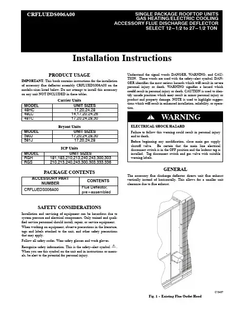
Installation InstructionsPRODUCT USAGEIMPORTANT :This book contains instructions for the installation of accessory flue deflector assembly CRFLUEDS006A00on the models--sizes listed below.Do not attempt to install this accessoryon any unit NOT INCLUDED in these tables.Carrier UnitsMODEL UNIT SIZES 48HC 17,20,24,2848LC 14,17,20,24,2648TC 17,20,24,28,30Bryant UnitsMODEL UNIT SIZES 580J 17,20,24,28,30581J 17,20,24,28ICP UnitsMODEL UNIT SIZESRGH 181,183,210,213,240,243,300,303RGS210,213,240,243,300,303,333,336PACKAGE CONTENTSACCESSORY PARTNUMBER CONTENTS CRFLUEDS006A00Flue Deflector,pre---assembledSAFETY CONSIDERATIONSInstallation and servicing of equipment can be hazardous due to system pressure and electrical components.Only trained and quali-fied service personnel should install,repair,or service equipment.When working on equipment,observe precautions in the literature,tags and labels attached to the unit,and other safety precautions that may apply.Follow all safety codes.Wear safety glasses and work gloves.Recognize safety information.This is the safety--alert symbol.When you see this symbol on the unit and in instructions or manu-als,be alert to the potential for personal injury.Understand the signal words DANGER,WARNING,and CAU-TION.These words are used with the safety--alert symbol.DAN-GER identifies the most serious hazards which will result in severe personal injury or death.WARNING signifies a hazard which could result in personal injury or death.CAUTION is used to iden-tify unsafe practices which may result in minor personal injury or product and property damage.NOTE is used to highlight sugges-tions which will result in enhanced installation,reliability,or opera-tion.GENERALThe accessory flue discharge deflector directs unit flue exhaust vertically instead of horizontally.This allows for a smaller unit clearance due to flue exhaust.C13437Fig.1--Existing Flue Outlet HoodINSTALLATION1.Close the manual shutoff valve on the gas supply piping.2.Shut off power to unit and install lockout tag.3.Remove existing flue hood from unit.Save screws.(SeeFig.1.)4.Align Deflector Assembly with outlet and remove screw incenter post that lines up with upper bracket.Save screw.SeeFig.2.5.Fasten Deflector Assembly inlet with screws removed inStep3to unit flue outlet.See.Fig.3.6.Align upper bracket with empty screw hole in center post.Secure with screw removed in Step4.See Fig.3.7.Return power to unit and remove lockout tag.8.Open the manual shutoff valve on the gas supply piping.SERVICERemove and clean the screen periodically to ensure proper airflow and heating efficiency.Inspect full length of flue stack for any blockages which could impair flue performance.Inspect every fall, and periodically during heatingseason.C13438Fig.2--Flue Deflector AssemblyShort ChassisT all ChassisC13439 Fig.3--Flue Discharge Deflector Installed on UnitCopyright2013CAC/BDP D7310W.Morris St.D Indianapolis,IN46231Edition Date:08/13 Manufacturer reserves the right to change,at any time,specifications and designs without notice and without obligations.Catalog No:IIK---CRFLUEDS06---01 Replaces:NEW2。

INSTALLATION MANUAL EKRTREKRTETS4PW56105-11Contents1. Introduction (2)2. Installation of EKRTETS as floor temperature sensor(only for floor heating/cooling applications) (3)3. Installation of the EKRTR (6)4. Setting up codes in the installer menu (14)5. T echnical characteristics (24)24PW56105-11.IntroductionThe room thermostat EKRTR can be used to control the Daikin system (radiator heating and floor heating/cooling applications).It is typically connected to the Daikin unit. Refer to the "T ypical application examples" in the Installation manual of the Daikin unit.■In case of floor heating-only applications the room thermostat can also be connected to the individual motorized valve of the floor heating loop.■If a floor heating-only application is used in combination with fan coil units each fan coil unit should have its dedicated fan coil thermostat.Optionally, an external temperature sensor EKRTETS can be connected to the thermostat and used as:■external ambient temperature sensor to control the room temperature (instead of the temperature sensor inside the thermostat). In that case, install the temperature sensor where you want to control the ambient temperature.■floor temperature sensor (only for floor heating/cooling applications) to protect the floor temperature or to prevent dew on the floor (in case of floor cooling). In that case, install the temperature sensor in the floor (refer to "Installation of EKRTETS as floor temperature sensor (only for floor heating/cooling applications)" on page 3).4PW56105-132.Installation of EKRTETS as floortemperature sensor (only for floor heating/ cooling applications)As it should be integrated into the floor, the installation of the temperature sensor EKRTETS should be planned and performed in advance.If EKRTETS is installed as floor temperature sensor, the thermostat EKRTR should be wall-mounted. Refer to "Wall-mounted installation" on page 6.1T ake the installation suggestions for the thermostat intoaccount when selecting the installation location.Refer to figure 3.2Integrate the EKRTETS temperature sensor in an electrical conduit (∅16 mm maximum) in the floor construction as shown below.Make sure to seal the temperature sensor electrical conduit to protect the thermostat from hot air currents and to allow the replacement of the temperature sensor.1Thermostat2T emperature sensor conduit (Ø16 mm maximum)3T emperature sensor EKRTETS (in conduit with seal)4Water pipes3Pass the temperature sensor cable through the conduit until it reaches the seal.44PW56105-14PW56105-154Connect the temperature sensor cable to the thermostat asdescribed in "Wall-mounted installation" on page 6.3.Installation of the EKRTRY ou can mount the EKRTR thermostat on the wall or use it as table-top model.3.1.Wall-mounted installationThe EKRTR thermostat can be wall-mounted, with supplied screws and plugs. Refer to figure 1.This is the case when you want to install the optional EKRTETS as external temperature sensor.1At the left of the thermostat, gently push the lid.2Remove the front cover by pulling it towards you.3Optionally for the EKRTETS, unscrew the screw of the cable holder in the bottom left corner of the back part of the thermostat and remove the transparent cable protection.4Remove the battery insulator.5Drill holes in the wall taking the dimensions of the thermostat into account and insert the supplied plugs in the holes.Refer to figure 4 (unit of measurement: mm).64PW56105-14PW56105-176Optionally, pass the temperature sensor wiring (EKRTETS)through the back of the thermostat and wire it as shown below.7Fasten the thermostat with the supplied screws.8Optionally for the EKRTETS, put the transparent cableprotection back into place and fix the cable protection with the screw.9Close the thermostat cover.10Remove the protective film from the LCD.3.2.Table-top installation of the thermostatOnly if the optional temperature sensorEKRTETS is not installed as externaltemperature sensor, the EKRTR can beused as a table-top model.In that case, no particular installationfor the thermostat is needed. Thethermostat functions as a completewireless unit and can be put anywherein the house into its table holder.Remove the battery insulator and the protective film from the LCD, as described in "Wall-mounted installation" on page 6.3.3.Installation of the receiverThe receiver needs to be installed indoors, typically close to the unit.84PW56105-1Keep the front clear at all times for access.1Drill holes in the wall taking the dimensions of the receiver into account and insert the supplied plugs in the holes.Refer to figure 5.2Fasten the receiver with the supplied screws.34Unscrew both screws of the lower right cable bracket and remove the bracket.5According your application, perform the wiring.For heating-only applications, wire connection to C is not to be installed.Use wire size 0.75~1.50 mm2.5b When connected to the motorized valve, wire the motorized valve and the receiver as shown below (for heating-only applications).The output relays (H and C are voltage-free contacts) can handle a maximum load of 4 A - 230 VAC.6Put the cable bracket back into place and tighten the screws.7Close the receiver cover and tighten the screws.Receiver-thermostat radio configurationY ou need to configure the radio connection between the receiver and the thermostat in order to make communication possible.1Put the receiver in radio configuration mode by pressing èduring 4 seconds.The ! LED lights up green and the receiver is now waiting for a thermostat configuration address.If needed, you can simply exit this mode by pressing èagain.2Send the configuration address by going to code 5® 03 (®ƒ ‡≈î‹)in the installer menu on the thermostat.Refer to “Setting up codes in the installer menu” on page 14.The thermostat will now send radio signals. On the LCD the icon j flashes.3Verify that the radio signals are correctly received by thereceiver.If the configuration is OK, the ! LED blinks green at each radio signal received from the thermostat.This also means that the receiver has left the radio configuration mode.4On the thermostat, exit the installer menu by pressing > tillthe "/" code is displayed and then pressing =.5Verify if the receiver is in thermostat mode and not in manualmode by checking if the è LED is off.Refer to "LED overview" on page 12.LED overviewManual controlY ou can use the receiver to manually override the heating or cooling command of the thermostat when for example the batteries of the EKRTR are empty or when the thermostat is broken. Manual control is activated when the èLED lights up yellow. In thermostat mode the è LED is off.è LED is offRed § LEDY ellow è LEDGreen § LEDY ellow è LED§ LED is offY ellow è LED4.Setting up codes in the installer menuY ou can set up codes, starting from the time and date menu (in advanced mode).1Activate the advanced mode by pushing > during 5seconds in OFF mode (D ).2Navigate to the date and clock setting menu (G ) by pressing>.3Press > and keep it pressed while now pressing =during 10 seconds.y is displayed next to 4®.4Press < or > to consult the current settings of the codes.5T o modify codes, press +, - or =.The value is flashing when being modified.6Press + or - to increase or decrease the code value by 1 step.T o put a code back to its default value, press + and - at the same time.7Press = to save your selection.Y ou can exit this code menu by going to the "/" code and pressing=.Refer also to "Overview of all codes" on page 18.4.1.Set-up for Fahrenheit degree typeRefer to the operation manual how to change parameter in user menu.4.3.Set-up floor temperature protection and dewprevention function (only for floor heating/coolingapplications)If EKRTETS is installed as floor temperature sensor it can be used to manage and thus protect the floor temperature. Refer to "Installation of EKRTETS as floor temperature sensor (only for floor heating/cooling applications)" on page 3. When this function is active the icon U flashes below the ambient temperature.In cooling mode, the dew prevention function will make sure there will be no condensation on the floor. The dew point is calculated based on room temperature and room humidity. When the floor temperature drops below the dew point the cooling demand will be temporarily stopped and the icon l is displayed.T o enable floor protection, set the following codes:4.4.Set-up for EKRTETS as external ambienttemperature sensorEKRTETS can be used as external ambient temperature sensor to control the room temperature (instead of the temperature sensor inside the thermostat). In that case, install the external temperature sensor where you want to control the ambient temperature.T o enable the function, set the following codes:4.6.Overview of all codesFollowing codes can be changed in the installer menu:4PW56105-119204PW56105-14PW56105-121224PW56105-14PW56105-123244PW56105-15.Technical characteristics5.1.EKRTR - Thermostat5.2.EKRTR - Receiver5.3.EKRTETS (optional)T emperature read out Steps of 0.1°C/0.1°F Operating temperature 0°C~50°C/32°F~122°F Setpoint temperature range4°C~37°C in steps of 0.5°C/39.5°F~99°F in steps of 0.5°F Electrical protection Class II - IP30 (indoor use, polution degree 2)Feeding and autonomy3 alkaline batteries AA.LR6 1.5 V approximately 2 years (depending on usage conditions)Operating temperature 0°C~50°C/32°F~122°FElectrical protection Class II - IP44 (indoor use, polution degree 2)Power supply 1N~50 Hz 230 VACRadio frequency and receiving zone433.92 MHz, <10 mW.Range of approximately 100 m in open space.Range of approximately 30 m in residential environment.Output relays Maximum load 4 A - 230 VAC Maximum fuse amp 3 APower consumption 15 W, maximum.Immunity against voltage surgesCategory III (2.5 kV)T ype of automatic action of the thermostat 1CExternal temperature sensorNTC 10K at 25°C/3 meter lead/NTC 10K at 77°F/3 meter leadNOTESC o p y r i g h t 2010D a i k i n4PW56105-1。
四管制冷热一体风冷热泵机组克莱门特尺寸-概述说明以及解释1.引言1.1 概述概述本文将详细介绍四管制冷热一体风冷热泵机组克莱门特尺寸。
随着环境保护意识的增强和能源消耗的不断上升,绿色环保节能技术得到了广泛应用和推广,其中冷热泵技术成为了一种受到关注的解决方案。
冷热泵机组通过逆向工作原理,能够实现冷热能的互相转换,从而在空调和供暖系统中提供高效能源利用。
在过去的几十年中,传统的冷热泵机组主要采用两管制结构,即分别配备冷水和热水管道,无法同时实现供冷和供热功能。
而四管制冷热一体风冷热泵机组的出现解决了这一问题。
它通过增加两个额外的管道,实现了供冷和供热同时进行的功能。
这不仅提高了能源利用效率,还减少了系统运行成本。
在论文的后半部分,将重点介绍克莱门特尺寸。
克莱门特尺寸是指冷热泵机组最重要的性能参数之一,它直接关系到机组的制冷和供热能力。
本文将通过详细分析克莱门特尺寸的组成和计算方法,探讨其在机组运行过程中的作用和影响。
通过本文的研究和分析,希望能够深入了解四管制冷热一体风冷热泵机组克莱门特尺寸的相关知识,并为相关领域的研究和应用提供一定的参考价值。
同时,也希望通过本文的介绍,能够引起更多人对冷热泵技术的关注和研究,推动其在环境保护和能源节约方面的进一步发展。
文章结构部分的内容如下:本文将分为以下几个部分来详细介绍四管制冷热一体风冷热泵机组克莱门特尺寸的相关内容:1. 引言1.1 概述:介绍四管制冷热一体风冷热泵机组的基本概念和原理,以及其在实际应用中的重要性和优势。
1.2 文章结构:本部分,将详细说明文章的结构和各部分的内容安排,以便读者能够更好地理解整个文章的逻辑关系和内容安排。
1.3 目的:明确本文的写作目的,阐述研究的重要性和意义,以及对相关领域的促进作用。
2. 正文2.1 管制冷热一体风冷热泵机组:详细介绍四管制冷热一体风冷热泵机组的工作原理、结构组成和关键技术特点,探讨其在制冷和供热领域的应用前景。
(本手册适用于直接膨胀风冷机组)资料版本V1.2归档时间20120601请妥善保管本手册以备参阅广东XXX电源技术股份有限公司版权所有,保留一切权利。
目录第一章 (1)第二章概述 (3)2.1 机房环境要求 (3)2.2 XXX系列机房专用精密空调 (4)第三章空调产品介绍 (5)3.1 机组外观 (5)3.2 型号说明 (6)3.2.1 室内机 (6)3.2.2 室外机 (6)3.3 机组结构组成 (7)3.3.1 机组部件 (7)3.3.2 智能控制系统 (10)3.3.3 机组其他功能 (11)第四章空调技术参数 (13)4.1 直接膨胀风冷式机组 (13)机组使用环境 (16)4.1.1 机组运行环境 (16)4.1.2 储藏环境 (16)第五章精密空调日常维护管理制度 (17)5.1 精密空调维护管理要求 (17)5.1.1 通信机房环境要求 (17)5.1.2 空调技术要求: (17)5.2 精密空调设备维护细则 (17)5.2.1 空气处理机的维护 (17)5.2.2 风冷冷凝器的维护 (17)5.2.3 制冷部分的维护 (18)5.2.4 加湿器部分的维修 (18)5.2.5 冷却系统的维护 (18)5.2.6 电气控制部分的维护 (18)5.2.7 整机工况检查 (18)5.2.8 专用空调设备的维护周期表 (18)5.3 精密空调控制操作流程 (19)5.3.1 温度设臵: (19)5.3.2 湿度设臵: (20)5.4 精密空调参数设臵规范 (20)第一章概述本章主要介绍数据中心机房特殊的环境要求和XXX机房恒温恒湿精密空调的特点、优势等内容。
1.1 机房环境要求精密的环境控制对计算机的运行非常重要,因此对机房的环境要求非常严格,这是为舒适性而设计的民用空调无法达到的,主要表现在以下几个方面:应用对象不同:机房专用空调就是为机房设备提供恒温恒湿的运行环境的,而民用空调都是直接服务于人的。
精密空调系统安装施工应用手册目录(一)勘测前准备: (1)(二)勘测: (1)(三)施工现场: (1)(四)工具及材料准备: (1)(五)工程材料: (2)(六)工程材料的外观检验及规格: (2)(七)开箱验货: (6)(八)机房空调设备安装: (7)(九)现场安装施工原则: (8)(十)安全作业原则: (9)(十一)设备安装原则: (11)(十二)底座的安装制作: (15)(十三)冷凝器安装原则: (16)(十四)电气安装原则: (17)(十五)冷凝水泵的安装(备选件) (17)(十六)冷媒管道的安装: (19)(十七)冷媒铜管钎焊: (22)(十八)压缩机控制阀操作: (25)(十九)系统气密检漏: (26)(二十)给、排水管道的连接: (27)(二十一)风管的安装: (30)(二十二)导流片安装要求: (32)(二十三)柔性管安装要求: (32)(二十四)止回阀安装要求: (33)(二十五)绝热层与保温钉安装要求: (33)(二十六)风管支、吊架安装要求: (33)(二十七)施工工艺基础知识: (34)(二十八)机械装联工艺: (34)(二十九)成组螺栓的安装: (35)(三十)接地端子的安装: (35)(三十一)电气装联工艺: (38)(三十二)接线原则: (38)(三十三)接线要求: (40)(一)勘测前准备:1、到现场勘测的工程师,必须清楚明白销售人员与用户所签订意向合同的内容。
2、室内外机组型号、数量,有无主备关系;备选项目;其他附带条款、事项。
3、工程师依据意向合同内容,根据现场勘测结果,初步核实机组的配置是否正确,合同有无遗漏事项。
4、带上勘测工具。
(二)勘测:1、设备安装前要对将要安装设备的环境作施工勘查,勘测过程中要认真、仔细(详细的勘测内容及方法,见附录一:勘测报告指导书)。
主要检查内容为:2、设备搬运环境:勘查空调设备搬运到安装现场环境,确定搬运类型,否则将影响到搬运成本。