德律风分机cs型
- 格式:doc
- 大小:3.90 MB
- 文档页数:57
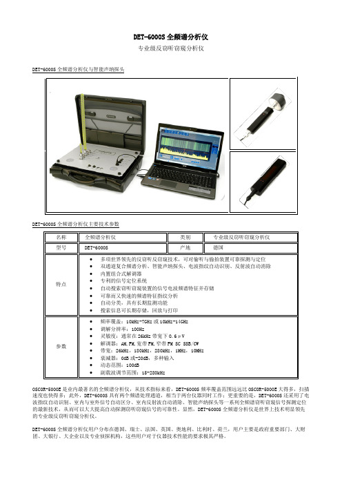
DET-6000S全频谱分析仪专业级反窃听窃窥分析仪 DET-6000S全频谱分析仪与智能声纳探头DET-6000S全频谱分析仪主要技术参数名称 全频谱分析仪 类别 专业级反窃听窃窥分析仪型号 DET-6000S 产地 德国特点∙多项世界领先的反窃听反窃窥技术,可对偷听与偷拍装置可靠探测与定位∙双通道复合频谱分析、智能声纳探头、电波指纹自动识别、反射波自动消除∙内置组合式解调器∙专利的信号定位系统∙自动搜索窃听窃窥装置的信号电波频谱特征并存储∙可靠而又快速的频谱特征指纹分析∙自动分类,具有长期监测功能∙搜索信息可长期存储,回放与打印参数∙频率覆盖:10kHz-7GHz或10kHz-14GHz∙调解分辨率:100Hz∙灵敏度:通常在26kHz带宽下0.6μV∙解调器:AM,FM,宽带FM,窄带FM SC SSB/CW∙带宽:26kHz,180kHz,280kHz,1MHz,10MHz∙衰减器:0dB或-20dB,多种输入∙动态范围:100dB∙副载波调节范围:15-280kHzOSCOR-5000E是业内最著名的全频谱分析仪,从技术指标来看,DET-6000S频率覆盖范围远远比OSCOR-5000E大得多,扫描速度也快得多;此外,DET-6000S具有两个频谱处理通道,相当于两台仪器同时工作;更重要的是,DET-6000S还采用了电波指纹自动识别、室内与室外信号自动区分、室内反射波自动消除、智能声纳探头等一系列全频谱窃听窃窥信号探测定位的最新技术,从而可以大大提高自动探测窃听窃窥信号的可靠性。
显然,DET-6000S全频谱分析仪是世界上技术明显领先的专业级反窃听窃窥分析仪。
DET-6000S全频谱分析仪用户分布在德国、瑞士、法国、英国、奥地利、比利时、荷兰,用户主要是政府重要部门、大财团、大银行、大企业以及专业侦探机构,这些用户对于仪器技术性能的要求极其严格。

由 授权东莞市利发爱尔空气净化系统有限公司芬兰设计服务热线:400 065 5199 制造中芬合资地址:广东省东莞市松山湖高新技术产业开发区工业东路2号International Ltd.IB-100-LAS350-01 V1.1使用本产品前请仔细阅读本使用说明书,并妥善保管LAS350 全智能烟气净化器本产品为针对商用场合设计,不完全适合家用前言① 开关及风速调整旋钮 长按 :开/关机旋转:手动模式下可调节风量大小, 并设置智能模式的最高风量② 模式切换键:长按3秒以上,可切换手动/智能模式 智能模式:蓝色LED点亮 手动模式:绿色LED点亮③ 出风口(四面均有)④ 电源接口⑤ 智能模式检测进风口重要安全信息· 请务必使用制造商标配的附件。
· 请确保不让儿童玩耍或使用机器,以防出现意外。
· 请勿堵塞进风口和出风口。
· 放置时保证机器平稳,禁止倾斜或放倒使用。
· 长时间不使用机器时,请拔掉插头。
· 请勿在温度变化较大的房间内使用本产品,因为这可 导致产品内部的冷凝。
· 请勿过度拧捏、弯曲或扭转交流电源线,否则线芯可能 会暴露在外或折断。
· 更换滤材、移动或清洁初滤网之前必须关掉电源并拔下 电源插头。
装箱清单1功能介绍2注:由于产品的更新和升级,操作可能会与说明书中所示的不符,请以实物为准。
感谢:首先感谢您选择LIFAair的产品!您即将享受到芬兰技术所带来的精湛、专业的体验。
· 请勿在浴室等高温、潮湿、会沾水的场所使用。
· 电源适配器内有电危险,请勿开盖,以免触电和影响保修。
· 请勿坐、靠本设备,否则有可能导致人受伤或设备破损等。
· 请勿将异物放入防护件、可移动部分、进风口和出风口中。
· 切勿将本产品直接放到空调下方,以防冷凝水滴到本产品上。
· 除专业维修人员外,其他人不得进行分解、维修,以免造成 火灾、触电、受伤。


LabVolt Series Datasheet Three-Way Pneumatic Control Valve with Digital Positioner (HART) - DVC 6200588376 (46955-E0)* The product images shown in this document are for illustration purposes; actual products may vary. Please refer to the Specifications section ofeach product/item for all details. Festo Didactic reserves the right to change product images and specifications at any time without notice.Festo Didactic en 120 V - 60 Hz 12/2023Three-Way Pneumatic Control Valve with Digital Positioner (HART) - DVC 6200, LabVolt SeriesTable of ContentsGeneral Description_________________________________________________________________________________3 Manual___________________________________________________________________________________________3 Table of Contents of the Manual(s)_____________________________________________________________________3Three-Way Pneumatic Control Valve with Digital Positioner (HART) - DVC 6200, LabVolt Series•••••••••••••General DescriptionThe Three-Way Control Valve is an industrial bronze control globe valve designed mainly for temperature control applications. This reliable valve features a durable construction, tight shutoff, and good control characteristics. The valve is designed to be used in mixing mode (two inlets, one outlet) and is of equalpercentage type. This valve is normally open on the lower port.Like the Control Valve, Model 46950-X, this model has either a pneumatic or an electric actuator and mayfeature options such as a digital valve controller (either a DVC 2000 or a DVC 6200) supporting either HART or Fieldbus, or a pneumatic positioner. Refer to the description of the equivalent 46950-X model for moreinformation.46955-0 Three-Way Pneumatic Control Valve with Digital Positioner (HART) - DVC 200046955-A Three-Way Pneumatic Control Valve with Positioner (Fisher 3660)46955-B Three-Way Pneumatic Control Valve 46955-C Three-Way Electric Control Valve 46955-D Three-Way Pneumatic Control Valve with Digital Positioner (FOUNDATION Fieldbus) - DVC 600046955-E Three-Way Pneumatic Control Valve with Digital Positioner (HART) - DVC 6000ManualDescription ManualnumberControl Valves (User Guide) __________________________________________________________585145 (86001-E0)Table of Contents of the Manual(s)Control Valves (User Guide) (585145 (86001-E0))1 Basic Control Valve Theory2 Basic Control Valve (46950-B)3 Pneumatic Control Valve with a Positioner (46950-A)4 Control Valve with DVC2000 (46950-0)5 Control Valve with DVC6000 – HART/FF (46950-E/-D)6 Control Valve with DVC6200 – HART/FF (46950-E/-D)7 Electric Control Valve (46950-C)Three-Way Pneumatic Control Valve with Digital Positioner (HART) - DVC 6200, LabVolt Series Reflecting the commitment of Festo Didactic to high quality standards in product, design, development, production, installation, and service, our manufacturing and distribution facility has received the ISO 9001 certification.Festo Didactic reserves the right to make product improvements at any time and without notice and is not responsible for typographical errors. Festo Didactic recognizes all product names used herein as trademarks or registered trademarks of their respective holders. © Festo Didactic Inc. 2023. All rights reserved.Festo Didactic SERechbergstrasse 373770 DenkendorfGermanyP. +49(0)711/3467-0F. +49(0)711/347-54-88500Festo Didactic Inc.607 Industrial Way WestEatontown, NJ 07724United StatesP. +1-732-938-2000F. +1-732-774-8573Festo Didactic Ltée/Ltd675 rue du CarboneQuébec QC G2N 2K7CanadaP. +1-418-849-1000F. +1-418-849-1666。

HAS4000系列八光热风发生机B2-2033-08(不附带控制器)使用说明书感谢您的购买使用之前请先阅读使用说明书。
阅读之后,为了日后使用,请务必妥善保管。
收到商品时,请检查以下项目・请确认铭牌,是否和订购产品相符。
・请确认运输过程中是否有破损,变形等。
・请确认螺丝和螺母是否有松动。
○前 言‥‥‥‥‥‥‥‥‥‥‥‥‥‥‥‥‥‥‥‥‥‥‥‥‥‥‥‥‥‥‥2○安 全 重要安全信息‥‥‥‥‥‥‥‥‥‥‥‥‥‥‥‥‥‥‥‥‥‥‥‥‥‥‥2 安全注意事项‥‥‥‥‥‥‥‥‥‥‥‥‥‥‥‥‥‥‥‥‥‥‥‥‥‥‥3○概 要 主要规格‥‥‥‥‥‥‥‥‥‥‥‥‥‥‥‥‥‥‥‥‥‥‥‥‥‥‥‥‥5 外形尺寸‥‥‥‥‥‥‥‥‥‥‥‥‥‥‥‥‥‥‥‥‥‥‥‥‥‥‥‥‥5○各部分名称 本 体‥‥‥‥‥‥‥‥‥‥‥‥‥‥‥‥‥‥‥‥‥‥‥‥‥‥‥‥‥‥6○安装设置 设置位置‥‥‥‥‥‥‥‥‥‥‥‥‥‥‥‥‥‥‥‥‥‥‥‥‥‥‥‥‥7 设 置‥‥‥‥‥‥‥‥‥‥‥‥‥‥‥‥‥‥‥‥‥‥‥‥‥‥‥‥‥‥7 本 体‥‥‥‥‥‥‥‥‥‥‥‥‥‥‥‥‥‥‥‥‥‥‥‥‥‥‥‥7 连接管‥‥‥‥‥‥‥‥‥‥‥‥‥‥‥‥‥‥‥‥‥‥‥‥‥‥‥‥‥8 风量调节‥‥‥‥‥‥‥‥‥‥‥‥‥‥‥‥‥‥‥‥‥‥‥‥‥‥‥9 电气配线 接线图‥‥‥‥‥‥‥‥‥‥‥‥‥‥‥‥‥‥‥‥‥‥‥‥‥‥‥‥10 接 线‥‥‥‥‥‥‥‥‥‥‥‥‥‥‥‥‥‥‥‥‥‥‥‥‥‥‥11○运 行 运 行‥‥‥‥‥‥‥‥‥‥‥‥‥‥‥‥‥‥‥‥‥‥‥‥‥‥‥‥‥12 停 止‥‥‥‥‥‥‥‥‥‥‥‥‥‥‥‥‥‥‥‥‥‥‥‥‥‥‥‥‥12○维护保养 日常检查・维护‥‥‥‥‥‥‥‥‥‥‥‥‥‥‥‥‥‥‥‥‥‥‥‥‥12 保 管‥‥‥‥‥‥‥‥‥‥‥‥‥‥‥‥‥‥‥‥‥‥‥‥‥‥‥‥‥12○故障对策‥‥‥‥‥‥‥‥‥‥‥‥‥‥‥‥‥‥‥‥‥‥‥‥‥‥‥‥‥13○资 料‥‥‥‥‥‥‥‥‥‥‥‥‥‥‥‥‥‥‥‥‥‥‥‥‥‥‥‥‥‥14○售后服务‥‥‥‥‥‥‥‥‥‥‥‥‥‥‥‥‥‥‥‥‥‥‥‥‥‥‥‥底封面12重要安全信息本书对八光热风发生机「HAS4000 系列」的设置、操作、检查以及维护的方法进行了说明。
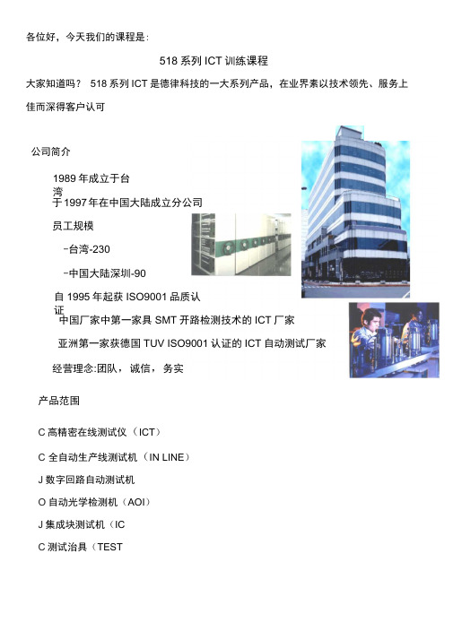
各位好,今天我们的课程是:518系列ICT训练课程大家知道吗?518系列ICT是德律科技的一大系列产品,在业界素以技术领先、服务上佳而深得客户认可公司简介1989年成立于台湾于1997年在中国大陆成立分公司员工规模-台湾-230-中国大陆深圳-90自1995年起获ISO9001品质认证中国厂家中第一家具SMT开路检测技术的ICT厂家亚洲第一家获德国TUV ISO9001认证的ICT自动测试厂家经营理念:团队,诚信,务实产品范围C高精密在线测试仪(ICT)C 全自动生产线测试机(IN LINE)J数字回路自动测试机O自动光学检测机(AOI)J集成块测试机(ICC测试治具(TEST2. TR-518F1992 年推出, CMOS+Armature Relay 3. TR-518FR(1996 年推出, Reed Relay 开关,方便稳定,德律首创之 ICT)创新技术,功能大辐提升,速度较 518快一倍,台湾精品奖)整合功能量测,功能强大,速度更较 518F 快一倍,台湾精品奖)的完美应用,超强功能,速度较 518F 快一倍以上,台湾精品奖)_TR-518FR =m a518 系列 ICT 又分以下 4 款:1. TR-518 (1989 年推出, CMOS 切换开关,性能 4. TR-518FE1996 年推出, CMOS+Armature RelayICT的概念1. 何谓ICT ?ICT即在线测试仪(In Circuit Tester),是一大堆高级电表的组合。
电表能测到,ICT就能测到,电表测不到,ICT可能也测不到。
例如:R//Jumper,则R无法用电表测出,而ICT也测不出。
2. ICT能测些什么?Ope n/Short,R,L,C 及PN 结(含二极管,三极管,Zen er,IC)3. ICT与电表有何差异?ICT可对旁路组件进行隔离(Guardi ng),而电表不可以。
所以电表测不到,ICT可能测得到。
收音机史话|有一种情怀叫作“德律风根”收音机史话|有一种情怀叫作“德律风根”2016-12-26 无线电杂志|田浩北纬21度收音机北纬21度收音机微信号L21-Radio 功能介绍让互联网延续收音机情怀。
让更多人热爱广播、喜欢收音机,了解收音机与广播的最新动态,感受收音机文化。
本文转自《无线电》杂志的公众号“无线电杂志”。
本来是上、下两篇,我为了方便大家阅读,整合成了一篇,感谢“无线电杂志”公众号小编的同意。
北纬21度收音机,2016年12月27日上两期内容:解密北平从未暴露的3个红色电台|冬至,我们的机油“拖后.前卫”与新闻主播一起包暖心饺子!作者|田浩Telefunken(德律风根),是20世纪初,德意志仍处于帝国时代时,两家最强大民族企业联合的结晶。
这位贵族后裔继承了两大前辈雍容华贵的气质,成长中又不时闪现出青春才子特有的机灵和活力。
Telefunken坚守着严谨认真的价值观,既不遗余力地创造出诠释高贵的世界顶级作品,也热情地推出适合于广大民众的质量上乘之作。
在每款Telefunken流传于世的经典产品上,在电子管灯丝缓缓亮起洒落四周的暖光里,在低频宛如天鹅绒般厚重、高频仿佛丝绸般轻柔通透的音质中,听者会感觉到庄严神圣的美、朝气蓬勃的青春和热情洋溢的创造力缓慢却不可抗拒地渗入自己的灵魂。
沉浸于如幻似梦的感觉,恍惚间整个世界都小心翼翼,不敢用任何突兀的事情来惊扰这由沉淀了上百年的风云往事所酝酿成的时刻——聆听Telefunken的时刻。
显赫家世,坎坷起步:1903-192319世纪和20世纪交替之时,德国有两家著名的电气公司同时承办无线电报的业务。
其中之一是至今仍大名鼎鼎的Siemens(西门子)公司,它由德意志贵族E. Werner von Siemens(E·维尔纳·冯·西门子,1816-1892)以电机专利在19世纪中期起步,在20世纪初已经成为全球范围内电气工业的先驱。
SSC161.05UTFor pressure independent zone valves, small globe valves and 3-party valves●Operating voltage AC/DC 24 V, positioning signal DC 0...10 V●Self calibrating to the valve stroke●Direct mounting with coupling nut, no tools required●Manually override●Position and actuator motion indication (LED)●Positioning force 300 N●Parallel operation of multiple actuators possibleA6V13359035_en--_c Smart Infrastructure 2023-07-052 SiemensA6V13359035_en--_cSmart Infrastructure2023-07-05● For zone valves VVP.., VXP.., VMP..: compatible with SSC161.05UT ● For 2-/3-port valves: compatible with SSC161.05UT● Typically in chilled ceiling, VAV and fan coil unit applications●Max.10 units of SC161.05UT can operate in parallel, provided the controller output suffices.When the actuator is driven by DC 0…10 V positioning signal, it produces a stroke, which is transmitted to the valve stem.DC 0…10 V positioning signal● The valve opens / closes in proportion to thepositioning signal at Y.● At DC 0 V, actuator stem is retracted, the normallyclosed valve is fully closed.● When there is no operating voltage, the actuatormaintains its current position.● This actuator provides a DC 0…10 V positionfeedback signal proportional to the stroke of the actuator stem.Y = Positioning signal Y [V]H = Percentage of calibrated valve strokeLED indicationFlashing green in sequence: LED1-->LED2-->LED3 (500 ms each)3SiemensA6V13359035_en--_cSmart Infrastructure2023-07-05OrderingWhen ordering, specify both type and quantity. Example:DeliveryValves and actuators must be ordered separately. For easier valve assembly, actuators ordered separately have the actuator stem fully retracted.Equipment combinationsCombinable valves1)With ASK30 mounting kitNote: To ensure trouble-free operation of third-party valves with the actuator, the valves must satisfy the following requirements:● Threaded connections with coupling nut: ¾” ● Nominal force: > 300 N ● Dimension X ≥ 8.8 mm ● Dimension Y ≤ 14.3 mmControllersCombinable room thermostatsRelated documents such as the environmental declarations, declarations of conformity, etc.,can be downloaded from the following Internet address:/bt/downloadEngineeringThe actuators must be electrically connected in accordance with local regulations (see"Connection diagram [▶ 12]").Observe permissible temperatures (see "Technical data [▶ 9]").4Siemens A6V13359035_en--_c Smart Infrastructure 2023-07-055SiemensA6V13359035_en--_cSmart Infrastructure2023-07-05MountingValve and actuator are easy to assemble on site before commissioning: ● Remove protective cover from the valve body.● Position the actuator and tighten the union nut manually.●See "Mounting instruction" for graphical instructions.OrientationInstallation● Observe all admissible temperatures (see "Technical data [▶ 9]").● Do not twist the cable.● Magnets can damage the actuator.● Provide a means for isolation from the power supply, e.g., connecting a circuit breaker orswitch fuse upstream of the control unit.6 SiemensA6V13359035_en--_cSmart Infrastructure2023-07-05CommissioningWhen commissioning, check both wiring and functioning of the actuator.● Actuator stem extends Normally open valve closes, normally closed valve opens ● Actuator stem retracts Normally open valve opens, normally closed valve closesSelf-calibrationWhen operating voltage is applied, the actuator self-calibrates (fully retracted ➙ fully extended ➙ setpoint).OnFully retracted7SiemensA6V13359035_en--_cSmart Infrastructure2023-07-05Manual operationA 3-mm Allen wrench can be used to move the actuator to any position. To move the actuator stem manually 1. Open the cover using a proper screwdriver.2. Press and hold down button (a) illustrated below for at least three seconds.– The actuator ignores any positioning signal from the controller.3. Adjust the position of the actuator stem by rotating Allen wrench (b) illustrated belowclockwise or anti-clockwise.– The actuator stem moves down if you rotate clockwise; it moves up if you rotate anti-clockwise. The manually set position is retained. 4. To exit manual operation mode, press and hold down button (a) illustrated below againfor at least three seconds.– The actuator runs a self-calibration automatically. Positioning signal sent from the controller takes effect. 5. Close the cover.Cabling operation1. Unscrew cover screw2. Remove cover3. Connect or disconnect wire terminals4. Install the cover5. Screw in the cover screwA 6V 13359034Z 00MaintenanceThe actuators require no maintenance.DisposalWarrantyTechnical data on specific applications are valid only together with Siemens products listedunder "Equipment combinations". Siemens rejects any and all warranties in the event thatthird-party products are used.Open Source Software (OSS)Software license overviewThese devices use Open Source Software (OSS). All Open Source Software componentsused in the product (to include copyrights and licensing agreement) are available at/bt/download.8Siemens A6V13359035_en--_c Smart Infrastructure 2023-07-051) Provided that the controller output is sufficient.9 Siemens A6V13359035_en--_c Smart Infrastructure 2023-07-05FCC regulationsModification of this device to receive cellular radio telephone service signals is pro-hibited under FCC rules and federal law.This equipment has been tested and found to comply with the limits for a Class B digitaldevice, pursuant to part 15 of the FCC Rules. These limits are designed to providereasonable protection against harmful interference in a residential installation. Thisequipment generates, uses and can radiate radio frequency energy and, if not installed andused in accordance with the instructions, may cause harmful interference to radiocommunications. However, there is no guarantee that interference will not occur in aparticular installation. If this equipment does cause harmful interference to radio or televisionreception, which can be determined by turning the equipment off and on, the user isencouraged to try to correct the interference by one or more of the following measures:Reorient or relocate the receiving antenna.Increase the separation between the equipment and receiver.Connect the equipment into an outlet on a circuit different from that to which the receiver isconnected.Consult the dealer or an experienced radio/TV technician for help.Changes or modifications not expressly approved by the party responsible for compliancecould void the user’s authority to operate the equipment.StatementThis device complies with part 15 of the FCC Rules. Operation is subject to the following twoconditions: (1) This device may not cause harmful interference, and (2) this device mustaccept any interference received, including interference that may cause undesired operation.10Siemens A6V13359035_en--_c Smart Infrastructure 2023-07-0511 Siemens A6V13359035_en--_c Smart Infrastructure 2023-07-0512 SiemensA6V13359035_en--_cSmart Infrastructure2023-07-05Connection terminalsG System potential (AC/DC 24 V) G0 System neutralY Positioning signal DC 0…10 V U Feedback signal MMeasurement referenceConnection diagramN = ControllerSP, G = System potential AC 24 VSN, G0 = System neutralY = Positioning signal U = Feedback signal M = Measurement reference13SiemensA6V13359035_en--_cSmart Infrastructure2023-07-05mm。