ICEM六面体网格划分
- 格式:ppt
- 大小:4.64 MB
- 文档页数:60
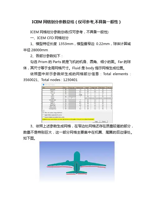
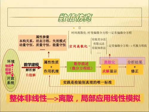
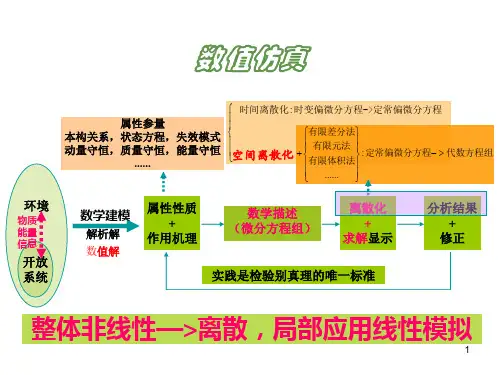
ICEM网格划分参数总结(仅可参考,不具备一般性)ICEM网格划分参数总结(仅可参考,不具备一般性)一、ICEM CFD网格划分1、模型特征长度1353mm,模型最窄边0.22mm,球体计算域半径28000mm2、各部分参数如下:勾选Prism的Parts就是飞机的机身、圆角、细小的面。
Far的球体,其尺寸等于全局网格尺寸。
Fluid 是body指示网格生成位置。
依照图中所示参数所生成的网格部分信息:T otal elements : 3560021、Total nodes : 12304013、依照上述参数生成网格,在窄边处网格还存在质量较差的部分,数量不是特别巨大,这一部分网格主要集中在机翼、尾翼的后边缘处。
如下图。
二、Fluent求解1、General:Pressure-Based,Absolute Velocity Formulation,Time steady2、Models:开启能量方程、k-e-RNG湍流模型3、Materials:选择理想气体4、边界条件:将球体计算域far设置为压力远场,马赫数0.75,根据需要调整了风速方向(目前仅尝试了alpha=-5~15、beta=-25,21组实验),温度设定223K。
operating condition中operating pressure设定为26412Pa5、参考值:compute from 球体计算域。
参考面积设置为机翼迎风面积0.20762m^2(参考面积这一部分不知道对不对)6、Solution methods:coupled7、Solution controls:库朗数设置为68、初始化:Hybrid Initialization目前对飞机模型进行了修改,根据上述参数重新划分网格,再次调整风速方向进行了2次计算,还能够收敛。
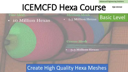
Advanced Engineering Solutions ICEMCFD Hexa Course Sijal AhmedBasic Level Create High Quality Hexa MeshesLecture 3 : Hexa MeshingSee DemoVertexEdgeFaceBlockPointCurveSurfaceVolume•Vertex color coding–Red →Point –Green →Curve –Black →Surface –Cyne →Internal•Edge color coding–Green →Curve –Black →Surface –Cyan →InternalCreate Block•3d bounding box •2d surface blocking •2d planner•3D block from vertices/faces ▪Hexa▪Quarter O-grid▪Degenerate or prism •2D block from verticesDegenerate or prism from 6 verticesQuarter O-grid from 6 verticesHexa from 8 verticesHexa from two facesExtrude Face(s)•Interactive•Select face and MMB whereyou want block•Fixed distance•Specify distance in normaldirection•Along the curve•Select curve and its endwhere you want to end theblockNumber of layers = 530 deg twist2d to 3d blocking •Translation•Rotation✓Choose origin✓Choose axis✓You can also create newparts from points and curvesAssociation•Vertex to point, curve or surface.•Edge to curve or surface.•Face to surface or part.•Edge color coding–Green →Curve –Black →Surface –Cyan →Internal•Vertex color coding–Red →Point –Green →Curve –Black →Surface –Cyne →InternalAll edges are associatedNo AssociationEach edge is associatedto corresponding curveO-GridFull O-GridMesh qualityHow to create O-gridFull O-gridHalf O-gridQuarter O-gridMerge VerticesPropagate MergeSelection of Blocks and Edge for CollapseSide 2 (head of arrow) params17 meshing laws curves/parts to edgesLinked bunchingScale sizes and refinementand refinement.Fraction are allowed whenyou want to coarse themeshfor refinementSelected blockFluent 1:2 RefinementCFX : 1 : 3 RefinementSplit Block •You can use following options:•Screen select•Prescribed point (most commonly used option)•Relative (on scale of 0-1, e.g. 0.5 implies 50% ofedge length)•Absolute (provide distance in units, e.g. in metersof length)•Hidden blocks•Extend split•Split on diagonal edge of O-grid will createanother o-Grid.Without splitMove Vertex•The following options are available for moving vertices:▪Move Vertex▪Set Location ▪Align Vertices ▪Align Vertices In-line ▪Set Edge Length ▪Move Face Vertices •You cannot move red vertex unless its association is changed•Vertex in green color can only slide along curve.•Vertex in black color can only slide over surface, if it is visible.•Vertex in cyne can move along the direction set by edge. •Vertex color coding–Red →Point–Green →Curve–Black →Surface–Cyne →InternalThe following options areavailable for editing block o Unsplit EdgeoLink Edge (link shape of one edge to other edge)o Unlink Edgeo Change Edge Split Type 17Source edge Target edgeMesh quality imporovedEdit Block•Most important options:→Modify O-Grid : Rescale Ogrid & reset Ogrid orthogonality →Modify block →Make periodic (use it with SetupMake periodic option •Use opposite vertices •Any subsequent split operation will make new vertices periodic too. •On axis choose same vertex twicePeriodic vertices▪Translate Blocks▪Rotate Blocks▪Mirror Blocks▪Scale Blocks▪Copy Periodic Blocking ▪Translate and RotateDelete Block•The Delete Block option allows you to delete the blocks from the topologyMonday, April 1, 201920Lecture 4 -Hexa Mesh & BlockingChecking Quality•Using the Quality Histogram–Determinant•Measurement of element deformation (squareness)•Most solvers accept > 0.1•Shoot for > 0.2–Angle•Element minimum internal angles•Shoot for >18 degrees–Aspect ratio–Volume–Warpage•Shoot for < 45 degrees–Many more metricsMonday, April 1, 201921Lecture 4 -Hexa Mesh & Blocking You can display elements in a given range byselecting the histogram barPre-Mesh Smooth & Check Blocks•Following options are available for Pre-Mesh smooth:–Quality –Orthogonality –Multi-block•Following options are available for check blocks:–Run Check/Fix–Fix Inverted Blocks etc。
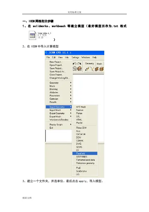
一、ICEM网格划分步骤
1、在solidworks、workbeach等建立模型(最好模型另存为.txt格式
)
2、在ICEM中导入计算模型
3、建立一个文件夹,并选单位。
最后点击apply,导入模型。
4、修复公差
默认参数,点击Apply。
5、生成BODY。
首先点击该按钮后,用鼠标左键点击模型,在不同的点上点击模型两次,然后点鼠标的中键。
最后单击Apply。
6、指定inlet、outlet、wall-inner、wall-outer 。
选面的时候一定要选完所对应的线。
7.file-GM-save GM as (保存到自己所见的文件夹里面)
8.mess mess尺寸大小,max element(根据模型大小设置)
9.生成mesh computer mesh。
10.用三菱柱网格细化边界特征,点击Prism 点击WALL 设置
Hight ratio 1.3 numlayer 5(表示增长率1.3 一共五层边界层) 视具体情况而定
11.编辑mesh --平滑mesh--UP TO MESH -0.4
12、检查mesh ,出现下面对话框后点击Yes,删掉多余的不相关的线。
12.file save project as
13.out --select solver--写出文件
最后生成如下文件。

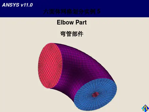
ICEM 实例——带圆环孔几何六面体网格划分在传热计算问题尤其是共轭传热问题中,经常出现固体中包含有管道的情景。
直管情况采用O型网格很容易对付,但是如果出现弯管,则难度大大增加。
本次的例子是一个单独的固体模型,没有添加流体域。
流体部分就是一段弯曲圆柱体圆形,很容易进行六面体网格划分。
好了,下面详细描述分块策略及网格划分步骤。
1、调入原始几何。
几何模型如图1所示。
图1 原始几何图2 C型块划分选取Face2、分块策略灵活运用O型剖分。
先进行C型剖分,然后进行O型剖分。
3、C型剖分创建3D Bounding Box原始块,选择图2所示的Face面,设定offset为1.6,进行O型剖分,划分后的块如图3所示。
图3 C型划分后的块图4 选取Face4、二次O型剖分选取图4所示的Face,设置offset为0.8,不需要特别进行block的选择。
进行O型剖分。
切分后的块如图5所示。
图5 二次O型剖分后的块图6 进行外O切分并删除多余块5、删除多余的块并进行关联在这一步可以进行外O网格切分,便于边界层生成,当然是在块删除之前。
在此例中需要进行面关联,即圆环面与块的Face相关联。
最终的块如图6所示。
6、设定网格尺寸,更新网格并预览网格制作外O剖分后的网格如图7所示。
未进行外O剖分如图8所示。
图7 最终网格图8 网格要不要添加外O型剖分只看个人爱好了。
添加了外O网格也只是方便边界层划分罢了。
当然不添加的话也可以控制,只是稍微麻烦一点点。
----ok,整个划分过程到此结束!。