ANSYS ICEM CFD中文教程
- 格式:pdf
- 大小:1.25 MB
- 文档页数:20
由yzmylh提供,版权所有……Ansys icemcfd 5.1 tutorial部分内容粗略翻译及理解,水平有限,如有问题或建议请联系liqingliang@,不胜感激。
感谢redhong等众多网友提供的资料和帮助,本人正在学习cfx,希望大家多多交流。
ANSYS ICEMCFD 5.1使用手册1. ANSYS ICEMCFD图形用户界面ANSYS ICEMCFD网格编辑器的标准化图形用户界面,提供了一个完善的划分和编辑数值计算网格的环境。
另外,自从ANSYS ICEM CFD 将相应的CAD模型(同样可以生成和编辑)与网格划分链接起来以后,网格编辑器允许用户在修改CAD模型后快速再生成新的网格。
对于为一个模型生成的网格可以被再次链接到一个新的CAD模型上,节约了重新划分网格的时间。
网格编辑器界面包括三个窗口:ANSYS ICEM CFD 主窗口模型的树状目录ANSYS ICEM CFD 信息窗口1.1:ANSYS ICEM CFD 主窗口除了图形显示区,在它的上部设置了一排按钮提供操作菜单,这些菜单包括:几何,网格,块,网格编辑,输出和post processing工具。
窗口的右上角有一串功能菜单,它们与以上这些菜单的选择无关。
文件:文件菜单提供许多与文件管理相关的功能,如:打开文件、保存文件、合并和输入几何模型、存档工程,这些功能方便了管理ANSYS ICEM CFD工程。
在这个菜单里有用的功能包括:新建工程、打开工程、保存工程、另存为、关闭工程、改变工作地址、几何菜单、网格属性、参数、结果、输入几何模型、输入网、输出几何模型和退出。
带有特殊标记的功能按钮包含有子菜单,可以通过点击看到。
编辑:菜单包括回退、前进、命令行、网格转换小面结构、小面结构转化为网格、结构化模型面。
视图:菜单包括合适窗口、放大、俯视、仰视、左视、右视、前视、后视、等角视、视图控制、保存视图、背景设置、镜像与复制、注释、加标记、清除标记、网格截面剖视。
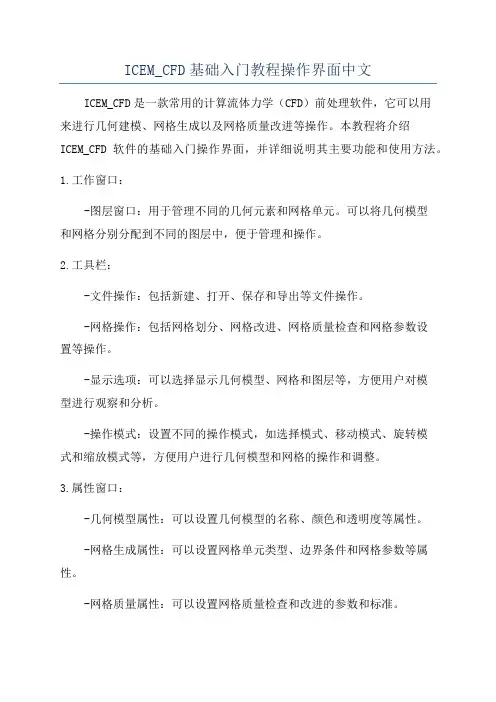
ICEM_CFD基础入门教程操作界面中文ICEM_CFD是一款常用的计算流体力学(CFD)前处理软件,它可以用来进行几何建模、网格生成以及网格质量改进等操作。
本教程将介绍ICEM_CFD软件的基础入门操作界面,并详细说明其主要功能和使用方法。
1.工作窗口:-图层窗口:用于管理不同的几何元素和网格单元。
可以将几何模型和网格分别分配到不同的图层中,便于管理和操作。
2.工具栏:-文件操作:包括新建、打开、保存和导出等文件操作。
-网格操作:包括网格划分、网格改进、网格质量检查和网格参数设置等操作。
-显示选项:可以选择显示几何模型、网格和图层等,方便用户对模型进行观察和分析。
-操作模式:设置不同的操作模式,如选择模式、移动模式、旋转模式和缩放模式等,方便用户进行几何模型和网格的操作和调整。
3.属性窗口:-几何模型属性:可以设置几何模型的名称、颜色和透明度等属性。
-网格生成属性:可以设置网格单元类型、边界条件和网格参数等属性。
-网格质量属性:可以设置网格质量检查和改进的参数和标准。
-显示属性:可以设置几何模型和网格的显示方式、颜色和透明度等属性。
4.建模流程:在ICEM_CFD中,进行建模和网格生成的一般流程如下:-导入CAD几何模型:可以通过导入现有的CAD几何模型文件,如STEP、IGES或者CATIA等文件格式,或者直接在ICEM_CFD中手动创建几何模型。
-网格划分:在几何模型的基础上进行网格划分,可以使用不同的网格划分算法和参数设置,生成合适的网格。
-网格改进:对生成的网格进行质量检查和改进,可以使用网格质量检查工具来查看和修复网格质量问题,并采用网格平滑和网格形变等操作来改进网格质量。
-边界条件设置:在网格上设置边界条件,包括流动边界条件、壁面边界条件和入出口边界条件等。
- 导出网格:将生成的网格导出为适用于CFD计算的文件格式,如ANSYS Fluent、OpenFOAM等格式。
通过上述步骤,可以完成几何建模和网格生成的基本操作和流程。
由yzmylh提供,版权所有……Ansys icemcfd 5.1 tutorial部分内容粗略翻译及理解,水平有限,如有问题或建议请联系liqingliang@,不胜感激。
感谢redhong等众多网友提供的资料和帮助,本人正在学习cfx,希望大家多多交流。
ANSYS ICEMCFD 5.1使用手册1. ANSYS ICEMCFD图形用户界面ANSYS ICEMCFD网格编辑器的标准化图形用户界面,提供了一个完善的划分和编辑数值计算网格的环境。
另外,自从ANSYS ICEM CFD 将相应的CAD模型(同样可以生成和编辑)与网格划分链接起来以后,网格编辑器允许用户在修改CAD模型后快速再生成新的网格。
对于为一个模型生成的网格可以被再次链接到一个新的CAD模型上,节约了重新划分网格的时间。
网格编辑器界面包括三个窗口:ANSYS ICEM CFD 主窗口模型的树状目录ANSYS ICEM CFD 信息窗口1.1:ANSYS ICEM CFD 主窗口除了图形显示区,在它的上部设置了一排按钮提供操作菜单,这些菜单包括:几何,网格,块,网格编辑,输出和post processing工具。
窗口的右上角有一串功能菜单,它们与以上这些菜单的选择无关。
文件:文件菜单提供许多与文件管理相关的功能,如:打开文件、保存文件、合并和输入几何模型、存档工程,这些功能方便了管理ANSYS ICEM CFD工程。
在这个菜单里有用的功能包括:新建工程、打开工程、保存工程、另存为、关闭工程、改变工作地址、几何菜单、网格属性、参数、结果、输入几何模型、输入网、输出几何模型和退出。
带有特殊标记的功能按钮包含有子菜单,可以通过点击看到。
编辑:菜单包括回退、前进、命令行、网格转换小面结构、小面结构转化为网格、结构化模型面。
视图:菜单包括合适窗口、放大、俯视、仰视、左视、右视、前视、后视、等角视、视图控制、保存视图、背景设置、镜像与复制、注释、加标记、清除标记、网格截面剖视。
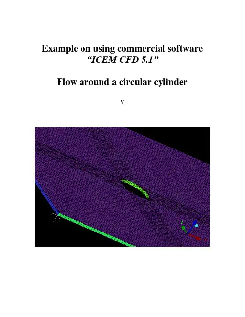
Example on using commercial software“ICEM CFD 5.1”Flow around a circular cylinderYTwo Dimensional problemsFlow around a circular cylinderProblem DescriptionAir flows across a cylinder with the uniform velocity in the wind tunnel. The length of the wind tunnel (fluid domain) has 25m long and 10 m height. The diameter of cylinder is 1m .Assumption and Boundary Conditions: 1. 2 dimensional problems 2. Steady state condition 3. The uniform flow velocity 4. No Heat transfer5. Neglect the gravitational force6. Constant air densityPre-processing stageIn this stage, we implement the “ICEM CFD” to perform the pre-processing work. The basic steps as follow:1. Establish geometry model2. Block the parts3. Generation the O grid4. Mesh the model and check quality of mesh5. Extrude the mesh6. R eset the BC’s (boundary conditions)7. Output toCreating Geometry1. Open ICEM CFDDouble Click the “ICEM CFD” Icon , afterwards, you can see the interface of the ICEM CFD.InletOutlet5DCylinderWall (SideB) Fluid domain5D20DWall (SideA)Open File>New Project…:2. Creating Geometry:A.PointsClick button “C reate Point ” and then click button “Explicit Coordinates ”Set the points in Cartesian coordinate system(X, Y, Z) with( X=0, Y=0, Z=0 ) respectively.Click “Apply” button and see the screen: a point is createdA tree widget can be seen at left of the screen (A) and (B)A BThe same method creates other points:X=-5; Y=5, -5X=20; Y=5, -5B.Draw line (curve)First of all see the tree widget, open Model>Geometry>Points by right buttonSelect Show Point Names and you can see the name ofeach point like the figure showed.Now you can create curvesClick button “Create/Modify Curve”Click button “Create Curve”Note: the left corner of the black screen: Select locationswith left button, middle=done, right=cancelSelect points by using left button of the mouse.Change the name of the Part with “INLET”:A BSelect and with left button (A),And draw a line with middle button “done”(B) and the INLET part is created in the tree widget.The same steps draw the curves named “OUTLET, SIDEA, SIDEB” with the 7and 8, and , POINTS.05 and respectively.We will see the line and the tree widgetDraw the cylinderClick button“Circle or arc from Center point and 2 points on plane ”.Set the Part with name “CYLINDER”Click button and select points “POINTS.00,POINTS.01, POINTS.03” with left button respectively(A).A BDraw the cylinder by middle button (B).See tree widget:Close Points name Use button to fit the window.Set the body and material.Click button “Create Body”Choose button “Mater ial Point”and select“Selected surfaces” in the “By Topology” menu.Change the name of the part with “FLUID”; open theShow Point Name of the tree widget and use selectand .The same way change the part name with “CYLINDER”and select and .Close Show Point Name and open the tree widget:Open the bodies and you can seeAt last, open the File>Geometry>Save Geometry As…Give it the name with “cylinder_2d”. Click “save”.Now we begin to block the model.Click button “Create Block”See the first one , choose the part with “FLUID”,from the pull down menu select “FLUID”And set the Initialize Blocks type with “2D Planar”Click “Apply” button.A BWe will see that the colors of figure are changed. From (A) to (B)See the tree widget: Model>BlockingThen create some assistant points with button “CreatePoint”{Y=0X=-0.45,-0.4,-0.35,-0.3,-0.25,-0.2,-0.15,-0.1,-0.5, 0.5,0.1, }{X=0}Now begin to block the regionClick button “Split Block”Then select button “Split Block”See the split method, select “Prescribed point”Use the put down menu to select the Prescribed point,Use the button firstly select the Edge “INLET” andsecondly select the Point “POINTS.03”.We will see the block line in the vertical direction of theINLET.Zoom the fiure.The same way we draw other block lines.From the to POINTS.04”See the tree widgetSelect the “Blocking” and select “Index Control”Model>Blocking: Index Control (using right button of the mouse) We can see at the right corner of the screenBy using button and we set I min=2 and see the figure The same way we set I max =3 , J min=2 , J max=3And the screen shown thatThe same way block again from to POINTS.44”:(A)(B)(C)A B CAfter block.See the tree widget: Model>Parts>VORFN :using the right button select “Add to Part”. Click button “Blocking Material”, Add Blocks to PartUsing select blocking regions and we can seeZoom the block regions (A).Select the blocks in the cylinder or attached the cylinder (B)(C).Using the middle button to set it OK , and you can see blow (D).Click button “Associate”ABD CSelect the associate edge to curve “Associate Edge toCurve”buttonUsing the choose the edge and curveChoosing edge:Select curves:Middle button:CBASet O gridClick button “Split Block”Click “Ogird Block”buttonSelect theSee the tree widget: Open Model>Parts>VORFNOpen the VORFN (A)AUsing button to selectin or attached the cylinder (B)(C)(D).B CD EUsing middle button to click “Apply”(E)Close “VORFN” from the tree widget (F)F GClick the “Reset”(G)Mesh the edgesClick button “Set Curve Mesh Size”Using button to select Curve(s):Choose Method with “Element count”Set the Number with 100 and click Apply.See the tree: close the Model>Geometry>points, and theModel>Blocking>edgesUsing right button to select Model>Geometry>Curves:Curve Node Spacing (by using right button)The same way set the “INLET” and “OUTLET” withnumber 100, the “SIDEA” and “SIDEB” with number 250.Click button “Pre-Mesh Params”Choose Blocking >Pre-Mesh ParamsClick button “Update Sizes” and keep default,Then click ApplySee tree open Model>Blocking>Pre_Mesh: Project faces(by using right button)And we will see a menuClick Yes.Now we will see the mesh of the model.Zoom it see the local partClose Geomery>Points and curves, and Blocking>Edges.Then open File>Mesh>Load from BlockingOpen File>Mesh>Save Mesh As…: and set the name with “cylinder_2d”Open File>Blocking>Save Blocking As…: Save block with the name “cylinder_2d”Check the quality of the meshClick button “Display Mesh Quality”Click ApplyWe can see no negatives mesh.Extrude meshClick button “Extrude Mesh”Use to select Elements:Method 1Click button “Select items in a part” and a menu appears:Click “All” and “Accept”Method 2A BPut the left button and drag it to select all the regions (A)(C). Click middle button to accept (B)Give the New volume part name “FLUID2D”, new side part name “SIDE”, new top par name “TOP”And set the Spacing type>spacing with ”, then ApplyCSo the mesh change a height in the Z direction (D)DBox ZoomE FClick button “Shaded Full Display”(E)(F) Check the quality of the extrude meshSee the tree widget:Close top “TOP” (B) Close “FLUID” (C)A BSet the new boundary conditionsSee the tree widget:Model>Parts: Create Part (by using the right button)Click “Create Part by Selection ” button From the pull down menu of the Part: select the “CYLINDER ” Using and left button drag the regionUsing middle button accepts it, so a new CYLINDER boundary condition has been set (C).CBACThe same way set the INLET, OUTLET, SIDEA and SIDEB boundary conditions. INLETThe Whole Boundary Conditions See the tree widget: CA BA Open Model>Parts>FLUID(B)B Open Model>Parts>TOP(C)CSix kinds of patterns Click File>Mesh>Save Mesh As… And save the new mesh with name “cylinder_2d_extrude”.Output the mesh file to CFXClick button “Select solver ” and choose “CFX-5” Click “Okay ”C B FE D AClick button “Write input”Keep default and click “Done”Then the Domain selection appearsKeep the Selected domains with “cylinder_2d_extrude.uns” and click “Done”.Now we will see the created files in working directions:From these files, we must note that only the file named “cfx5” can be inputted in to .1 The mesh is finished.Other examples:。
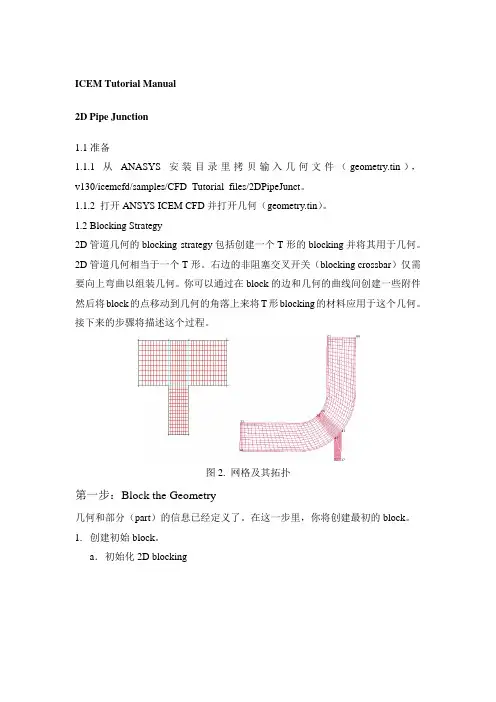
ICEM Tutorial Manual2D Pipe Junction1.1准备1.1.1 从ANASYS安装目录里拷贝输入几何文件(geometry.tin),v130/icemcfd/samples/CFD_Tutorial_files/2DPipeJunct。
1.1.2 打开ANSYS ICEM CFD并打开几何(geometry.tin)。
1.2 Blocking Strategy2D管道几何的blocking strategy包括创建一个T形的blocking并将其用于几何。
2D管道几何相当于一个T形。
右边的非阻塞交叉开关(blocking crossbar)仅需要向上弯曲以组装几何。
你可以通过在block的边和几何的曲线间创建一些附件然后将block的点移动到几何的角落上来将T形blocking的材料应用于这个几何。
接下来的步骤将描述这个过程。
图2. 网格及其拓扑第一步:Block the Geometry几何和部分(part)的信息已经定义了。
在这一步里,你将创建最初的block。
1.创建初始block。
a.初始化2D blockingi.在Part区域中输入FLUID。
ii.在Type下拉菜单中选择2D Plannar。
iii.点击Apply。
b.在Blocking下激活Vertices。
c.在Vertices下选择Numbers。
将blocking下面的Vertices前面的方框勾选,右击,在弹出菜单中选择Numbers即可。
图2给出了包裹几何的初始block。
你将使用这个初始block来创建这个模型的拓扑。
图3. 初始block这些曲线现在被分别上色,并不是由不同部分。
这样可以使你区别不同的曲线实体,这对于某些blocking操作时非常必要的。
你可以通过选择/不选Show Composite激活或者不激活上色命令。
2.将初始block分割为次级block。
本案中,你将使用两个垂直分割和一个水平分割将初始block分割。

ICEMCFD中文入门教材MSC.Sinda.v2008.R1-ISO 1CD(热流分析)MSC.Sofy.v2007.R1-ISO 1CD(通用有限元前后处理器)MSC.Superforge.v2005.MP1-ISO 1CD(功能强大的3D锻造制程模拟分析工具,能有效地用来观察比较钢模与锻造程序制程的不同,对各种制程特性的影响,包括:材料流动、最后工件的形状与机械性质、多余材料区(material flash region)等,以期能用最省的材料、最短的时程,得到机械性质最符合预期的锻造产品,适用于冷锻和热锻分析)MSC.SuperForm.v2005-ISO 1CD(体积成型工艺过程仿真专用软件)MSC.FEA.AFEA.v2006.R1-ISO 2CD(有限元分析)MSC.Easy5.v2008.R1-ISO 1CD(一整套工程师们模拟系统的概念设计和验证工具,用于宇航、汽车和其他工业领域。
分析工具如非线性仿真、稳态分析、线性分析、控制系统设计、数据分析和测绘等均可用于测试系统级的部件如:阀门、激振器、热交换器、齿轮、离合器、发动机、气体力学、飞行动力学和其他系统)MSC.Easy5.v2008.R1.Unix-ISO 1CDMSC.MARC.v2005.R3-ISO 1CDMSC.Marc.2005.R2.Final -ISO 2CDMSC Marc 2005 Amd for Linux 1CDMSC Marc With Mentat v2003-ISO 1CDMSC.Marc v2005 培训教程MSC.MARC 资料(marc中文基本手册+MARC中文资料)MSC MARC 有限元实例分析教程MSC.RobustDesign.v2004.R3.5-ISO 1CD(Software仿真产品中的概率设计产品,它能够高效地处理多变量)MSC Working model 2D 2004 v7.0 1CD(一个概念设计工具,可以对机械系统进行仿真以代替模糊、耗时而不准确的抽象计算)MSC 系列教程MSC Patran 、Nastran & Marc 原厂培训 1CD专业提供CAD/CAM/CAE/CFD/GIS/EDA/AI/FEM软件QQ:627655105联系邮件:**********************************@MSN:**********************HKS 产品:Abaqus v6.8.1 Win32 & Win64-ISO 1DVD(最新版,不需要安装Exceed)Abaqus.v6.8.1.Linux32-ISO 1DVDAbaqus.v6.8.1.Linux.64Bit-ISO 1DVDAbaqus v6.6中文培训资料Abaqus v6.5 英文用户手册Abaqus有限元软件6.4版入门指南(中文版)Abaqus/Standard 有限元简体中文入门电子书Abaqus Explicit 有限元简体中文入门电子书Abaqus/Exercise Workshop Cougar(学习资料)Abaqus/Umat Micromechanical Models (英文版资料)Abaqus/Lectures Liflutter (ABAQUS原厂培训资料)Abaqus 使用手册(中文)ABAQUS 使用解答(中文)CRANES产品:Cranes NISA v15.1-ISO 3CD(综合FEA有限元分析)CAD Translators for Cranes NISA v15.1 1CD(CAD数据转换工具)ESAComp产品:ESAComp v3.0 for WinXP 1CD(复合材料结构设计的专用软件)Lammps 2001 源代码 1CDNIST-Refprop v7.0 1CD(计算物性的软件)Wien2k 1CD二元合金相图 Binary Alloy Phase Diagrams-ISO 1CD(软件版)材料力学计算软件3.4Flow Science产品:Flow 3D 9.3 Win32-ISO 1CD(完全解密,压铸模拟软件)Flow 3D 9.3.1 Update Only 1CDFlow 3D 9.3 Win64-ISO 1CDFlow 3D 原版教程Flow 3D 英文资料Flow 3D 初级入门教程FlowVision v2.30 1CDDDS产品:FEMtools.v3.3.Win32 1CD(振动灵敏度分析软件)FEMtools.v3.3.Win64 1CDNetwork Analysis Inc产品:Sinda/G.Application.Suite.v2.6 Working-ISO 1CD(有限差分析器软件)MAGNA产品:FemFat v4.6B 1CD(用于对部件进行疲劳测试的软件。
ANSYS.ICEM-CFD中文教程ICEM CFD 工程Tutorials目录中每个工程是一个次级子目录。
每个工程的目录下有下列子目录:import, parts, domains, mesh, 和transfer。
他们分别代表:• import/: 要导入到ICEMCFD中的集合模型交换文件,比如igs,STL等;• parts/: CAD模型• domains/: 非结构六面体网格文件(hex.unstruct), 结构六面体网格分区文件(domain.n), 非结构四面体网格文件(cut_domain.1)• mesh/: 边界条件文件(family_boco, boco),结构网格的拓扑定义文件(family_topo, topo_mulcad_out), 和Tetin几何文件(tetin1).• transfer/: 求解器输入文件(star.elem), 用于Mom3d.的分析数据mesh目录中Tetin文件代表将要划分网格的几何体。
包含B-spline曲面定义和曲线信息,以及分组定义Replay 文件是六面体网格划分的分块的脚本鼠标和键盘操作第二章ICEM CFD Mesh Editor界面The Mesh Editor, 创建修改网格的集成环境,包含三个窗口• The ICEM CFD 主窗口• 显示窗口• The ICEM CFD 消息窗口主窗口主窗口中除了图形显示区域,外,还有6个radio按钮:File, Geometry, Meshing, Edit Mesh and Output.The File MenuThe File menu 包含• Open, Save, Save as, Close, Quit, Project dir, Tetin file,Domain file, B.C file, Import geo, Export geo, Options, Utilities,Scripting, Annotations, Import mesh, DDN part.The Geometry MenuThe Geometry menu 模型修补和编辑,边界条件的设置,调用ICEM CFD DDN。
它包含• DDN tools, Bound conds, Repair, Utilities, Global setup.模型编辑模式,由一排彩色radiobuttons控制• Surface, Curve, Point, Material, Density, Loop.它们又分别具有次级菜单• Create, Delete, Modify, Mesh params, Change family,Copy/move.The Meshing MenuThe meshing menu 包含ICEM CFD各种网格划分模块。
只有用户拥有楼阁模块的license,他才可以使用这个模块。
目前ICEMCFD提供下列模块:• Hexa, Tetra, Global, Prism, Quad, AutoHexa, Mulcad/Padamm,P-Cube按不同的按钮会调用不同的模块。
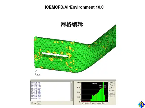
The Edit Mesh MenuThe Edit Mesh menu包含必要的网格编辑功能, 粗化、平滑合并等。
具体的操作有:• Copy/move, Smooth, Refine, Coarsen, Merge, Extrude,Diagnostics, Uncouple, Bandwidth, Change type, Changefamily, Utilities, Edit nodes, Edit elements, Edit edges, EditBlocks, Edit subfaces, RepairThe Output MenuThe Output menu针对不同求解器进行边界条件的设置。
此外用户可以调用Mom3d 和Visual3 进行网格自适应和可视化。
可使用的功能有:• Select solver, Bound conds, Solver params, Solver input,Run solver, Visual3, Mom3d, RAMM-ICENote: The ICEM CFD 后处理模块Visual3, 网格优化模块Mom3d, 以及与RAMM-ICE的内燃机网格接口必须有另外的licenseThe Utilities Cluster这些功能都位于主窗口的右上角:• Help: connects the user to the ICEM CFD on-line help• Orient: 控制显示坐标• View: 定制显示属性• Undo: 操作反悔• Redo: 撤销反悔• Print: 打印• Shell: 调用一个X-Term命令窗口显示窗口The display window, 处于屏幕右边, 允许控制按照family, geometric entity, elementtype and user-defined subsets来显示.Important: Since some functions are performed only on the entities shown, the Display window is a very important feature to use when isolating the particular entities to be modified.FamiliesColor-coded and customizable, display by family, as defined in the mesher interface, is available in this window.GeometryWhen this button is toggled on, the user has control over thedisplay of geometric entities. The Opts button beside for eachentity type allows control over the display characteristics.Note: Based on the domain file chosen, this toggle button willeither be labeled “unstructured” or “structured,” or be absentaltogether if no domain file is specified.• Structured or Unstructured: Aside from display of the meshbased on element type, for even greater power, ICEM CFDallows the user to create custom subsets; the careful display ofwhich allows a great deal of control in the mesh operations.• Display Subset: This toggle button allows you to define subsetof your model based on a set of numerous attributes, includingelement type, screen selection, coordinate position, etc.第三章ICEM CFD Tetra四面体网格划分器自动对CAD模型或者STL模型生成四面体网格,无需先生成表面网格这是Tetra生成的棱拄和四面体混合网格,包含55万四面体网格和12层33万棱拄网格介绍Tetra采用8叉树算法来对体积进行四面体填充并生成表面网格。
用户必须事先规定一些关键的点和曲线。
Tetra具有强大的网格平滑算法,以及局部适应性加密和粗化算法。
对于复杂模型,ICEM CFD Tetra具有如下优点:• 基于8叉树算法的网格生成• 快速模型set-up• 网格与表面拓扑独立• 无需表面的三角形划分• 可以直接从CAD模型和STL数据进行网格生成• 对CAD surfaces and/or STL Representation定义网格尺寸• 控制体积内部的网格尺寸• 四面体的节点和曲线与事先的规定匹配• 采用Natural size 单独的决定几何特征上的四面体网格尺寸• 体积网格和表面网格的平滑、节点合并和边交换• 四面体网格能够合并到混合网格中,并实施平滑操作• 单独区域的粗化• Enforcement of mesh periodicity, both rotational and translational• 表面网格编辑和诊断工具• 局部细化和粗化• 为多种材料提供一个统一的网格• 快速算法: 1500 cells/secondICEM CFD Tetra的输入ICEM CFD Tetra的输入方法有:• Sets of B-Spline curves and trimmed B-Spline surfaces withprescribed pointsICEM CFD Tetra中的智能几何ICEM CFD的CAD接口,保留有CAD几何模型的参数化描述,网格可以在修改过的几何模型上重新生成。
在CAD中选中被导入的模型带有附加的信息,它们与主几何模型一起存储,几何模型的参数改变后,用户要重新生成网格只需简单的File > Save,就可以立即进行非结构四面体网格重新计算。
八叉树算法Tetra网格生成是基于如下的空间划分算法:这种算法需要的区域保证必要的网格密度,但是为了快速计算尽量采用大的单元。
1.在几何模型的曲线和表面上规定网格尺寸2.构造一个初始单元来包围整个几何模型3.单元被不断细分来达到最大网格尺寸(每个维的尺寸按照1/2分割,对于三维就是1/8)4.均一化网格来消除悬挂网格现象5.构造出最初的最大尺寸单元网格来包围整个模型6.节点调整以匹配几何模型形状7.剔除材料外的单元8.进一步细分单元以满足规定的网格尺寸要求9.通过节点的合并、移动、交换和删除进行网格平滑Family设置, Material Points, 预先规定Points在ICEMCFD中可以对几何模型中的各种几何元素进行分组,形成不通的families。