外文翻译---基于LabVIEW的电流互感器校验仪
- 格式:docx
- 大小:558.61 KB
- 文档页数:14
LabVIEWLabVIEW is a highly productive graphical programming language for building data acquisition an instrumentation systems.With LabVIEW, you quickly create user interfaces that give you interactive control of your software system. To specify your system functionality,you simply assemble block diagrams - a natural design notation for scientists and engineers. Tis tight integration with measurement hardware facilitates rapid development of data acquisition ,analysis,and presentation bVIEW contains powerful built -in measurement analysis and a graphical compiler for optimum performance. LabVIEW is available for Windows 2000/NT/Me/9x, Mac OS, Linux, Sun Solaris, and HP-UX, and comes in three different development system options.Faster DevelopmentLabVIEW accelerates development over traditional programming by 4 to 10 times! With the modularity and hierarchical structure of LabVIEW, you can prototype ,design, and modify systems in a short amount of time. You can also reuse LabVIEW code easily and quickly in other applications.Better InvestmentUsing a Lab VIEW system, each user has access to a complete instrumentation laboratory at less than the cost of a single commercial instrument. In addition, user configurable LabVIEW systems are flexible enough to adapt to technology changes, resulting in a better bong-term investment.Optimal PerformanceAll LabVIEW applications execute at compiled speed for optimal performance. With the LabVIEW Professional Development System or Application Builder, you can build stand-alone executables or DLLs for secure distribution of your code. You can even create shared libraries or DLLs to call LabVIEW code from other programming languages.Open Development EnvironmentWith the open development environment of LabVIEW, you can connect to other applications through ActiveX, the Web, DLLs, shared libraries, SQL(for databases), DataSocket, TCP/IP,and numerous other e LabVIEW to quickly create networked measurement and automation systems that integrate the latest technologies in Web publishing and remote data sharing. LabVIEW also has driver libraries available for plug-in data acquisition, signal conditioning , GPIB,VXI,PXI, computer-based instruments,serial protocols, image acquisition, and motion control. In addition to the LabVIEW development systems, National Instruments offers a variety of add-on modules and tool sets that extend the functionality of LabVIEW .This enables you to quickly build customizable, robust measurement and automation systems.LabVIEW Datalogging and Supervisory Control ModuleFor high channel count and distributed applications, the LabVIEW Datelogging and Supervisory Control Module provides a complete solution. This module delivers I/O management, event logging and alarm management, distributed logging, historical and real-time trending, built-in security, configurable networking features, OPC device connectivity, and over 3,300 built-in graphics.LabVIEW Real-TimeFor applications that require real-time performance, National Instruments offers LabVIEWReal-Time. LabVIEW Real-Time downloads standard LabVIEW code to a dedicated hardware target running a real-time operating system independent from Windows.LabVIEW Vision Development ModuleThe LabVIEW Vision Development Module is for scientists, automation engineers,and technicians who are developing LabVIEW machine vision and scientific imaging applications. The LabVIEW Vision Development Module includes IMAQ Vision, a library of vision functions, and IMAQ Vision Builder, an interactive environment for vision applications. Unlike any other vision products, IMAQ Vision Builder and IMAQ Vision work together to simplify vision software development so that you can apply vision to your measurement and automation applications.Countless ApplicationsLabVIEW applications are implemented in many industries worldwide including automotive, telecommunications, aerospace, semiconductor, electronic design and production, process control, biomedical, and many others, Applications cover all phases of product development from research to design to production and to service. By leveraging LabVIEW throughout your organization you can save time and money by sharing information and software.Test and MeasurementLabVIEW has become an industry-standard development tool for test and measurement applications. With Test Stand, LabVIEW-based test programs, and the industry's largest instrument driver library, you have a single, consistent development and execution environment for your entire system.Process Control and Factory AutomationLabVIEW is used in numerous process control and factory automation applications.Many scientists and engineers look to LabVIEW for the high speed, high channel count measurement and control that graphical programming offers.For large, complex industrial automation and control applications, the LabVIEW Data logging and Supervisory Control Module provides the same graphical programming as LabVIEW, but is designed specifically for monitoring large numbers of I/O points, communicating with industrial controllers and networks, and providing PC-based control.Machine Monitoring and ControlLabVIEW is ideal for machine monitoring and predictive maintenance applications that need deterministic control, vibration analysis, vision and image processing, and motion control. With the LabVIEW platform of products including LabVIEW Real-Time for real-time deterministic control and the LabVIEW Data logging and Supervisory Control Module, scientists and engineers can create powerful machine monitoring and control applications quickly and accurately.Research and AnalysisThe integrated LabVIEW measurement analysis library provides everything you need in an analysis package. Scientists and researchers have used LabVIEW to analyse and compute real results for biomedical, aerospace, and energy research applications, and in numerous other industries. The available signal generation and processing, digital filtering, windowing, curve-fitting, For specialized analysis, such as joint time-frequency analysis, wavelet,and model-based spectral analysis, LabVIEW offers the specially designed Signal Processing Toolset.The Sound and Vibration Toolset offers octave analysis, averaged and nonaveraged frequency analysis, transient analysis, weighted filtering, and sound-level measurement, and more.Draw Your Own SolutionWith LabVIEW, you build graphical programs called virtual instruments (VIs) instead of writing text-based programs. You quickly create front panel user interfaces that give you the interactive control of your system. To add functionality to the user interface, you intuitively assemble block diagrams- a natural design notation for engineers and scientists.Create the Front PanelOn the front panel of your VI, you place the controls and data displays for your system by selecting ob jects from the Controls palette, such as numeric displays, meters, gauges, thermometers, LEDs, charts,and graphs.When you complete and run your VI,you use the front panel to control your system whether you move a slide, zoom in on a graph, or enter a value with the keyboard.Construct the Graphical Block DiagramTo program the VI, you construct the block diagram without worrying about the syntactical details of text-based programming languages. You do this by selecting objects (icons) from the Functions palette and connecting them together with wires to transfer data among block diagram objects. These objects include simple arithmetic functions, advanced acquisition and analysis routines, network and file I/O operations, and more.Dataflow ProgrammingLabVIEW uses a patented dataflow programming model that frees you from the linear architecture of text-based programming languages. Because the execution order in LabVIEW is determined by the flow of data between nodes,and not by sequential lines of text,you can create block diagrams that execute multiple operations in parallel. Consequently, LabVIEW is a multitasking system capable of running multiple execution threads and multiple VIs in parallel.Modularity and HierarchyLabVIEW VIs are modular in design, so any VI can run by itself or as part of another VI. You can even create icons for your own VIs, so you can design a hierarchy of VIs that serve as application building blocks. You can modify, interchange, and combine them with other VIs to meet your changing application needs.Graphical CompilerIn many applications, execution speed is critical. LabVIEW is the only graphical programming system with a compiler that generates optimized code with execution speeds comparable to compiled C programs. You can even use the LabVIEW profiler to analyse and optimize time-critical operations. Consequently, you increase your productivity with graphical programming without sacrificing execution speed.Measurements and MathematicsLabVIEW includes a variety of other measurement analysis tools. Examples include curve fitting, signal generation, peak detection, and probability and statistics. Measurement analysis functions can determine signal characteristics such as DC/RMS levels, total harmonic distortion (THD),impulse response, frequency response, and cross-power spectrum. LabVIEW users can also deploy numerical tools for solving differential equations, optimization, root finding, and other mathematical problems.In addition, you can extend these built-in capabilities by entering MATLAB or HIQ scripts directly in your LabVIEW programs. For charting and graphing, you can rely on the built-in LabVIEW 2D and 3D visualization tools. 2D tools include features such as autoscaling X and Y ranges, reconfigurable attributes (point/line styles, colors, and more)andcursors, Microsoft Windows users can employ OpenGL-based 3D graphs and then dynamically rotate, zoom, and pan these graphs with the mouse.Development SystemThe LabVIEW Professional Development System facilitates the development of high-end, sophisticated instrumentation systems for developers working in teams, users developing large suites of VIs, or programmers needing to adhere to stringent quality standards.Built on the Full Development System, the Professional Development System also includes the LabVIEW Application Builder for building stand-alone executables and shared libraries (DLLs)and creating distribution kits. In addition, the development system furnishes source code control tools and offers utilities for quantitatively measuring the complexity of your applications. With graphical differencing, you can quickly identify both cosmetic and functional differences between two LabVIEW applications.We include programming standards and style guides that provide direction for consistent LabVIEW programming methodology. The system also contains quality standards documents that discuss the steps LabVIEW users must follow to meet internal regulations or FDA approval. The Professional Development System operates on Windows 2000/NT/Me/9x,Mac OS, HP-UX, and Linux.LabVIEW Full Development SystemThe LabVIEW Full Development System equips you with all of the tools you need to develop instrumentation systems. It includes GPIB, VISA, VXI, RS-232, DAQ, and instrument driver libraries for data acquisition and instrument control. The measurement analysis add DC/RMS measurements, single tone analysis, harmonic distortion analysis, SINAD analysis, limit testing, signal generation capabilities, signal processing, digital filtering, windowing, curve fitting, statistics, and a myriad of linear algebra and mathematical functions. The development system also provides functions for direct access to DLLs, ActiveX, and other external code. Other features of the system include Web publishing tools, advanced report generation tools, the ability to call MATLAB and HiQ scripts, 3D surface, line, and contour graphs, and custom graphics and animation. The Full Development System operates on Windows 2000/NT/Me/9x, Mac OS, HP-UX, and Linux.LabVIEW Base PackageUse the LabVIEW Base Package, the minimum LabVIEW configuration, for developing data acquisition and analysis, instrument control, and basic data presentation. The Base Package operates on Windows 2000/NT/Me/9x.Debug License for LabVIEWIf you deploy LabVIEW applications, including LabVIEW tests for use with Test Stand, the debug license allows you to install the LabVIEW development system on the target machines so you can step into your test code for complete test debugging. This license is not intended for program development.虚拟仪器(LabVIEW)虚拟仪器是一种高效用于构建数据采集与监测系统图形化编程语言。
附录A LabVIEW Based Instrument Current Transformer CalibratorXin Ai Hal Bao Y.H. Song1) North China Electric Power University, Beijing, China 1072062) Brunel University. UKABSTRACTThe Virtual Instrument (VI) mainly refers to build all kinds of instruments by software such as LabVIEW, which likes a real instrument build in a computer. Its' main characteristics are flexibility, multi-functions, multiple uses for one PC computer, giving high performance, and is less costly. In this paper, the VI technology is applied to the test and measurement of instrument current transformer (TA). By using the LabVIEW, the TA accuracy calibrator was developed. This virtual T.4 calibrator can automatically measure the accuracy of T.4 and can indicate the ratio error and phase error curves. The tests and calibration for the TA show that the virtual TA calibrator can be used in place of the traditional calibrator and is much better than the traditional one.Keywords:Instrument current transformer (TA), TA calibrator, Virtual Instruments, LabVIEW.I. INTRODUCTIONSince 1992 the VXIbus Rev.1.4 standard was established by the United States and LabVIEW was presented by the National Instruments co.(Nl), the Virtual Instrument (VI) have lain the foundation for its commercial use. The main characteristic of Virtual Instrument is that it makes instruments by software. Most of the traditional instrument can be developed by VI. The VI is a real instrument made by the personal computer.The Instrument current transformer (TA) is widely used in all kinds of current measurement and it has the functions of protection, isolation and extending the measuring range. With the rapid development of computer measurement and controltechnology, and with the sequent emergence of current transformer and transducer, there is an increasing number of current transformers with high accuracy and low secondary current. The standard TA secondary current is usually1A or 5A: some non-standard TA secondary current may be 0 1A or lower. Although we have the technique to make this kind of calibrator by means of hardware such as single chip computer and electronic circuit, DSP and so on, it will cost too much money for these no-standard calibrator and will take too much time and the calibrator made by these hardware mill not be satisfactory in both function and practicality for designing all kinds of new TA.The calibrator that adopts VI technology not only can meet the requirements of the traditional one but also can satisfy customers with such advantages as multi-functions, convenience, and high ratio between performance and cost. The experiment results indicate that the virtual calibrator can provide excellent condition for TA measurement and design. The VI technology and personal computer must be widely used in the area of calibration on instrument transformer.Ⅱ. THE WORKING PRINCIPLE OF TA CALIBRATOR The error of TA includes ratio error and phase error. The measuring of the error of TA or the calibration of the accuracy of TA usually applies differential measuring method. The method needs a standard TA except the measured TA and a TA calibrator. There is the same turn ratio between the standard and measured T4 and the standard TA's accuracy should be 2 levels higher than the measured one. The calibrator function lies in forming comparison circuits, measuring, and showing the error at all range. The comparison circuit, also referred to the difference measuring principle circuit, is showed in Fig. 1. By measuring the voltage on I, and Rd, calculate the corresponding current. Then the calibrator can indicate the error.When a TA has the same turn ratio between the primary and secondary winding, the self-comparison circuit could be used and is shown in Fig.2. In the figures, TA0 and TAX are standard and TA being measured respectively. Np and Ns are primary and secondary winding turns. ip and io, id, i, are primary current secondary standard current, secondary error current, secondary current of TA being measured respectively. Ro and R,R, are secondary winding's resistance of standard TA, error current detecting resistance, burden resistance of TA being measured respectively. To and K, Tb. T, are voltage sampling points which can calculate the current In this paper, only voltage between K and T, voltage between Tb and T, are being measured and they represent the voltage on R, and R, respectively.In general, the TA calibrator's principle of the sample resistance should be: 1) it can not affect the accuracy of the comparison circuit. In the ideal condition R, and Rd should be 0, but it can not be sampled. So there must be sample resistance, in this paper, R, as shown in Fig, is used;1)the magnitude of the sample resistance should make the sampled standard current and error current in pro rata and should not have too much difference. The sampled resistance is set by experiment: R, is the secondary standard current sampling resistance and can be 0.1-0.50, R, is the error current sampling resistance and can be, R, is the burden resistance and it depends on the TA being measured. E$ sampling the voltage uo and U, on R, and R, respectively, the ratio error and phase error are showed on the LED through some process and calculations.According to the TA error's phase diagram, when io is maximum, the value of id is the ratio error; when io changes from negative to positive and equals to 0, the value of id is the phase error. For the same principle, the relationship is equal to the voltage signal U, and ud. showed in Fig.3. a and b is represent the ratio error and phase error separately. the TA's real ratio error C and phase error 6 can be found out through proper calculation,Where U, is the amplitude of uo The T.4 calibrator doesn't need very high accuracy. 1% to 3% error for the calibrator is enough. Because of the difference measuring principle, the error is the read error of calibrator, that is, the TA's error's error being measured. But the calibrator needs to have a suitable enlargement factor. The calibrator maximum enlargement factor through all channels should be 1000 times.III. THE PRINCIPLE OF VIRTUAL CA LIBRATORThe Virtual Instrument consists of three parts: the external comparison circuit (showed in Fig.1 or Fig.2), data acquisition card (PCI-6023) installed in the PC and the VI program by LabVIEW Then, after the two channels' signal U, and ud come into the PC through the ADC, the rest of the work is done by the software. In this paper we use voltage U, on R, substitute for U, approximatively. The virtual calibrator's work flow chart is shown as follow:1) Set the essential initial values of the virtual calibrator;2) Press the start button to start to work, adjusting the voltage regulator andchanging the primary current, let the ratio between primary current and the rated current change from10% to 120%;3) The VI program will group the voltage signal U, and ud , then use the digitalfilter to eliminate the harmonic:4) Calculate the root-mean-square (RMS) value of tlx and 14, find out the amplitude of 21;5) Calculate the RMS valve of io (substitute for f, ), i, and the ratio between io and it's rated current and show the results.6) Find out the a and b showed in Fig. 3, calculate the ratio error and phase error and show the results.7) Set the L times loop, record and show the errors acquired by every time,8) Show and print all the results of calibration.9)Stop.The front panel of the virtual calibrator has the Controls, indictor and Switch.The function of Controls is to set the initial value before it works, The function of the Indictor is to show at1 kinds of needed values, including digital, curve and diagram etc.. 'The switch decides the start and stop of the virtual calibrator.Of course, to change the measuring range, the operator needs to adjust the voltage regulator and change the primary current. This operation is necessary like that of the traditional calibration, but the recording for the error in any range is done by the virtual calibration. This confirms the accuracy of recording and relieves the operator's work. The use of virtual calibrator is most interesting.The controls of virtual calibrator include:1) Setting the two sampling (analogue input) channels;2) Setting the magnitude of sampling resistance in the comparison circuit;3) Setting the secondary rated current of measured TA;4) Setting the number of sampling of error curve;The Indictor of virtual calibrator has:1) Showing ratio and phase error, ratio between the primary current and the rated ones in digital;2) Showing ratio and phase error, ratio between the primary) current and the ratedones In curves and diagram, where the curve include the active sampling points and function fitting curves;3) Showing the error for the ratio between the primary current and the rated current from 10% to 1 20°%;4) Showing the waveform of standard and error current, digital value of amplitude;5) Showing of digita1 RMS value the standard and error current;6) Showing the pole of TA in the comparison circuit;The above shows that the function of virtual calibrator is greatly expended that of the traditional ones. 7111s kind of calibrator is not only convenient to use, but also makes the performance of the calibrator much better. From the function that shows the waveform, we can find out if there are some harmonics in the current, and confirm the accuracy for the calibrator.IV. EXPERIMENTThe virtual calibrator is mainly characterized by the flexibility compared with the traditional ones. Although the front panel has many functions, they can be easily extended by the user. So the virtual calibrator is of important value for the non-standard TA calibration.In the experiment, the primary current produce by a step-up current transformer and its' current controlled by a voltage regulator. Through fitting the comparison circuit, the measuring range of the virtual calibrator can be set in any value. This paper gives SA and 0.1A two kinds of TA’s calibration experiment. The pa rameter and method, results are presented below.A. 5A TA experimentThe parameter of TA being measured is:Because of the 1:1 ratio of turn, the calibration for it doesn't need standard TA. The calibration circuit show in Fig2 We can apply self calibration method to measure it’s accuracy. The results are presented in the Ftg.4 and Fig5 and show that this TA's accuracy can be defined as 0.5 degree.B. 0.1A TA experimentThe parameter of standard TA:From the Fig4 and 5, the accuracy of the TA being measured can be defined as 0.5 degree. In the experiment, the input signal of virtual calibrator should be properly grounded to avoid the disturbance. The sampling resistance in the comparison circuit should use precise ones and with no induction.V. CONCLUSIONSThe VI technique is one of the new scientific and technique productions. Theappearance of VI is called“Revolution of Measuring and Control Technology”. According to the development of the software and hardware for computers, the VI t~hn01Ogy will have more developing space. The VIS will replace most of the traditional ones in the 21th century. With its flexibility, the virtual calibrator can measure any kind of T.4 including standard and non-standard ones. But the traditional calibrator can not measure most of the non-standard TA. It can record and save, display the data automatically. The method presented in this paper gives a new way to make he TA calibration. The main characteristics of the virtual calibrator are:1) Flexibility, virtual calibrator is mainly made of LabVIEW software and can beeasily modified by rewrite some software;2.) Multi function, VI is designed on PC. It has waveform indictor, parametercontrols and so on. At the time we calibrating a TKs accuracy, these functions can indicate many information such as waveform quality and so on;3) Convenience to carry and use;4) High efficiency and accuracy.;5) High ratio between performance and cost;6) For multiple use in one PC.7) It can record and save, display the calibration data automatically.基于LabVIEW的电流互感器校验仪Xin Ai Hai Bao T. H. Song---布鲁塞尔大学摘要虚拟仪器(VI),指的是利用软件在计算机上建立各种各样的仪器,比如说LabVIEW,就象是真的建立在计算机上的仪器一样。

基于LabVIEW的直流电能表检验装置设计刘峥;张维戈;李景新【摘要】为解决市面上电子式直流电能表检验装置稀缺的状况,设计了一种基于LabVIEW的直流电能表检验装置.以PCI-1716L高速数据采集卡和USBCAN1通信卡为硬件基础,软件采用图形化编程语言LabVIEW编程实现.设计的直流电能表检验装置中基准电能计量采用积分法进行计算,具有很强的抗干扰能力.且为了减轻CPU负担,该检验装置采用DMA模式直接从内存存取数据.实验结果表明,经该装置栓验后的直流电能表测量误差精度小于±0.1%,且检验装置系统稳定性高.人机界面友好.【期刊名称】《电子设计工程》【年(卷),期】2010(018)010【总页数】4页(P57-60)【关键词】直流电能表;虚拟仪器;LabVIEW;PCI-1716L;USBCAN1【作者】刘峥;张维戈;李景新【作者单位】北京交通大学电气工程学院,北京,100044;北京交通大学电气工程学院,北京,100044;北京交通大学电气工程学院,北京,100044【正文语种】中文【中图分类】TM933.4现如今,直流电能表应用范围迅速扩大,不仅包括无轨电车、有轨电车、地铁车辆、电动汽车和光伏发电等领域的直流能量计量,而且适用于工矿企业、民用建筑、楼宇自动化等现代供配直流电系统。
换言之,随着直流电能表应用领域的不断扩大,对于它准确计量的需求也在日益提高,但经过在国内外查找搜寻,均无法获得电子式直流电能表的检验装置,因此针对此种情况,这里设计一种直流电能表检验装置。
LabVIEW是一种虚拟仪器开发平台软件,使用图形化编程语言编程,简单直观,极大地节省程序开发时间,功能强大、灵活,可以广泛应用于自动测量系统、工业过程自动化和实验室仿真等领域。
基于LabVIEW软件开发的直流电能表检验装置界面友好,直观,依据实物模型设计的虚拟仪表实时显示采集到的电压和电流值,且可视化效果好,调试方便,通用性较强[1]。

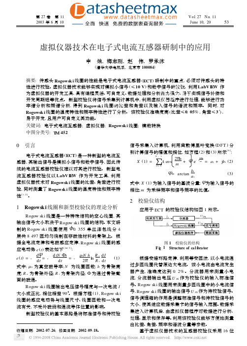
虚拟仪器技术在电子式电流互感器研制中的应用申 烛,梅志刚,赵 伟,罗承沐(清华大学电机系,北京市100084)摘要:传感头Rogowsk i 线圈的性能是电子式电流互感器(ECT )研制中的重点,必须对传感头的特性进行校验。
虚拟仪器技术能够实现对模拟小信号(≤10V )和数字信号的校验。
利用LabV I E W 作为虚拟仪器的开发工具,具有编程灵活、可自定义、数据处理和分析能力强大、易于实现信号补偿和开发周期短等优点。
新型校验仪将信号采集到计算机中,利用虚拟仪器程序进行处理,能够进行功率谱分析和频谱分析,得到Rogowsk i 线圈的比差和角差以及输入信号的谐波和频率。
同时,对Rogowsk i 线圈的温度特性和频率特性进行了分析。
该校验仪准确度高(比差≤0.05%,角差≤3′),易于开发,且用户可自定义其功能。
关键词:电子式电流互感器;虚拟仪器;Rogowsk i 线圈;模数转换中图分类号:T M 452收稿日期:2002-07-26;修回日期:2002-09-18。
0 引言电子式电流互感器(ECT )是一种新型的电流互感器,其输出信号是模拟小信号和数字信号,因此传统的电流互感器校验仪难以对其进行校验。
新型电流互感器校验仪以LabV I E W 作为开发工具,利用虚拟仪器技术对Rogowsk i 线圈的比差、角差进行校验,同时测量了Rogowsk i 线圈的温度特性和频率特性[1,2]。
1 Rogowsk i 线圈和新型校验仪的理论分析Rogow sk i 线圈是一种特殊结构的空心线圈,其输出信号大小取决于Rogow sk i 线圈的结构。
本文研制的Rogow sk i 线圈使用<0.355单丝漆包线分4层共8497匝均匀绕制在非磁性材料的骨架上。
根据全电流定律和电磁感应定律,Rogow sk i 线圈的感应电动势e (t )表达如下[3~5]:e (t )=-d Υd t =-d (N 5)d t =-Λ0N h 2ΠlnR a R i d I d t(1)式中:Λ0为真空磁导率;N 为线圈匝数;h 为骨架高度;R a 为骨架外径;R i 为骨架内径;5为通过骨架截面的磁通。

基于LabView的电流互感器励磁特性自动测量系统程玉进;达来;杨煜普;李富根;张毅君;牛志永【期刊名称】《微型电脑应用》【年(卷),期】2004(020)010【摘要】电流互感器二次绕组的励磁特性是决定互感器性能的重要因素,二次绕组品质的好坏直接关系到成品的质量.本文介绍了互感器制造厂常用的电流互感器励磁特性的检测方法,并剖析了其缺点,结合虚拟仪器的概念提出了一种基于计算机技术的电流互感器励磁特性检测系统,并讨论了这种系统的原理及其硬件和软件实现.系统实现了电流互感器二次绕组励磁特性检测自动化,极大提高了生产效率;又具有开发周期短、成本低的特点,并且以实际测量结果展示此方法的优势.【总页数】4页(P15-18)【作者】程玉进;达来;杨煜普;李富根;张毅君;牛志永【作者单位】上海交通大学自动化系,硕士研究生,上海,200030;上海交通大学自动化系,硕士研究生,上海,200030;上海交通大学自动化系,教授博士生导师,上海,200030;上海MWB互感器有限公司,工程师,上海,200245;上海MWB互感器有限公司,工程师,上海,200245;上海MWB互感器有限公司,工程师,上海,200245【正文语种】中文【中图分类】TP3【相关文献】1.一种基于广义逆的电流互感器励磁特性分析方法 [J], 王一清;阮江军;杨志强2.基于人工神经网络的电流互感器励磁特性建模方法 [J], 于海春;俞阿龙3.基于LabVIEW的换能器辐射声场自动测量系统 [J], 王伟印;陈毅;王世全;贾广慧4.基于超低频任意波形信号源进行保护用电流互感器励磁特性试验新方法 [J], 刘涛;刘可真;梁仕斌;李秉睿5.基于LabVIEW的甲烷产气量自动测量系统设计 [J], 姚燕;邱倩;沈晓敏;金佩薇;梁晓瑜;朱颖颖因版权原因,仅展示原文概要,查看原文内容请购买。
基于LabVIEW平台的光电互感器校验仪设计许江淳;石河;李瑞;张松琛;赵晔【摘要】为了解决现有光电互感器校验系统在精度和稳定性上的不足,该文设计了一种基于LabVIEW平台的光电互感器校验仪.系统由前瑞信号处理模块、采集卡和LabVIEW平台上位机软件组成,采用IEC61850协议实现数据通信,通过直接比较被测试互感器信号和标准互感器信号,实现被测互感器比差和角差的测量.实验结果表明系统测量精度高于0.5‰,能够完成对0.02级光电互感器的校验,在甘肃某330 kV数字化变电站进行了现场测试,系统稳定性满足要求.【期刊名称】《工业仪表与自动化装置》【年(卷),期】2016(000)003【总页数】4页(P118-121)【关键词】光电互感器;校验仪;LabVIEW;IEC61850;直接比较法【作者】许江淳;石河;李瑞;张松琛;赵晔【作者单位】昆明理工大学信息工程与自动化学院,昆明650500;昆明理工大学信息工程与自动化学院,昆明650500;昆明理工大学信息工程与自动化学院,昆明650500;昆明理工大学信息工程与自动化学院,昆明650500;昆明理工大学信息工程与自动化学院,昆明650500【正文语种】中文【中图分类】TM76随着数字化变电站的推广与应用,光电互感器得到了迅速的发展。
光电互感器的变换原理区别于传统电磁式互感器,其二次输出可分为模拟量和数字量两类[1]。
在使用过程中,互感器输出量的准确度必须经过校验。
因此,实现对光电互感器的准确校验已成为数字化变电站中的一项关键技术。
为解决现有光电互感器校验系统在精度和稳定性上的不足,该文设计了一种基于LabVIEW平台的新式光电互感器校验仪,通过直接比较法实现被测信号比差和角差的测量。
系统由前端信号处理模块、NI-4474采集卡和LabVIEW平台上位机软件组成,其中前端信号处理模块主要完成信号滤波放大功能,NI-4474采集卡完成信号采样与上传,上位机软件实现IEC61850协议解析和互感器误差测量。
基于LabVIEW的先进仪器系统4.6 通用信号调理功能无论所使用的传感器或换能器是什么类型,适当的信号调节设备可以提高该系统的质量和性能。
信号调理功能对所有类型的信号都非常有用,包括放大,滤波和隔离信号。
4.6.1扩增不必要的噪音对基于PC的数据采集系统的测量精度是一场浩劫。
信号调理放大电路,它适用于电脑机箱外,并靠近信号源的增益,可以提高测量的分辨率和有效地减少噪声的影响。
一个放大器,不论位置是直接接在DAQ板卡或者是基于外部信号条件,都可以在ADC信号转换为数字值之前获得增益小信号。
升压输入信号尽可能多的利用ADC的输入范围。
然而,许多传感器产生的电压输出信号是毫伏甚至微伏的量级。
这些低级的模拟信号可以直接在DAQ板卡放大,也可以从信号导线或电脑机箱内放大任何选择的噪音信号。
当输入信号小到微伏,这个噪声会淹没了信号本身,就会导致无意义的数据。
为减少对信号系统噪声影响的简单方法是对尽可能靠近源的信号进行放大,在可能会损坏信号的噪音进入导线或电脑机箱之前,提高模拟信号的电压高于噪音信号。
例如,一个J型热电偶输出一个级别非常低的以50μV/℃改变电压值的信号。
4.6.2过滤和平均过滤器是用来屏蔽在一定频率范围内不必要的噪音。
许多系统将展出来自源60Hz的周期性噪声等组件作为电源或动作。
低通滤波器信号调理电路可以消除不需要的高频分量。
但是,一定要慎重选择滤波器的带宽,这样信号的响应时间可以不受影响。
尽管许多信号调节器包括低通噪声滤波器可以消除不必要的噪音,但还要采取另外的预防措施,即使用软件平均法去除额外的噪声。
软件平均法是数字滤波获取读数简单而有效的方法;对于所需的每个数据点,数据采集系统采集和平均多个电压读数。
例如,一个常见的方法是获取100点,为每个需要的测量量取平均值。
4.6.3隔离数据采集系统的接地不当是测量问题和损坏DAQ板卡最常见的原因。
隔离信号调节器可以通过将信号从源到测量设备通过没有电或物理连接来防止这些大部分问题。
基于LabVIEW的电流互感器校验仪Xin Ai Hai Bao T. H. Song---布鲁塞尔大学2004摘要:虚拟仪器(VI),指的是利用软件在计算机上建立各种各样的仪器,比如说Labview,就象是真的建立在计算机上的仪器一样。
其主要特点是多功能的,可以集成多种功能于一台PC上,从而使其性能高,成本底。
在我所讲的这一章中,Labview虚拟仪器技术应用于测试与测量仪器电流互感器(AT)。
利用Labview测量仪器电流互感器精度校准精度是相当高的。
这个虚拟的电流互感器校验仪不仅能够自动的进行尺寸计算,而且还能够指出错误的状态曲线。
关于基于Labview的电流互感器校验仪的测试表明,它不仅能够用于替代传统的校验仪,而且还能够比传统的检验仪做的更好。
关键字:电流互感器(AT) AT校验仪虚拟仪器 LabviewI. 简介自从1992年美国建立VXIbus Rw.1.1标准以及National Instruments公司出品Labview 软件以后,虚拟仪器已经为他们商业上奠定了基础,虚拟仪器扮演的主要角色就是利用软件来构建各种仪器。
大多数的传统的仪器都能够通过虚拟仪器来实现,虚拟仪器的通过PC来实现的真实可用的仪器。
虚拟的电流互感器被广泛的应用于各种各样的电流测量,并且它还具有保护功能,能隔离和扩大测量范围。
随着业务的快速发展计算机测量与控制技术,与相继出现的电流互感器和transduczr ,有越来越多的高accuracv和低secondarly 电流的电流变压器。
电流变压器的标准电流通常是1A或者5A,而一些不标准的电流变压器有可能是0.1A或者更底。
虽然我们有技术,使这种校验方式硬件如单片计算机和电子电路,DSP等[集成电路],但是这将耗资太大钱,为这些不符合标准的校准器,并会采取过多的时间来校准所作出的这些硬件,这样不理想,所以无论从功能性和实用性都要求设计各种新的电流变压器(AT)。
基于LabVIEW的互感器测试数据管理系统设计
赵艳华;张伟;严松;徐伟;谢启
【期刊名称】《工业控制计算机》
【年(卷),期】2014(027)007
【摘要】开发了一套基于虚拟仪器技术的互感器测试数据管理系统.系统由工控机、多功能数据采集卡等硬件,结合在Lab-VIEW 7虚拟仪器平台上开发的软件组成,开发了独立的数据管理系统.简要论述了测试数据管理系统的硬件组成和选择原则,对
测试数据管理系统软件的设计思想和结构进行详细的介绍.该数据管理系统能对互
感器测试数据进行安全、准确、可靠的管理,具有抗干扰能力强和操作简单等特点.【总页数】2页(P65,158)
【作者】赵艳华;张伟;严松;徐伟;谢启
【作者单位】常熟理工学院电气与自动化工程学院,江苏常熟215500;常熟理工学
院电气与自动化工程学院,江苏常熟215500;常熟理工学院电气与自动化工程学院,
江苏常熟215500;常熟理工学院电气与自动化工程学院,江苏常熟215500;常熟理
工学院电气与自动化工程学院,江苏常熟215500
【正文语种】中文
【相关文献】
1.基于 Labview 的超导腔测试数据采集系统 [J], 张娟;戴建枰;黄泓;徐波;林海英;孙毅;潘卫民
2.基于互感器误差测试数据的计算机网络分析与探讨 [J], 韩小涛
3.基于LabVIEW的继电器测试数据查询系统 [J], 关华云;何平
4.基于Labview的光耦测试数据库验证系统研究 [J], 周兆庆;吴凯;曹玉保
5.基于LabVIEW的振动测试数据采集分析软件平台设计与实现 [J], 梁忠仔;黄丹羽;姜金辉;张梁;任小梦
因版权原因,仅展示原文概要,查看原文内容请购买。
附录A LabVIEW Based Instrument Current Transformer CalibratorXin Ai Hal Bao Y.H. Song1) NorthChinaElectricPowerUniversity, Beijing, China 1072062) BrunelUniversity. UKABSTRACTThe Virtual Instrument (VI) mainly refers to build all kinds of instruments by software such as LabVIEW, which likes a real instrument build in a computer. Its' main characteristics are flexibility, multi-functions, multiple uses for one PC computer, giving high performance, and is less costly. In this paper, the VI technology is applied to the test and measurement of instrument current transformer (TA). By using the LabVIEW, the TA accuracy calibrator was developed. This virtual T.4 calibrator can automatically measure the accuracy of T.4 and can indicate the ratio error and phase error curves. The tests and calibration for the TA show that the virtual TA calibrator can be used in place of the traditional calibrator and is much better than the traditional one. Keywords:Instrument current transformer (TA), TA calibrator, Virtual Instruments, LabVIEW.I. INTRODUCTIONSince 1992 the VXIbus Rev.1.4 standard was established by the United States and LabVIEW was presented by the National Instruments co.(Nl), the Virtual Instrument (VI) have lain the foundation for its commercial use. The main characteristic of Virtual Instrument is that it makes instruments by software. Most of the traditional instrument can be developed by VI. The VI is a real instrument made by the personal computer.The Instrument current transformer (TA) is widely used in all kinds of current measurement and it has the functions of protection, isolation and extending the measuring range. With the rapid development of computer measurement and control technology, and with the sequent emergence of current transformer and transducer, there is an increasing number of current transformers with high accuracy and low secondary current. The standard TA secondary current is usually 1A or 5A: some non-standard TA secondary current may be 0 1A or lower. Although we have the technique to make this kind of calibrator by means of hardware such as single chip computer and electroniccircuit, DSP and so on, it will cost too much money for these no-standard calibrator and will take too much time and the calibrator made by these hardware mill not be satisfactory in both function and practicality for designing all kinds of new TA.The calibrator that adopts VI technology not only can meet the requirements of the traditional one but also can satisfy customers with such advantages as multi-functions, convenience, and high ratio between performance and cost. The experiment results indicate that the virtual calibrator can provide excellent condition for TA measurement and design. The VI technology and personal computer must be widely used in the area of calibration on instrument transformer.Ⅱ. THE WORKING PRINCIPLE OF TA CALIBRATOR The error of TA includes ratio error and phase error. The measuring of the error of TA or the calibration of the accuracy of TA usually applies differential measuring method. The method needs a standard TA except the measured TA and a TA calibrator. There is the same turn ratio between the standard and measured T4 and the standard TA's accuracy should be 2 levels higher than the measured one. The calibrator function lies in forming comparison circuits, measuring, and showing the error at all range. The comparison circuit, also referred to the difference measuring principle circuit, is showed in Fig. 1. By measuring the voltage on I, and Rd, calculate the corresponding current. Then the calibrator can indicate the error.When a TA has the same turn ratio between the primary and secondary winding, the self-comparison circuit could be used and is shown in Fig.2. In the figures, TA0 and TAX are standard and TA being measured respectively. Np and Ns are primary and secondary winding turns. ip and io, id, i, are primary current secondary standard current, secondary error current, secondary current of TA being measured respectively. Ro and R,R, are secondary winding's resistance ofstandard TA, error current detecting resistance, burden resistance of TA being measured respectively. To and K, Tb. T, are voltage sampling points which can calculate the current In this paper, only voltage between K and T, voltage between Tb and T, are being measured and they represent the voltage on R, and R, respectively.In general, the TA calibrator's principle of the sample resistance should be:1)it can not affect the accuracy of the comparison circuit. In the ideal condition R, and Rd should be 0, but it can not be sampled. So there must be sample resistance, in this paper, R, as shown in Fig, is used;1)the magnitude of the sample resistance should make the sampled standard currentand error current in pro rata and should not have too much difference. The sampled resistance is set by experiment: R, is the secondary standard current sampling resistance and can be 0.1-0.50, R, is the error current sampling resistance and can be, R, is the burden resistance and it depends on the TA being measured. E$ sampling the voltage uo and U, on R, and R, respectively, the ratio error and phase error are showed on the LED through some process and calculations.According to the TA error's phase diagram, when io is maximum, the value of id is the ratio error; when io changes from negative to positive and equals to 0, the value of id is the phase error. For the same principle, the relationship is equal to the voltage signal U, and ud. showed in Fig.3. a and b is represent the ratio error and phase error separately. the TA's real ratio error C and phase error 6 can be found out through proper calculation,Where U, is the amplitude of uo The T.4 calibrator doesn't need very high accuracy. 1% to 3% error for the calibrator is enough. Because of the difference measuring principle, the error is the read error of calibrator, that is, the TA's error's error being measured. But the calibrator needs to have a suitable enlargement factor. The calibrator maximum enlargement factor through all channels should be 1000 times.III. THE PRINCIPLE OF VIRTUAL CA LIBRATORThe Virtual Instrument consists of three parts: the external comparison circuit (showed in Fig.1 or Fig.2), data acquisition card (PCI-6023) installed in the PC and the VI program by LabVIEW Then, after the two channels' signal U, and ud come into the PC through the ADC, the rest of the work is done by the software. In this paper we use voltage U, on R, substitute for U, approximatively. The virtual calibrator's work flow chart is shown as follow:1) Set the essential initial values of the virtual calibrator;2) Press the start button to start to work, adjusting the voltage regulator and changing the primarycurrent, let the ratio between primary current and the rated current change from10% to 120%;3) The VI program will group the voltage signal U, and ud , then use the digital filter to eliminatethe harmonic:4) Calculate the root-mean-square (RMS) value of tlx and 14, find out the amplitude of 21;5) Calculate the RMS valve of io (substitute for f, ), i, and the ratio between io and it's rated current and show the results.6) Find out the a and b showed in Fig. 3, calculate the ratio error and phase error and show the results.7) Set the L times loop, record and show the errors acquired by every time,8) Show and print all the results of calibration.9)Stop.The front panel of the virtual calibrator has the Controls, indictor and Switch. The function of Controls is to set the initial value before it works, The function of the Indictor is to show at1 kinds of needed values, including digital, curve and diagram etc.. 'The switch decides the start and stop of the virtual calibrator.Of course, to change the measuring range, the operator needs to adjust the voltage regulator and change the primary current. This operation is necessary like that of the traditional calibration, but the recording for the error in any range is done by the virtual calibration. This confirms the accuracy of recording and relieves the operator's work. The use of virtual calibrator is most interesting.The controls of virtual calibrator include:1) Setting the two sampling (analogue input) channels;2) Setting the magnitude of sampling resistance in the comparison circuit;3) Setting the secondary rated current of measured TA;4) Setting the number of sampling of error curve;The Indictor of virtual calibrator has:1) Showing ratio and phase error, ratio between the primary current and the rated ones in digital;2) Showing ratio and phase error, ratio between the primary) current and the rated ones In curvesand diagram, where the curve include the active sampling points and function fitting curves; 3) Showing the error for the ratio between the primary current and the rated current from 10% to 1 20°%;4) Showing the waveform of standard and error current, digital value of amplitude;5) Showing of digita1 RMS value the standard and error current;6) Showing the pole of TA in the comparison circuit;The above shows that the function of virtual calibrator is greatly expended that of the traditional ones. 7111s kind of calibrator is not only convenient to use, but also makes the performance of the calibrator much better. From the function that shows the waveform, we can find out if there are some harmonics in the current, and confirm the accuracy for the calibrator.IV. EXPERIMENTThe virtual calibrator is mainly characterized by the flexibility compared with the traditional ones. Although the front panel has many functions, they can be easily extended by the user. So the virtual calibrator is of important value for the non-standard TA calibration.In the experiment, the primary current produce by a step-up current transformer and its' current controlled by a voltage regulator. Through fitting the comparison circuit, the measuring range of the virtual calibrator can be set in any value. This pap er gives SA and 0.1A two kinds of TA’s calibration experiment. The parameter and method, results are presented below.A. 5A TA experimentThe parameter of TA being measured is:Because of the 1:1 ratio of turn, the calibration for it doesn't need standard TA. The calibration circuit show in Fig2 We can apply self calibration method to measure it’s accuracy. The results are presented in the Ftg.4 and Fig5 and show that this TA's accuracy can be defined as 0.5 degree.B. 0.1A TA experimentThe parameter of standard TA:From the Fig4 and 5, the accuracy of the TA being measured can be defined as 0.5 degree. In the experiment, the input signal of virtual calibrator should be properly grounded to avoid the disturbance. The sampling resistance in the comparison circuit should use precise ones and with no induction.V. CONCLUSIONSThe VI technique is one of the new scientific and technique productions. The appearance of VI is called“Revolution of Measuring and Control Technology”. According to the dev elopment of the software and hardware for computers, the VI t~hn01Ogy will have more developing space. The VIS will replace most of the traditional ones in the 21th century. With its flexibility, the virtual calibrator can measure any kind of T.4 including standard and non-standard ones. But the traditional calibrator can not measure most of the non-standard TA. It can record and save, display the data automatically. The method presented in this paper gives a new way to make he TA calibration. The main characteristics of the virtual calibrator are:1) Flexibility, virtual calibrator is mainly made of LabVIEW software and can be easily modifiedby rewrite some software;2.) Multi function, VI is designed on PC. It has waveform indictor, parameter controls and so on.At the time we calibrating a TKs accuracy, these functions can indicate many information such as waveform quality and so on;3) Convenience to carry and use;4) High efficiency and accuracy.;5) High ratio between performance and cost;6) For multiple use in one PC.7) It can record and save, display the calibration data automatically.基于LabVIEW的电流互感器校验仪Xin Ai Hai Bao T. H. Song---布鲁塞尔大学摘要虚拟仪器(VI),指的是利用软件在计算机上建立各种各样的仪器,比如说LabVIEW,就象是真的建立在计算机上的仪器一样。