The Thermal Fin (“Tfin”) Problem
- 格式:pdf
- 大小:1.45 MB
- 文档页数:5


界面层热膨胀系数不匹配英文回答:The issue of mismatched coefficients of thermal expansion in the interface layer can cause various problems in engineering and manufacturing processes. The coefficient of thermal expansion (CTE) is a measure of how much a material expands or contracts when its temperature changes. When two materials with different CTEs are joined together, such as in a layered structure or a bonded joint, the difference in expansion or contraction rates between the two materials can lead to stress and strain.This mismatch in CTEs can result in several issues. One common problem is the development of cracks or delamination at the interface layer. As the temperature changes, the materials expand or contract at different rates, leading to the accumulation of stress at the interface. Over time,this stress can exceed the strength of the bond or the material itself, causing cracks to form or the layers toseparate.Another issue that can arise from mismatched CTEs is dimensional instability. If a structure or component is designed with materials that have significantly different expansion or contraction rates, it can lead to dimensional changes when exposed to temperature variations. For example, consider a metal frame with a glass panel attached to it.If the CTE of the metal is much higher than that of the glass, the frame will expand or contract more than the glass, causing the glass to crack or the frame to deform.To mitigate the effects of mismatched CTEs, several strategies can be employed. One approach is to use intermediate layers or interlayers with CTEs that arecloser to the average of the two materials being joined. These interlayers act as a buffer, absorbing some of the stress and strain caused by the temperature changes. Additionally, the use of compliant materials or flexible joints can help accommodate the differential expansion or contraction between the materials.In some cases, it may be necessary to select materials with similar CTEs to ensure compatibility. For example, when designing a composite structure, it is important to choose reinforcing fibers and matrix materials with similar CTEs to prevent delamination or dimensional instability. Similarly, in electronic packaging, selecting materials with similar CTEs can help reduce the risk of failure due to thermal cycling.中文回答:界面层热膨胀系数不匹配的问题在工程和制造过程中可能会引发各种问题。

User’s GuideROHM Solution SimulatorDC/DC Converter BD9G500EFJ-LA Thermal SimulationThis document contains electrical simulations of the DC/DC converter BD9G500EFJ-LA and introduces and describes the use of a simulation environment that allows simultaneous thermal simulation of devices including Schottky Barrier Diodes (SBD: RB088BM100TL). By changing the parameters of the components, it is possible to simulate a wide range of conditions.1 Simulation circuitFigure 1. Simulation circuit (BD9G500EFJ-LA)In Figure 1, the area within the green line shows the thermal simulation circuit and the rest of the figure shows the electrical simulation circuit.This circuit is an application circuit based on a 1-channel buck DC/DC converter with a current output of up to 5 A using the BD9G500EFJ-LA.The thermal simulation circuit feeds the device losses and SBD losses calculated in the electrical simulation into the thermal simulation model, and calculates the IC and SBD temperatures.2 Simulation methodSimulation settings such as simulation time and convergence options can be set from “Simulation Settings” shown in Figure 2, and the initial simulation settings are shown in Table 1.If you are having problems with the convergence of the simulation, you can change the advanced options to fix the problem. The simulation temperature and various parameters of the electrical circuit are defined in “Manual Options”.Figure 2. Simulation Settings and executionTable 1. Initial values for Simulation SettingsParametersInitial valuesRemarksSimulation Type Time-Domain Do not change the simulation type End time7 msecs Advanced Options More SpeedManual Options .PARAM …See Table 2 for details3 Simulation conditions3.1 Definition of parametersThe parameters for the components shown in blue in Figure 3 are defined in the manual options as they need to be set in the simulation conditions. Table 2 shows the initial values for each parameter. These values are written in a text box in the “Manual Options” section of the simulation settings, as shown in Figure 4.Figure 3. Definition of component parametersSimulation SettingsSimulateTable 2. Simulation conditionsParameters VariablenamesInitial values Unit DescriptionTemperature Ta25°C Ambient temperatureVoltage V_VIN48V Input voltage Set in the range of 7 to 76 VVoltage V_VOUT5V Output voltage Set in the range of 1 V to (0.97 × V_VIN)Current I_IOUT1A Output current 5 A (MAX)Inductance L_PRM33µH Smoothing inductorFigure 4. Definition of parameters3.2 Setting of component constantsFor the method of setting switching frequency, output LC filter constant, output voltage, etc., refer to “Selection of Components Externally” in the data sheet or the calculation sheet.BD9G500EFJ-LA Data sheetCalculation-Sheet For The Circuit Theoretical Formula – BD9G500EFJ-LAWrite parameters3.3 Thermal circuitThe “BD9G500EFJ_LA” symbol in Figure 5 is the thermal simulation model of the BD9G500EFJ-LA. The nodes shown inred in Figure 5 can be used to check the temperature of the junction, the mold surface and the FIN surface. Detailedinformation for each node is shown in Table 3.You can check the temperature bytouching the red node with a probeFigure 5. BD9G500EFJ-LA thermal simulation modelTable 3. Description of the nodes in Figure 5Node name DescriptionBD9G500EFJ_Tj Monitors the junction temperature of BD9G500EFJ-LASBD_Tj Monitors the junction temperature of RB088BM100BD9G500EFJ_Tt Monitors the top center temperature of BD9G500EFJ-LASBD_Tt Monitors the top center temperature of RB088BM100SBD_Tfin Monitors the FIN center temperature of RB088BM1003.4 Selecting a thermal simulation modelThere are a number of thermal simulation models to choose from and their components are shown in Table 4. Figure 6 shows how to select one. First, right-click on the BD9G500EFJ-LA component and select “Properties”. In the “Property Editor”, set the value of the “SpiceLib Part” to the value you selected from Table 4 to change the thermal simulation model.Figure 6. How to select a thermal simulation modelTable 4. List of available componentsComponent name SpiceLib Part valueDescriptionBD9G500EFJ-LA2s Thermal simulation model for a two-layer board 2s2pThermal simulation model for a four-layer boardFor more information on the board, see “Reference: About the BD9G500EFJ-LA thermal simulation model” on page 7.Changing the value of the SpiceLib Part allows you to select a different thermal model4 Links to related documents4.1 ProductsBD9G500EFJ-LARB088BM1004.2 User’s GuideSingle Buck Switching Regulator BD9G500EFJ-LA EVK User’s GuideReference: About the BD9G500EFJ-LA thermal simulation modelAn image of the 3D model used to create the thermal simulation model is shown in Figure A. Structural information is also shown in Table A.Figure A. BD9G500EFJ-LA 3D imageTable A. Structural informationStructural parts DescriptionBoard outline dimensions114.3mm × 76.2mm, t=1.6mmBoard material FR-4Layout pattern Refer to “Single Buck Switching Regulator BD9G500EFJ-LA EVK User’s Guide”2-layer board Layer structure Top Layer : 70µm ( 2oz ) Bottom Layer : 70µm ( 2oz )4-layer board Layer structure Top Layer : 70µm ( 2oz )Middle1 & Middle2 Layer : 35µm ( 1oz ) Bottom Layer : 70µm ( 2oz )BD9G500EFJ-LA (HTSOP-J8)RB088BM100 (TO-252)BoardNoticeROHM Customer Support System/contact/Thank you for your accessing to ROHM product informations.More detail product informations and catalogs are available, please contact us.N o t e sThe information contained herein is subject to change without notice.Before you use our Products, please contact our sales representative and verify the latest specifica-tions :Although ROHM is continuously working to improve product reliability and quality, semicon-ductors can break down and malfunction due to various factors.Therefore, in order to prevent personal injury or fire arising from failure, please take safety measures such as complying with the derating characteristics, implementing redundant and fire prevention designs, and utilizing backups and fail-safe procedures. ROHM shall have no responsibility for any damages arising out of the use of our Poducts beyond the rating specified by ROHM.Examples of application circuits, circuit constants and any other information contained herein areprovided only to illustrate the standard usage and operations of the Products. The peripheral conditions must be taken into account when designing circuits for mass production.The technical information specified herein is intended only to show the typical functions of andexamples of application circuits for the Products. ROHM does not grant you, explicitly or implicitly, any license to use or exercise intellectual property or other rights held by ROHM or any other parties. ROHM shall have no responsibility whatsoever for any dispute arising out of the use of such technical information.The Products specified in this document are not designed to be radiation tolerant.For use of our Products in applications requiring a high degree of reliability (as exemplifiedbelow), please contact and consult with a ROHM representative : transportation equipment (i.e. cars, ships, trains), primary communication equipment, traffic lights, fire/crime prevention, safety equipment, medical systems, servers, solar cells, and power transmission systems.Do not use our Products in applications requiring extremely high reliability, such as aerospaceequipment, nuclear power control systems, and submarine repeaters.ROHM shall have no responsibility for any damages or injury arising from non-compliance withthe recommended usage conditions and specifications contained herein.ROHM has used reasonable care to ensur e the accuracy of the information contained in thisdocument. However, ROHM does not warrants that such information is error-free, and ROHM shall have no responsibility for any damages arising from any inaccuracy or misprint of such information.Please use the Products in accordance with any applicable environmental laws and regulations,such as the RoHS Directive. For more details, including RoHS compatibility, please contact a ROHM sales office. ROHM shall have no responsibility for any damages or losses resulting non-compliance with any applicable laws or regulations.W hen providing our Products and technologies contained in this document to other countries,you must abide by the procedures and provisions stipulated in all applicable export laws and regulations, including without limitation the US Export Administration Regulations and the Foreign Exchange and Foreign Trade Act.This document, in part or in whole, may not be reprinted or reproduced without prior consent ofROHM.1) 2)3)4)5)6)7)8)9)10)11)12)13)。
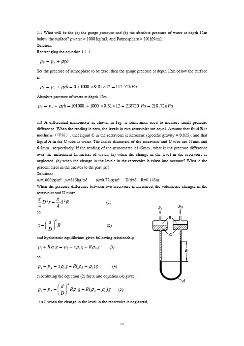
1.1 What will be the (a) the gauge pressure and (b) the absolute pressure of water at depth 12mbelow the surface? ρwater = 1000 kg/m3, and Patmosphere = 101kN/m2.Solution:Rearranging the equation 1.1-4gh p p a b ρ+=Set the pressure of atmosphere to be zero, then the gauge pressure at depth 12m below the surfaceiskPa gh p p a b 72.1171281.910000=⨯⨯+=+=ρAbsolute pressure of water at depth 12mkPa Pa gh p p a b 72.2182187201281.91000101000==⨯⨯+=+=ρ1.3 A differential manometer as shown in Fig. is sometimes used to measure small pressuredifference. When the reading is zero, the levels in two reservoirs are equal. Assume that fluid B ismethane (甲烷), that liquid C in the reservoirs is kerosene (specific gravity = 0.815), and thatliquid A in the U tube is water. The inside diameters of the reservoirs and U tube are 51mm and6.5mm , respectively. If the reading of the manometer is145mm., what is the pressure differenceover the instrument In meters of water, (a) when the change in the level in the reservoirs isneglected, (b) when the change in the levels in the reservoirs is taken into account? What is thepercent error in the answer to the part (a)?Solution :p a =1000kg/m 3 p c =815kg/m 3 p b =0.77kg/m 3 D/d=8 R=0.145mWhen the pressure difference between two reservoirs is increased, the volumetric changes in the reservoirs and U tubesR d x D 2244ππ= (1) so R D d x 2⎪⎭⎫ ⎝⎛= (2) and hydrostatic equilibrium gives following relationshipg R g x p g R p A c c ρρρ++=+21 (3)sog R g x p p c A c )(21ρρρ-+=- (4)substituting the equation (2) for x into equation (4) givesg R g R D d p p c A c )(221ρρρ-+⎪⎭⎫ ⎝⎛=- (5) (a )when the change in the level in the reservoirs is neglected,()Pa g R g R g R D d p p c A c A c 26381.98151000145.0)()(221=⨯-=-≈-+⎪⎭⎫ ⎝⎛=-ρρρρρ(b )when the change in the levels in the reservoirs is taken into account ()Pa g R g R D d g R g R D d p p c A c c A c 8.28181.98151000145.081.9815145.0515.6)()(22221=⨯-+⨯⨯⨯⎪⎭⎫ ⎝⎛=-+⎪⎭⎫ ⎝⎛=-+⎪⎭⎫ ⎝⎛=-ρρρρρρ error=%=7.68.2812638.281- 1.4 There are two U-tube manometers fixed on the fluid bed reactor, as shown in the figure. The readings of two U-tube manometers are R 1=400mm ,R 2=50mm, respectively. The indicating liquid is mercury. The top of the manometer is filled with the water to prevent from the mercury vapor diffusing into the air, and the height R 3=50mm. Try to calculate the pressure at point A and B .Solution: There is a gaseous mixture in the U-tube manometer meter. The densities of fluids are denoted by Hg O H g ρρρ,,2, respectively. The pressure at point A is given by hydrostatic equilibriumFigure for problem 1.4g R R g R g R p g Hg O H A )(32232+-+=ρρρg ρis small and negligible in comparison with Hg ρand ρH2O , equation above can be simplifiedc A p p ≈=232gR gR Hg O H ρρ+=1000×9.81×0.05+13600×9.81×0.05=7161N/m²1gR p p p Hg A D B ρ+=≈=7161+13600×9.81×0.4=60527N/m1.5 Water discharges from the reservoir through the drainpipe, which the throat diameter is d. The ratio of D to d equals 1.25. The vertical distance h between the tank A and axis of the drainpipe is 2m. What height H from the centerline of the drainpipe to the water level in reservoir is required for drawing the water from the tank A to the throat of the pipe? Assume that fluid flow is a potential flow. The reservoir, tank A and the exit ofdrainpipe are all open to air.Solution: Bernoulli equation is written between stations 1-1 and 2-2, with station 2-2 being reference plane: 2222222111u gz p u gz p ++=++ρρ Where p 1=0, p 2=0, and u 1=0, simplification of the equation22u Hg =1The relationship between the velocity at outlet and velocity u o at throat can be derived by the continuity equation:22⎪⎭⎫ ⎝⎛=⎪⎪⎭⎫ ⎝⎛D d u u o 22⎪⎭⎫ ⎝⎛=d D u u o 2 Bernoulli equation is written between the throat and the station 2-23 Combining equation 1,2,and 3 givesSolving for HH=1.39m1.6 A liquid with a constant density ρ kg/m 3 is flowing at an unknown velocity V 1 m/s through a horizontal pipe of cross-sectional area A 1 m 2 at a pressure p 1 N/m 2, and then it passes to a section of the pipe in which the area is reduced gradually to A 2 m 2 and the pressure is p2. Assuming no friction losses, calculate the velocities V 1 and V 2 if the pressure difference (p 1 - p 2) is measured. Solution :In Fig1.6, the flow diagram is shown with pressure taps to measure p 1 and p 2. From the mass-balance continuity equation , for constant ρ where ρ1 = ρ2 = ρ,222200u u p =+ρ()===144.281.92100081.910002125.11112442-⨯⨯⨯--⎪⎭⎫ ⎝⎛==ρρg h d D u Hg2112A A V V = For the items in the Bernoulli equation , for a horizontal pipe,z 1=z 2=0Then Bernoulli equation becomes, after substituting 2112A A V V = for V 2, ρρ22121211212020p A A V p V ++=++ Rearranging,2)1(21212121-=-A A V p p ρ ⎥⎥⎦⎤⎢⎢⎣⎡-⎪⎪⎭⎫ ⎝⎛-12221211A A p p V ρ=Performing the same derivation but in terms of V 2,⎥⎥⎦⎤⎢⎢⎣⎡⎪⎪⎭⎫ ⎝⎛--21221212A A p p V ρ=1.7 A liquid whose coefficient of viscosity is µ flows below the critical velocity for laminar flow in a circular pipe of diameter d and with mean velocity V . Show that the pressure loss in a length of pipe L p ∆ is 232d V μ. Oil of viscosity 0.05 Pas flows through a pipe of diameter 0.1m with a average velocity of 0.6m/s.Calculate the loss of pressure in a length of 120m.Solution :The average velocity V for a cross section is found by summing up all the velocities over the cross section and dividing by the cross-sectional area1From velocity profile equation for laminar flow2 substituting equation 2 for u into equation 1 and integrating3rearranging equation 3 gives1.8. In a vertical pipe carrying water, pressure gauges areinserted at points A and B where the pipe diameters are0.15m and 0.075m respectively. The point B is 2.5m belowA and when the flow rate down the pipe is 0.02 m 3/s, thepressure at B is 14715 N/m 2 greater than that at A.Assuming the losses in the pipe between A and B can be expressed as g V k 22where V is the velocity at A, find the value of k .If the gauges at A and B are replaced by tubes filled with water and connected to a U-tube containing mercury of relative density 13.6, give a sketch showing how the levels in the two limbs of the U-tube differ and calculate the value of this difference in metres.Solution:d A =0.15m; d B =0.075mz A -z B =l =2.5mQ =0.02 m 3/s,p B -p A =14715 N/m 2 Figure for problem 1.8 ⎰⎰==R R rdr u R udA A V 020211ππ⎪⎪⎭⎫ ⎝⎛⎪⎭⎫ ⎝⎛--=22014R r R L p p u L μ2032D L p p V L μ-=232d V L p μ=∆Pa d VL p 115201.01206.005.0323222=⨯⨯⨯==∆μsm d Q V V d Q AA AA /132.115.0785.002.044222=⨯===ππsm d Q V V d Q BB BB /529.4075.0785.002.044222=⨯===ππWhen the fluid flows down, writing mechanical balance equation222222AB B B AA A V k V g z p V g z p +++=++ρρ213.1253.4100014715213.181.95.2222k ++=+⨯k 638.0260.10715.14638.0525.24++=+=k 0.295making the static equilibriumgR g x g l p g R g x p Hg A B ρρρρρ+∆++=+∆+()()mm g g l p p R g H A B 7981.91260081.910005.214715-=⨯⨯⨯-=---=ρρρ1.9.The liquid vertically flows down through the tube from thestation a to the station b , then horizontally through the tube fromthe station c to the station d , as shown in figure. Two segments ofthe tube, both ab and cd ,have the same length, the diameter androughness.Find:(1)the expressions of g p ab ρ∆, h fab , g pcdρ∆and h fcd , respectively.(2)the relationship between readings R 1and R 2 in the U tube.Solution:(1) From Fanning equationFigure for problem 1.92V l h fab λ=andsoFluid flows from station a to station b , mechanical energy conservation giveshence2from station c to station dhence3From static equationp a -p b =R 1(ρˊ-ρ)g -l ρg 4p c -p d =R 2(ρˊ-ρ)g5 Substituting equation 4 in equation 2 ,thentherefore6Substituting equation 5 in equation 3 ,then7ThusR 1=R 222V d l h fcd λ=fcdfab h h =fab b a h p p+=+ρρlg fab b a h p p =+-lg ρfcddc h pp +=ρρfcd d c h p p =-ρfabh g l g R =+--'lg 1ρρρρ)(gR h fab ρρρ-'=1g R h fcd ρρρ-'=21.10 Water passes through a pipe of diameter d i=0.004 m with the average velocity 0.4 m/s, as shown in Figure.1) What is the pressure drop –∆P when water flows through the pipe length L =2 m, in m H 2O column?2) Find the maximum velocity and point r at which it occurs.3) Find the point r at which the average velocityequals the local velocity. 4)if kerosene flows through this pipe ,how do thevariables above change ?(the viscosity and density of Water are 0.001 Pasand 1000 kg/m 3,respectively ;and the viscosityand density of kerosene are 0.003 Pas and 800kg/m 3,respectively )solution:1)1600001.01000004.04.0Re =⨯⨯==μρud from Hagen-Poiseuille equation1600004.0001.024.0323222=⨯⨯⨯==∆d uL P μ m g p h 163.081.910001600=⨯=∆=ρ 2)maximum velocity occurs at the center of pipe, from equation 1.4-19max 0.5V u = so u max =0.4×2=0.8m3)when u=V=0.4m/s Eq. 1.4-172max 1⎪⎪⎭⎫ ⎝⎛-=wr r u u 5.0004.01max2=⎪⎭⎫ ⎝⎛-u V r = m r 00284.071.0004.05.0004.0=⨯== 4) kerosene:427003.0800004.04.0Re =⨯⨯==μρud Pa p p 4800001.0003.01600=='∆='∆μμFigure for problem 1.10m g p h 611.081.98004800=⨯=''∆='ρ1.12 As shown in the figure, the water level in the reservoir keeps constant. A steel drainpipe (with the inside diameter of 100mm) is connected to the bottom of the reservoir. One arm of the U-tube manometer is connected to the drainpipe at the position 15m away from the bottom of the reservoir, and the other is opened to the air, the U tube is filled with mercury and the left-side arm of the U tube above the mercury is filled with water. The distance between the upstream tap and the outlet of the pipeline is 20m.a) When the gate valve is closed, R=600mm, h=1500mm; when the gate valve is opened partly, R=400mm, h=1400mm. The friction coefficient λ is 0.025, and the lo ss coefficient of the entrance is 0.5. Calculate the flow rate of water when the gate valve is opened partly. (in m³/h)b) When the gate valve is widely open, calculate the static pressure at the tap (in gauge pressure, N/m²). l e /d ≈15 when the gate valve is widely open, and the friction coefficient λ is still 0.025.Solution :(1) When the gate valve is opened partially, the water discharge isSet up Bernoulli equation between the surface of reservoir 1—1’ and the section of pressure point 2—2’,and take the center of section 2—2’ as the referring plane, then∑+++=++21,2222121122—f h p u gZ p u gZ ρρ (a ) In the equation 01=p (the gauge pressure)222/396304.181.910004.081.913600m N gh gR p O H Hg =⨯⨯-⨯⨯=-=ρρFigure for problem 1.120021=≈Z uWhen the gate valve is fully closed, the height of water level in the reservoir can be related to h (the distance between the center of pipe and the meniscus of left arm of U tube).gR h Z g Hg O H ρρ=+)(12 (b )where h=1.5mR=0.6mSubstitute the known variables into equation b 2222_1,113.22)5.01.015025.0(2)(66.65.110006.013600V V V K d l h m Z c f =+⨯=+==-⨯=∑λ Substitute the known variables equation a9.81×6.66=2213.21000396302V V ++ the velocity is V =3.13m/sthe flow rate of water is h m V d V h /5.8813.312.0436004360032=⨯⨯⨯=⨯=ππ2) the pressure of the point where pressure is measured when the gate valve is wide-open. Write mechanical energy balance equation between the stations 1—1’ and 3-3´,then∑+++=++31,3233121122—f h p V gZ p V gZ ρρ (c ) since m Z 66.61=311300p p u Z =≈=2223_1,81.4 2]5.0)151.035(025.0[ 2)(V V V K d l l h c e f =++=++=∑λ input the above data into equation c ,9.8122V 81.4266.6+=⨯Vthe velocity is: V =3.51 m/sWrite mechanical energy balance equation between thestations 1—1’ and 2——2’, for the same situation of water level ∑+++=++21,2222121122—f h p V gZ p V gZ ρρ (d )since m Z 66.61=212103.51/0(page pressure Z u u m s p =≈≈=)kg J V K d l hc f /2.26251.3)5.01.015025.0(2)(222_1,=+⨯=+=∑λ input the above data into equationd , 9.81×6.66=2.261000251.322++p the pressure is: 329702=p1.14 Water at 20℃ passes through a steel pipe with an inside diameter of 300mm and 2m long. There is a attached-pipe (Φ60⨯3.5mm) which is parallel with the main pipe. The total length including the equivalent length of all form losses of the attached-pipe is 10m. A rotameter is installed in the branch pipe. When the reading of the rotameter is2.72m 3/h, try to calculate the flow rate in the main pipe and the total flow rate, respectively. The frictional coefficient of the main pipe and the attached-pipe is 0.018 and 0.03, respectively.Solution : The variables of main pipe are denoted by a subscript1, and branch pipe by subscript 2.The friction loss for parallel pipelines is2121S S s f f V V V h h +==∑∑The energy loss in the branch pipe is 22222222u d l l h e f ∑∑+=λ In the equation 03.02=λs m u d ml l e /343.0053.04360072.2053.01022222=⨯⨯===+∑πinput the data into equation ckg J h f /333.02343.0053.01003.022=⨯⨯=∑The energy loss in the main pipe is 333.022111121===∑∑u d l h h f f λ So s m u /36.22018.023.0333.01=⨯⨯⨯= The water discharge of main pipe ish m V h /60136.23.043600321=⨯⨯⨯=π Total water discharge ish m V h /7.60372.26013≈+=1.16 A Venturimeter is used for measuring flow of water along a pipe. The diameter of the Venturi throat is two fifths the diameter of the pipe. The inlet and throat are connected by water filled tubes to a mercury U-tube manometer. The velocity of flow along the pipe is found to beR 5.2 m/s, where R is the manometer reading in metres of mercury. Determine the loss of head between inlet and throat of the Venturi when R is 0.49m. (Relative density of mercury is 13.6). Solution:Writing mechanical energy balance equation between the inlet1 and throat o for Venturi meterf o o hg z V p g z V p +++=++22121122ρρ 1 rearranging the equation above, and set (z 2-z 1)=xf o oh xg V V p p ++-=-22121ρ 2 from continuity equationFigure for problem 1.1611221125.625V V d d V V o o =⎪⎭⎫ ⎝⎛=⎪⎪⎭⎫ ⎝⎛= 3 substituting equation 3 for V o into equation 2 gives()f f f f oh xg R h xg R h V h xg V V p p ++=++=+=++-=-94.1185.203.1903.19206.3922121211ρ 4from the hydrostatic equilibrium for manometerg x g R p p Hg o ρρρ+-=-)(1 5 substituting equation 5 for pressure difference into equation 4 obtainsf Hgh xg R gx g R ++=+-94.118)(ρρρρ 6 rearranging equation 6 kg J R R R R g R h Hg f /288.267.494.11861.12394.118)(==-=--=ρρρ1.17.Sulphuric acid of specific gravity 1.3 is flowing through a pipe of 50 mm internal diameter. A thin-lipped orifice, 10mm, is fitted in the pipe and the differential pressure shown by a mercury manometer is 10cm. Assuming that the leads to the manometer are filled with the acid,calculate (a)the weight of acid flowing per second, and (b) the approximate friction loss in pressure caused by the orifice.The coefficient of the orifice may be taken as 0.61, the specific gravity of mercury as 13.6, and the density of water as 1000 kg/m 3Solution: a)2.0501010==D D =⨯-=-=-81.9)130013600(1.0)(21g R p p Hg ρρ()s m p p D D C V o /63.231.461.056.1861.0130081.9)130013600(1.022.0161.021*******=⨯=≈⨯-⨯-=-⎪⎪⎭⎫ ⎝⎛-=ρs kg V D m /268.0130063.201.0442220=⨯⨯⨯==πρπb) approximate pressure drop=⨯-=-=-81.9)130013600(1.0)(21g R p p Hg ρρ12066.3Pa pressure difference due to increase of velocity in passing through the orificePa D D V V V V p p o 8.44882)2.01(63.213002242412222212221=-=⎪⎪⎭⎫ ⎝⎛-=-=-ρρ pressure drop caused by friction lossPa p f 5.75778.44883.12066=-=∆2.1 Water is used to test for the performances of pump. The gauge pressure at the discharge connection is 152 kPa and the reading of vacuum gauge at the suction connection of the pump is 24.7 kPa as the flow rate is 26m 3/h. The shaft power is 2.45kw while the centrifugal pump operates at the speed of 2900r/min. If the vertical distance between the suction connection and discharge connection is 0.4m, the diameters of both the suction and discharge line are the same. Calculate the mechanical efficiency of pump and list the performance of the pump under this operating condition.Solution:Write the mechanical energy balance equation between the suction connection and discharge connection 2_1,2222121122f H gp g u Z H g p g u Z +++=+++ρρ wherem Z Z 4.012=-(Pa 1052.1(Pa 1047.22_1,215241≈=⨯=⨯-=f H u u pressure gauge p pressure gauge p ))total heads of pump is m H 41.1881.9100010247.01052.14.055=⨯⨯+⨯+= efficiency of pump is N N e /=ηsince kW g QH N e 3.1360081.9100041.18263600=⨯⨯⨯==ρN=2.45kWThen mechanical efficiency %1.53%10045.23.1=⨯=η The performance of pump is Flow rate ,m³/h26 Total heads ,m18.41 Shaft power ,kW2.45 Efficiency ,%53.12.2 Water is transported by apump from reactor, which has200 mm Hg vacuum, to thetank, in which the gaugepressure is 0.5 kgf/cm 2, asshown in Fig. The totalequivalent length of pipe is200 m including all localfrictional loss. The pipeline isφ57×3.5 mm , the orificecoefficient of C o and orificediameter d o are 0.62 and 25mm, respectively. Frictional coefficient λ is 0.025. Calculate: Developed head H of pump, in m (the reading R of U pressure gauge in orifice meter is 168 mm Hg)Solution:Equation(1.6-9)Mass flow rates kg S V m o o /02.21000025.0414.312.42=⨯⨯⨯==ρ 2) Fluid flow through the pipe from the reactor to tank, the Bernoulli equation is as follows for V 1=V 2f H z gp p H +∆+-=ρ12 ∆z=10ms m Rg D d C V f /12.444.69375.062.01000)100013600(81.9168.025025162.02144000=⨯=-⨯⨯⎪⎭⎫ ⎝⎛-=-⎪⎭⎫ ⎝⎛-=ρρρ)(Pa p 7570710013.17602001081.95.054=⨯⨯+⨯⨯=∆ ∆p/ρg=7.7mThe relation between the hole velocity and velocity of pipeFriction losssoH=7.7+10+5.1=22.8m2.3 . A centrifugal pump is to be used to extract water from a condenser in which the vacuum is 640 mm of mercury, as shown in figure. At the rated discharge, the netpositive suction head must be at least 3m above the cavitation vaporpressure of 710mm mercury vacuum. If losses in the suction pipeaccounted for a head of 1.5m. What must be the least height of the liquid level in the condenser above the pump inlet?Solution :From an energy balance,WhereP o =760-640=120mmHgP v =760-710=50mmHgUse of the equation will give the minimum height H g as2.4 Sulphuric acid is pumped at 3 kg/s through a 60m length of smooth 25 mm pipe. Calculate the drop in pressure. If the pressure drop falls by one half, what will the new flowrate be ?• Density of acid 1840kg/m 3• Viscosity of acid 25×10-3 PasSolution:Velocity of acid in the pipe:s m D d V V /12112.42200=⎪⎭⎫ ⎝⎛⨯=⎪⎭⎫ ⎝⎛=m g u d l f H f 1.581.92105.0200025.02422=⨯⨯==NPSH H g p p H f v og ---=ρm NPSH H g p p H f v o g 55.335.181.9100081.913600)05.012.0-=--⨯⨯⨯-=---=(ρs m d m d mpipe of area tional cross flowrate volumetric u /32.3025.01840785.03785.04sec 222=⨯⨯===-=ρπρReynolds number:6109102532.31840025.0Re 3=⨯⨯⨯==-μρud from Fig.1.22 for a smooth pipe when Re=6109, f=0.0085 pressure drop is calculated from equation 1.4-9kg J u d l f ph f /450232.3025.0600085.042422=⨯==∆=ρ kPa p 5.8271840450=⨯=∆ or friction factor is calculated from equation1.4-25kg J u d l u d l f ph f /426232.3025.0606109046.042Re 046.042422.022.02=⨯⨯⨯==∆=--=ρkPa p 84.7831840426=⨯=∆ if the pressure drop falls to 783.84/2=391.92kPa8.18.12.12.038.12.12.022.0012.089.1079`2025.060102518401840046.042046.042Re 046.043919202u u u d l u d l p p =⎪⎭⎫ ⎝⎛⨯⨯⨯=⎪⎪⎭⎫ ⎝⎛⨯⨯⨯==∆='∆----ρμρρ= so s m u /27.236.489..1079012.03919208.18.1==⨯= new mass flowrate=0.785d 2u ρ=0.785×0.0252×2.27×1840=2.05kg/s2.4 Sulphuric acid is pumped at 3 kg/s through a 60m length of smooth 25 mm pipe. Calculate the drop in pressure. If the pressure drop falls by one half on assumption that the change of friction factor is negligible, what will the new flowrate be ?Density of acid 1840kg/m 3Viscosity of acid 25×10-3 Pa Friction factor 32.0Re 500.00056.0+=f for hydraulically smooth pipe Solution:Write energy balance equation:f h gu z g p H g u z g p +++=+++2222222111ρρ gu d l g p h H f 22λρ=∆== 342=ρπu ds m d u /32.31840025.014.3124322=⨯⨯=⨯=ρπ 611510251840025.032.3Re 3=⨯⨯⨯=- 0087.061155.00056.0Re 500.00056.032.032.0=+=+=f 92.4681.9232.3025.0600087.04222=⨯⨯==∆==g u d l g p h H f λρ Δp=46.92×1840×9.81=847.0kpa2.6 The fluid is pumped through the horizontal pipe from section A to B with the φ38⨯2.5mm diameter and length of 30 meters, shown as figure. The orifice meter of 16.4mm diameter is used to measure the flow rate. Orifice coefficient C o =0.63. the permanent loss in pressure is3.5×104N/m 2, the friction coefficient λ=0.024. find:(1) What is the pressure drop along the pipe AB?(2)What is the ratio of power obliterated in pipe AB to total power supplied to the fluid when the shaft work is 500W, 60%efficiency? (The density of fluid is 870kg/m 3 )solution :∑+++=+++f A A A A AA h u p g z w u p g z 2222ρρ ρλρ022p u d l h p p f BA ∆+==-∑ 247.0334.162=⎪⎭⎫ ⎝⎛=A A o()()s m gR C u /5.8870870136006.081.9297.063.02247.01200=-⨯⨯=''--=ρρρ ∴u = (16.4/33)2×8.5=2.1m/s∴242/76855105.321.2033.030870024.0m N h p p f B A =⨯+⨯==-∑ρ (2)W u d p Wm 1381.2033.0785.0768554Ne 22=⨯⨯⨯=∆==ρπρ sothe ratio of power obliterated in friction losses in AB to total power supplied to the fluid %%=461006.0500138⨯⨯3.2 A spherical quartzose particle (颗粒) with a density of 2650 kg/m³ settles (沉淀) freely in the 20℃ air, try to calculate the maximum diameter obeying Stocks ’ law and the minimum diameter obeying Newton’s law. Solution:The gravity settling is followed Stocks ’ law, so maximum diameter of particle settled can be calculated from Re that is set to 11Re ==μρt c t u d , thenρμc t d u = equation 3.2-16 for the terminal velocityμρρρμ18)(2g d d S c c -= solving for critical diameter32)(224.1g d S c ρρμ-=Check up the appendixThe density of 20℃ air ρ=1.205 kg/m³ and viscosity µ=1.81×10⁻³N ·s/m 2m md c μ3.571073.5205.1)205.12650()1081.1(224.15323=⨯=⨯-⨯=--when Reynolds number ≥1000, the flow pattern follows Newton ’s law and terminal velocity can be calculated by equation 3.2-19 ()ρρρ-=p p t gd u 75.1 1critical Reynolds number is1000Re ='=μρt ct u d , 2rearranging the equation 2 givesρμct d u '=1000 3 combination of equation 1 with equation 3 ρρρρμg d d S c c )(74.11000-'=' solving for critical diameter 32)(3.32μρρρ-='S cdummd c 151210512.1205.1)205.12650()1081.1(3.323323=⨯=⨯-⨯='--3.3 It is desired to remove dust particles 50 microns in diameter from 226.5m 3/min of air, using a settling chamber for the purpose. The temperature and pressure are 21o C and 1 atm. The particle density is 2403kg/m 3. What minimum dimensions of the chamber are consistent with these conditions? (the maximum permissible velocity of the air is 3m/s) solution:to calculate terminal velocity from the equation 3.2-16 ()μρρ182g d u p pt -=The density of 21℃ air ρ=1.205 kg/m³ and viscosity µ=1.81×10⁻⁵N ·s/m 2()s m g d u p pt /181.01081.11881.9)205.12403()1050(185262=⨯⨯⨯-⨯-=--=μρρ t BLu Q = so286.20181.0605.226m u Q BL t =⨯== 1 from equation3.3-4tu H u L = the maximum permissible velocity of the air is 3m/s181.03H L = H L 58.16= 2set B to be 3m , then from equation 1L =7mAndH =0.42m3.4 A standard cyclone is to be used to separate the dust of density of 2300 kg/m³ from the gas. The flow rate of gas is 1000m³/h, the viscosity of the gas is 3.6⨯10-5N ·s/ m², and the density is 0.674 kg/ m 3. If the diameter of cyclone is 400 mm, attempt to estimate the critical diameter. Solution:D =0.4mB =D /4=0.1mh =D /2=0.2ms m hB Q u i /9.131.02.036001000=⨯⨯==According to the equation3.3-12 for N=5:m m u N B d i p c μπρρπμ81089.13)02300(5)1.0)(106.3(9)(965=⨯=⨯-⨯≈-=--3.6 A filter press of 0.1m 2 filtering area is used for filtering a sample of the slurry. The filtration is carried out at constant pressure with a vacuum 500mmHg.The volume of filtrate collected in the first 5min was one liter and, after a further 5min, an additional 0.6 liter was collected. How much filtrate will be obtained when the filtration has been carried out for 15min on assuming the cake to be incompressible?Solution:The equation for the constant-pressure filtrationt KA VV V m 222=+5min .1l 51.02122⨯=+K V m10min .6.1l 101.06.126.122⨯⨯=⨯+K V msolving the equations above for V m and K7.0=m V and K =48For min 15=t 151.0487.0222⨯⨯=⨯⨯+V VSolving for V =2.073 l3.7 The following data are obtained for a filter press of 0.0093 m 2 filtering area in the testCalculate:(1) filtration constant K , V m at the pressure difference of 1.05(2) if the frame of the filter is filled with the cake at 660s, what is the final rate of filtration Edt dV ⎪⎭⎫ ⎝⎛ (3) and what is the compressible constant of cake n ?solution:①from equation 3.4-19aKt qq q m =+22 For pressure difference 05.1=p ㎏/㎝2500093.01027.220093.01027.2323⨯=⨯⨯+⎪⎪⎭⎫ ⎝⎛⨯--K q m 1 6600093.0101.920093.0101.9323⨯=⨯⨯+⎪⎪⎭⎫ ⎝⎛⨯--K q m 2 solving the equations 1 and 2 gives s m K m m q m /1056.10379.02323-⨯==②)(22m E V V KA dt dV +=⎪⎭⎫ ⎝⎛=s m /1014.736-⨯For pressure difference 5.3=p ㎏/㎝271.10093.01027.220093.01027.2323⨯'='⨯⨯+⎪⎪⎭⎫ ⎝⎛⨯--K q m 3 2330093.0101.920093.0101.9323⨯'='⨯⨯+⎪⎪⎭⎫ ⎝⎛⨯--K q m 4 solving the equations 3 and 4 gives s m K m m q m /1037.40309.02323-⨯='='n p p -⎪⎪⎭⎫ ⎝⎛∆'∆=K K '1 then n ---⎪⎭⎫ ⎝⎛=⨯⨯13305.15.31056.11037.433.3ln 8.2ln 1=-n solving for n =0.1423.8 A slurry if filtered by a filter press of 0.1m 2 filtering area at constant pressure, the equation for a constant pressure filtration is as follows)4.0(250)10(2+=+t qwhere q=filtrate volume per unit filtering area,in l/m 2, t= filtering time, in mincalculate:(1) how much filtrate will be gotten after249.6min?(2) If the pressure difference is double and both the resistances of the filtration medium and cake are constant, how much filtrate will be obtained after249.6min?solution:(1)22250)4.06.249(250)4.0(250)10(=+=+=+t qq=240 l/m 2V=24 l(2) the pressure difference is double2=∆'∆='pp K K soK ´=500210102=⎪⎪⎭⎫ ⎝⎛++'q q 2/5.3421025041.110)10(2m l q q =-⨯=-+='V=34.25 l3.9 Filtration is carried out in a plate and frame filter press, with 20 frames 0.3 m square and 50mm thick. At a constant pressure difference of 248.7kN/m 2, one-quarter of the total filtrate per cycle is obtained for the first 300s. Filtration is continued at a constant pressure for a further 1800s, after which the frames are full. The total volume of filtrate per cycle is 0.7 m 3 and dismantling and refitting of the press takes 500sIt is decided to use a rotary drum filter, 1.5m long and 2.2m in diameter, in place of the filter press. Assuming that the resistance of the cloth is the same and that the filter cake is incompressible, calculate the speed of rotation of the drum which will result in the same overall rate of filtration as was obtained with the filter press. The filtration in the rotary filter is carried out at a constant pressure difference of 70kN/m 2 and with 25% of the drum submergedSolution:Area of filtration: A =2×0.32×20=3.6m 2Δp =248.7kN/m 2t 1=300s, V 1=1/4×0.7=0.175m 3t 2-t 1=1800s, ΔV=0.7-0.175=0.525m 3or t 2 =2100s, V 2=0.7m 3 KV andKt KA V m m 21006.37.027.03006.3175.02175.022222⨯=⨯+⨯==⨯+V m =0.2627m 3 And 522101517.3210096.122627.04.149.021006.34.17.0-⨯=⨯⨯+=⨯+=m V K capacitys m Q /10692.250021007.034-⨯=+=for the rotary drum filter。
微电子前沿〔4〕##:__签名:微电子前沿------ FinFET技术引言:2015年,这是一个FinFET的时代,FinFET器件纷纷进入移动市场,苹果,三星,华为纷纷推出自己的使用了FinFET工艺的芯片。
在16nm以及14nm制程时代,只有FinFET 工艺才能稳定发展,三星、台积电目前的14nm/16nm都极其依赖于FinFET技术。
而在2015年12月24日这一天,美国公布了9名国家科学奖获得者和8名国家技术和创新奖获得者的,美籍华人科学家胡正明荣获年度国家技术和创新奖,没错就是鳍式场效晶体管〔FinFET〕的发明者。
为什么现在FinFET能主宰微电子前沿领域,没有使用这个技术的芯片只能落后于这个时代?因为,早期的IC制程基本都是基于传统的平面型晶体管结构,平面型晶体管指的是MOSFET的源极、漏极、栅极和沟道的横截面处于同一平面上的晶体管。
虽然平面型晶体管技术发展至今已经相当的成熟,成本也日趋低廉,但随着特征尺寸的不断缩小,漏电流和短沟效应对性能的严重影响使得平面晶体管技术已达到瓶颈阶段。
而FinFET器件在抑制亚阈值电流和栅极漏电流方面有着绝对的优势,可以实现平面工艺无法达到的界限。
这样,在这个超级集成度的芯片时代,使用FinFET技术无可避免。
1FinFET概述FinFET称为鳍式场效晶体管<Fin Field-Effect Transistor;FinFET>是一种新的互补式金氧半导体<CMOS>晶体管。
Fin是鱼鳍的意思,FinFET命名根据晶体管的形状与鱼鳍的相似性。
闸长已可小于25纳米,未来预期可以进一步缩小至9纳米,约是人类头发宽度的1万分之1。
由于在这种导体技术上的突破,未来芯片设计人员可望能够将超级计算机设计成只有指甲般大小。
FinFET源自于传统标准的晶体管—场效晶体管<Field-Effect Transistor;FET>的一项创新设计。
Problem Set XI SolutionsFall 2006 Physics 200a1. How much heat is needed to convert 1 kg of ice at -10o C to steam at 100o C ? Remember ice and water do not have the same specific heat.In general the heat necessary to warm a material that doesn’t change phase is:Q = m c T !!"Where here the temperature change is in Kelvin, the specific heat c is in J /kg !K , and the mass is in kg . Also in general, the energy required to change the phase of a mass m with heat of transformation L is:Q = m L ! The heat necessary to warm the ice to 0o C is:Q ice = #$#$kg K kg J K 1205010%%&'(()*! = 20.5 kJ We can look up the heat of fusion of water to get:Q ice +water = #$kg kg kJ 1334%%&'(()* = 334 kJ The heat then necessary to warm the water from 0o C to 100o C is:Q water = #$#$kg K kg J K 14184100%%&'(()* = 418.4 kJ And finally, we look up the heat of vaporization of water getting:Q water +steam =#$kg kg kJ 12257%%&'(()* = 2257 kJ So, the total heat needed is:Q total = Q ice + Q ice +water + Q water + Q water +steamQ total = 20.5 kJ + 334 kJ + 418.4 kJ + 2257 kJ , 3030 kJ2. If 400g of ice at -2o C is placed in 1 kg of water at 21o C what is the end product when equilibrium is reached?First we need to determine if the ice will completely melt. To do this we find the heat necessary to warm the ice to 0o C and then to melt it with the same method as in Prob. 1.Q ice = #$#$kg K kg J K 4.20502%%&'(()*! = 1.64 kJ Q ice +water = #$kg kg kJ 4.334%%&'(()* = 133.6 kJ Q melt = Q ice + Q ice +water = 135.24 kJ The maximum amount of heat that the water can give before beginning to freeze is:Q water = #$#$kg K kg J K 1418421%%&'(()* = 87.864 kJ Since this is smaller than the amount of heat necessary to completely melt but far more than the amount necessary to warm the ice to 0o C we now know that the water will warm all of the ice to 0o C and melt some fraction of the ice. We already know that 1.64 kJ is necessary to warm the ice to 0o C , so the remaining 86.224 kJ available from the water will go toward melting the ice. The amount of ice melted is then:fL Q m -kg kJ kJ 334224.86-, 258 g Thus we’re left with about 1.258 kg of water and 0.142 kg of ice, all at 0o C.3. To find c x , the specific heat of material X , I place 75g of it in a 30g copper calorimeter that contains 65g of water, all initially at 20o C . When I add 100g of water at 80o C , the final temperature is 49o C . What is c x ?Here we want to make use of conservation of energy, namely the heat absorbed by the original amount of material X , the calorimeter and the initial water is equal to the heat lost by the added hot water. This gives us the equation:(m x c x + m copper c copper + m water c water ) !t ponents = m hot.water c hot.water !t hot.water where both temperature changes are positive numbers.c x = %%&'(()*..""water water copper copper components initial water hot water hot water hot x c m c m t t c m m ....1 If we look up values for the specific heats of water and copper, we can now solve this equation.c x = #$#$#$/01234%%&'(()*!.%%&'(()*!.%&'()*%%&'(()*!K kg J kg K kg J kg K K K kg J kg kg 4184065.38603.293141841.075.1 Kkg J c x !,21804. How many moles of ideal gas are there in a room of volume 50m 3 at atmospheric pressure and 300K ?The ideal gas law tells us that PV = nRT . Noting that Earth’s normal atmospheric pressure is 1.013!567Pa and solving for the number of moles, n gives:n = RT PV = #$#$#$K mol K J m Pa 300314.85010013.135%&'()*!, 2030 mol5. A spherical air bubble of radius 2cm is released 30m below the surface of a pond at280K . What is its volume when it reaches the surface, which is at 300K assuming it is in thermal equilibrium the whole time? Ignore the size of the bubble compared to other dimensions like 30m .Using the ideal gas law and the fact that neither the universal gas constant R nor the number of moles of air are changing we can write the relation:ff f i i i T V P nR T V P -- Which is easily solved for the final volume:%%&'(()*%%&'(()*-i f f i i f T T P P V V The initial volume is easily found since we know that the volume of a sphere is:334r V sphere 8- Since we can ignore the size of the bubble compared to the other length scales in the problem, the final pressure is just the atmospheric pressure, and the initial pressure is the atmospheric pressure plus the pressure from the water. Generalizing for a fluid density " and depth h :P f = P atm P i = P atm + !ghSince the initial and final temperatures were specified in the problem we can now get a solution.#$302.34m V f 8-#$#$#$012349!Pa m s m m kg Pa 523510013.1308.9100010013.1%&'()*K K 280300 V f , 1.4:!:10-4 m 36. What is the volume of one mole of an ideal gas at STP: Standard Temperature(273K ) and Pressure (1 atmosphere)?The ideal gas law tells us that PV = nRT . We also know that 1 atmosphere = 1.013!567Pa and that R = 8.314 J /mol !K . So:#$#$PaK K mol J mol P nRT V 510013.1273314.81!%&'()*!--, 0.0224 m 37. One mole of ideal Nitrogen gas is at 2 atmospheres and occupies a volume of 10m 3. Find T in Kelvin, U the internal energy (assumed to be just kinetic energy) in Joules, and the typical velocity of the gas molecules which have a mass 4.65:!:10-26kg ?We can find the temperature in Kelvin after simple manipulation of the ideal gas law.#$#$#$#$%&()!--K mol J mol m atm Pa atm nR PV T 314.811010013.1235, 244000 K (Although this is clearly a very high temperature, the idea gas law is still valid since the density is low.)If we assume that the internal energy is just kinetic energy then kinetic theory tells us:kT v m U 23212-- where k = 1.38 !10-23 J /K is Boltzmann’s constant. Thus: #$#$#$#$#$%&()!!!--.K mol J mol m atm Pa atm K J nR kPV U 314.811010013.121038.123233523, 50.4!10-19 J #$kg J m U v typical 26191065.4104.5022..!!,-, 14700 m /s8. A copper rod of length 50cm and radius 2cm has one end dipped in an ice-water mixture and the other in boiling water. What is the heat flow dQ /dt?The heat flow through a material with thermal conductivity k , thickness !x , area A , and a temperature difference of !T is: xT kA dt dQ "".- where the minus sign ensures that heat flows from the hot side to the cold side. Since the area of a circle is A =#r 2, the temperature difference between boiling water and ice water is 100K , and the thermal conductivity of copper is 401W /m !K , here we have:8.-dt dQ #$%&'()*%&'()*!m K m K m W 50.010002.04012, -101 W9. How much heat flows out per second through a concrete roof of area 100m 2 and thickness 20cm if the outside is at 0o C and the inside is at 17o C.The thermal conductivity for concrete is about 1 W /m !K and as in Prob. 8: xT kA dt dQ "".- So here the heat flowing out of the roof is:#$%&'()*.%&'()*!.-m K m K m W dt dQ20.01710012= 8500 W10. A gas goes over the cycle ABCA as in Figure 1 where AC is an isotherm and AB isan isobar. (Note L stands for Liter, with L=10-3m 3.) Find the (P , V ) coordinates of C. What is the work done in each part of the cycle and the heat absorbed or rejected in the full cycle?We know the (P ,V ) coordinates of A, namely P A = 50 kPa and V a = 25 L . We also knowthat CA is a isotherm which means that A and C are at the same temperature. Since the number of moles of gas isn’t changing in the step AC, we know that the quantity PV is constant.P A V A = P C V CBut since we know that V C = 5 L , then: #$#$kPa LL kPa V V P P C A A C 25052550--- Now that we know the (P ,V ) coordinates of all three points, we can calculate the work done by the gas in each step. The first branch is from point A to B. This is an isobaric process and assuming the gas is ideal:#$#$#$J L m L L kPa V V P W A B B A 1000102555033.-%%&'(()*.-.-.+ The minus sign here indicates that work is done on the gas in going from point A to pointB. The step that goes from B to C is at constant volume and does no work.J W C B 0-+As previously mentioned, the step going from C to A is isothermal and so the work done by the gas is:#$#$#$%&'()*-%%&'(()*-.+L L L m L kPa V V V P W C A A A A C 525ln 102550ln 33, 2012J So the total work is:J J J J W W W W A C C B B A ABCA 1012201201000-99.,99-+++Since the system returns to its original state, its internal energy doesn’t have a net change. This means that any work done by the gas must have been absorbed as heat from its surroundings. So the heat absorbed in the full cycle is about 1012 J .11. One mole of a gas with ! = 4/3 goes over the cycle ABCA as in Figure 2 where one ofAB or AC is isothermal and the other adiabatic. (You figure out which.) Write down the (P , V , T ) coordinates of A, B and C (some of which are already given). What is the work done in each part of the cycle and the heat absorbed or rejected in the full cycle?Let’s first figure out which of AB and AC is the isothermal and which is the adiabatic step. Along the isothermal step we know that:isothermal isothermal A A V P V P -But since the pressure and volume is known for point A, and the volumes of both points B and C are know and the same: #$#$kPa LL kPa V V P P B A A isothermal 25052550--- Along the adiabatic step we know that:;;adiabaticadiabatic A A V P V P - which can be solved for the pressure resulting from the adiabatic step: #$kPa L L kPa V V P P adiabatic A A adiabatic 5.4275255034,%&'()*-%%&'(()*-; Since we can see from the diagram that point C has a higher pressure than point B we know that AC must be the adiabatic process and AB must be the isothermal process.Let’s now track the work done in each part of the cycle. Along the isothermal path from A to B:%%&'(()*.-+B A A A B A V V V P W ln #$#$#$%&'()*.-.L L m L kPa 525ln 10255033, -2012J The minus sign here indicates that work is done on the gas in going from point A to pointB. The step that goes from B to C is at constant volume and so does no work.J W C B 0-+ The step that goes from C to A is adiabatic and does work:#$#$#$#$#$#$1341025501055.42713333..-.-..+L m L kPa L m L kPa V P V P W A A C C A C ;, 2662J So the total work is:A C CB B A ABCA W W W W +++99-J J J J 650266202012-99.,Since the system returns to its original state, its internal energy doesn’t have a net change. This means that any work done by the gas must have been absorbed as heat from its surroundings. So the heat absorbed in the full cycle is about 650 J .To complete the (P ,V ,T ) coordinates for the three points, we can make use of the fact that T A = T B since they are connected by an isothermal process. To get values for T A and T C we just make use of the ideal gas law:nR PV T - So, using the previously found values: #$#$#$#$%&'()*!-.K mol J mol L m L kPa T A 314.8110255033K 150, #$#$#$#$%&()-.K mol J mol L m L kPa T C 314.811055.42733K 257,Which finally lets us write the final (P ,V ,T ) coordinates for the three points.Point A: (50 kPa , 25 L , 150 K )Point B: (250kPa , 5 L , 150 K )Point C: (427.5 kPa , 5 L , 257 K )。
Fluent经典问题1对于刚接触到FLUENT新手来说,面对铺天盖地的学习资料和令人难读的FLUENT help,如何学习才能在最短的时间内入门并掌握基本学习方法呢?答:学习任何一个软件,对于每一个人来说,都存在入门的时期。
认真勤学是必须的,什么是最好的学习方法,我也不能妄加定论,在此,我愿意将我三年前入门FLUENT心得介绍一下,希望能给学习FLUENT的新手一点帮助。
由于当时我需要学习FLUENT来做毕业设计,老师给了我一本书,韩占忠的《FLUENT流体工程仿真计算实例与应用》,当然,学这本书之前必须要有两个条件,第一,具有流体力学的基础,第二,有FLUENT安装软件可以应用。
然后就照着书上二维的计算例子,一个例子,一个步骤地去学习,然后学习三维,再针对具体你所遇到的项目进行针对性的计算。
不能急于求成,从前处理器GAMBIT,到通过FLUENT进行仿真,再到后处理,如TECPLOT,进行循序渐进的学习,坚持,效果是非常显著的。
如果身边有懂得FLUENT的老师,那么遇到问题向老师请教是最有效的方法,碰到不懂的问题也可以上网或者查找相关书籍来得到答案。
另外我还有本《计算流体动力学分析》王福军的,两者结合起来学习效果更好。
2 CFD计算中涉及到的流体及流动的基本概念和术语:理想流体和粘性流体;牛顿流体和非牛顿流体;可压缩流体和不可压缩流体;层流和湍流;定常流动和非定常流动;亚音速与超音速流动;热传导和扩散等。
3在数值模拟过程中,离散化的目的是什么?如何对计算区域进行离散化?离散化时通常使用哪些网格?如何对控制方程进行离散?离散化常用的方法有哪些?它们有什么不同?首先说一下CFD的基本思想:把原来在时间域及空间域上连续的物理量的场,如速度场,压力场等,用一系列有限个离散点上的变量值的集合来代替,通过一定的原则和方式建立起关于这些离散点上场变量之间关系的代数方程组,然后求解代数方程组获得场变量的近似值。
一、例子 (3)二、Input输入模块 (4)1、problem definition问题定义模块 (4)1.1、description基本描写 (5)2、application options(程序运行环境选择) (5)2.1、Hot side application(热流运行环境) (6)2.2、Condensation curve冷凝曲线 (6)2.3、Condenser type冷凝器类型 (6)2.4、Cod side application(冷流运行环境) (7)2.5、Location of hot fluid流程安排(热流位置) (7)2.6、Program mode(程序模式选择:设计、优化、模拟) (7)3、process data物流参数输入 (8)3.1、Fluid name(流体名称) (8)3.2、Fluid quantity, total(热或冷流体总流速) (8)3.3、Temperature冷热流体进出口温度 (8)3.4、Operating Pressure(absolute) 绝对操作压力 (9)3.5、Heat exchanged交换热量 (9)3.6、allowable pressure drop允许的压力降 (9)3.7、fouling resistance污垢热阻 (10)4、热平衡计算环境 (11)5、Physical Property Data物理特性数据 (11)(1)Property Option(特性程序选择——一般默认) (12)(2)Hot Side Composition热物质组成(若未知可不输) (12)(3)Hot Side Properties(热物流特性) (13)(4)cold side composition(冷物流组成——与前热物流组成一样) (13)(5)cold side properties(冷物流特性) (13)6、Exchanger Geometry(结构参数) (13)6.1 exchanger Type(换热器类型) (14)(1)Front head type(换热器前端管箱) (14)(3)Rear head type(后端结构) (17)(4)exchanger position(换热器水平还是垂直安装) (18)(5)cover密封(盖子)面类型(工艺计算没必要提供) (18)(6)Tubesheet type管板形式 (18)(7)Tube to tubesheet joint管子与管板的连接(工艺不关键) (19)6.2 Tubes(换热管) (19)(1)Tube type(管子类型) (19)(2)Tube outside diameter(管子外径) (20)(3)Tube wall thickness(管子壁厚) (21)(4)Tube wall roughness(管子粗糙度) (21)(5)Tube wall Specification(管子壁厚计算指定) (21)(6)Tube pich管心距 (22)(7)Tube material管子材质 (22)(8)Tube pattem换热管的排列 (22)(9)翅片管相关数据 (23)(a)Fin density翅片密度 (23)(b)Fin height翅片高度 (24)(c)Fin thickness翅片厚度 (24)(d)Surface area per unit length每单位管长的表面积 (24)(e)Outside/Inside surface area ratio外内表面积比 (24)(f)Twisted Tape Ratio扭带比 (24)(g)Twisted Tape Width纽带宽 (24)(h)Tapered tube ends for knockback condensers (24)6.3 Bundle结构参数限定 (25)(1)shell entrance/exit壳体入口/出口 (25)(2)Provide disengagement space in shell (pool boilers only) 提供气体空间(只对锅炉使用) (26)(3)Percent of shell diameter for disengagement 指定空间相对于壳体直径的百分比 (27)(4)Impingement(壳体入口设置防冲板或导流板) (27)(a)壳程设置防冲板或导流板的条件 (27)(b)Impingement protection type防冲挡板及导流板类型 (27)(d)Impingement plate diameter防冲板直径 (28)(e)Impingement plate length and width防冲挡板的长度和宽度 (29)(f)Impingement plate thickness防冲挡板的厚度 (29)(g)Impingement distance from shell ID壳体内侧到防冲挡板的距离 (29)(h)Impingement clearance to tube edge防冲挡板到第一排换热管的距离 (29)(i)Impingement plate perforation area %导流板穿孔面积百分数 (29)(3)Layout Options布置 (29)(a)Pass layout布置 (29)(b)Design symmetrical tube layout对称布管选项 (30)(c)Maximum % deviation in tubes per pass每程管子的最大偏差 (30)(d)Number of tie rods拉杆数 (31)(e)Number of sealing strip pairs密封条对数 (32)(f)Minimum u-bend diameterU型管最小的直径 (32)(g)Pass partition lane width隔板间距 (33)(h)Location of center tube in 1st row第一排管中心位置 (34)(i)Outer tube limit diameter布管限定圆直径(设计过程无用) (34)(4)Layout Limits布置的限定 (35)(a)Open space between shell ID and outermost tube壳体内径与最外侧换热管的间距 (35)(b)Distance from tube center换热管管中心与中心线之间的距离 (36)(5)Clearances空隙尺寸 (36)(a)Shell ID to baffle OD壳体内径与折流板外径的距离 (36)(b)Baffle OD to outer tube limit折流板外径到最外侧换热管之间的距离 (36)(c)Baffle tube hole to tube OD折流板管孔到换热管外径之间的距离.. 36 6.4 Baffles折流板 (37)(1)Baffle type折流板类型 (38)(2)Baffle cut(% of diameter)折流板切割率 (40)(3)Baffle cut orientation折流板切割方向 (40)6.5 Tube supports(支承板) (41)(1)Number of Intermediate Supports中间支承数(折流板中支承板数) (41)6.6Rod Baffes折流杆 (44)6.7 Rating/Simulation Data (44)6.8 Nozzles(接管) (45)6.9 热虹吸换热 (58)7、Design Data设计数据 (58)7.1 design Constraints设计参数约束 (59)(1)Shell/Bundle(壳程/约束) (59)(a)、Shell diameter壳体直径 (59)(b)、Tube length换热管长 (59)(c)、Tube passes管程数 (60)(d)、Baffle折流板间距 (61)(e)、Use shell ID or OD as reference以内径还是外径为参考(一般为默认) (61)(f)、Use pipe or plate for small shells指定小直径壳程使用无缝钢管还是有封钢板 (62)(g)、Minimum shells in series最少的换热器个数 (62)(h)、Minimum shells in parallel换热器壳程数 (62)(i)、Allowable number of baffles折流板数限制(一般默认) (62)(j)、Allow baffles under nozzles管口下是否允许放置折流板 (63)(k)、Use proportional baffle cut使用比例切割折流板(一般默认) (63)(2)Process过程 (64)(a)、Allowable pressure drop允许的压力降 (64)(b)管内流速 (65)7.2 材料 (87)三、其它手动设计 (96)1、筒体厚度 (96)第三章换热器设计一、例子已知混合气体的流量为227801kg/h,压力为6.9Mpa,循环冷却水的压力为0.4Mpa,循环水入口温度29℃,出口温度39℃,试设计一台列管式换热器,完成该任务。
The Thermal Fin(“Tfin”)ProblemG.Rozza and A.T.Paterain collaboration with D.B.P.Huynh,N.C.Nguyen and,previously,S.Sen and S.DeparisMarch21,20081Engineering motivationThis problem considers the performance of a heat sink designed for the thermal managementof high-density electronic components.The heat sink,shown in Figure1,is comprised of a base/spreader which in turn supports a number of platefins exposed toflowing air.We model theflowing air through a simple convection heat transfer coefficient.Our interest is in the conduction temperature distribution at the base of the spreader.From the engineering pointof view,this Problem illustrates the application of conduction analysis to an important classof cooling problems:electronic components and systems.finbase/spreaderFigure1:Heat Sink.2Physical principlesFrom the physical point of view,this Worked Problem illustrates many aspects of steady conduction heat transfer:(i)the basic elements of thermal resistance,(ii)the notion of a constriction resistance,and most importantly(iii)the utility of the“thermalfin”concept, and(iv)the relevance of the classical“1D thermalfin”idealization.3Problem DescriptionWe consider the physical domain Ω(µ)shown in Figure 2,representing only one half cell of the Heat Sink single thermal fin with its spreader at the basis.Recall that this element is a part of repetitive geometrical configuration.Here x =(x 1,x 2)denotes a point in Ω(µ),non-dimensionalized with respect to the unity length representing the distance between fins,˜dper .Note that a tilde ˜denotes dimensional quantities,and the absence of a tilde signals a non-dimensional quantity.We identify in Figure 3the regions R ,1≤ ≤2,which will serve to define the geometry or introduce inhomogeneous physical properties.++µ,35,35+Figure 2:Parametrized Geometry Figure 3:Domain BoundariesWe assume that the spreader has thermal conductivity ˜k sp and that the plate fin has thermal conductivity ˜k fin ;we denote the ratio of these conductivities as κ≡˜k sp /˜k fin .We characterize the heat transfer from the fin to the air by a heat transfer coefficient ˜h c and the corresponding non-dimensional Biot number,Bi ≡˜hc ˜d per /˜k fin .The steady-state (non-dimensional)temperature distribution u (µ)is governed by the equa-tions of heat conduction.In the domain Ωthe temperature satisfies the Laplacian.We impose uniform heat flux at the base of the spreader (as a model of the Joule heating from the elec-tronic component);continuity of temperature and heat flux at the spreader-fin interface;zero heat flux (conservatively)on the horizontal exposed surfaces of the spreader and fin;and heat-transfer coefficient/convection (Robin)boundary conditions on the vertical face of the fin —the surface exposed to the flowing air;and symmetry condition on the other vertical cut.Note the temperature is measured relative to the temperature of the air “at infinity”and non-dimensionalized with respect to (˜q ˜d per /˜k fin ),where ˜q is the dimensional heat flux into the spreader base.We consider here P =3parameters.Here µ2is the geometry parameter defined in Figure 2as the length of the thermal fin,(scaled by ˜dper ),L .The remaining (always non-dimensional)parameters are given by:µ1as the Biot (Bi)number,µ3as the spreader-to-fin conductivity ratio,κ.The parameter domain is given by D =[0.01,0.5]×[2,8]×[1,10].The governing equation for u (µ)is a generalized Laplacian in each region,−∂∂x i µ300µ3 κ1ij ∂∂x j u (µ) =0in R 1,−∂∂x i 1001 κ2ij ∂∂x j u (µ) =0in R 2,with summation (i,j =1,2)over repeated indices.We must also impose interface and boundary conditions.On all internal interfaces (interior boundaries of regions),we impose continuity of temperature u (µ)and heat flux n i κij ∂∂x j u (µ),,where n i and e i denote normal and tangential unit vectors.We show in Figure 3the boundaries of the domain.On boundaries Γ2,Γ3,Γ7,Γ8,Γ9and Γ10we impose homogeneous Neumann conditions,n i κij ∂∂x j u (µ)=0.In addition we impose non-homogeneous Neumann condition,n i κ1ij ∂u ∂x j(µ)=1on Γ1,corresponding to unit flux,and Robin conditions,n i κ2ij ∂u ∂x j (µ)+(µ1)u =0on Γ5,n i κ2ij ∂u ∂x j(µ)+(µ1)u =0on Γ6,corresponding to heat-transfer coefficient/convection on the vertical faces of the fin.The output for this problem is the average temperature over the base of the spreader —which corresponds not only to the point of interest (the electronic component to be cooled)but also to the hottest location in the system.We denote this output byT av (µ)= Γ12u (µ),note the output will depend on our three parameters,µ≡(Bi ,L,κ).(Recall that this output is non-dimensionalized:to translate T av (µ)into the actual dimensional temperature we must multiply by ˜q ˜dper /˜k fin and then add the ambient temperature level.)Other outputs of interestFigure4:Finite Element Meshmay include the average temperature at the root of thefin(i.e.,at the spreader-fin interface), and the average temperature at the tip of thefin.This problem is then modeled by the P1finite element(FE)discretization over the trian-gulation shown in Figure4;the FE space contains N t=1116degrees of freedom.This FE approximation is typically too slow for many applications,and we hence approximate the FE prediction for the output andfield variable by the reduced basis(RB)method.The user can obtain the RB prediction for the output andfield variable(visualization)—as well as a rigorous error bound for the difference between the RB and FE predictions—through our webserver.(Users who wish to run on their own computers and who have already downloaded our rbMIT software package can also create the RB approximation on their own computer from the rbUfile.)4Pedagogy QuestionsQ1.As the Bi number increases,how does the temperature distribution in thefin change—in particular as regards variations in x1and x2?When would you expect the classical 1Dfin approximation to yield reasonable predictions for the temperaturefield in thefin?Q2.Assume that the spreader plate is isothermal:what does the classical1Dfin approxima-tion then predict for T av(µ)?How accurate is this approximation in the limit that(i)κis large(and hence there is little temperature drop in the base/spreader),and(ii)Bi is small(hence the temperature distribution in thefin is largely1D)?Q3.Can you construct a simple lumped/analytical model that will be reasonably valid even forκnot too large?(Hint:consider a“constriction”resistance for the base/spreaderand a classical1Dfin resistance placed in series.)How accurate is your approximation over the full range of parameters?Q4.Are the results for large Bi of interest,and why or why not?。