ECTouch使用手册样本
- 格式:doc
- 大小:1.16 MB
- 文档页数:28
目录第一章入门.. . . . . . . . . . . . . . . . . . . . . . . . . . . . . . . . . . . . . . . .8注册你的KINDLE (8)使用操作 (8)触屏操作 (9)状态指示 (12)无线状态指示灯 (12)电池状态指示灯 (12)活动状态指示灯 (12)设置你的KINDLE TOUCH (12)优惠广告与赞助商屏保 (13)屏保 (13)主屏幕 (13)第二章了解KINDLE内容. . . . . . . . . . . . . . . . . . . . . 14随时随地在KINDLE商店购物 (14)管理你的KINDLE书库 (14)有声读物 (15)第三章阅读KINDLE中的书. . . . . . . . . . . . . . . . . . . . . . . . . . . . . 16了解KINDLE TOUCH 显示技术 (16)自定义你的文字显示 (16)图片的缩放 (16)与你的书本互动 (16)语音朗读功能 (17)页码与进度 (17)结束阅读 (17)第四章了解你的KINDLE的更多功能.. . .. . . . . . . . . . . . . . . . . 18自定义你的KINDLE设置 (18)设置其余按钮 (19)倾听背景音乐 (19)携带与阅读个人文件 (19)在其他设备上阅读KINDLE文件 (20)用社交网络共享书评 (20)租赁KINDLE图书 (20)从当地图书馆用KINDLE借书 (20)和你的电脑一起使用KINDLE (20)第五章寻求帮助.. . . . . .. . . . . . . . . . . . . . . . . . . . . . . . . . . . . . . . 21附件A产品信息. . . . . . . . . . . . . . . . . . . . . . . . . . . . . . . . . . . . . 22安全和法规遵循信息 (22)保护你的设备 (22)设备维修 (22)电池安全 (22)耳机安全 (22)其他安全信息 (23)无线网络安全和法规遵循信息 (23)飞行时请关闭你的无线设备 (23)在别的电器旁使用KINDLE (23)如何减小干扰 (23)注意警告牌 (24)符合FCC声明 (24)关于解除射频能量的信息 (24)IEEE 1725电池安全声明 (24)欧盟合格声明 (25)环保要求 (25)产品参数 (25)许可和使用条款 (25)一年保修 (25)其他信息 (26)专利条款 (26)版权和注册商标 (27)欢迎使用全新的KINDE TOUCH,这个简短的操作说明将使你熟悉KINDLE TOUCH的所有功能注册你的KINDLE如果你使用你的亚马逊账号网上购买KINDLE,那你的设备已经注册并可以立即使用.按HOME键,查看你的亚马逊用户名是否已显示在左上角.如果显示为”My Kindle”或之前使用者的名字,而非你的用户名,说明你仍然需要注册。
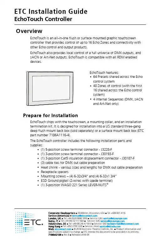
Corporate Headquarters n Middleton,Wisconsin,USA n Tel +6088314116Service (Americas)n **********************London,UK n Tel +44(0)2088961000n Service:(UK)*********************Rome,IT n Tel +39(06)32111683n Service:(UK)*********************Holzkirchen,DE n Tel +49(8024)4700-0n Service:(DE)****************************Hong Kong n Tel +852********n Service:(Asia)*******************Web: n ©2018Electronic Theatre Controls,Inc.n Product information and OverviewEchoTouch is an all-in-one flush or surface mounted graphic touchscreen controller that provides control of up to 16Echo Zones and connectivity with other Echo control and output products.EchoTouch also provides local control of a full universe of DMX outputs,and sACN or Art-Net outputs.EchoTouch is compatible with all RDM enableddevices.EchoTouch features:•64Presets shared across the Echocontrol system•40Zones of control (with the first16shared across the Echo controlsystem)•4internal Sequences (DMX,sACNand Art-Net only)Prepare for InstallationEchoTouch ships with the touchscreen,a mounting collar,and an installation termination kit.It is designed for installation into a US standard three-gang deep flush mount back box (sold separately)or a surface mount back box (ETC part number 7186A1116-4).The EchoTouch controller includes the following installation parts and supplies:•(1)5-position screw terminal connector -J3228-F•(1)3-position screw terminal connector -J30193-F•(1)3-position Cat5insulation displacement connector -J30187-F •(3)cable ties for DMX out cable preparation•Heat shrink -various sizes and lengths for DMX out cable preparation •Receptacle spacers•Mounting screws –(4)6-32x3/4”and (4)6-32x13/4”•ESD Ground pigtail (2-wires with spade terminal)•(1)3-position WAGO 221Series LEVER-NUTS ®SpecificationsAmbient EnvironmentFor indoor use only.•32°F to104°F(0°C to40°C)operating temperatures in0–95%non-condensing humidity.Compliance•UL and cUL listed•Conforms to EN62368-1(Part1Safety Requirements)•CE listed•FCC compliantElectrical and Auxiliary Wiring Specification•EchoTouch is powered by either Auxiliary power or by Power overEthernet(PoE802.3af).-Auxiliary Power-24VDC auxiliary power requires two16AWG(1.5mm2)wires and terminates to the provided removable pluggableconnector.The unit draws400mA(typical)during normal operation,with a maximum of750mA draw.-Power over Ethernet-PoE requires Category5cable or approvedequal with an RJ45(Category5compliant)connector.EchoTouchincludes an RJ45receptacle on the back panel for connection of PoE.As required,separately order an Ethernet Cat5Termination Kit fromETC(order part number4101A2003)which includes building wiretermination supplies,instructions,and an Ethernet patch cable.•EchoTouch requires an ESD Ground wire regardless of installation ofgrounded metal conduit.-ESD Ground-requires one14AWG(2.5mm2)building wire andutilizes the provided ESD ground wire pigtail and3-position WAGO221Series LEVER-NUTS®provided in the installation termination kit.Control Wiring SpecificationEchoTouch can be used with the Echo control system using EchoConnect,and provides512channels of DMX out,and512channels of sACN out to a networked system.ConfigurationThis document guides you through the installation of the EchoTouch controller.For more detailed information about graphic configuration options available,reference the integrated help system.InstallationInstall the Mounting CollarEchoTouch installs to a 3-gang deep back box,to the EchoTouch surface mount back box,or to an EchoTouch Rack-mount kit.•Listed 3-gang deep back box (by others)-in accordance with NEC and local electrical codes.•EchoTouch Surface-mount back box available from ETC (order part number 7186A1116-4).If using a surface-mount back box by others,it must be in accordance with NEC and local electrical codes.•EchoTouch Rack-mount kit available from ETC (order part number 7186A1117).Reference the Rack-mount kit installation instructions before proceeding with theinstallation.Flush mountSurface mount1.Install the back box.•Flush-mount back box-when preparing the installation location,carefully cut the hole in the wall surface material and ensurethere are no gaps around the box.•Surface mount back box-installation hardware is not provided.The installation location must support up to5lbs.(2.3kg),whichincludes the EchoTouch,surface mount back box,and wiring.Align the surface mount back box to the installation location andsecure in place using four1/4”(6mm)mounting bolts or screws(not provided).2.Run all power and control wires to the installation location.ReferenceSpecifications on page 2and Control Wiring Specification onpage 3for details.3.Install the mounting collar to the back box.a.Align the mounting collar to the back box with the arrowsdirected up.e three mounting screws(provided)to loosely install themounting collar to the back box.Install two screws on thebottom and one screw installed on the center top mounting slot(as pictured on the previous page)for optimal levelingadjustment.c.Adjust the mounting collar in the slotted mounting holes for aflush and level installation,then tighten the mounting screws.ESD Ground TerminationInstall ESD Ground Wire Pigtail1.Locate the ESD ground pigtail(2green/yellow wires with spadeterminal)in the termination kit.This pigtail will be installed on thebottom left side,between the mounting screw and the mountingcollar on the touchscreen side(as shown above).a.Loosen the bottom left screw on the mounting collar and insertthe spade terminal.b.Re-tighten the screw for a secure fit.c.Gently bend the ESD ground wire spade terminal so the wiresare directed toward the back box.2.Locate the5-position screw terminal connector in the termination kit.3.Strip1/4”(6mm)of insulation from the end of one ESD ground wireand insert it into the terminal labeled“Echo",and secure.ESD Without Grounded Metal Conduit1.Pull an additional ESD ground wire(typically green/yellow)to theinstalled back box.2.Strip1/4”(6mm)of insulation from the end of the incoming wire andthe remaining ESD ground wire from the pigtail.3.Locate the3-position WAGO in the termination kit.4.Insert the incoming wire one terminal and the remaining ESD groundwire pigtail into another terminal,closing the terminal levers ontoeach e the third terminal in the WAGO to continue the groundwire run as needed.ESD With Grounded Metal Conduit1.Strip3/8”(1cm)of insulation from the end of the remaining ESDground wire from the pigtail.2.Terminate ground wire pigtail to a ground screw inside the groundedback box.EchoConnect TerminationThis instruction assumes preparation of Belden 8471(or equivalent)cable terminating to the 5-position screw terminal connector provided in the termination kit.1.Pull all required wiring (data+,data-)into the back box.2.Strip 1/4”(6mm)of insulation from the ends of each wire.3.Terminate EchoConnect wires to the 5-position screw terminal connector provided.EchoConnect is topology free,you may install the wires in any combination of bus,star,loop,or home-run.a.Insert the data -(typically black)wire into the terminal labeled “Echo -”and secure.b.Insert the data +(typically white)wire into theterminal labeled “Echo +”and secure.24VDC Auxiliary Power TerminationEchoTouch requires external power,provided by either a24VDC(Class2)auxiliary power supply or Power over Ethernet(PoE IEEE802.3af).Terminate24VDC auxiliary power to the5-position screw terminal connector provided in the termination kit.1.Pull all required wiring(typically a16AWG black and redwire pair)into the back box.2.Strip1/4”(6mm)of insulation from the end of each wire.3.Terminate24VDC wires to the5-position screw terminalconnector provided.a.Insert the negative voltage wire(black wire typical)into the terminal labeled“24V-”and secure.b.Insert the positive voltage wire(red wire typical)into theterminal labeled“24V+”and secure.DMX Cable Preparation and TerminationThis instruction assumes preparation of Belden 9729(or equivalent)cable for termination to the 3-position screw terminal connector provided.1.Cut cable so that an 8”(20cm)tail extends from the edge of the installed back box.2.Strip 7”(18cm)off the outer jacket.3.Label the cable with the data type and run designation.(DMX1,DMX2,etc.)4.Strip the foil shielding from each wire set to within 1/4”(6mm)of the outer jacket.5.Untwist the shield wire from each pair andapply a piece of 1/16”(1.6mm)clear heatshrink to each shield wire.6.Twist each shield wire back onto its data pair,and then apply a 1.5”(4cm)piece of3/16”(0.5cm)heat shrink all the way downeach 3-wire set.Make sure to capture the foilshielding at the base.7.Apply the 2”(5cm)piece of the 3/8”(1cm)heat shrink,centered on the end of the cable jacket and the bases of all the wiresin the cable.8.Cap the ends of the unused pair of wireswith a 1”(2.5cm)piece of 3/16”(0.5cm)heat shrink centered over the end of thewires.9.Strip 1/4”(6mm)of insulation from all of the wires to be used.10.Maintain the wire pair twist as close to the screw terminal connector as possible and terminate the wires.a.(shield)wire into the terminal labeled secure.b.Insert the data -wire (typically black)into the terminal labeled “DMX -”and secure.c.Insert the data +wire (typically red or white)into the terminal labeled “DMX +”and secure.11.Bend back the unused set of wires and secure them to the cable with a wire tie.12.Secure the terminated wire sets together with a wire tie 2”(5cm)from the connector.DMX Cat5Cable Preparation and Termination This instruction assumes use of Cat5(or equivalent)cable for termination to the 3-position Cat5insulation displacement connector provided in the termination kit.1.Follow normal Cat5wire installation procedures to remove 2”(50mm)from the end of the cable jacket.2.Separate the White/Brown,Orange,and White/Orange conductors from the cable.These conductors are required for DMX out.3.Cut the remaining unused conductors from the cable flush to the cable jacket.bel the cable with the data type and run designation (for example D1for DMX run 1).5.Twist the White/Orange and Orange conductors as close to the 3-position IDC as possible and insert the conductors through the labeled terminals as follows:•Common (White/Brown)to terminal 1•Data -(Orange)to terminal 2•Data +(White/Orange)to terminal 36.Fully depress each terminal,closing it onto the wire.7.Use side-cutters to trim the excess wire from the connector.Install Touchscreen 1.Align but do not install the touchscreen to the mounting collar.Ensure the touchscreen is oriented with the label text and molded rear panel arrow directedup.tabs (x4)PoE, sACN, Art-NetStatus2.Install the prepared 5-position screw terminal connector (24VDC,ESD Ground,and EchoConnect control wires)and the utilized 3-position connector (DMX)to the designated receptacle(s)on the rear panel ofthe unit.This instruction assumes you have prepared the cables andterminated them according to the provided instructions for yourinstallation type.3.If using Power over Ethernet to power the EchoTouch,install theEthernet cable to the receptacle on the rear panel of the unit.4.Press the touchscreen into the mounting collar until the screen is flush.You will hear an audible click when the mounting tabs have fullyseated into position.5.Apply power to the unit.After boot up,press the{?}button located atthe top left of the display to access the EchoTouch online help systemwhich provides information to setup and configure your touchscreen. Release EchoTouch from the Mounting Collar Access to the back of the touchscreen is required for the following operations:•to access the provided USB port for firmware update(see UpdateFirmware on the next page)•to download a configuration file(see online help system)•to troubleshoot control wiringThis procedure requires a flat blade jewelers screwdriver(not provided).1.Gently press the tip of a jewelers screwdriver up into the provided sloton either side of the mounting collar to release the touchscreenmounting clips.You will hear and feel an audible click when the clip isreleased,and the bottom of the EchoTouch touchscreen will be free ofthe collar.2.Repeat for the opposite side of the touchscreen.3.Carefully pull on each vertical edge of the touchscreen to remove itfrom the collar.Update Firmware1.Copy the firmware update file on the root directory of a USB drive thathas been formatted to FAT32.The file will be named similarly to ETC_CS_Console_#.#.#.#.fw,where#will be replaced with the versionnumbers.2.The EchoTouch should remain powered,but carefullyremoved from the mounting collar to gain access tothe rear panel.Reference Release EchoTouch fromthe Mounting Collar on the previous page forinstructions.3.Insert the USB drive into the EchoTouch USBreceptacle located on the underside of the rear panel.4.Access the front of the touchscreen and navigate toSetup>Files>Advanced>Update Firmware.A confirmation message will display.Select“Yes”tocontinue with the update5.When the touchscreen has booted,navigate to the General tab inSettings to verify the updated software version number is displayed.6.Disconnect the USB drive from the rear panel of the unit.7.Check that all connectors and cables are fully seated then reinstall thetouchscreen into the mounting collar.。
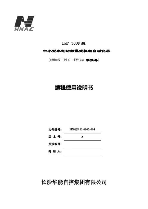
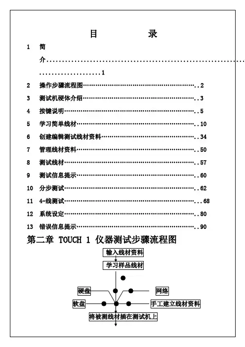
触摸屏)编程使用说明书文件编号:HN/QF.13-0002-004版本号: A发放编号:持册人:长沙华能自控集团有限公司目录1.OMRON CJ1M系列PLC介绍 (2)1.1.CPU单元(使用CJ1M-CPU13) (3)1.2.通信单元(使用CJ1W-SCU41) (8)1.3.I/O单元 (8)1.4.模块安装及地址分配 (8)2.OMRON PLC常用编程指令 (9)2.1. 梯形图指令 (9)2.2. 位元(B IT)控制指令 (9)2.3. 结束指令(END) (10)2.4. 定时器和计数器指令 (10)2.5. 数据移位元元元指令 (10)2.6. 数据传送指令 (11)2.7. 数据比较指令 (12)2.8. 数据转换指令 (13)2.9. BCD码运算指令 (14)2.10. 二进制元运算指令 (16)2.11. 逻辑指令 (17)2.12. 子程序和中断控制指令 (18)2.13. 串行通信指令(PMCR) (19)3.OMRON PLC程序编辑软件 (19)3.1. CX-P ROGRAMMER中对PLC初始化设置 (19)3.2. PLC设定 (20)3.3. CX-P ROGRAMMER中对PLC联机操作 (21)3.4. 程序中各个子程序用途定义 (21)4.OMRON PLC通信程序编辑软件 (22)4.1. 与PLC通信单元箱地址设定 (22)4.2. 4-2PLC协议编制软件(CX-P ROTOCOL)通信口设定 (22)4.3. PLC协议编制软件使用简单说明 (23)4.4. PLC与单元箱通信协议注意事项: (23)5.EASYVIEW触摸屏程序编辑软件 (23)5.1. 与OMRON PLC连接参数设定 (23)5.2. 一般参数设定(通过“编辑――系统参数一般页进行设定) (23)5.3. 组件功能说明 (24)5.4. 触摸屏程序下载 (27)5.5. 触摸屏程序调试 (27)6.水机屏PLC程序资料寄存器分配 (28)6.1. PLC内部时钟存放区(D0~D6) (28)6.2. PLC事故资料中转区(D10~D19) (28)6.3. 发生水机操作、故障、事故报警个数存放区(D20): (28)6.4. 水机状态(遥信量)存放区(D21~D30): (28)6.5. PLC事故存放区:(D4000~D5999)共存放200条事故资料 (29)6.6. PLC与单元箱通信辅助中间寄存器: (29)6.7. PLC与单元通信中断判断辅助寄存器: (29)6.8. PLC与HMI(触摸屏)间固定使用寄存器: (29)6.9. 触摸屏及后台操作定义(无特殊要求) (31)7.触摸屏模拟量显示设定 (31)8.OMRON PLC通信协议 (33)8.1. PLC使用 (33)8.2. 对时使用 (34)8.3. 单元箱使用 (34)8.4. PLC通信协议接线图 (37)1.OMRON CJ1M系列PLC介绍当前水机自动化屏大多使用OMRON CJ1M系列PLC,这种PLC为模块式,而且没有底板。

Smarter HandleUSER GUIDET H E E O W N E RHere if you need usY our ERA product is designed to be up and running in minutes, but if you do need help there are lots of handyvideos and information available on our website. Or contact us for further assistance or support.Visit or call us***********Welcome to ERA Smart Home , a complete ecosystem for home security. Visit to find out how to combine T ouchKey with the ERA Smart Home series of home security devices. Including a smart alarm system, videodoorbell, and indoor and outdoor cameras.ContentsInserting the batteries in your new TouchKeyFactory re-set the device (required for a new lock or new owner)Create account and add TouchKeyAdd TouchKey to an existing ERA Smart Home account Adding a fingerprintUnlocking the fingerprint sensor (if required)Unlocking TouchKey using the Smart Home App Auto unlock TouchKey with Geolocation via Bluetooth Setting up voice controlAccount access and user permissions Adding a Guest/Family UserFirst login and change of password for Guest/ Family User To decommission a device Deleting an ERA account Understanding your TouchKey Warranty InformationImportant things to remember12345-6789101112131415151617Replace battery cover.Remove battery cover by slidingit away from the hinges.Insert 4 x New CR123A batteries and the LED will flash RED and then start flashing BLUE signifying that your TouchKey is ready to pair.*Depending on the orientation of your door, you may have a left or right handle installed. The orientation of the batteries within the battery compartment will di er for each.Please ensure you check that the battery is fitted the correct way (see diagram within compartment).Inserting Batteries1. 2.3.Factory Re-set the deviceRequired for a new lock or a new ownerAn LED light on the external handle will start flashing BLUE after reboot, to confirm the product has been reset.There is a small pinhole reset button on the side of the internal handle, just above the handle grip.Using a pin or the point of a paperclip, place into the hole and press for at least 5 seconds.Release pin, and your T ouchKey will flash RED and then reboot.4.1. 2.3.Download the ERA Smart Home App (iOS or Android). T urn on your Bluetooth.Create account and add TouchKeyOpen the App and create an account by completing required details.A verification code will be sent to your registered e-mail account. Enter the code into the App when prompted.1. 2. 3.XXXXFollow steps 7 -9 from the previous page.Adding TouchKey to an existingERA Smart Home accountT urn on Bluetooth in your phone settings.1.2.4.5.6.theAdding a fingerprintT GREEN LED fingerprint (finger/thumb), place this over the black sensor on the front of the external handle.The GREEN LED on the external handle will stay illuminated for 2-3seconds while the sensor reads the fingerprint.The fingerprint icon will update once successful.1. 3.7.8.Adding a fingerprint (continued) Follow the on screenApp instructions, hold your finger centrally as you move through the 3 fingerprint screens.Once completed, yourfingerprint should havebeen successfully addedto the T ouchKey.If you experience anyissues adding a fingerprintthe App will return to thestart, where you canrepeat the process.T o add additionalfingerprints and usersrepeat the above steps.9.10.11.15.16.T o enhance any enrolledfingerprint, click on thethree dots next to analready enrolled fingerprint.From the sub menu, select"Enhanced FingerprintSetup" and follow the onscreen instructions.Unlocking the fingerprint sensorIf there are 12 consecutive failed fingerprint attempts by a user or users, to open the door, then the fingerprint sensor will be disabled.Once disabled, the fingerprint sensor on the handle will remain unresponsive to touch until unlocked.T o unlock it, you need to verify (with two-factor authentication) that an authorised user is trying to unlock the door.Standing near the door, open the Smart Home app and go the to T ouchKey dashboard.Y ou will see a message in the T ouchKey dashboard that the fingerprint sensor is disabled.When prompted, press and hold the fingerprint on the app screen for a few seconds.The app screen will switch from red to green as the fingerprint is verified and finally to the T ouchKey screen, once authorised.The fingerprint sensor is now unlocked and ready to use.1.2.3.4.5.Unlocking the TouchKey by using the AppOpen the ERA Smart Home App (iOS or Android).Ensure you are standing less than 2m from the T ouchKey handle and that Bluetooth is enabled on yourmobile device. Select "TouchKey"from the menu.Press the centre of the circle containing the "padlock", to unlock T ouchKey.A GREEN LED light will display onthe external handle. Y ou will hear the door unlock, please then push the handle down.4.1. 2.3.2mAutomatically unlocking TouchKey with Geolocation via BluetoothOpen the ERA Smart Home App (iOS or Android) and select T ouchKey.Open the T ouchKey settings for your device. and choose the “Geolocation Lock Control” option from the menu. When activating Geolocation, stand close to the door for precise recording of location coordinates.When you activate this feature, it allows you to automatically unlock your door when you return home from beyond the 200 metre distance range. The lock will then only physically open when you are 5-10 metres from your T ouchKey.The feature is based on the location of your registered smartphone, which will require permission to use your phone location in the App settings. Please ensure that you change location access in your ERA Smart Home App to “Always” (without setting, geolocation will not function).Y ou must leave your App running in the background on your phone forgeolocation to initiate. If you close the App you will get a notification (iOS only) that services to the handle have stopped and request you reopen the App to restart services to the handle.Y ou must move outside the 200 metre range from your lock to initiate the feature.When you return inside the 200 metre range, the lock will prepare itself for your arrival, but will not unlock until your phone is 5-10 metres from the T ouchKey. This is for security reasons.As you walk up to your door, T ouchKey will fully open once you are 5-10 metres away*. Y ou can gain access to your property by using the handle.*time span can be adjusted within the App1.2.3.4.5.6.7.8.Setting up voice controlY ou can now openTouchKey by using thefollowing phrase “Hey Siri,unlock ERA TouchKey”.Please note, that you canpersonalise the phrase ifyou wish within the setup process. For examplechanging to “Hey Siri,unlock my door”.Voice unlock1. 2. 3.4. 5.TYclickon-screen Siri promptsto finalise set up.Account Access and User PermissionsCreating a Guest/ Family User10 Accounts maximumOpen the ERA Smart Home App (iOS or Android).Open “Account Settings” in the ERA Smart Home Menu.In the “User Detail” section, select “Guest User” (you will see any guests already set up in case you wish to edit).Click on “ + ” and select the type of account you wish to add.Select the type of user you wish to create - Guest or Family. Complete their details including their email and phone number.In the share section at the bottom, you can choose the functions you wish to share by selecting/ deselecting the options.Once you have set up any specified dates/ times/ access levels etc. click “Save” Y ou will then receive a notification that the Guest Invitation has been sent.The Guest user you have created will be added to the Guest User List in your App.1.2.3.4.5.6.7.8.Guest/ Family UserFirst login and change of passwordsystem sends an email once the administrator created“you” as a Guest User). Thenenter a brand new password, confirm this password and then click “Save”.Download the ERA Smart Home App (iOS or Android).1.Open the App on yourmobile device and create an account by completing 2.T Service and Privacy Policy.3.4.5.6..To decommission a deviceHow to delete Fingerprint:Open the ERA Smart Home App.Select T ouchKey.Select "TouchKey Settings" (accessed by the menu or the settings icon on the T ouchKey dashboard in the top right hand corner, once the T ouchKey has been connected).T o decommission a device please delete all fingerprints (you need to be within 2m of the handle to perform this action).Go to the bottom of the T ouchKey Settings page:Y ou will see the Delete T ouchKey icon Now click 'Delete T ouchKey'.Please 'FACTORY RESET' your T ouchKey lock to restore the lock to the factory settings. See page 2.Go to Fingerprint settings in the T ouchKey Settings page Click on the Fingerprint you want to delete Y ou will see Delete/Edit Click on DeleteFingerprint will be deleted.1.2.3.4.5.6.1.2.3.4.5.1.2.Deleting an ERA accountEnsure that all devices associated with your account have been deleted.Send an email to customer support at ************************from the primary email address associated with your account informing them you wish to delete your account.ERA will respond to your request within 14 days. This may be extended further, if additional information is required.ERA will confirm by email that the account has been deleted.1.2.3.4.Understanding your TouchKeyLED ColourDefinitionWarranty InformationOur PromiseWe at ERA firmly believe in the quality of our goods. Our technology achieves outstanding performance and durability and we can therefore o er, in addition to your statutory rights, an additional limited guarantee.Hardware: a 10 year guarantee commencing on completion of installation.Smart Security: a 2 year guarantee commencing on completion of installation.Critical Security and Firmware Updates: for 4 years from the major version date of the software within the ERA T ouchKey.If a material defect occurs in the hardware or smart security before the end of the relevant guarantee period set out above, ERA will (in its sole discretion) replace the hardware or security (or the defective part thereof) free of charge.ERA may, as part of any replacement of hardware or smart security, supply alternative hardware or smart security that it considers to be of similar or better quality where the particular hardware or smart security subject to the defect are obsolete or otherwise unavailable.The ERA T ouchKey Guarantee is only valid when the following terms and conditions are met in full:This limited guarantee is not transferable and is extended only to, and is solely to the benefit of, the original purchaser of the product. Please retain your dated sales invoice as proof of purchase and forward this to us if you wish to make a claim under this guarantee.Products must be installed, used and maintained in accordance with our instructions otherwise the guarantee will be invalidated. The product must not be damaged or modified in any way nor must it have been subjected to any unauthorised repairs.ExclusionsT o read the guarantee terms and conditions, including exclusions in full, please visit . The ERA T ouchKey Guarantee is in addition to your legal rights. It does not exclude, restrict or modify your legal rights, including under consumer law in the UK.To make a claimY ou must first notify your installer using the details they will have provided you. If your installer is not providing you with the assistance you require, you can phone us at 0345 646 1487 (during o ce hours) and we will then provide you with assistance in making your claim under the ERA T ouchKey Guarantee.*T erms and conditions apply.Recycling and disposalDisposal of this product is covered by the Waste Electrical or Electronic Equipment (WEEE) Directive. It should not be disposed of with other household or commercial waste. At the end of the product's useful life, the packaging and product should be disposed of via a suitable recycling centre.EC Declaration of ConformityERA hereby declare that this equipment complies with the essential requirements of the Radio and T elecommunications T erminal Equipment Directive 2014/53/EU. A copy of the EU Declaration of Conformity is available at .All rights reserved. All trade names are registered trademarks of respective manufacturers listed. App Store is a service mark of Apple Inc. Android and the “Google Play” logo are trademarks of Google Inc. Phone not included.Data ProtectionERA is committed to processing your personal data in compliance with all applicable data protection laws. For more information regarding how we process your personal data, please see our privacy policy at or it is available from us on request.ERA Home Security LtdValiant Way, Wolverhampton,West Midlands, WV9 5GBCustomerHelpline************。
用户手册Elo Touch Solutions 1509L Touchmonitors版權所有© 2021 Elo Touch Solutions, Inc. 保留所有權利。
未經Elo Touch Solutions Inc. 的書面許可,不得以任何形式或方法(包括但不限於電子、磁性、光學、化學方法或手冊等)複製、傳輸或改編本出版物的任何部分,不得將其儲存到擷取系統,不得將其翻譯成任何語言或電腦語言。
免責聲明本文件中的資訊有可能在未通知的情況下進行變更。
Elo Touch Solutions, Inc. 及其附屬公司(共同稱為「Elo」)對本出版物的內容不提供任何形式的陳述或擔保,並且特別聲明拒絕對有特定目的適銷性或適用性提供任何默示擔保。
Elo 保留對本出版物進行修訂並對其內容不斷進行變更,而不將這樣的修訂和變更通知任何人的權利。
商標確認AccuTouch、CarrollTouch、Elo、Elo(標誌)、Elo Touch、Elo Touch Solutions、IntelliTouch、iTouch、SecureTouch、TouchTools 和VuPoint 是Elo 及其附屬公司的商標。
Windows 為Microsoft Corporation 的商標。
目录第 1 章- 简介 (4)第 2 章- 安装 (5)第 3 章- 安装 (11)第 4 章- 操作 (12)第 5 章- 技术支持 (15)第 6 章- 安全与维护 (16)第7 章- 法规信息 (17)第8 章- 担保信息 (20)第 1 章- 简介产品说明新的触摸显示器集Elo Touch Solutions触摸产品的可靠性能和触摸技术与显示屏设计领域的最新进展于一身。
这种性能组合可在用户与触摸显示屏之间提供自然的信息流动。
此宽屏触摸显示器带有一个24 位彩色有源矩阵薄膜晶体管LCD 面板,提供了优异的显示性能。
其LED 背光可极大降低功耗并消除汞的使用(相比于CCFL 背光面板)。
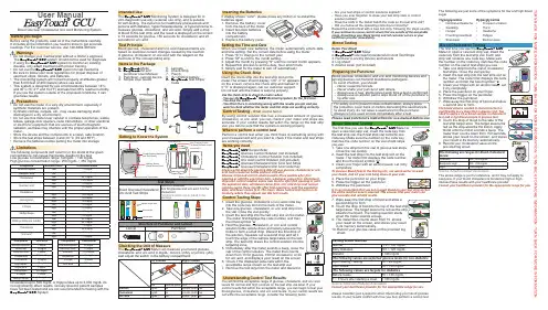
It includes all the information you need to know to get accurate readings. For EU customer service, dial +49-6894-581020.Warnings• Do not change your medical plan without a doctor’s approval. The EasyTouch ® GCU system should not be used for diagnosis.• If using the EasyTouch ® GCU system to monitor an existing disease, only adapt treatment with proper training.• Do not use the EasyTouch ® GCU system to test newborns.• Be sure to follow your local regulations for proper disposal of used test strips, lancets, and batteries.• The monitoring system will not work properly at altitudes greater than 8,000 feet (2,400 meters) above sea level.• This system is designed for use at temperatures between 14°C and 40°C (57.2°F and 104°F) and less than 85% relative humidity. If you use the system outside of the proposed conditions, it can give false results.Precautions• Do not use the meter in a very dry environment, especially if synthetic materials are present.• Synthetic clothes, carpets, etc., may cause damaging static discharges in a dry environment.• Do not use this meter near cellular or cordless telephones, walkie talkies, garage door openers, radio transmitters, or other electrical or electronic equipment that are sources of electromagneticradiation, as these may interfere with the proper operation of the LimitationsTh e following compounds (left column) in the blood at the given concentrations can cause inaccurate results on the test.Low glucose concentration range: 50mg/dL ~ 100 mg/dL User ManualBlood Glucose/ Cholesterol/ Uric Acid Monitoring System- You think there is something wrong with the results you got and you want to check whether the meter and test strips are working correctly.By using control solution that has a measured amount of glucose, cholesterol, or uric acid, you can check if your meter and strips are accurate. If your control results fall within the range on the test strip vial, you can be sure that the system is working properly.Perform a control test when you think there is something wrong with your measurement and you want to check if the meter and test strips are working correctly.EasyTouch ® GCU Series MeterEasyTouch ® Glucose Control Solution (not included)EasyTouch ® Cholesterol Control Solution (not included)EasyTouch ® Uric Acid Control Solution (not included)EasyTouch ® Glucose/Cholesterol/Uric Acid Test Strips EasyTouch ® Glucose/Cholesterol/Uric Acid Code KeyAlways write down the opening date of your glucose, cholesterol or uric acid control solution bottle and test strip vial.Glucose strips and control solution expire three months after firstopening or until the expiration date, whichever comes first. Cholesterol strips and control solution expire two months after first opening or until the expiration date, whichever comes first. Uric acid strips and control solution expire three months after first opening or until the expiration date, whichever comes first. The meter stores control test results in its levels for normal and high controls on the test strip vial label. If yourcontrol results fall within the acceptable range, you can begin to test your blood glucose, cholesterol, and uric acid levels. If your control results are not within the acceptable range, consider the following items:Getting to Know the SystemControl Testing - What control test isWhen to perform a control testItems you needand time setting. Set the correct date before using the meter.1. Press "S" to change to the current year.2. Press "M" to shift to the month setting.3. Adjust the month by pressing "S" until the current month appears.4. Repeat this process to set the date, hour and minute. Items in the PackageScreen(Display Messages 1. EasyTouch Meter 2. EasyTouch Kit andpuncturer User Manual 3. Puncturer - lancing device 4. Simple User Guide5. Lancets6. Check Strip7. Pouch8. 3V CR2032 battery 9.EasyTouch Test Strips/ Code6GCUInserting the BatteriesIf display shows "conn", please press any botton or re-install the Intended UseThe EasyTouch ® GCU Monitoring System is designed for in vitro diagnostic use only (external use only), and is suitable for self-testing. The system is for healthcare professionals and persons with diabetes, hypercholesterolemia, or hyperuricemia to measure glucose, cholesterol, and uric acid. Simply add a drop of blood to the test strip, and the result is displayed on the screen in 10 seconds for glucose, 150 seconds for cholesterol, and 20 seconds for uric acid. Test PrincipleBlood glucose, cholesterol and uric acid measurements are based on electrical current changes caused by the reaction of glucose, cholesterol, or uric acid with the reagent on the electrode of the corresponding strip.glucose, 50 most recent cholesterol, and 50 most recent uric acid testresults. You can review the test results in order from the newest to theoldest. If the memory is full, the oldest result is deleted as the newestresult is added. The memory is not affected by replacing or removingthe batteries.• Do not submit your meter to strong impact or pressure.• Keep your meter between -10°C and 60°C (14°F and 140°F)and less than 95% relative humidity. Do not store the meter inareas such as the kitchen, bathroom, laundry room, or car.• Keep the meter away from water.• Do not use glass/household-cleaning solutions to clean themeter. Simply use an alcohol pad to wipe the surface of themeter, but do not wipe the test strip slot or code key slot.• Do not disassemble the meter.• If you have any questions, please contact customer serviceClean the meter with a 70% isopropyl alcohol swab.• DO NOT spray any cleaning solution directly onto the meter.• DO NOT dampen the code key slot or the test strip slot.1. Slide battery cover off the back of the meter.• Remove the old batteries and insert 2 new AAA size batteries(1.5V) into the battery compartment.2. Slide battery cover back in place and turn on your meter.Maintenance - Taking Care of Your MeterCleaning the Meter* The Meter has been safety and EMC tested and approved according to therequirements of EN 61010-1/EN 61010-2-101/EN 60601-1-2/EN 61326-1/EN61326-2-6, and EN60601-1.The following are ranges for uric acid levels:Male 3.5 ~ 7.7 mg/dL (309 ~ 680.68 μmol/L)Female 2 ~ 6 mg/dL (176.58 ~ 530.4 μmol/L)The above range is just for reference, and it may not apply to everyone.If your blood uric acid is high, discuss these results with your healthcareprovider.Consult your healthcare provider for the appropriate range for you.of “M”. The meter will turn off automatically in 3seconds when the symbol “----” is displayed on thescreen.succession to confirm that the result has been deleted.4. The meter then displays the next-most-recent result.。
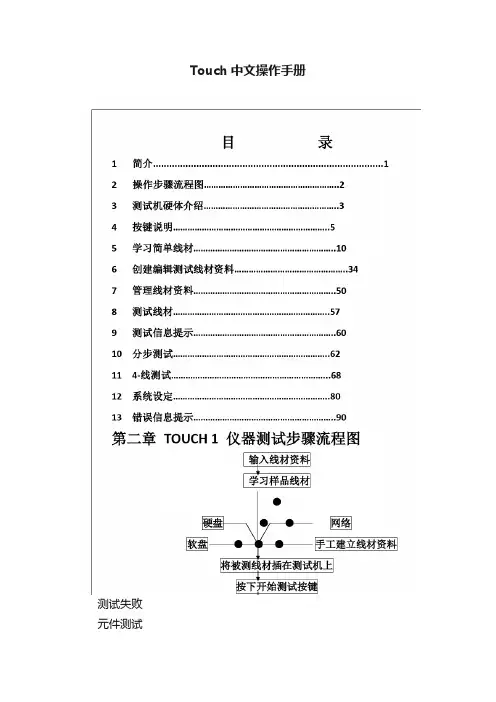
Touch中文操作手册测试失败元件测试失败(元件错误)高压测试失败(高压错误)瞬间断电测试时好时坏好线材移开产品,准备下一个测试第三章测试机硬体介绍1.110V/230V 电源开关1500VDC 1000VAC2.如何安装治具板A.打开卡锁,取下盖子卡锁关闭状态卡锁打开状态B.插入治具板,再将盖子盖上3.接口位置及名称1500 V Touch 11000V Touch 1 OK NG OK OK NG NGOK主电源开关软驱打印机接口输入输出接口第六章创建、编辑测试线材资料1:如何进入编辑画面A.Main Menu 画面,按Test SetupB.在Test Setup 画面,按View & ChangeC.编辑线材资料画面如下2:如何编辑治具板2-1如何在线材表中增加一个治具板A.在View/Change Wirelist 画面,按ADP,再按CHANGE ADPB.在Change Adapters 画面,按ADDC.在Add Adapter Position 画面,使用“▲”“▼”选择治具板位置,然后按AddD.在Add Adapter 画面,使用“▲”“▼”选择之治具板编号,再按AddE.在 Change Adapter 画面,显示新的治具板2-2 如何从线材表中删除治具板A.在View/Change Wirelist 画面,按ADP,再按CHANGE ADPB.在Change Adapters 画面,使用“▲”“▼”选择之治具板编号,再按DELETE ,然后按OK 3:编辑低压参数设定3-1编辑低压导通阻值低压导通阻值编辑范围:0.1ohm –100 K ohm (±1%±0.1ohm 1500V)(±4%±0.1ohm 1000V)500 K ohm, 1M, 5M, (±10% 1500V)(±20% 1000V)限定:当测试元件时,低压通导阻值不能大于100K ohms软驱键盘接口探针接口输入输出接口串行口打印机接口操作如下:A.在View/ Change Learn Settings 画面,触摸LV键,然后触摸CHANGE LV键,进入CHANGE LOWVOLTAGE画面:B.在CHANGE LOW VOLTAGE画面,触摸通导阻抗,进入ENTER CONNECTION RESISTANCE画面。
使用者手册2201L 觸摸顯示器版權所有© 2011 T yco Electronics。
保留所有權利。
未經 Tyco Electronics 的書面許可,不得以任何形式或方法(包括但不限於電子、磁性、光學、化學方法或手册等)複製、傳輸或改編本出版物的任何部分,不得將其儲存到擷取系統,不得將其翻譯成任何語言或電腦語言。
免責告示本文件中的訊息有可能在未通知的情况下進行變更。
Tyco Electronics 對本出版物的內容不提供任何形式的陳述或擔保,並且特別宣告拒絕對有特定目的適銷性或適用性提供任何默示擔保。
Tyco Electronics 保留對本出版物進行修訂並對其內容不斷進行變更,而不將這樣的修訂和變更通知任何人的權利。
商標告示Elo TouchSystems、IntelliTouch、iTouch、Tyco Electronics 和 TE(標誌)是 Tyco Electronics 集團公司及其許可方的商標。
Windows 為 Microsoft 集團公司的商標。
本文件中出現的其他產品名稱可能是其各自公司的商標或注册商標。
Tyco Electronics 對除自有商標以外的其他商標不享有任何權益。
目錄第 1 章 – 簡介 (4)第 2 章 – 安裝 (5)第 3 章 – 安裝 (9)第 4 章 – 操作 (10)第 5 章 – 技術支援 (14)第 6 章 – 安全與維護 (15)第 7 章 – 法規訊息 (16)第 8 章 – 擔保訊息 (19)第 1 章 – 簡介產品說明新的觸摸顯示器集 Elo TouchSystems 的可靠效能和觸摸技術與顯示屏設計領域的最新進展於一身。
這種功能組合可在使用者與觸摸顯示屏之間提供自然的訊息流動。
此觸摸顯示器帶有一個 24 位彩色有源矩陣薄膜晶體管 LCD 面板,提供了優异的顯示效能。
其全 HD 解析度 1920x1080 適合顯示圖形和影像。

Touch使用手册目录触碰传感器安装 (7)一、触碰传感器安装 (7)1.触碰传感器安装: (7)2.触碰传感器接收器: (7)2.1触碰传感器接收器图片 (7)2.2触碰传感器接收器,安装在指定位置,并且接上网络: (8)2.3系统连接方式: (8)2.4商场店面布局: (8)3.触碰传感器接收器配置 (8)3.7进入网络---接口: (10)3.8修改WAN接口: (10)3.9获取设备MAC地址 (12)4.配置完成,连接设备 (12)二、单间测试办法: (12)TouchAPP使用说明 (14)一、登录页 (14)1.输入服务器名、用户名、密码,点击登录,跳转店铺首页 (14)二、店铺首页 (15)3.店铺列表,根据店铺名称首字母分类呈现 (15)三、店铺详情页 (16)4.列表说明 (16)5.点击设备列表,进入设备详情页 (16)四、绑定添加界面 (16)五、扫一扫界面 (17)1.把二维码或者条形码放入框中,自动扫描,晚上操作可打开手电筒 (17)六、设备详情页 (18)1.点击1处,可进行手动编辑, (18)2.点击2处,可跳转扫描页,扫描编号 (18)3.修改后,点击保存即可 (18)TouchPC端使用说明 (19)一、登录网址: (19)二、店铺管理: (19)1.店铺维护: (19)1.1店铺管理---店铺维护; (19)1.2增加店铺: (20)1.3查询店铺: (20)1.4修改店铺: (21)1.5删除店铺: (21)1.6营业时间维护: (22)2.1店铺管理---店铺种类管理 (24)2.2选择查询店铺---查询; (25)2.3增加店铺种类: (25)2.4修改店铺种类: (25)2.5删除店铺种类: (26)3.1查询:选择店铺---查询; (26)3.2增加接收器: (27)3.3修改接收器: (27)3.4删除接收器: (27)4.1增加货架: (28)4.2修改: (29)4.3删除: (29)三、客流报表: (30)1.触碰数据查询: (30)四、系统设置: (30)1.用户组维护; (30)2.部门维护; (32)3.角色维护: (34)4.账户维护: (36)5.人员角色维护: (37)6.人员部门维护: (38)7.人员部门维护: (39)8.系统权限维护: (39)9.类别维护: (40)10.分区维护: (41)11.城市省份维护: (42)12.品牌维护: (43)触碰传感器安装一、触碰传感器安装1.触碰传感器安装:1.1触碰传感器图片;1.2触碰系统电池安装;1.3使用内六角扳手拆开扣锁,解开外壳。
User ManualEC TS-1510 Touch Screen MonitorTable of ContentsChapter I: Overview (2)1.1 Safety Information (2)1.2 Electromagnetic Compatibility Statement: (3)Chapter II: Installation Guide (5)2.1 Appearance of EC TS-1510 Touch Screen Monitor: (5)2.2 The Rear Panel I/O Signs and Description: (5)Chapter III: Instructions for Installation (6)Chapter III: Instructions for3.1 Touch Screen Driver Installation: (6)Chapter IV: Common Faults and E E xclusion (16)Chapter IV: Common Faults andChapter I: OverviewDear value customers:Thank you for purchasing the EC LINE products; we are committed to continuously maintenance the product quality and providing better after-sales service. In order to take full advantage of our devices, we recommend read through this manual before the driver installation.1.1 Safety InformationEC TS-1510 is fully compliance with the relevant requirements of the national standard GB/4943-2001 IT equipment security.Make sure the electricity meets the power requirements (such as voltage, frequency) before installation; and the grounding of the power outlet is running properly.Lightning may damage the product, unplug the network cable, power cable or any other conductors during lightning storms.Do not unplug the components and connections (except for the USB device) when the power is on.Do not open the cabinet of the product by a non-professional technician.Do not leave any item or liquid inside the product; do not place any objects into the ventilation holes, it may cause short-circuit of the internal components and may cause fire or electric shock.In accordance with the relevant explanation in national standards GB/T9813-2000 microcomputers general specification. After the computer is below the temperature of 10 ° C of environment storage, please place the machine in room temperature (10-35 ° C) conditions for more than two hours to avoid damage from low temperature. In the meantime, please do not remove the packaging and allow the computer to restore the naturaltemperature, and avoid heating up too fast to cause the computer to generate the occurrence of frost and condensation that might bring electrical damage.Strict compliance with the electrical appliance standard;Safe use voltage range: 100V ~ 240V & 50Hz/60Hz;Verify that the power outlet is available to connect to a reliable ground;Keep the device clean, dry, away from dust, moisture and direct sunlight;Do not share the same power outlet with high-power consumption electrical devices, keep distance from high level magnetic interference;Power off the monitor after use as to extend using life;Do not use sharp points, draw, cut the touch screen to ensure the normal use of it;Switch off the power supply before plug / unplug the communication cable or connect to an external device;Non-professional and technical personnel is not allowed to open the machine, otherwise take upon the consequences;When the following occurs:Liquid penetrate into the body of the monitorMonitor accidental damageMonitor produces a burning smellMonitor shows sudden abnormalDisconnect the power supply immediately, unplug the power cord and contact a qualified service technician to do service.1.2 Electromagnetic Compatibility Statement:EC TS-1510 is fully compliance with the relevant requirements of the national standards (GB/9254-1998) “The limits and measurement methods of radio disturbance characteristics of information technology equipment” for Class Bproducts.EC TS-1510 is fully compliance with the relevant requirements of the People's Republic of China’s national standards of (GB/17625.1-2003) “Electromagnetic Compatibility Limits for harmonic current emission limits”for Class B products.Chapter II: Installation GuideChapter II: Installation Guide2.1 Appearance of EC TS-1510 Touch Screen Monitor:2.2 The Rear Panel I/O Signs and Description:A row of the external device connection interface is located at the rear bottom panel of the monitor, such as: power outlet, Line in, VGA and USB interface, detailed as follows:USB: Touch panel function interfaceLine in: For connection to the PC audio-out connector of sound source(option)VGA in: For connection with the D-Sub 15 pin signal cableDC in: For connection with the power adapterEC TS-1510 touch screen monitor is using the manual handle design which is able to be adjusted within the range of 0 degrees to 90 degrees to make the operation more humane.Chapter III: Instructions for Chapter III: Instructions for Installation Installation3.1 Touch Screen Driver Installation:Step 1: Open the installer directory in the CD, double-click “Setup.exe”Step 2: Installation started as the following figure shown, click Next to proceed thenext stepStep 3: Installation in progressStep 4: Click “install PS / 2 interface driver” and click Next to proceed installationStep 5: For the touch interface is RS232, click “install RS232 interface driver” and click Next to proceed installation.Step 6: When choosing the calibrations, select NONE, click Next to proceed installation.Step 7: When installing USB touch, please connect the USB controller and USB cableStep 8:When there are two or more touch screen, please tick “Support multi- monitor system”.Step 9: Select the destination location to store the driver, the default path is C: \ Program Files \ eGalaxtouch; we use the default path here, click Next toproceed to installation.Click Next to proceed to installationStep 10: Check the message to create a desktop shortcut icon in the following figureAfter install the driver successfully, identify the USB controller card and RS232 control card as the following two figures shows.Related touch function settingTouch calibrationTouch device line testTouch screen settingTouch device edge correction settingTouch device hardware information displayChapter IV Chapter IV: Common Faults and : Common Faults and : Common Faults and E E xclusion xclusion1. No display on the screen i)Power saving mode is on, press any key on the keyboard or move the mouse to deactivation.ii) The pins of the VGA cable connector are bent or lost contact to the VGAinterface, change the VGA cable. If problems still exists, bring the unit to the service provider.2. Characters look too dark or to light Using OSD Menu to adjust the brightness3. When your monitor needs to be adjusted? The resolution of frequency is unclear4. The text appears on the screen are unclearMake sure the resolution or refresh rate are matching with the Display Mode5. Touch panel doesn’t respondMake sure the touch screen driver is installed properly into your PC system and calibration is done.Thank you very much for using EC Line productForservice,*******************************.hk.mx / 。
Controlling ELM w/ OSC and TouchOSCCreate a convenient, user-facing control surface for your ENTTEC Pixel systems IntroductionIn this guide we are going to learn how to use the OSC protocol and 3rd party application Touch OSC to create a simple control surface for your ELM pixel system. The goal is to make a user-facing control panel that we can pass to a non-technical end user so they can control their lighting rig, without needing to have a working knowledge of the ELM software.This is a panel with 5 pre-set patterns, and a master intensity control. Using the following steps, you can create a custom control surface as simple or complex as you need.1 - Sample TouchOSC Control PanelCreating the Touch OSC layoutFor this part, you’ll need TouchOSC Editor – which is available from the Hexler website. This app lets you design your control surface on a computer, and then transfer that over to your tablet/phone.When you open the editor, you will see a blank black box representing your device screen. Begin by naming this screen and selecting the screen size.TouchOSC editor has multiple pre-set sizes applicable for Apple devices, for many smart phones the iPhone 6 plus is a close match. Alternately you can enter your own custom values to match the screen resolution of your device.3 - TouchOSC Editor Screen Size Selector4 - TouchOSC Editor Screen Size Options2 - TouchOSC EditorNext, you will need to add a fader to control intensity in ELM. To do this right click anywhere on the black space of your layout. A drop-down list will appear with of all the elements you can add. In this case select a vertical Fader (Fader V).Now you can position it where you want and scale it with the re-size markers on the corners and sides. You can also change the colour and name of your element, allowing for quick and easy identification. Be sure to check the inverted button to ensure your fader moves in the expected direction.The layout builder always shows elements with the value of 0 so if the solid bar is at the top it will need to be inverted.Once you are happy with the position, you can now configure the OSC command string. Touch OSC tries to create default strings based on the item’s name. You will need to uncheck this allowing you to enter 5- Add Element6 - Format Element7 - Element Colour Changeyour own string. Consult the ELM user manual or the convenient list in ELM under the OSC remote settings page.For Intensity you will need to enter “/elm/stages/Stage01/live/intensity”. Leave light and low values as they are.Note – the OSC string is caps sensitiveNote – Stage01 refers to the stage you want to control. If you named your stage something different then you need to use that instead. You can also use * to refer to all stages this would look like “/elm/stages/*/live/intensity”8 - Configure Command String9 - ELM OSC Command StringsNow that you have made your intensity fader, you can move on to making buttons to select the media you want to send. A push button is recommended for this. Select it from the same menu used for selecting your fader.Re-size and move it to a suitable place on your control panel.As before you now need to set the OSC command for the new button This is like setting the intensity.Enter “elm/stages/Stage01/live/media” then in the value boxes set them both to be the same. Thisbutton will be selecting media slot 1 so set both the high and low values to be 1. If the low value is left at 0 it will act as a momentary switch, only activating the media while the button is held downNext move on to the remaining 4 buttons. This can be done by repeating earlier steps, however, it is much faster to copy the button you have just made and paste it down. This also makes sure all your buttons are the same size and shape. Any copy and pasted buttons then just need their high and low valued updated to select a new piece of media so the second buttons high and low values should be set to 2, button 3 to 3 etc.Adding labels is another useful way to keep track of what each element does. These are created in the same way as all other elements. Right click on the black space and select from the drop-down menu as needed.The text and size can also be edited from the side menu just like other elements.10 - Create Push Button Element11 - Setting Command String on Media Button12 - Insert Label13 - Adjust LabelFinally tidy up your screen using the align and distribute tools. These are great for giving your space a clean, user-friendly look. Access these by selecting multiple elements, ‘drag and draw’ over the targets and then right clicking an element. You can then select the desired tools from the drop-down menu. Once you are happy with your layout, save it and then transfer it over to your phone or tablet, so we can later set this as our layout screen. We’ll also show you how to import this directly from your computer a bit later on.14 - Align ElementsConfiguring ELM for an OSC RemoteYou can now shift your attention to the ELM software to prepare it for receiving OSC commands. Open ELM and make your stage using the same name that you have specified in Touch OSC editor (remembering it is case sensitive).Then navigate to the OSC remote settings. Path – Settings>Remote>OSC. Simply turn the switch to ON to allow ELM to receive OSC commands.15 - ELM - Create Stage16 - ELM OSC TabELM-TouchOSC Remote Control – V1For the latest version visitthe ENTTEC websiteFrom here you just need note down the port that is being used. The default is 9001 but you can change it if desired. Feedback can be left off as it is not needed for this design.Note – the complete list of commands for controlling ELM is also listed here so you do not have to gosearching through the user manual.Lastly make sure your media is in the same slots used in your TouchOSC layouts buttons.That’s it, now ELM is set up ready to be able to receive OSC triggers from your phone or tablet.17 - ELM OSC Settings18 - ELM Media SlotsConnecting Your Phone/Tablet to Your ComputerTo connect your computer to your phone, install and run TouchOSC bridge – available from the Hexler website - https:///products/touchoscThis plugin runs in the background and acts as the link between your programs and the TouchOSC app. You also need to know the IP address of the computer for later steps. There are many ways to do this. Depending on how your Pixels have been connected you can get the IP address from ELM by going to your output settings and seeing the IP address of the adapter you are using to send your Art-Net.Another reliable way of getting the IP address of your computer is to open command prompt which can be done by pressing [start] and typing “command prompt”Then simply type “ipconfig/all” and press [ENTER].19 - ELM Output Settings20 - Command PromptThen scroll up till you see the adapter you are using and look for the IPv4 settings.Now we need to open and configure TouchOSC. Open the TouchOSC app on your phone/tablet. When you first open TouchOSC it will show one of the many defaults loaded layouts. To change these settings,simply press the circle in the top right corner of the screen and go to Layout to select your own.3 - IP Config Results22 - Touch OSC Default LayoutClick on the OSC tab, under Settings, from there enter the proper details into the different fields. Some devices will be recognized by the app and you can simply click on them for the app to auto fill the necessary settings. If not, enter the details manually- Host - is the IP Address of your computer, which we previously determined to be 192.168.1.20 -Port (outgoing) - needs to match the port that ELM is expecting to receive on, which as we saw before, defaulted to 9001- Port (incoming) - since our control panel is not receiving any feedback, this setting is irrelevant -ZeroConf Name - you can change this to give your device a unique name23 - ELM OSC Port Setting24 - OSC App SettingsNext the TouchOSC Bridge settings need to be configured. Enter the IP address of the computer inTouchOSC Bridge. As with the OSC tab this will auto discover some computers but if it does not then just enter the IP manually.Once those settings are configured, go back to your computer and TouchOSC editor. Click the sync button and wait for the pop up to appear.Now that the editor is ready to synchronise, switch back to your device running the TouchOSC app, enter the layout menu and select “Add from Editor.” Enter the IP address of the computer running the editor and press download. You can then scroll down the list to find the layout you imported and select it but tapping on it so that it is checked. This is another way to import your layout onto your phone/tablet,besides to just transfer the file across manually.4 - TouchOSC Bridge Setting26 - TouchOSC Bridge Setting27 - TouchOSC Bridge SettingHead back out of the settings on your phone/tablet by using the back arrow and pressing “Done.” You should be able to see and use your layout. You can now freely move the fader, press the buttons, and have ELM respond and reflect your changes on its live tab. You can also check if ELM is receiving OSC by looking to see if the box has gone green in the OSC remote tab.5 - Download LayoutELM-TouchOSC Remote Control – V1For the latest version visitthe ENTTEC website That brings us to the end of this guide, by the end, you’ll have a control panel on your phone or tablet to give you or your client a simple, yet professional control surface for manual control over their pixel mapped setup. And this is just the beginning. With a bit of time and ingenuity you can create even more sophisticated control panels.Check out these sleek control surface examples from the Hexler website:29 – TouchOSC Examples。
ECTouch 帮助中心1. 使用手册 (2)1.1商店设置 (2)1.1.1网店设置如图1 (2)1.1.2基本设置如图2 (2)1.1.3显示设置如图3 (3)1.1.4商品显示设置如图5 (5)1.1.5短信设置如图6 (5)1.2菜单管理 (5)1.2.1添加导航 (5)1.2.2编辑导航 (6)1.3分类图标 (6)1.4品牌管理 (8)1.4.1添加品牌 (8)1.5支付方式 (10)1.6广告管理 (11)1.7 优惠活动 (11)1.8团购活动 (12)1.9文章管理 (13)2.0授权管理 (13)2. 二次开发 (14)2.1 入门基础 (14)2.1.1服务器要求 (14)2.1.2模型-视图-控制器(MVC) (14)2.2 结构设计 (14)2.2.1文件目录结构 (14)2.2.2 url访问 (15)2.2.3模块和操作方法 (16)2.2.4 控制器 (16)2.2.5 命名规范 (17)2.2.8 配置文件调用 (17)2.2.9 二次开发技巧 (17)2.3 构建模块 (17)2.3.1开发流程 (17)2.3.2创建模块 (18)2.3.3创建模块控制器 (18)2.3.4 创建数据库模型类.................................................................. 错误!未定义书签。
3. 常见问题 (18)4. 数据结构 (19)ECTouch官方交流QQ群:2040225861.使用手册1.1商店设置1.1.1网店设置如图1 1.1.2基本设置如图21.1.3显示设置如图31.1.4商品显示设置如图51.1.5短信设置如图61.2菜单管理1.2.1添加导航进入后台中心全局设置 -> 菜单管理,界面如图 6 所示:点击添加导航如图7所示:(1)名称:必填项,例如全部分类(2)链接地址:前台点击名称时跳转的地址(3)图片地址:前台显示的图标(4)排序:前台显示的先后顺序(5)是否显示:前台是否显示该导航(6)是否新窗口:点击名称时跳转是本窗口打卡还是新窗口模式打开点击确定,提交信息。
使用者手册2201L 觸摸顯示器SW601370 Rev L版權所有© 2021 ELO T ouch Solutions。
保留所有權利。
未經ELO Touch Solutions 的書面許可,不得以任何形式或方法(包括但不限於電子、磁性、光學、化學方法或手册等)複製、傳輸或改編本出版物的任何部分,不得將其儲存到擷取系統,不得將其翻譯成任何語言或電腦語言。
免責告示本文件中的訊息有可能在未通知的情况下進行變更。
ELO Touch Solutions對本出版物的內容不提供任何形式的陳述或擔保,並且特別宣告拒絕對有特定目的適銷性或適用性提供任何默示擔保。
ELO Touch Solutions保留對本出版物進行修訂並對其內容不斷進行變更,而不將這樣的修訂和變更通知任何人的權利。
商標告示ELO Touch Solutions、IntelliTouch、iTouch、和(標誌)是ELO Touch Solutions集團公司及其許可方的商標。
Windows 為Microsoft 集團公司的商標。
本文件中出現的其他產品名稱可能是其各自公司的商標或注册商標。
ELO Touch Solutions對除自有商標以外的其他商標不享有任何權益。
目錄第 1 章–簡介 (4)第 2 章–安裝 (5)第 3 章–安裝 (9)第 4 章–操作 (10)第 5 章–技術支援 (14)第 6 章–安全與維護 (15)第7 章–法規訊息 (16)第8 章–擔保訊息 (19)第 1 章–簡介產品說明新的觸摸顯示器集ELO Touch Solutions的可靠效能和觸摸技術與顯示屏設計領域的最新進展於一身。
這種功能組合可在使用者與觸摸顯示屏之間提供自然的訊息流動。
此觸摸顯示器帶有一個24 位彩色有源矩陣薄膜晶體管LCD 面板,提供了優异的顯示效能。
其全HD 解析度1920x1080 適合顯示圖形和影像。
其LED 背光可極大降低功率消耗並消除汞的使用(相比於CCFL 背光面板)。
User Manual for the iTouch Pulse PLEASE BE SURE TO READ THISINSTRUCTION MANUAL CAREFULLY AND COMPLETELY BEFORE OPERATING YOUR iTOUCH PULSE WATCH.Thank you for choosing the iTouch Pulse SmartWatch. Please read the manual before you begin using your iTouch Pulse. This manual will help you to understand the full functionality and simple operation of your device. The main function of this SmartWatch is as a notifier for your email, textmessages and social media apps. It can synchronize your phonebook and offers a variety of practical services to make work and leisure activities that much more enjoyable.iTouch Pulse Configuration:• LCD: Bright LCD backlit screen• Power/HOME key: hold down to power device on or off. Press once to return to the home interface and to activate LCD backlight.• Back: Tap once to move back to previous menu.• Dial/Keypad: Tap to bring up dial pad while in standby.• Ok/Answer: Tap to bring up the menu while in standby, confirm key while in the main menu, and answer key when receiving a call.• Microphone• Magnetic USB charger: for charging your device using the included magnetic USB cable.• Speaker• Interchangeable StrapGetting Started:• Turn on your iTouch Pulse watch by pressing the Power button.• The language option screen will appear. Select your preferred language.• Connect iTouch Pulse to your smart phone by Bluetooth carefully following these instructions:iPhone™:• Begin by downloading and installing the iTOUCH SmartWatch app from the App store.• Activate Bluetooth on your phone. Go to your Settingsmenu>>Bluetooth>> and switch Bluetooth on (if not already on).• Once you have confirmed that Bluetooth is on, the iTouch Pulse should appear in your phone’s Bluetooth Devices list as iTOUCH Air. Select this device to connect.• A blue BT icon should now appear on the top left corner of your i TOUCH Air.• On your phone, open the iTOUCH SmartWatch app.• On app’s menu screen (menu icon located in the top left corner of the app home screen) and select Device Pair/Sync.• The device search screen will open. Press start to begin searching for devices.• The iTouch Pulse will appear in the device list. Press on iTouch Pulse to pair with app.• A dialog box will appear requesting permission for iTouch Pulse to pair. Select “Pair”.• The iTouch Pulse will then automatically open the Notifier screen. • Press the “Back” button on the bottom right of your watch face to return to the iTouch Pulse home screen.• The Bluetooth logo in the upper right-hand corner of the iTOUCH Air home screen should be half blue and half green, confirming that your iTouch Pulse is now fully connected.ANDROID™:• Begin by downloading and installing the iTOUCH SmartWatch app from the Google Play store.• In your phone settings, activate Bluetooth and check the box to allow your phone to be visible to other devices.• On your phone, open the iTOUCH SmartWatch app.• On app’s menu screen (menu icon located in the top left corner of the app home screen) and select Device Pair/Sync.• The device search screen will open. Press start to begin searching for devices.• The iTouch Pulse will appear in the device list. Press on iTouch Pulse to pair with app.• A dialog box will appear requesting permission for iTouch Pulse to pair. Select “Pair”.• The iTouch Pulse will automatically open the Notifier screen.• Press the “Back” button on the bottom right of your watch face to return to the iTouch Pulse home screen.• The Bluetooth logo in the upper right-hand corner of the iTOUCH Air home screen should be half blue and half green, confirming that your iTouch Pulse is now fully connected.Functions requiring iTOUCH Smartwatch appANDROID: Camera Remote, Music Remote, Find Phone, SMS, Mail, and Social Media Notifications, Pedometer/Sleep Monitor Sync, Weather, Lost Alert, and Voice AssistiOS: Camera Remote, Music Remote, Find Phone, SMS, Mail, and Social Media Notifications (only supports notification, cannot reply to texts or mail), Pedometer/Sleep Monitor Sync, Weather, Lost Alert, and Voice Assist.Changing Your iTouch Pulse’s Strap to Suit Your StyleYour iTouch Pulse is customizable to fit your mood and style everyday with interchangeable straps that you can purchase online at or at your local iTouch Pulse retailer.To change your strap, just follow these simple instructions:• To remove the current strap from your iTouch Pulse, turn the watch face down and note the silver pins on the strap near the watch case. With your finger pull the pin to the left and gently pull the strap away from the watch. The strap should easily come detached from the watch.• To insert your new strap to your iTouch Pulse, line up the steady pin with the hole on the base of the case (Step 1).• While carefully holding the strap in place, pull the lever on the strap to retract the pin down (Step 2) and position the strapagainst the case to line up the pin before releasing the lever so the pin snaps in place (Step 3).• Repeat these steps for the other strap.iTouch Pulse Watch Functions and OperationBluetooth : Search BT: search and pair with other Bluetooth enabled devices.Contacts : When the iTouch Pulse is fully connected with the smart phone (half-blue, half-green Bluetooth icon), the contacts stored on your phone are visible here and can be synced when updated (can display up to 1,000 contacts)Messaging : You must have the iTOUCH Smartwatch application installed and be fully connected to use thisfunction. This menu will not be active for iOS, as all messages for iOS are shown under the Notifier menu.Phone Dialer : When the iTouch Pulse and your phone are connected, you can pull up the dial pad to make phone calls from your iTouch Pulse.Call Logs : Opening this function will show all calls. Green Arrow – incoming calls, Orange Arrow – outgoing calls, Blue Question Mark – missed calls.Music : When completely connected (half-blue, half-green Bluetooth icon) you can use your watch as a remote and control the music playback on your phone.Notifier : Click on this icon to see your 10 most recent incoming notifications including your iOS messages.Camera Remote :To use your iTOUCH as a camera remote with your phone (for iOS or Android phones):1. Please be sure that you have fully connected your phone to the iTOUCH via Bluetooth (half-blue, half-green Bluetooth icon).2. Open up your phone’s camera app.3. Go to the main menu on your iTOUCH and navigate to the Camera icon and select it.4. The iTOUCH will then connect directly to the phone’scamera and you can tap the ‘Capture’ button in the center of the screen to take photos and to start and stop video from your phone’s camera.Heart Rate Monitor: Your iTOUCH Pulse can further help you track your health with the built in Heart Rate monitor. To read your heart rate, just select the Heart Rate Monitor icon on your watch and then hold your finger on the heart icon for about a second to start the readout. The watch will flash “Measuring” as it reads your heart rate. According to the American Heart Association, “If you’re sitting or lying and(cont’d) you’re calm, relaxed and aren’t ill, your heart rate is normally between 60 (beats per minute) and 100 (beats per minute)”.Settings : Open this function to see the following menu BT Settings : Set Bluetooth Power On/Off and set Bluetooth Visibility On/Off.Clock : Select your favorite clock face to fit your every mood, Time sync: turn automatic Time Sync with phone On/Off, Date: Set date (when Time Sync is off), Time: Set time (when Time Sync is off), Time Format: Select between 12hr and 24hr format (when Time Sync is off)Sound : Select your ringtones, alert types and notification tones.Volume : Increase or decrease the volume for your Multimedia, Ringtone and Notification soundsDisplay : Make adjustments to your Main Menu Style, adjust Brightness of the screen and adjust Screen Timeout time.International: Auto Sync allows you to sync whateverlanguage you are using on your phone to the iTouch Pulse. Language allows the user to manually choose their preferred language (when Auto Sync is off). Name Display allows you to select the format that names are shown in your Contacts list.Units: Select between metric or imperial units for the watch display.Motion : Turn the following motion sensitive functions on/off - Mute incoming: flip your wrist to mute your incoming calls, Mute Alarm: flip your wrist to stop your alarms, Wake: Flip your wrist to wake your phone from sleep, Wake-up Gesture: shake your wrist to return to the main menu, Shake to Answer Call: Shake your wrist to answer incoming calls.Reset : Erase all the data from your iTouch PulseAbout : General information about your iTouch Pulse.Find Phone: Use iTouch Pulse to activate phone alarm or use iTOUCH Smartwatch app to activate watch alarm.Alarms : Set up to 5 individual alarms, one for every day of the work week.Sedentary : Keep yourself from being too inactive by setting alerts to get up and move around. Set a timer to let you know when it’s time to get some activity going!Sleep : Monitors the quality of your sleep. Swipe up to turn the sleep monitor On and Off and to see your Sleep history.Pedometer : Keeps track of steps taken throughout your day and syncs with your iTOUCH Smartwatch app.Stopwatch : Use your iTOUCH’s built-in Stopwatch, with included lap timer functionality.Weather : When iTouch Pulse is fully connected to your phone, you can see current weather and future weather forecast on your watch.Calculator : Use your iTOUCH’s built-in calculator for basic calculations.Calendar : Use your iTouch Pulse’s built-in Calendar function. You can see today’s date and by tapping on the round icon on the bottom, you will see the entire month and scroll up and down to past or future dates.Voice Assist :iOS – When connected to an iOS powered phone, you can access Siri functions. Just select the Voice Assist icon on your watch and tap the screen to activate Siri and wait for the audio prompt. You can now speak your voice command into your watch.Android – When connected to an Android powered phone, you can use OK Google (Google App) or S Voice. Just select the Voice Assist icon on your watch and wait for the audio prompt. You can now speak your voice command into your watch.Note: Your iTouch Pulse’s battery is not removable. If the watch is idle for more than a month, it may not be able to power on because the battery has fully drained. Please connect your watch to the charger. It should power up after a few seconds of charging.For any further questions please contact us at:*************************** or visit our website at This equipment has been tested and found to comply with the limits for a Class B digital device, pursuant to part 15 of the FCC Rules. These limits are designed to provide reasonable protection against harmful interference in a residential installation. This equipment generates, uses and can radiate radio frequency energy and, if not installed and used in accordance with the instructions, may cause harmful interference to radio communications. However, there is no guarantee that interference will not occur in a particular installation. If this equipment does cause harmful interference to radio or television reception, which can be determined by turning the equipment off and on, the user is encouraged to try to correct the interference by one or more of the following measures:• Increase the separation between the equipment and receiver. • Connect the equipment into an outlet on a circuit different from that to which the receiver is connected.• Consult the dealer or an experienced radio/TV technician for help. Caution: Any changes or modifications to this device not explicitly approved by manufacturer could void your authority to operate this equipment. This device complies with part 15 of the FCC Rules. Operation is subject to the following two conditions: (1) This device may not cause harmful interference, and (2) this device must accept any interference received, including interference that may cause undesired operation. This equipment complies with FCC RF radiation exposure limits set forth for an uncontrolled environment. This device and its antenna must not be located or operated in conjunction with any other antenna or transmitter.User ManualFRONTCharging PortHeart Rate MonitorBACKBack OK AnswerDial KeypadPower HomeiTouch Air Smart WatchModel:iTouch Air Pulse Mens, iTouch Air Ladies, iTouch Air Mens,iTouch Air Pulse Ladies, iTouch Air Pulse Mens。
ECTouch1.0安装以及常见问题平台需求1、Windows 平台: IIS/Apache/Nginx + PHP5.2 + MySQL5.12、Linux/Unix 平台 Apache/Nginx + PHP5.2 + MySQL5.1 (PHP在非安全模式下运行) 建议使用平台:Linux + Apache2.2 + PHP5.2/PHP5.3 + MySQL5.13、PHP必须环境或启用的系统函数: curl、allow_url_fopen、GD扩展库、MySQL扩展库、系统函数—— phpinfo、dir4、基本目录结构•/••/admin 默认后台管理目录(可任意改名)••/api 整合UC论坛接口目录••/data 静态资源和系统缓存、配置项目录[必须可写入权限]••/include 核心程序目录••/plugins 插件程序目录••/themes 系统默认模板目录•5、PHP环境容易碰到的不兼容性问题•data目录没写入权限,导致管理后台无法上传文件;••php的上传的临时文件夹没设置好或没写入权限,这会导致文件上传的功能无法使用;•出现莫名的错误,如安装时显示空白,这样能是由于系统没装载mysql扩展导致的。
•程序安装使用1. 安装并配置好ecshop2.7.3程序(重要前提不可忽略,目前支持最新版为ecshop2.7.3版)2. 下载ECTouch程序包解压到本地目录,得到ECTouch文件夹3. 将安装包ECTouch重命名为mobile 上传到ecshop网站根目录下.(原mobile目录重命名或删除,注意不能直接覆盖)4. 浏览器中访问 /mobile/ 按提示填写或确认信息安装。
(表示你的域名)-------------------------安装常见的一些问题---------------------Q:安装出现未知错误A:先排除文件目录权限是否有可写,特别是data目录。
ECTouch 帮助中心
1. 使用手册 (2)
1.1商店设置 (2)
1.1.1网店设置如图1 (2)
1.1.2基本设置如图2 ........................................ 错误!未定义书签。
1.1.3显示设置如图3 (4)
1.1.4商品显示设置如图5 (6)
1.1.5短信设置如图6 (6)
1.2菜单管理 (6)
1.2.1添加导航 (6)
1.2.2编辑导航 (7)
1.3分类图标 (8)
1.4品牌管理 (9)
1.4.1添加品牌 (9)
1.5支付方式 (11)
1.6广告管理 (13)
1.7 优惠活动 (13)
1.8团购活动 (14)
1.9文章管理 (15)
2.0授权管理 (16)
2. 二次开发 (17)
2.1 入门基础 (17)
2.1.1服务器要求 (17)
2.1.2模型-视图-控制器(MVC) (17)
2.2 结构设计 (17)
2.2.1文件目录结构 (17)
2.2.2 url访问 (19)
2.2.3模块和操作方法 (20)
2.2.4 控制器 (20)
2.2.5 命名规范 (21)
2.2.8 配置文件调用 (21)
2.2.9 二次开发技巧 (22)
2.3 构建模块 (22)
2.3.1开发流程 (22)
2.3.2创立模块 (23)
2.3.3创立模块控制器 (23)
2.3.4 创立数据库模型类.................................... 错误!未定义书签。
3. 常见问题 (23)
4. 数据结构 (24)
ECTouch官方交流QQ群:
1.使用手册
1.1商店设置
1.1.1网店设置如图1
1.1.2基本设置如图2
1.1.3显示设置如图3
1.1.4商品显示设置如图5
1.1.5短信设置如图6
1.2菜单管理
1.2.1添加导航
进入后台中心全局设置-> 菜单管理, 界面如图6 所示:
点击添加导航如图7所示:
(1)名称:必填项, 例如全部分类
(2)链接地址: 前台点击名称时跳转的地址
(3)图片地址: 前台显示的图标
(4)排序: 前台显示的先后顺序
(5)是否显示: 前台是否显示该导航
(6)是否新窗口: 点击名称时跳转是本窗口打卡还是新窗口模式打开
点击确定, 提交信息。
前台显示如图:
1.2.2编辑导航。