中继ZJ600A 电子说明书
- 格式:doc
- 大小:8.30 MB
- 文档页数:48
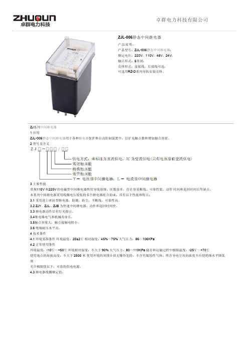
ZJL-006静态中间继电器产品说明:产品型号:ZJL-006静态中间继电器;额定电压:220V ,110V ,48V ,24V ;触点形式:6常闭;壳体形式:前接线,后接线可选;可选用RZ-D 系列导轨安装壳体。
ZJ 系列中间继电器1 应用ZJL-006静态中间继电器用于各种继电器保护和自动控制装置中,以扩充触点数和增加触点容量。
2 型号及含义3 主要性能常规110V 和220V 的电磁型中间继电器所用导线很细、匝数很多,存在容易断线、可靠性低、动作 时间和返回时间长等缺点。
本系列中间继电器采用线圈电压较低的多个继电器组合而成,具有以下性能和特点:3.1 采用进口密封型继电器,防潮,防尘,不断线,可靠性高。
3.2 ZJY 、ZJL 、ZJB 为快速中间继电器,动作和返回时间快。
3.3 继电器动作后有灯光指示。
3.4继电器电气和机械寿命长。
3.5触点容量大,触点接触电阻小。
3.6 绝缘耐压水平高。
4 技术条件4.1 环境基准条件 环境温度:20±2℃ 相对湿度:45%~75% 大气压力:86~106KPa4.2 正常使用条件环境温度:-10℃~+50℃ 环境相对湿度:不大于 90% 大气压力:80~110KPa 储存和运输过程中极限温度:-25℃~+70℃使用地点的海拔高度:不大于 2500 米 使用环境的周围介质无爆炸危险;不含有腐蚀性气体;所含导电尘埃的浓度不应使绝缘水平降低到允许极限值以下;可靠的供电电源。
4.3 继电器线圈额定值:卓群电力科技有限公司4.4 特性参数动作值和保持值直流电压型:不大于70% 额定电压,不小于50% 额定电压。
交流电压型:不大于70% 额定电压,不小于30% 额定电压。
直流电流型:不大于70% 额定电流,不小于40% 额定电流。
返回值:不小于5% 额定值。
ZJY、ZJL、ZJB 系列快速中间继电器动作和返回时间:不大于 20mS。
0.1S~10S,级差0.1S4.5 触点最大容量:切断负载能力:直流 250V 以下,τ=5ms,感性负载 50W,阻性负载 150W;交流 250V 以下,负载 1200VA;允许长期接通电流:5A。

BM037BM035BM033BM031Robust Enclosure;Premium Plating & Low Leakage PCBSuperior Immunity To Interference;Reliable Operations And Readings;Meets The Latest EN61326-1 EMC Features Non-Contact (NCV) & Single-Probe Voltage Detection For Identifying Live Lines;Added User Selectable Hi/Lo SensitivitiesDUAL SENSITIVITIES EF-DETECTION PATENTED AmpTip TM CAT III 600V & CAT IV 300V Up To 600V AC Measures Up To 600V DC AmpTip TM REGULAR CURRENT Features 600A Extra-slim Jaws ACA ModelsAnd Hall-effect Jaws ACA/DCA ModelsMAX CONDUCTOR SIZE 26mm, 600Amps Fast Captures In-rush +/- Peak SignalsAt Durations As Short As 5ms;Automatic APO Disable Feature CREST MaxMin IN-RUSH CURRENTS Records Max & Min Readings Over Time;Automatic APO Disable Feature REC MaxMin DISPLAY READINGS REL For Convenient Readings Comparison;DC_Zero For DCA Residue Offset (BM037 & 035)RELATIVE ZERO & DC_ZERO Freezes The DisplayingReading For Later View DATA HOLD Short-Beep Alert On Forward Voltages <0.85V;Beep & Backlight Effects For Shorted DiodesINNOVATIVE BeepLit TM DIODE TEST Best Resolution 0.1Ω At 600Ω Range;2 Auto-ranges Up To 6k Ω (BM035 & 031);5 Auto-ranges Up To 6000k Ω (BM037 & 033)RESISTANCE Quick Open-short Tests On Switches And Wires;Beep & Backlight Effects For Noisy EnvironmentsINNOVATIVE BeepLit TM CONTINUITY For HVAC Flame SensorsTesting Via Test Probes DCµA (BM037 & 033)2 Auto-ranges Up To 2500µFTo Measure Motor Capacitors CAPACITANCE (BM037 & 033)Selectable ºC And ºF Readings;Comes With Bkp60 Bead ProbeTYPE-K TEMPERATURE (BM037 & 033)Up To 6kV 1.2/50µs Lightning Surge;Fully Certified By Independent Test Lab;Years Of Credibility For Serious UsersTRANSIENT PROTECTION Compact AC/DC 600A! Cat-III 600V! AmpTip TM ! Precise Rotary Switch!Compact AC/DC 600A! Cat-III 600V! AmpTip TM ! Precise Rotary Switch!AmpTip TM To Fit, Accurate To Read, Compact To Carry, Safe To Trust, Reliable To Last Body width <50mm For Handy Operations, Overall Length <190mm For Easy CarryingELECTRICAL SPECIFICATIONS Accuracy is ±(% reading digits + number of digits) orotherwise specified, at 23°C ± 5°C.Maximum Crest Factor < 2 : 1 at full scale & < 4 : 1 athalf scale or otherwise specified, and with frequencyspectrum not exceeding the specified frequency bandwidth for non-sinusoidal waveforms.Indication: Bar-graph segments & audible beep tones proportional to the field strength Detection Frequency: 50/60Hz Detection Antenna: Inside the top side of the stationary jaw Probe-Contact EF-Detection: For more precise indication of live wires, such as distinguishing between live and ground connections, use one single probe to test via terminal COM for direct metal Probe-Contact EF-Detection to achieve the most distinctive indication.RANGE 600.0V 1.0% + 5dAccuracyDC VoltageInput Impedance: 10M Ω, 100 pF nominalRANGE AccuracyAC Voltage (with Low-Pass Filter)Open Circuit Voltage: < 3.5VDC typically Short Beep Alert Threshold: Drop across 0.850VBeepLit™ ON Threshold: < 0.100VAudible Indication: Beep soundVisible Indication: LCD Backlighttemperature of the ambient (isothermal stage) for a correct junction voltage compensation. Allow the meter and the type-K probe set to reach isothermal stage for a significant change of ambient temperature. It can take up to an hour for changes > 5°C. 2)Type-K thermocouple range & accuracy notincluded TM conductor: <0.01A/A for BM037 & BM035<0.06A/A for BM033 & BM031TM conductor: <0.01A/A 2)Specified with DC-Zero mode applied to offset the non-zero residual readings, if any 3)Add 5d to the specified accuracy @ < 4A 1.5% + 5d 600.0A conductor: <0.1A/A for BM037 & BM035 <0.6A/A for BM033 & BM031 2)For BM033 & BM031, specified accuracy is for measurements made at the jaw center. When the conductor is not positioned at the jaw center, add 2% to specified accuracy for position errors conductor: <0.1A/A 2)Specified with DC-Zero mode applied to offset the non-zero residual readings, if any 1)DC-bias, if any, not more than 50% of Sine RMS BeepLit™ Continuity Tester:Continuity Threshold: Between 30Ω and 480ΩContinuity ON Response Time: 15ms approx.Audible Indication: Beep soundVisible Indication: LCD BacklightCREST (Peak-Hold): Applicability: Voltage and Non-invasion Current functions Accuracy: Add +/- 250 digits to specified accuracy for changes > 5ms in duration。

ZJ-600、ZJ-800型空气自净器使用维护说明书产品特征空气自净器是一种提供工作环境的空气净化单元,是简易的室内的净化设备,吊饰安装时可以进行室内空气自循环,窗式安装时可向室内不断送入净化新风,是目前医院、药厂科学实验单位经济实惠多用途的小型净化设备。
ZJ-600、ZJ-800结构示意图技术参数型号ZJ-600 ZJ-800 参数净化效率≥0.5μm尘微粒径≥99.99%(钠焰法)初阻力≤235.44Pa(24mmH2O)风速0.46m/s±20%噪音≤62dB(A)振动半峰值≤0.5μM(x、y、z方向)电源AC单相220V/50Hz最大功率400W风量600m3/h800m3/h外型尺寸740×740×540 960×740×540开孔尺寸680×680 900×680 高效过滤器规格600×600×150 820×800×150结构特征空气自净器由速效空气过滤器,风机组,高效过滤器及静压箱等部件组成,箱体内覆盖吸音材料,具有整机噪音低,结构简单,使用方便等有点。
工作原理空气自净器的风机组将预过滤器的空气吸入静压箱,并送入高效过滤器,这样洁净空气以均匀的断面风速从高效过滤器内吹出,从而形成达到要求的洁净区域。
安装1、空气自净器应安装在个经净化厂房或空调厂房内,考虑到自净器的使用寿命,建议厂房内>0.5μm的尘埃粒应该控制在3500颗/升以内。
2.空气自净器可根据余姚水平安装或垂直安装,安装地点应远离高尘源和振源。
3、空气自净器安装时,应在安装上方垫放5mm厚的乳胶海绵密封垫,保证四周密封,确保出风面的空气不短路。
使用1、为保证净化区域的洁净度,每次使用前应提前十五分钟开机。
2、洁净空气吹出面应正对需要净化的工作区,期间应避免与大面积的物品阻挡。
3、净化区域里应尽量避免明显扰乱气流的动作。

公司简介南宁康创电力科技有限责任公司座落在中国的绿城广西南宁市,位于南宁市高新技术产业开发区内,是一家从事电力试验仪器开发与生产的高新技术企业。
公司是由一批长期在电力系统从事继电保护工作具有丰富经验的调试工程师和计算机、电力电子高新技术等专业方面的专家组成,并与国内一些科研机构和大专院校形成产业战略同盟,为提高企业对市场的竞争力打下良好的基础。
公司坚持“科技创新,以人为本”的发展方针,在市场经济的大潮中,我们始终信奉:用户的需求就是我们的发展方向,我们本着可靠的产品质量、热情优质的服务、高效率的工作和良好的信誉为宗旨为广大客户服务,为电力系统技术人员提供更加便捷、可靠、准确和安全的电力系统测试工具。
目录一、产品概述 (4)二、试验仪主要功能及特点 (4)三、主要技术指标 (5)四、试验仪面板说明 (6)五、MJ600A继电保护装置试验仪快速操作指南 (9)六、仪器操作方法 (10)1 定值测试 (11)2 故障模拟 (31)3 差动试验 (36)4 变频试验 (45)5 励磁同期试验 (48)6 任意电源输出 (50)一、产品概述MJ600A继电保护装置试验仪,是我公司根据目前微机继电保护装置测试的需要,结合我公司多年研发继电保护现场试验装置的优势,以及长期从事继电保护现场试验人员的工作经验,利用目前国际上先进的嵌入式系统及DSP高速数字信号处理器的模块化设计而生产出来的新型仪器。
该装置高精度线性电流、电压放大器,具有高性能、高可靠性、高精度、低功耗的特点,是通用的新型便携式现场试验仪器。
仪器全面提供了满足继电保护及综合自动化试验所需的六相电流及六相电压源,可模拟各种电压互感器、电流互感器输出的电压和电流,并提供了四路开出量,八路开入量,方便的逻辑组合及灵活的测试功能。
可手动测试及自动测试,适合对500KV 及以下电力系统继电保护装置及综合自动化装置进行整组试验和元件继电器的试验。
MJ600A继电保护试验仪,贯穿了我公司的产品宗旨:以现场实用为本,操作简便灵活。

目录1.SJ600泵简介2.SJ600泵性能参数3.结构简介4.发运和储存5.泵的安装6.润滑系统要求7.增压系统的要求8.泵的操作和维护9.泵易损件目录10.附件及工具一、600泵简介600泵是一种往复、容积式、单作用、卧式三缸柱塞泵,该泵的最大输入额定制动功率为600HP。
该泵广泛地用于间歇式油井作业,如酸化、固井、压裂、压井等。
600泵由一个动力端总成、减速箱总成和一个液力端总成组成。
减速箱总成既可安装在泵的右侧也可安装在泵的左侧。
该减速箱输入轴有17种不同的安装位置供用户选用以适合多种泵送装置的传动系统配置的要求。
有两种不同的泵头体以适应安装几种不同规格的柱塞以获得不同压裂和排量。
用户可选用不同的盘根总成、凡尔总成、排出法兰、吸入管汇来经行各种配套布置;泵送各种特殊的液体;在各种不同环境下工作。
泵的重量不会因柱塞规格和其它选择件的不同而发生较大的变化,但将不大于说明告知重量的±5%。
600泵基本设计和结构特点如下:1.1动力端设计曲轴箱体高强度钢焊接后热处理消除应力,精密镗孔加工。
曲轴由整体合金钢锻造并热处理后加工而成。
精磨曲轴轴颈。
由4个重型圆柱滚子轴承支撑。
连杆由高强度合金钢度锻造毛坯,精加工而成。
十字头由高强度球墨铸铁毛坯,精加工而成。
十字头导向套设计成半圆柱形状,由合金铸铁精加工而成。
十字头销由和金钢热处理后精加工而成。
接杆表面喷镀耐磨合金涂层后精加工而成。
卡箍总成卡箍体由高强度合金钢精加工而成。
1.2减速箱设计箱体合金钢焊接经消除应力热处理后精密镗孔。
平行轴式设计。
大齿轮大功率斜齿轮符合AGMA#8(美国齿轮制造协会)质量标准。
由高强度合金钢精加工而成。
齿轮高频淬火。
由两个重型滚子轴承支撑。
配有W/Spicer1800/1810系列组合发兰。
1.3液力端设计泵头体整体式设计。
由高强度合金锻钢整体加工而成。
柱塞柱塞表面喷涂耐酸硬涂层后精磨加工而成。
柱塞盘根“自调”式盘根总成,精密压制纤维强化的V型压环。
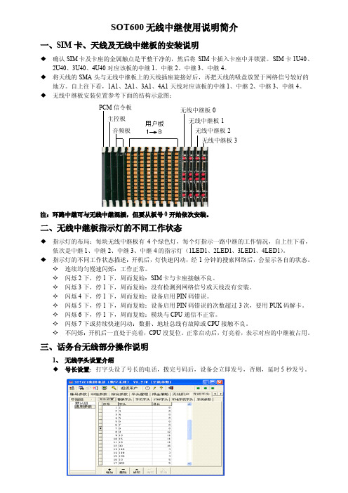
PANASONIC A406 REPEATER QUICK SETUP GUIDEOnline instructional videos and manufacturer user guides are also available. Visit www.primus.ca/hpbxguide for more information.What You NeedPanasonic base unit and cordless handset (model KX-TGP600) fromPrimus Business ServicesPanasonic DECT repeater (model KX-A406) from Primus BusinessServicesHosted PBX service from Primus Business ServicesBefore you StartYour Panasonic base unit and cordless phone must be setup, turned on, and functioning prior to installing the repeater. Please refer to the Panasonic TGP600 TPA60 TPA65 Quick Setup Guide , available at www.primus.ca/hpbxguide for more information.Registering the Repeater to the TGP600 Base Unit1. Plug the AC adapter into the repeater. Press the plug firmly to make sure itis in place. There is a hook at the bottom of the unit to secure the cable inplace to prevent it from being accidentally pulled out. Do not plug in the ACadapter into an electrical outlet yet.2. On the base unit, press and hold the Handset locator button for 4 secondsuntil the STATUS indicator flashes red. If all registered handsets startringing, press the same button to stop and repeat the step. The next stepmust be completed within 90 seconds.3. Plug the AC adaptor of the repeater to an electrical outlet.4. On the repeater, the STATUS indicator and indicator will turn amberfor 2 seconds. When both indicator lights turn solid green, the repeater isregistered to the base unit and is ready to use.5. On the base unit, exit registration mode by pressing the Handset locatorbutton.NOTE:Register repeaters one by one. Do not register multiple repeaters at thesame time.For wall mount instructions, see Panasonic DECT Repeater Installation Manual for the KX-A406, available at http://primus.ca/business/hpbxguide.For additional troubleshooting tips, please review the Hosted PBX Small Office Basic Troubleshooting Guide, available athttp://primus.ca/business/hpbxguide.If the configuration process was interrupted or if you need assistance, pleasecontact Primus HPBX Technical Support at 1-888-222-8577.Registering the Repeater to Another RepeaterA repeater can be connected to another repeater in series to extend total coverage to up to 150m. This can be done by registering the repeater to another repeater.In the diagram above, the destination repeater is registered with the base unit, and the origin repeater is connected in series to the destination repeater. This section describes how to set up the origin repeater. Before you begin, you must register the destination repeater to the TGP600 base unit. Please follow the steps in the previous section on how to register a repeater to the base unit.To register a repeater to another repeater, they must be set to the same ID.On the destination repeater:1. First check the ID of the repeater you are attempting to register to(destination repeater). With the destination repeater turned on andfunctioning normally, press the PROGRAM button located under thedestination repeater. Note the number of times the indicator flashesgreen. This is the ID of the destination repeater – one flash indicates the IDas 1, two flashes indicate the ID as 2, and so on.2. Return the destination repeater back to normal operation by pressing thePROGRAM button again. Both the and STATUS indicators should goback to solid green .On the origin repeater:3. Turn on the repeater you want to register (origin repeater) by connecting theAC adaptor. The STATUS indicator should be flashing red and theindicator should be off.4. On the origin repeater, press and hold the PROGRAM button for 5 secondsuntil the STATUS indicator flashes green . Release the PROGRAMbutton.(Destination Repeater) (Origin Repeater)flash red once to indicate that the ID is set to 1.5. Set the ID of the origin repeater to be the same as the destination repeater.If the ID of the destination repeater was not 1, press the PROGRAM buttonon the origin repeater to select the ID that matches the destination repeater.The ID will change by one each time the PROGRAM button is pressed.(e.g., if you select ID 3 by pressing the button two times, the indicatorwill flash 3 times)6. Press and hold the PROGRAM button for 5 seconds to assign the ID to theorigin repeater. The indicator will turn solid red. Release thePROGRAM button. The STATUS indicator and the indicator will turnamber for 2 seconds and then the STATUS indicator will start flashing red,indicating that the repeater is waiting to be found.On the base unit:7. On the base unit, press and hold the Handset locator button for 4 secondsuntil the STATUS indicator flashes red.8. Once the destination repeater finds the origin repeater, the STATUSindicator on the origin repeater will turn solid green. Registration issuccessful.9. On the base unit, exit registration mode by pressing the Handset locatorbutton.10. To verify whether the setup was successful, turn off the destination repeaterby unplugging the AC adapter. On the origin repeater, the STATUS indicatorconnection was lost. Turn the destination repeater back on by plugging inthe AC adapter. Both indicators on the destination repeater should turnsolid green, followed by the indicators on the origin repeater.Optimizing Placement of the RepeaterThe TGP600 base unit and A406 repeater has a maximum range of 50 meters. However, for optimal synchronization between the base unit and the repeater, or between two repeaters, the devices are recommended to be placed within a maximum of 40m to 50m of each other. Range may vary depending on environment. For maximum coverage and noise-free communications, place your repeater: •at a convenient, high, and central location, such as on a wall, with no obstructions between your phones and the repeater;•away from electronic appliances such as TVs, radios, personal computers, wireless devices or other phones;•away from radio transmitters such as external antennas of mobile phone cell stations (avoid putting the repeater on a bay window or near a window);•away from objects that could interfere with reception such as wire fences, thick walls, radiators, and metal shelving.The repeater is for indoor use only.To optimize the placement of your repeater:1. Use the signal strength indicator on the TGP600/TPA60 cordless handset todetermine a viable location where you wish to extend the range of your base unit. The signal strength should still be strong where the repeater will beplaced.2. Once a suitable location for the repeater is found, turn on the repeater byconnecting the AC adaptor. If the indicator on the repeater turns red oramber, this indicates that the signal strength is too weak for the repeater tofunction. Re-position the repeater to a place where the indicator turnsgreen.3. Check that that repeater is providing adequate coverage for your needs.Using the signal strength indicator on the TGP600/TPA60 cordless handset,walk to various areas where you may be using the phone, and confirm there is adequate signal strength. If not, you may need to adjust the position of therepeater, or install another repeater to further extend coverage area.Optimizing Placement of the Repeater (Advanced)The following instructions are for advanced users conducting a site survey to determine the optimal placement of the repeater. These steps require the cordless handset to operate in maintenance mode.1. Press and hold the “power” key on the cordless handset until thebackground of the display screen is light grey.2. Release the “power” key and press and hold the “talk” key for about 10seconds until the background of the display screen turns dark grey.3. Release the “talk” key and press the following keys in sequence: Left softkey, 8, 1. The display will show “Maintenance Mode”, with the firmwareversion below it. Press “OK” to display the maintenance menu.4. Then select “Base Monitor” and then “Current Base”.5. Turn off the handset by pressing the “power” key, and then turn it back onby pressing the “power” key. The handset will now be in site survey mode, and display signal strength (RSSI) and connection status. Description of thevalues are as follows (PS refers to the handset):6. Walk around to confirm the service area. If the readings are acceptable, thedisplay will remain green. If the display turns red and the signal is weak,install the repeater in the area right before it starts turning red.7. Once the site survey is complete, revert the handset back to normaloperation. First, turn off the handset.8. Go into Maintenance Mode by following steps 1 to 3.9. Select “Base Monitor” and press “OK”.10. Select “OFF” and press “OK”.11. Turn the handset off and then turn it back on. The handset will be in normaloperation mode.11 PRIMUSBUSINESS.CAPRIMUS BUSINESS SERVICES | HOSTED PBX | PANASONIC A406 REPEATER QUICK SETUP Status Light Indicators STATUS IndicatorSolid Green The repeater is within base unit range, or within range ofanother repeater (if connected in series). The repeater isready for useFlashing Green One handset is communicating with the base unit throughthe repeaterQuick Flashing Green Two handsets are communicating with the base unitthrough the repeaterSolid Red The repeater is out of range of the base unit or anotherrepeater (if connected in series)Flashing Red The repeater is not registered to the base unit.Off The repeater power is off.Signal Strength/ID IndicatorSolid Green Signal strength of the base unit is strongFlashing Green The base unit is in repeater range.The number of flashes indicates the current ID of therepeater. When it flashes once, the ID is 1.Solid Amber Signal strength of the base unit is weakSolid Red The repeater is out of range of the base unit or anotherrepeater (if connected in series)Flashing Red The base unit not within repeater range.The number of flashes indicates the current ID of therepeater. When it flashes once, the ID is 1.Off The repeater is not in use.。
前言EH60 0A系列变频器是深圳市西林电气技术有限公司推出的新一代高性能变频器。
EH600A是将客户通用需求与客户个性化需求、行业性需求有机融合的革命性产品,实用的PI、简易PLC、灵活的输入输出端子、停电参数存储选择、主辅给定控制、摆频控制、创新的精确停机模式(定长/计数器/定时控制)、内嵌Modbus标准协议,双排LED显示,完善的用户密码保护,为设备制造业客户提供高集成度的一体化解决方案,对降低系统成本,提高系统可靠性具有极大价值。
EH600A通过优化PWM控制技术和电磁兼容性整体设计,满足用户对应用场所的低噪音、低电磁干扰的环保要求。
本手册提供用户安装配线、参数设定、故障诊断和排除及日常维护相关注意事项。
为确保能正确安装及操作EH600A系列变频器,发挥其优越性能,请在装机之前,详细阅读本使用手册,并请妥善保存及交给该机器的使用者。
开箱时,请认真确认以下内容:1、产品在运输过程中是否有破损,零部件是否有损坏、脱落现象,主体是否有碰伤现象;2、本机铭牌所标注的额定值是否与您的订货要求一致,箱内包含您订购的机器、用户操作手册。
本公司在产品的制造及包装出厂方面,质量保证体系严格,但若发现有某种检验遗漏,请速与本公司或您的供货商联系解决。
目录第一章安全及注意事项1.1安全事项 (1)1.2注意事项 (2)第二章产品信息2.1命名规则 (3)2.2铭牌 (3)2.3 EH600A变频器系列 (4)2.4技术规范 (5)2.5变频器和操作面板的外型及安装尺寸 (6)2.6选配件 (8)2.7变频器的日常保养与维护 (9)2.8变频器的保修说明 .......................................................... *10 2.9选型指南 ........................................................................... .10 2.10制动组件选型指南. (11)第三章机械与电气安装3.1机械安装 (12)3.2电气安装 (13)第四章操作与显示4.1操作与显示界面介绍 (19)4.2功能码查看、修改方法说明 (20)4.3状态参数的查看方法 (21)4.4数字设定在线修改操作 (21)4.5密码设置 (21)4.6提示信息.............................................................................. 21 第五章功能参数表.... 22 第六章参数说明F0组基本功能组 (36)F1组电机参数 (37)F2组V/F控制参数 (38)F3组输入端子 (39)F4组输出端子 (42)F5组启停控制 (44)F6组键盘与显示 (45)F7组辅助功能 (47)F8组故障与保护 (49)F9组PID功能 (50)FA组摆频、定长、计数和定时 (53)FB组多段速功能及简易PLC功能 (55)FC组通讯参数 (56)FD组特殊功能 (56)FV组状态参数 (57)第七章故障诊断及对策7.1故障报警及对策 (58)7.2常见故障及其处理方法 (65)第一章安全注意事项第一章安全及注意事项安全定义:为了确保您的人身、设备及财产安全,在使用我公司变频器之前,请务必仔细阅读本章内容。
ZJ600A 系列装置概述1、简介ZJ600A 系列保护测控装置是在多年实践应用和运行经验的基础上,吸取了国内外微机保护装置现有的先进技术,研制推出的新一代微机保护测控装置。
广泛适用于电力、水利、石油、化工等行业35KV及以下电压等级系统,作为各种电气设备的主保护或后备保护。
ZJ600A 系列装置针对不同的客户需求而设计。
ZJ600A系列兼有保护、测控、通讯功能,满足35KV及以下变电站综合自动化的需求;可集中组屏安装或直接在开关柜上分散安装,配合通讯管理单元和监控系统,还可以构成完整的厂站自动化系统。
针对不同的被保护对象,装置的型号分类如下:ZJ600A系列保护测控装置ZJ601A 线路保护测控装置ZJ602A 低压变压器保护测控装置ZJ603A 电容器保护测控装置ZJ604A 备自投及分段保护测控装置ZJ605CA 电动机差动保护装置ZJ605A 电动机综合保护测控装置ZJ606A PT保护及并列装置2、特点■先进的32位高速处理器,强大的运算判断处理能力。
■中文液晶显示,人机界面友善、操作方便。
■采用多层印制板及表面贴装技术,强弱电严格分离,达到高标准电磁兼容性能。
■采用高分辨率采样芯片,精度高,测量精确。
■采用高可靠性设计,并具有完善的自检功能。
保证装置可靠运行。
■体积小、重量轻,可集中组屏,也可分散安装在开关柜上。
■ ZJ600A系列保护测控装置具有高速CAN网或RS485等通讯接口,方便与各类监控系统及其他智能设备连接通讯。
3、技术指标额定参数交流电流5A或1A(订货说明)交流电压100V/400V(订货说明)交流频率50Hz直流工作电源95~260V交流工作电源85~265V / 50Hz开入电源强电DC110V,由装置自身提供功率消耗交流电流回路In = 5A(每相不大于0.05VA)交流电压回路U = Un(每相不大于0.05VA)电源回路正常工作不大于15W保护动作不大于20W过载能力交流电流回路2倍额定电流连续工作10倍额定电流允许10s 20倍额定电流允许1s交流电压回路 1.2倍额定电压连续工作直流电源回路0%~120%额定电压连续工作电流元件动作电流0.1In ~ 20In 级差0.01A误差<3%电压元件动作电压0.5V ~ 120V 级差0.1V误差<3%频率元件动作范围45Hz ~ 55Hz 滑差闭锁范围0.5Hz ~ 5Hz/s 级差0.01Hz时间元件工作范围0 ~ 99.99S 级差0.01S误差10ms测量精度电流、电压0.2级有功、无功0.5级遥信分辨率1ms温度范围正常工作-10℃~ 55℃正常储存-25℃~ 70℃安全与电磁兼容能承受频率为1MHZ及100KHZ电压幅值共模2500V,差模1000V的衰减震荡波脉冲干扰试验能承受IEC61000-4-2标准Ⅳ级、试验电压8KV的静电接触放电试验能承受IEC61000-4-4标准Ⅳ级的快速瞬变干扰试验能承受IEC61000-4-5标准Ⅳ级、开路试验电压4KV的浪涌干扰试验能承受IEC61000-4-10标准Ⅳ级阻尼振荡磁场干扰试验4、主要功能4.1、保护功能装置适用于35KV及以下电压等级的发电厂及变电站,功能涵盖了电力变压器保护、线路保护、电容器保护、电动机保护等。
具体保护功能介绍参见后续章节中相应型号保护装置的说明部分。
装置工作电源交直流通用,工作电压范围为95V~260V(AC或DC);开入回路采用装置自身提供的DC110V电源;继电器出口均为空接点,可直接接入交流或直流控制回路。
ZJ600A系列装置还配置了独立的防跳回路。
防跳回路分为DC220V、DC110V、AC220V等多个版本,可以满足各种现场的控制电源类型。
因此,ZJ600A 系列装置不受工作电源、控制电源类型的限制,可在各种常见电源条件下可靠工作。
4.2、测量功能装置可实时采集测量电压、测量电流、频率、有功功率、无功功率及功率因数。
ZJ600A系列保护测控装置设有10路开关量接口 ,开入量电源为装置自身输出的直流强电DC110V电源。
可用于采集断路器位置接点、刀闸位置接点、保护压板接点、外部闭锁接点等开关量。
4.3、控制功能ZJ600A系列装置可接收远方遥控命令进行断路器的分闸、合闸控制操作。
也可通过装置键盘菜单操作对断路器进行手动分闸、合闸控制操作。
ZJ600A系列装置提供了一个名称为“闭锁遥控”的开入回路,可以将外部的“远方/就地”切换开关位置接点接入该回路,来实现对远方遥控操作的闭锁。
当切换开关在“就地”位置时,由通讯发来的遥控分闸和遥控合闸命令被禁止执行,当切换开关在“远方”位置时,由通讯发来的遥控分闸和遥控合闸命令被允许执行。
装置默认接入的是“就地”位置接点,当实际接入的是“远方”位置接点时,可以将定值项中的“闭锁遥控开入取反”控制字投入,从而实现相同的闭锁功能。
保护定值的修改、保护功能的投退均可由远方遥控进行。
4.4、事件报告功能装置具有事件报告记录功能,可以将发生的重要事件生成报告保存,装置失电后报告不丢失。
装置事件的存放采用循环方式,即有最新事件报告保存时,最老的事件自动被删除。
动作事件报告的内容为装置发生保护动作的保护类型、保护动作的发生时间、以及保护动作时刻的故障量数据。
4.5、故障录波功能ZJ600A系列装置具有故障录波功能,可以将系统发生故障时的故障量进行录波保存,录波数据为8个周波的实时采样数据。
录波数据可以由通讯接口传送到上位机监控系统,在监控系统软件中可以显示录波数据和波形。
装置可以保存最近4次保护装置发生动作的故障录波报告,装置电源关闭后录波数据不丢失。
第一章ZJ601A线路保护测控装置ZJ601A线路保护测控装置适用于35KV及以下电压等级的线路保护、测量及控制。
1 主要功能1.1 保护功能■电流速断保护■二段式电压元件闭锁的定时限过流保护■反时限过流保护■二段式定时限零序过流保护■反时限零序过流保护■后加速保护■小电流接地告警■过负荷保护■低压解列■三相一次重合闸■ PT断线监测■零序过压告警1.2 测控功能■遥信:10路外部开关量遥信输入■遥测:电压、电流、有功、无功、功率因数、频率■遥控:断路器遥控分闸、合闸接点输出1.3 通讯功能装置具有高速CAN网和RS485通讯接口,可以与厂站自动化系统及智能设备连接通讯。
2 保护功能2.1 相间过流保护相间过流保护配置了速断保护、二段式电压元件闭锁的定时限过流保护以及独立的反时限过流保护。
2.1.1 低电压元件当三个线电压中的任意一个小于低电压定值时,低电压元件就动作,开放过流保护。
利用低电压元件可以保证装置在电机反向充电等非故障情况下不出现误动作。
2.1.2 三相过流元件装置实时进行电流速断及二段式过流保护判别。
当任意一相电流大于定值,装置保护逻辑将立即启动,经历整定的延时后出口跳闸。
电流速断保护出口跳闸的最短延时不大于40ms(包括继电器的固有动作时间)。
为了躲开线路避雷器的放电时间,本装置中电流速断保护也设置了可以独立整定的延时时间。
装置在执行二段式过流判别时,各段判别逻辑一致,其动作条件为:● IΦ> Idn ;Idn 为各段电流定值, IΦ为相电流;● T > T dn ; Tdn为各段延时定值;●相应过流相的低电压条件满足(若投入);2.1.3 反时限元件反时限保护元件是动作时限与被保护线路中电流大小自然配合的保护元件,通过平移动作曲线,可以非常方便的实现全线路的配合。
本装置提供三种反时限方式(依据IEC225-4标准),可以通过整定控制字选择其中一种,构成反时限过流保护。
一般反时限 非常反时限 极端反时限1)(14.002.0-=P P I I T t 1)(5.13-=P P I I T t1)(802-=P PI I T t其中:P T 为时间常数,范围为(0.05~1); P I 为启动电流,I 为故障电流; t 为跳闸时间。
本装置相间过流及零序过流均带有定、反时限保护功能,相间过流反时限、零序过流反时限动作条件为:● I > I P ;I 为故障电流定值(相电流或零序电流),I P 为启动电流; ● T > t ;t 为跳闸时间;2.2 零序过流保护本装置配置二段式定时限特性以及独立的零序反时限过流保护。
2.2.1 零序过流元件零序过电流元件的实现方式与过流元件相同。
装置零序过流一段(瞬动段)出口跳闸的延时不大于40ms (包括继电器的固有动作时间)。
本装置中零序过流一段也设置了可以独立整定的延时时间。
装置在执行二段式过流判别时,各段判别逻辑一致,其动作条件为: ● I0 > I0n ; I0n 为零序n 段电流定值(n = 1,2), I0 为零序电流; ● T > T0n ; T0n 为零序n 段延时定值(n = 1,2); 2.2.2 零序过流反时限方式零序过流反时限方式与相间过流反时限方式相同。
(参见过流反时限元件)2.3 小电流接地告警小电流接地告警是针对不接地系统或小电流接地系统而设计的。
当检测到接地零序电流大于接地告警定值时发出告警信号。
动作条件为:● I0 > I0jd ; I0jd 为接地电流定值,I0 为零序电流; ● T > T jd ; Tjd 为零序接地告警延时值;2.4 后加速保护加速回路包括手合后加速及重合闸后加速,有独立的电流定值及相应的时间定值可以整定。
为保证重合到永久性三相短路后可靠跳闸,后加速不经方向元件闭锁。
装置的手合加速回路不需由外部手动合闸把手的触点来启动,此举主要是考虑到目前许多厂站采用综合自动化系统后,已经取消了控制屏,在现场不再安装手动操作把手,或仅安装简易的操作把手。
考虑到合闸后可能不立即故障,后加速元件展宽3秒。
手合加速回路的启动条件为:● 断路器在分闸位置的时间超过15S ;● 断路器在分闸变为合闸,加速允许时间展宽3S 。
后加速保护还可用作母联的充电保护,只需将“过流后加速保护”压板投入,整定“过流后加速电流”及“过流后加速时间”定值即可实现。
在实际运用中,某些变电站不需要备用电源自投功能,而只需要分段开关的过流保护和充电保护,可以用本装置来完成分段开关的过流保护和充电保护功能。
2.5 过负荷保护过负荷保护可通过整定控制字选择发信或跳闸。
过负荷元件监视三相电流,当有任一相电流大于定值,经设定的延时后动作,动作方式为跳闸或告警可选。
2.6 低压解列利用本装置的低压解列元件可以实现低压控制。
为防止装置上电时母线PT无压而引起低压解列保护动作,装置在检测到母线PT有压(三相线电压均大于70V),并且开关在合位3秒后才投入低压解列保护。
为了防止由于人为误断开连接交流小母线的空气开关,而使装置在PT断线告警前误动作,程序设定了10V的门槛电压。