Snapdragon_8660_MDP_Quick_Start_(042611)
- 格式:pdf
- 大小:162.64 KB
- 文档页数:2
Title 高通驱动安装及工具使用Page No. 1 Of 25一.USB驱动安装:将手机开机,用数据线将手机与电脑连接。
要保证在安装驱动过程中手机能一直保持开机状态。
安装驱动时可在设备管理器上看到驱动安装状态(右键单击‘我的电脑’----左键单击‘管理’栏----在计算机管理中找到设备管理器并单击就可看到)。
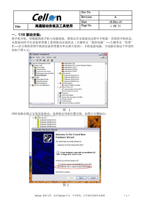
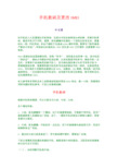
手机连接电脑,当电脑识别这个外设时如如下图1示:图 1同时电脑会提示安装设备驱动,选择指定列表位置安装,如图2红圈标注:图2Title 高通驱动安装及工具使用Page No. 2 Of 25图2中单击下一步后会弹出图3提示框,选择指定位置寻找(红圈所示),然后点击‘Browse’指定驱动位置如图4所示。
目前高通USB驱动文件夹默认是【30_USB_Driver----WinXP---checked】图3图4选择好驱动地址后点击OK就开始安装驱动了,如图5所示:Title 高通驱动安装及工具使用Page No. 3 Of 25图5当出现图6所示提示框,点击continue Anyway继续安装:图6Title 高通驱动安装及工具使用Page No. 4 Of 25安装驱动时会连续提示安装3次,每次都点击continue Anyway图7图8当驱动安装完成后,在设备管理器里找到端口和调制解调器就表示安装成功了,如图9所示:Title 高通驱动安装及工具使用Page No. 5 Of 25图9二.QPST安装安装了USB驱动只是手机与PC间能通讯,要使手机能与高通工具实现连接还需要安装QPST并加入端口才行。
找到QPST安装文件QPST.2.7.362,如图10双击setup开始安装:图 10开始安装如图11,点击install:Title 高通驱动安装及工具使用Page No. 6 Of 25图 11图 12安装到如图13所示,点击‘Next>’:图 13Title 高通驱动安装及工具使用Page No. 7 Of 25 到图14选择‘I Agree’并点击‘Next>’:图 14然后会弹出图15界面,选择‘Everyone’再点击‘Next>’:图 15进行到图16继续点击‘Next>’:Title 高通驱动安装及工具使用Page No. 8 Of 25图 16安装继续进行中:图 17安装完成,如图18:Title 高通驱动安装及工具使用Page No. 9 Of 25图 18安装完成后,点击快捷方式图标,并在‘ports’栏中找到识别的USB端口,这样就能用高通工具对手机进行控制了。
手机救砖及更改IMEI叶长青玩手机的人大多遇到过手机变砖,这是令手机玩家特别头疼的事。
所谓手机变砖,就是手机开不开机,黑屏,按电源键手机振动一下或完全没有反应,就像砖头一样。
手机变砖,多由于刷机不当造成ROM损坏所致,需要专门软件修复,严重的只有返厂。
有些砖头机救活后,IMEI丢失或IMEI文件损坏,这就需要IMEI 恢复。
IMEI是移动设备国际辨识码,俗称“串号”,该码是全世界唯一的,是手机的“身份证”。
移动公司绑定手机送话费,认定的就是手机串号。
绑定手机一旦丢失,话费将不会送给你的新手机上,因为移动服务器只认串号而非手机卡,要想继续送话费,就需要把新手机的串号改成和绑定手机一样的,这就是更改IMEI。
另外现在大多数网站需要认证IMEI,如微信、QQ等等,特别是一些手机威客网站,一旦注册时的老手机丢失,改用新手机将无法登陆,账号资料丢失,这也需要更改IMEI。
本文参考有关资料及本人实际救砖经验和更改IMEI体会,做一小结,供遇到过同样问题的朋友参考,不妥之处敬请谅解。
手机救砖根据手机变砖程度,可以大致分为小砖、中砖、大砖。
各个情况形容:1、小砖:按电源键有一下震动,这个时候需要线刷。
可根据不同手机,采用厂家线刷恢复工具刷回出厂状态,这个,一般玩手机的朋友只要细心操作,很容易就可以救活。
2、中砖:按电源键,手机没有一点反应。
这个时候需要先刷底层文件,再进行线刷恢复出厂状态。
3、最后的大砖已经是真砖了,有可能是硬件损坏,需要返厂处理。
下面以普遍采用高通处理器的手机,着重谈谈中砖的救法。
【联发科处理器救砖方法可自行百度】(一)、如何判断手机是中砖。
1、在电池电量足够的情况下,手机按住三键组合或按电源键都无法开机,屏幕没有任何显示,为黑屏状态。
2、插上手机数据线,电脑的设备管理器里多出了一个其它设备,名称为“QHSUSB_DLOAD”,并且有感叹号。
这是没安装高通驱动之前的原始状态。
3、安装了高通驱动之后,之前的“QHSUSB_DLOAD”设备变成“Qualcomm HS-USB QDLoader 9008 (COMx)”,其中COMx不固定,有可能COM10也可能COM260或其它。

Camera Card ConnectorsWiGig ModuleSensor ExpansionHDMIPower SwitchType C USBAudio CardConnectorsVolumeAMOLED 5.5" display with T ouch PanelJTAGAPQ8098 ProcessorCard NFC ExpansionSolution HighlightsMaterials are subject to change without notice.87-PD100-1 Rev BComprehensive and expandable development and evaluation kit for the Snapdragon 835 Mobile Platform.The Snapdragon 835 Mobile Hardware Development Kit provides an open-frame solution for technology companies tointegrate and innovate devices based on the Snapdragon 835 Mobile Platform.The Snapdragon 835 Mobile Hardware Development Kit is a feature-rich Android development platform that is designed to provide an ideal starting point for creating high-performance mobile devices and applications based on the Snapdragon 835 Mobile Platform. The kit includes the hardware, software tools and accessories needed to immediately begin your mobile development work.With an advanced 10-nanometer design, the Snapdragon 835 Mobile Platform can support phenomenal mobile performance. It is 35% smaller and uses 25% less power than its predecessor and is engineered to support exceptionally long battery life, lifelike VR and AR experiences, cutting-edge camera capabilities and Gigabit Class download speeds.The Snapdragon 835 mobile development platform is designed to provide original equipment manufacturers (OEMs),hardware/software vendors, developers and engineers with next generationsoftware technology and tools to accelerate development and testing of devices.Kit ContentsProcessor Card wtih APQ8098 Mini-ITX carrier board GNSS card12V AC power adapter Battery (optional) Charger USB cableSetup guideDisplay Adapter Card is an additional accessoryDevelopment PlatformQualcomm Snapdragon and APQ8098 are products of Qualcomm T echnologies, Inc. and/or its subsidiaries.Snapdragon 835 Processor CardThe Snapdragon 835 Processor Card measuring 60mm x 70mm is where all the processing occurs. It is connected to the carrier via two 240-pin high speed board-to-board connectors. A top side heat sink and a bottom side heat conductive metal plate provide thermal protection.The Processor Card provides the basic common set of features with minimal integration effort. It integrates the following: Snapdragon 835 (APQ8098) mainapplication processorLPDDR4X up to 1866MHz 4GB RAM (POP) PMi8998 + PM8998 – PMIC forPeripheral LDOs, Boost RegulatorsWCN3990 Wi-Fi+ BT+ FM combo chipover SLIMbus, Analog IQ, UART, PCM128 GB UFS 2.1WCD9341 Audio Code Dimensions170mm x 170mm Mini-ITX CPU Quad-core Qualcomm® Kryo™ 280 CPU64-bit ARMv8-compliant processor at up to 2.2GHz GPU Qualcomm® Adreno™ 540 GPUOpenGL ES 3.2, OpenCL 2.0 Full, Vulkan, DX12 DSP Qualcomm® Hexagon™ 682 DSP Memory and Storage4GB LPDDR4X PoP memory128GB UFS 2.1 Connectivity Wi-Fi: 802.11a/b/g/n/ac 2.4/5GHzBluetooth 5.0 + HS (backward compatible)GNSS (GPS/GLONASS/COMPASS/GALILEO) Camera Support3x MIPI CSI with support for 3D camera configuration Display2x MIPI dual 4-lane DSI + touch panel Multimedia HDMI 2.0 output - supports up to 4K UHD(3840 x 2400 at 60fps)and HDMI 2.0a (4K60)/ 4K30 Miracast I/O Interfaces1x PCIe, 1x JTAG, HDMI 2.0, 1x USB 3.1 Type C,1x USB 2.0 micro-B, 3x MIPI-CSI, 2x MIPI dual 4-lane DSI 4x Expansion headers for additional features (NFC, sensors etc.) LED3x General purpose LED, PMIC driven Battery 4.35V/3000mAh Operating System Android 7 Optional Accessories Display: 5.5” AMOLED LED (1440 x 2560)with PCAP Touch PanelCameras: 8M FF, Single 12M 2PD, Dual 12M+13M OZ+OIS SpecificationsWCN3990, WCD9341, PMi8998, PM8998, Qualcomm Hexagon, Qualcomm Adreno and Qualcomm Kryo are products of Qualcomm T echnologies, Inc. and/or its subsidiaries.©2018 Qualcomm T echnologies, Inc. All Rights Reserved. Qualcomm, Snapdragon, Hexagon, Kryo and Adreno are trademarks of Qualcomm Incorporated, registered in the United States and other countries. Other products and brand names may be trademarks or registered trademarks of their respective owners. 0318AT o learn more visit:。


⾼通MSM8Kbootloader之四:ramdump前⾯说过⾼通平台,系统crash发⽣时,抓取crash ramdump⾮常重要,否则很难定位crash原因。
平台默认抓取ramdump的⽅法都有很强的局限性,如下:1、PC端⼯具QPST提供的 Memory Debug Application⼯具。
局限性:完全信赖PC2、sbl1将crash现场dump到外置sdcard。
boot_sd_ramdump.c局限性:很多⼿机根本没有配置外置sdcard。
3、今天再看⾼通代码,还有种ram dump ⽅法,直接dump到raw partition :boot_raw_partition_ramdump .cboot_procedure_func_type sbl1_pre_dload_procs[] ={............/*-----------------------------------------------------------------------* Ram dump to eMMC raw partition, this function will reset device* after successful dump collection if cookie is set*----------------------------------------------------------------------*/(boot_procedure_func_type) boot_ram_dump_to_raw_parition,#ifdef FEATURE_BOOT_RAMDUMPS_TO_SD_CARD/*----------------------------------------------------------------------* Take the Ramdumps to SD card if cookie file is* present in SD card*---------------------------------------------------------------------*/boot_ram_dumps_to_sd_card,#endif /*FEATURE_BOOT_RAMDUMPS_TO_SD_CARD*/NULL};对于没有外置sdcard的⼿机,我考虑按如下⽅法改进ramdump机制,⼤概思路如下:1、emmc分区添加⼀个400M左右的新分区,格式化成fat⽂件系统。

最近老是有人在问什么机手机指令多少,下面是我收集到的所有的MTK手机指令,还不完整,为了方便大家,望兄弟们把知道的补充一下。
*#66*#*#3646633#*#36*#*#65289*#*#8560968#*#82043036#有一些机器开机输入*#66*#不进测试的。
可以在开机瞬间,在按键灯亮和开机音乐响的时候快速按*#*#............*#就可进入测试下面几个是国产机常用的工程模式指令,大家可以参考一下!注意有的是无卡状态输入的.特别提示:对于一些指令可能会使手机进入一些未知的状态,在这种情况下,心中无底的话,最好不要冒险继续操作.*888*888#*2580*#*888*888#**1234#**80#**#237546#**0106#*#9960#*983*0#*#0324#*888*888##*80#*528*0#*#*#1705*#369# hh hsf*789再长按#*#301#01*#123321#**#3012945#*#*#*#1705#MT6225齐乐D600手机可用*#4853*#天基168.芯片是MTK6225 #6803#.仿苹果ciphone工程模式*#83646633#;*#83656565#埃利特仿苹果机*#83646633# *#23642*#联想288/300输入2945#*进入测试模式SIMCOM *#189# *#889#龙旗*#8375#中天ZTA606 无卡开机时不停按*#*#*#…进工程模式仿三星F480 *#65*#仿三星W699工程模式:*#66*# 原厂设定*#8375#看芯片*#3646633#工程模式*#220807#mpr联想I909(MT6228)####72728439#进入工程模式。
仿苹果Siphone芯片MTK6225 I68+小S查看版本:*#8375#工程模式:*#82043036#MT6226####777##.奇怪的是手机没有牌子!仿诺基亚N83手机进入工程模式:*#65289*#仿诺基亚5310XM支持JA V A*#0000# 显示版本号(仿的5310数据)*#06# 查串号*#035670766*001#*#035670766*002# 内存缓存仿诺基亚N95的支持拇指30掌盟平台App游戏仿诺基亚NOKIA8800E-1 按*#0000#查看版本号仿诺基亚N83心机版*#65289*#进入工程模式支持MRP 查看版本待机状态下输入:*#8375#高仿诺基亚N83进入工厂模式代码:*#65289*#仿诺基亚NOKIA E90(中天8898-1)支持java工厂模式输入*#000#台版8800CA带QQ2G内存按*#0000#仿诺基亚8600 *#0000#仿诺基亚8800CE 输入*#3646633#跟*#66*#仿诺基亚8800 用*#10000#进入工程模式仿诺基亚8800e-1用*#10000#进入工程模式原始密码;112235E8D2H------数据#3646633#工程模式35E8E4H------数据#87#AUTOTEST35E8EAH------数据#33778# 序号289BFCH------数据#0044# 设为英文289C44H------数据#0086#设为简体2BA334H------数据#0886#繁体中文设置指令:*#66*#中文语言:*#0086# + send查看版本:*#8375#软件版本:*#8882#测试:*#87#调试:*#8899#默认语言:*#0000#+通话键设置英文:*#0044#+通话键繁体中文:*#0886#+通话键简体中文:*#0086#+通话键串号查询:*#06#原厂设置:*#66*#查看版本:*#8375#工厂指令:*#3646633#自动测试:*#87#软件版本:*#8882#*#035670766*001#*#035670766*002#仿苹果iphone工程模式*#83646633#;*#83656565#A5156指令*#1234# 查看软件版本*#33778# 查看序号查询*#777755999#或*#220807# 查看游戏支持*#0000#+通话键默认语言*#0044#+通话键设置英文*#0886#+通话键繁体中文*#0086#+通话键简体中文*#3646633# 工程模式*#06# 串号查询*#035670766*001# 按拨号键Ctrl Buffer=0 缓冲器(区)*#035670766*002# 按拨号键Task dbg mask=197632 dgb任务掩码我的手机东级星690,双模双待。
MTK平台基本信息MTK手机设置指令:*#66*#中文语言:*#0086# + send查看版本:*#8375#软件版本:*#8882#测试:*#87#调试:*#8899#默认语言:*#0000#+通话键设置英文:*#0044#+通话键繁体中文:*#0886#+通话键简体中文:*#0086#+通话键串号查询:*#06#工程指令:*#3646633# 或*#3698741#自动测试:*#87#软件版本:*#8882#MMT芯片的出厂密码为1122原厂设置┳━━Version版本信息┃┣━━MCU SW微程序控制器软件┃┣━━Melody曲调版本┃┣━━Serial No.序列号┃┣━━BB Chip基板芯片(MT6218B,还有哪个手机用它的?)┃┣━━DSP Code数字信号处理器代码┃┣━━DSP Patch 数字信号处理器修正版本号┃┣━━MS Board MS 板(不太清楚,不知是什么的缩写。
Memory System??)┃┗━━Build No. 版本号┃┣━━Resource BIN 资源BIN(不知道该怎么翻,二进制代码吗?)┃┣━━Audio音频┃┣━━Image图像┃┣━━STR字符串(猜的)┃┗━━Font字体┃┣━━Echo Loop循环显示(不知道翻的准不准)可以开关,但是不知道有啥用┃┣━━按键(原本就是中文)按确定进入可以测试键盘上的键是否好使┃按下相应的键,屏幕上的字符会消失,证明此键好使┃UP:方向键上DN:方向键下LF:方向键左RT:方向键右┃LSK:左软键(一点都没觉得软)RSK:有软键(还不如左软键)┃Snd:接通键End:挂机键Vup:音量大Vdn:音量小┃ 1 2 3 4 5 6 7 8 9 0 * # :数字键及*#┃测试完成后会出现Pass┃┣━━Vibrator震动测试选“开”测试震动功能是否可用┃┣━━Loud Spk扬声器(我一直想说“喇叭”)测试选“开”测试扬声器是否可以发声┃┣━━铃声(原本就是中文)铃声测试选“开”测试铃声功能是否正常┃┣━━LED发光二极管指示灯(彩灯)测试┃┣━━Main LCM BL 主显示屏背光(可开关,选关会熄灭,再按一下左键可再打开)┃┣━━Sub LCM BL子显示屏背光(可开关,但我得没什么反应,没坏吧?)┃┣━━Keypad LED键盘灯(可开关)┃┣━━Status LED R状态灯红色┃┣━━Status LED G状态灯绿色┃┗━━Status LED B状态灯蓝色(我的三种颜色错位了)┃┣━━LCD显示屏测试┃┣━━Auto display自动测试自动用红绿蓝白四色填充屏幕,可测出是否有坏点┃┣━━Red用红色填充屏幕┃┣━━Green用绿色填充屏幕┃┣━━Blue用蓝色填充屏幕┃┗━━White用白色填充屏幕┃┣━━LCD Contract显示屏对比度测试┃┣━━Main LCD主显示屏对比度,会显示一张图片┃┃按方向键上下可调十五级对比度,不过我怎么调都没什么变化┃┗━━Sub LCD子(外)显示屏对比度,可以调十五级对比度┃调整有变化,但是没有图片,只有文字┃┣━━Receiver接收机(??)测试本来想翻成话筒的,但是话筒被什么反应┃不知这个Receiver指什么┃选开始就发出吱吱的声音,刺耳死了┃┣━━ADC不知是什么的缩写┃┣━━VBAT电池电压┃┣━━BTemp电池温度(很多人说电池温度低不能充电,道理就在这)┃┣━━VAUX辅助电压(不知是什么),通常为0.02V┃┣━━Current充电电流,用数据线充电时为0.33A,不小阿┃┗━━VChgr充电电压,插上充电器/数据线才会有┃┣━━Charger充电器,进入以后和上面的ADC是同一个菜单┃┣━━Headset耳机测试(耳机丢了,没法试),可以开关,可能插上耳机会有什么声音吧┃┣━━RTC个人推测应该是Real Time Clock的缩写,实际上是测试关机闹钟的┃按“确定”会马上关机并测试关机闹钟是否可以在关机状态下启动闹铃┃┣━━MTBF依然不知是什么的缩写┃按“确定”后把振动、扬声器、LCD、LED整合在一起测试┃┣━━Nand Flash闪存芯片测试,如果正常显示“成功”┃┗━━CAMERA摄像头测试,按“确定”进入,选择“选项”有三个选项┣━━Flash Level R按照翻译过来的意思,应该是调闪光灯色彩的┣━━Flash Level G但是不管怎么调都没什么变化┗━━Flash Level B于是不知道这几个是管什么的了工程模式进入工程模式后,会出现一个全新界面,有很多人可能觉得新鲜,但我要说的是,看看可以,尽量不要随意改动设置,毕竟这不是开放给普通用户的,否则会造成很严重的后果,下面给大家介绍一下,具体内容:打开数字键盘,输入*#3646633#或*#3698741#进入工程模式菜单。
AN809: Integrating the CP210X Virtual COM Port Driver into the Android Platform This document describes how to build an Android kernel and the steps needed to inte-grate the CP210x virtual COM port (VCP) driver in to the build.Android is based off of the Linux kernel, so there is already support for the CP210x de-vice built in to the kernel. However, CP210x support is not included in a default kernel build configuration for most Android devices.There are many devices that can run the Android operating system (OS), as well as several different versions of an Android operating system. Because Android is open source, it can be changed based on the needs of device manufacturers, wireless carri-ers and other developers. This fact makes it difficult to provide the exact steps for re-building, as each developer may be using different hardware and a different build of Android specific to that hardware.This document was written based on the experience of building an Android Jelly Bean (4.3.1) kernel for a PandaBoard using a TI OMAP4430 processor. The Android port used originates from the 13.10 release from Linaro. Build materials and information on this specific release can be found at /archive/13.10/android/ images/panda-linaro/. If you are using another platform, you should consult the manu-facturer's website to get the Android distribution support for your device. Although the steps below are targeted to Jelly Bean on the PandaBoard, developers can follow simi-lar steps to download and rebuild the kernel for other platforms. For any other needs specific to Android, visit the Android Developer website at.KEY POINTS•Steps for integrating the CP210x VCP driver into an Android kernel.•Testing the CP210x VCP driver in Android.1. MaterialsTo build a custom Android kernel and image, you will need:•CP210x USB to UART Bridge Evaluation Board•Target Android Device (PandaBoard)•SD card to hold OS•Any cables for connectivity (HDMI video cable, network cable, USB power cable, USB to RS232 adapter)•Source Distribution for Target Android Version (Linaro 13.10 - JellyBean 4.3.1 Android Release for PandaBoard)•Toolchain to build the Source Distribution (Android NDK, Revision 9C)•Development System Running Linux (Ubuntu 12.04 LTS)2. OverviewThe basic steps to integrate support for the CP210x driver are:•Create bootable image on an SD Card from the Android source distribution •Download the Android build tools for the target Android source and platform •Download the Android source tree for the target platform•Modify the configuration of the kernel to include the CP210x and other required drivers •Build and install the new image to the target platform mediaCreate Bootable Image on an SD Card 3. Create Bootable Image on an SD CardTo replace the kernel on a device’s media, you will need to create a bootable device. Typically, a source distribution will contain prebuilt binaries that can be loaded directly on to an SD Card. Loading a complete prebuilt image enables you to make sure that the version works on your platform and allows you to replace only the kernel instead of rebuilding the entire Android distribution from scratch. Linaro provides these prebuilt binaries for its supported devices. The following instructions describe how to use your development sys-tem to download the prebuilt images to a PandaBoard device and test that the PandaBoard can boot and run Android without any is-sues.e Android 4.3.1 (Jelly Bean) for the PandaBoard from Linaro’s 13.10 release version. The specific version can be found underthe Linaro Engineering Builds on /archive/13.10/android/images/panda-linaro/. Download the following files to the development system to a known and accessible location, such as your home directory:•boot.tar.bz2•system.tar.bz2•userdata.tar.bz22.Next, on the development system, install and update for the Linaro Image Tools:$ sudo add-apt-repository ppa:linaro-maintainers/tools$ sudo apt-get update$ sudo apt-get install linaro-image-tools3.Disable the automount so you can properly image your SD card:$ dconf write /org/gnome/desktop/media-handling/automount false$ dconf write /org/gnome/desktop/media-handling/automount-open false4.To image your SD card, first find out what the device name is. Start by inserting your SD card and running:$ dmesg5.You should see something similar to the following at the end of your log:sdb: sdb1 sdb2 sdb3 sdb4 < sdb5 sdb6 >6.Navigate to the directory where the boot/system/userdata.tar.bz2 files were downloaded. Ensure that the device above is indeedassociated with your SD card (otherwise you can erase your hard drive) and create the media using the Linaro imaging tools: $ linaro-android-media-create --mmc /dev/sdc --dev panda --boot boot.tar.bz2–-system system.tar.bz2 --userdata userdata.tar.bz27.Next, install the graphics libraries to the device (do this immediately after creating the media, before removing the SD card):$ wget /~vishalbhoj/install-binaries-4.0.4.sh$ chmod a+x install-binaries-4.0.4.sh$ ./install-binaries-4.0.4.sh8.Finally, restore the automount:$ dconf write /org/gnome/desktop/media-handling/automount true$ dconf write /org/gnome/desktop/media-handling/automount-open true9.The SD card is now ready to boot. Insert it into the SD card slot on the PandaBoard and hook up a monitor to the HDMI output anda keyboard and mouse to the USB ports. Connect the RS232 connection up to your development system. This is the Android de-bug port, and will output logging information from the PandaBoard at a baud rate of 115200, 8N1. This also serves as a root termi-nal in to the device. Once everything is connected, power the board to start the boot sequence. If this works, then you can move on to the next steps of replacing the kernel image on this device.To build the source from an Android distribution, you will need the toolchain that can build the source for your platform. This can be different between devices, so check with the manufacturer to find out what toolchain to use for your device.1.For Android Jelly Bean (4.3.1) on the PandaBoard, use the arm-linux-androideabi 4.6 version from the Android NDK, Revision 9C.This can be downloaded directly from the Android Developer website at: /tools/sdk/ndk/index.html.Here is a link to the specific version:Android NDK, Revision 9C: /android/ndk/android-ndk-r9c-linux-x86_64.tar.bz2After downloading these tools, extract them into a known and accessible location, such as your home directory.2.Next, you will need to set the PATH variable to include the specific path to the correct version of the prebuilt toolchain. In this ex-ample, we have extracted the Android NDK to the home directory and used the following path to target the 4.6 version of the tools (replace <username> with your username):$ export PATH=$PATH:/home/<username>/android-ndk-r9c/toolchains/arm-linux-androideabi-4.6/prebuilt/linux-x86_64/bin3.Additionally, a few other tools will need to be installed on your development system. Use the following commands to install them:$ sudo apt-get install git$ sudo apt-get install curl$ sudo apt-get install ncurses-dev$ sudo apt-get install uboot-mkimageNext, you will need to download the Android source. The manufacturer for your device should have its own repository for the download, or should be able to point to a specific revision to download.In this example, you will clone the Linaro PandaBoard source and checkout a version specific to the 13.10 build. This will allow you to rebuild the kernel and replace it on the media that was also created from 13.10.Note: The following steps were taken from Linaro’s build script “linaro_kernel_build_cmds.sh”, and is how to obtain the version to check out and links to rebuild. For reference, this file can be found at /archive/13.10/android/images/panda-linaro/ linaro_kernel_build_cmds.sh.1.Download the source for your development board:$ git clone git:///kernel/panda2.Navigate to the source directory and checkout the source tree for version 13.10:$ cd linaro-kernel$ git checkout ca4b45c8f598951b828ca968f5953b8d5e85e34c6. Modify the Configuration of the KernelOnce the Android kernel source has been downloaded, you will need to create a configuration for the kernel. Linaro already has a de-fault configuration so it is easiest to start with this and add in your CP210x support. The following steps describe how to do this.1.Download the kernel configuration from Linaro to a “.config” file to be used by the build:$ curl -q /android/~linaro-android-member-ti/panda-linaro-13.10-release/3/ kernel_config > .confige the menuconfig to update the configuration for CP210x support:$ make ARCH=arm menuconfigIn the menuconfig UI, navigate to the Device Drivers section:Figure 6.1. menuconfig: Device DriversThen navigate to the USB Support section (this should already be marked with a *).Figure 6.2. menuconfig: USB SupportThen navigate to the USB Serial Converter Support section. Press the space bar until this item shows up as a *, then enter the section to edit the USB converter support:Figure 6.3. menuconfig: USB Serial Converter SupportHighlight USB Generic Serial Driver and press the space bar until this item shows up as a *. Then navigate down to the USB CP210x family of UART Bridge Controllers and press the space bar until this item shows up as a *. Finally, exit it out of each section:Figure 6.4. menuconfig: USB Serial Converter FeaturesOn the final page, select Yes to save the configuration in to the “.config” file:Figure 6.5. menuconfig: Save ConfigurationAt this point everything is setup to build the CP210x in to the kernel.Note: The Android Jelly Bean (4.3.1) OS is based on a 2.6 version of the Linux kernel. Basic support for CP2101/2/3 devices are inclu-ded in the kernel by default, but the driver is not up to date for newer devices such as CP2104/5/8/9. To get support for these, you will need to replace the cp210x.c driver file in the source before you build your kernel image. Perform the following steps to replace the file: 1.Download the Linux 2.6 driver from the Silicon Labs website:/Support%20Documents/Software/Linux_2.6.x_VCP_Driver_Source.zip2.Extract the cp210x.c file in to the kernel source tree. The original cp210x.c file is located in the tree under <base kernel directory>/drivers/usb/serial.3.Rebuild the kernel using the steps below.Build and Install the New Image 7. Build and Install the New ImageOnce you confirm your device works and boots off of the known media, you have downloaded the necessary toolchain and the Android kernel source tree can build your kernel image.1.To build the source run the following command:$ make ARCH=arm CROSS_COMPILE=arm-linux=andorideabi- uImage2.When your build completes successfully, you can find your ‘uImage’ file under <base kernel directory>/arch/arm/boot.3.The final step is to replace the “uImage” file on the boot device with the new one. Reinsert the original SD card that contains theprebuilt bootable image. You should see multiple partitions come up on this device. Navigate to the “boot” partition and delete the “uImage” file on the device, then copy over the new one from your build.4.The SD card is now ready to boot. Insert it into the SD card slot on the PandaBoard, hook up a monitor to the HDMI output and akeyboard and mouse to the USB ports. Connect the RS232 connection up to your development system using minicom or some other terminal program (115200, 8N1).Testing the CP210x Driver in Android 8. Testing the CP210x Driver in AndroidWhen your PandaBoard boots up, you can plug in a CP210x device to the USB host port on the PandaBoard. On the host terminal connected to the Android debug port you should see something similar to the following output:[ 104.627380] usb 1-1.3: new full-speed USB device number 8 using ehci-omap[ 104.764923] usb 1-1.3: New USB device found, idVendor=10c4, idProduct=ea60[ 104.772338] usb 1-1.3: New USB device strings: Mfr=1, Product=2, SerialNumber=3[ 104.786437] usb 1-1.3: Product: CP2104 USB to UART Bridge Controller[ 104.803405] usb 1-1.3: Manufacturer: Silicon Labs[ 104.810241] usb 1-1.3: SerialNumber: 0001[ 104.836822] cp210x 1-1.3:1.0: cp210x converter detected[ 104.845794] usb 1-1.3: cp210x converter now attached to ttyUSB0The last line will specify what tty device the CP210x will be accessible through, in this case it is “ttyUSB0”.To do a quick test to see that data is going through the device type the following commands in the Android debug port terminal:$ stty –F /dev/ttyUSB0 115200$ stty –F /dev/ttyUSB0 –aspeed 115200 baud;stty: /dev/ttyUSB0line = 0;intr = ^C; quit = ^\; erase = ^?; kill = ^U; eof = ^D; eol = <undef>;eol2 = <undef>; swtch = <undef>; start = ^Q; stop = ^S; susp = ^Z; rprnt = ^R;werase = ^W; lnext = ^V; flush = ^O; min = 1; time = 0;-parenb -parodd cs8 hupcl -cstopb cread clocal -crtscts-ignbrk -brkint -ignpar -parmrk -inpck -istrip -inlcr -igncr icrnl ixon -ixoff-iuclc -ixany -imaxbel -iutf8opost -olcuc -ocrnl onlcr -onocr -onlret -ofill -ofdel nl0 cr0 tab0 bs0 vt0 ff0isig icanon iexten echo echoe echok -echonl -noflsh -xcase -tostop -echoprtechoctl echokeThe first command will set the baud rate, then the second command will show the baud rate has been set (underlined and in green above). Hook your CP210x device up to another terminal set to that baud rate, 115200. Then we can see that data goes across by typing the following command in to our Android debug port terminal:$ ls /dev > /dev/ttyUSB0This should display the directory listing for /dev on your Android device in the other terminal and confirm that it is transmitting data across the CP210x as expected.Note: Some CP210x devices flush buffers on close, so the directory listing might not be complete since the open, data transmission, and close happen quicker than data can exit the device. Certain devices can be configured to avoid this behavior by using the steps outlined in application note, “AN721: CP21xx Device Customization Guide.” Under normal operation where an application is developed, the port should be kept open for the duration of the time needed for transmission or configured to not flush buffers on closed if suppor-ted and desired.Conclusion 9. ConclusionThis application note explained how to build the CP210x VCP driver into an Android kernel. Upon completion of these steps, a develop-er can then utilize the CP210x device as a data transmission or data acquisition device for Android. The device can be used in applica-tions developed for the Android platform as services or end user applications developed with the Android SDK.Revision History 10. Revision HistoryRevision 0.2May 2023•Updated Linaro links.•Converted document to new format.Revision 0.1September 2016•Initial versionSilicon Laboratories Inc.400 West Cesar Chavez Austin, TX 78701USA IoT Portfolio /IoT SW/HW /simplicity Quality /quality Support & Community /communityDisclaimerSilicon Labs intends to provide customers with the latest, accurate, and in-depth documentation of all peripherals and modules available for system and software imple-menters using or intending to use the Silicon Labs products. Characterization data, available modules and peripherals, memory sizes and memory addresses refer to each specific device, and “Typical” parameters provided can and do vary in different applications. Application examples described herein are for illustrative purposes only. Silicon Labs reserves the right to make changes without further notice to the product information, specifications, and descriptions herein, and does not give warranties as to the accuracy or completeness of the included information. Without prior notification, Silicon Labs may update product firmware during the manufacturing process for security or reliability reasons. Such changes will not alter the specifications or the performance of the product. Silicon Labs shall have no liability for the consequences of use of the infor -mation supplied in this document. This document does not imply or expressly grant any license to design or fabricate any integrated circuits. The products are not designed or authorized to be used within any FDA Class III devices, applications for which FDA premarket approval is required or Life Support Systems without the specific written consent of Silicon Labs. A “Life Support System” is any product or system intended to support or sustain life and/or health, which, if it fails, can be reasonably expected to result in significant personal injury or death. Silicon Labs products are not designed or authorized for military applications. Silicon Labs products shall under no circumstances be used in weapons of mass destruction including (but not limited to) nuclear, biological or chemical weapons, or missiles capable of delivering such weapons. Silicon Labs disclaims all express and implied warranties and shall not be responsible or liable for any injuries or damages related to use of a Silicon Labs product in such unauthorized applications. Note: This content may contain offensive terminology that is now obsolete. Silicon Labs is replacing these terms with inclusive language wherever possible. For more information, visit /about-us/inclusive-lexicon-projectTrademark InformationSilicon Laboratories Inc.®, Silicon Laboratories ®, Silicon Labs ®, SiLabs ® and the Silicon Labs logo ®, Bluegiga ®, Bluegiga Logo ®, EFM ®, EFM32®, EFR, Ember ®, Energy Micro, Energy Micro logo and combinations thereof, “the world’s most energy friendly microcontrollers”, Redpine Signals ®, WiSeConnect , n-Link, ThreadArch ®, EZLink ®, EZRadio ®, EZRadioPRO ®, Gecko ®, Gecko OS, Gecko OS Studio, Precision32®, Simplicity Studio ®, Telegesis, the Telegesis Logo ®, USBXpress ® , Zentri, the Zentri logo and Zentri DMS, Z-Wave ®, and others are trademarks or registered trademarks of Silicon Labs. ARM, CORTEX, Cortex-M3 and THUMB are trademarks or registered trademarks of ARM Holdings. Keil is a registered trademark of ARM Limited. Wi-Fi is a registered trademark of the Wi-Fi Alliance. All other products or brand names mentioned herein are trademarks of their respective holders.。
高通全系列Snapdragon骁龙处理器速查表发表于 2012 年 5 月 14 日由 paneagle
高通是在无线通讯领域最具创新的公司之一,在无线通讯方面拥有大量的专利,高通公司除了专利授权,还有很大的一部分收入来自手机应用处理器和基带芯片。
高通的手机芯片市场份额超过50%,这意味着在智能手机横行的今天,平均每两个出厂的智能手机中就有一个用到高通的芯片。
在苹果IOS、google android、微软windows phone三分天下的格局下,除了苹果使用自产的芯片外,google和微软都特别针对高通芯片进行了优化。
不管你是做手机的还是用手机的,你不得不对高通的芯片有一个大概的了解。
特别是要买手机的消费者,可以通过芯片来大致了解手机的性能,避免被商家忽悠。
高通骁龙系列处理器大致分为S1、S2、S3、S4四档,从S1到S4,性能依次升高。
Snapdragon™ MSM8660 Mobile Development Platform
Quick Start Guide
Welcome
Welcome to Snapdragon™ MSM8660 Mobile Development Platform based on MSM8660, QUALCOMM’s early development platform for applications targeting today’s most demanding mobile consumers. Based upon QUALCOMM’s MSM8660™ processor, Snapdragon™
MSM8660 Mobile Development Platform is a fantastic tool to invent, develop, and showcase
innovative applications featuring rich graphics, high-performance multimedia, and unparalleled user experience. A light, compact device, it is a realistic representation of an advanced smartphone based on the MSM8660 ™.
Please go to https:///doc_download/to download the User Guide and
Release Notes. You will need your product serial number to register and access the resource center
MSM8660 with Asynchronous dual Scorpion CPU cores at 1.5GHz each
802.11 a/b/g/n WiFi, Bluetooth®, GPS,FM Memory: 1GB RAM + 16GB On-board Flash 3.61” WVGA capacitive multi touch screen Adreno 220 Graphics Processing Unit 1080 High-definition video recording and playback up to 30 frames per second
Stereoscopic 3D playback via HDMI output (3D-enabled TV is required )
Dolby 5.1 audio 13 Megapixel main camera + 1 Megapixel front camera
Connectors USB OTG micro connector with USB charging HDMI®1type D connector 3.5mm Audio Jack Micro SD External Slot Features
MAY CONTAIN U.S. AND INTERNATIONAL EXPORT CONTROLLED INFORMATION
This technical data may be subject to U.S. and international export, re-export, or transfer (“export”) laws. Diversion contrary to
U.S. and international law is strictly prohibited.
3HDMI, the HDMI Logo, and High-Definition Multimedia Interface are trademarks or registered trademarks of HDMI Licensing LLC in the United
States and other countries.
Device
BatteryµSD Card Quick start
Unpack the device box and verify the contents.。