武汉新特光电技术有限公司
- 格式:pdf
- 大小:469.41 KB
- 文档页数:9

武汉新特光电技术有限公司 430073 武汉*中国光谷东湖高新技术开发区光谷大道凌家山南路1号华科科技园4楼声光Q 开关英国古奇·休斯古公司(GOOCH & HOUSEGO )简称古奇,1948年成立,并于1997年在伦敦证劵交易所上市,是精密光学、晶体光学、电光、声光和光纤光学器件的全球领导品牌,其产品广泛应用于工业激光、生物医疗、国防、度量衡学和电信领域。
本公司为英国古奇·休斯古公司(GOOCH & HOUSEGO ,包含美国NEOS 公司)在中国的代理商,授权为亚洲(包括中国)客户提供售前、售中、售后服务。
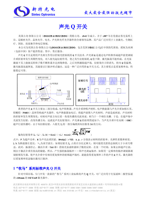
声光Q 开关是利用声光相互作用以控制光腔损耗的Q 开关技术。
声光调Q 是通过电声转换形成超声波使调制介质折射率发生周期性变化, 对入射光起衍射作用, 使之发生衍射损耗,Q 值下降, 激光振荡不能形成。
在光泵激励下其上能级反转粒子数不断积累并达到饱和值, 之后突然撤除超声场, 衍射效应立即消失, 腔内Q 值猛增, 激光振荡迅速恢复, 其能量以巨脉冲形式输出。
这是一种广泛应用的Q 开关方式,其主要优点是重复频率高,性能稳定可靠。
典型的声光Q 开关主要由三部分组成:电声转换器、声光介质和吸声材料。
电声换能器与声光介质如熔石英、钼酸铅(PbMO4)晶体等构成声光器件。
电声换能器加电后,将超声波馈入声光材料,声波是疏密波,声光材料的折射率发生周期变化,对相对声波方向以某一角度传播的光波来说,相当于一个相位光栅。
于是,在超声场中光波发生衍射,改变传播方向,这就是声光衍射效应。
声光调Q 的原理简述如下:当声光介质中有高频(40MC)超声行波传播时,由于布拉格衍射,入射光I i 的一部分偏离到布拉格角Id 的方向。
偏角衍射效率I d (L)/I i (0)=Sin2(ηL)=sin2()式中,P 为超声功率,M 为声光品质因素,M=n6p2/ρVS3. n,p,ρ分别表示材料的折射率,光弹性系数和密度。
专利名称:一种激光切割喷嘴体总成专利类型:实用新型专利
发明人:陈义红,陈义兵,易光纯
申请号:CN201821441323.4
申请日:20180904
公开号:CN208680786U
公开日:
20190402
专利内容由知识产权出版社提供
摘要:本实用新型公开了一种激光切割喷嘴体总成,包括上连接套、喷嘴座、喷嘴、氧气进气管和微调螺纹杆,所述喷嘴座顶部设有上连接套,所述喷嘴座底部安装喷嘴,所述上连接套内顶部开设激光束进口,所述上连接套与喷嘴座连接处设有与激光束进口连通的集气腔,所述集气腔位于激光束进口底部,所述集气腔一侧焊接氧气进气管,所述喷嘴内开设空腔,所述集气腔内底部连接喷嘴内层,所述喷嘴内层位于空腔内,所述喷嘴一侧焊接固定块,所述固定块内通过螺纹连接微调螺纹杆,所述微调螺纹杆一端通过旋转件连接喷嘴内层。
本实用新型激光切割喷嘴体总成,适合被广泛推广和使用。
申请人:武汉新特光电技术有限公司
地址:430000 湖北省武汉市东湖新技术开发区流芳园南路18号光电工业园产业大楼301室国籍:CN
代理机构:上海精晟知识产权代理有限公司
代理人:冯子玲
更多信息请下载全文后查看。
rev 1.04 / 2008 10 03QBU series Pockels cell driverUser ManualOverviewQBU series Pockels cell drivers produce high voltage pulses with highrepetition rates, fast risetimes and falltimes, adjustable voltage amplitude and pulse width.Pulse parametersModule produces bipolar output. It means that 4kV pulse is physically formed by applying +2kV to positive output wire and – 2kV to negativeAttention! Further description of HV output will be given in terms of voltage differences. Please keep it in mind!Typical pulse shapeRisetime/Falltime ~20 ns 1, 2Pulse width from 5 us to DC HV pulse amplitude from HVmin to HVmax 3Repetition ratesfrom single shot to ~10 kHz (continuously) 2, 4,to ~100 kHz (short-term) 2, 4Internal timing 5 ~100 us1at 10-90% level 2depends on HV pulse amplitude and capacity load 3HVmin and HVmax values see in part number table 4depends on working mode and cooling conditions 5see description belowInternal timingWithout Q-switch signal is applied driver maintains its state. Internal timer continuously refreshes driver condition every ~100us. It is cause of:1.HV output levels have small ripple with period ~100us2.It’s prohibited to trigger HV output level as internal timing is occurring.Therefore triggering of HV output is sometimes delayed. The delay timeis approx. 5usCooling At middle and high operation frequencies forced air cooling is required. The driver has internal protection from overheating – it automatically shuts down at~70CConnections, signals, signal descriptionsThere are three connectors at Pockels cell driver board. Hereafter isdescription of corresponded female connectors (supplied with the board)INTERFACE (Molex 39-30-1060):PIN (color)DESIGNATION DESCRIPTION1 (transparent ) Q-switchWhile “0” or ”1” is applied to PIN1 high voltage output is maintainedcorrespondingly at 0V or HV level Sequences of triggering pulses with period less than approx. 5 us are ignored by driver2 (violet ) Synchro OutBecause of internal timing a small delay of high voltage output triggering relative to Q-switch signal is possibleTherefore there is a synchronization pulse at PIN2 every time as the triggering of high voltage output is occurred. The synchro pulse is square, has negative polarity; back front synchronization 3 (red ) +15 VProvides +15V DC level 4 (blue ) EnableThe high voltage output is enabled by PIN4(“1” – enable, “0” – disable) 5, 6 (black)Interface ReturnPIN5 and PIN6 are connected to the circuit ground of all internal circuits7 (yellow ) HV MonitorThe voltage at PIN7 is a monitor signal proportional to the measured value of high voltage output HVmax corresponds to 10V at PIN7,HVmin corresponds to approx. 4V at PIN7 8 (green ) HV ProgramPositive DC voltage applied to PIN8 sets up high voltage value HVHVmax corresponds to 10V at PIN8,HVmin corresponds to approx. 4V at PIN8“0” means logical 0 low level (0V), “1” means logical 1 high level (5V)INTERFACE CIRCUITSQ-SwitchSynchro OutEnableHV Program and HV Monitor1k5PIN71022kPIN8A1BF+A1A1 : MC3307810k+24V (Molex 39-30-1040):+24VPIN (color)DESIGNATION DESCRIPTION1, 2 (red ) +24VINPUT positive 24VDC for turn on thePockels cell driver 3, 4 (black)RETURNReturn from power supply producing +24VDCHV OUTPUT (Molex 39-30-1060):HV OutputPIN (color)DESIGNATION DESCRIPTION1, 4 (red ) Positive HV Positive 2, 5N/C3, 6 (blue ) NegativeHV NegativeSafety Warning! This equipment produces high voltages that can be verydangerous. Don’t be careless around this equipment.•To provide safety the QBU-series Pockels cell driver module is designed to be powered with supply voltage +24VDC, which must be galvanically separated from mains.•It is the user’s responsibility to ensure that personnel are prevented from accidentally contacting the QBU-series Pockels cell driver module, especially the high voltageconnector and cable. Casual contact could be fatal. Output cables must have goodisolation for output voltage and low capacitance.•After shut down, do not touch the load until it has been discharged. Use an appropriate measurement device to check for complete discharge.•Disconnect the QBU-series Pockels cell driver module from DC power supply before changing electrical or mechanical connections.Operations1.Connect all wires2.Disable the high voltage output3.Apply the correct nominal DC Input power to the module4.Set up the required output voltage by applying a DC voltage to theHV Program PIN8 of INTERFACE5.Enable the high voltage output6.To start Pockels cell driver set driving pulses of necessaryrepetition rate to PIN1 of INTERFACE. Set pulse length not lessthan 5us7.To power down the QBU-series, remove DC Input power orDisable high voltage outputSpecification ELECTRICAL SPECIFICATIONInput+24V DC; 0,8A maxOutputRisetime/Falltime~20ns(depends on load)Pulse width from 5 us to DCHV pulse amplitude see Part number tableRepetition rate see Pulse parameters sectionCapacity load up to 500pFCooling forced airSafetyLeakage current not more then 150µAEnvironmentOperation Temperature-20 (45)Storage Temperature-40 (85)Humidity90%, non-condensingMECHANICAL SPECIFICATIONSize (LxWxH)130x80x25 mmWeight0,1 kgDRAWINGSPart number tablePart Number HVmax HVminQBU-5020 5000 2000QBU-4016 4000 1600QBU-3012 3000 1200QBU-2008 2000 800。