Simultaneous Absolute Timing of the Crab Pulsar at Radio and Optical Wavelengths
- 格式:pdf
- 大小:192.60 KB
- 文档页数:8

ONE、PLC overviewProgrammable controller is the first in the late 1960s in the United States, then called PLC programmable logic controller (Programmable Logic Controller) is used to replace relays. For the implementation of the logical judgment, timing, sequence number, and other control functions. The concept is presented PLC General Motors Corporation. PLC and the basic design is the computer functional improvements, flexible, generic and other advantages and relay control system simple and easy to operate, such as the advantages of cheap prices combined controller hardware is standard and overall. According to the practical application of target software in order to control the content of the user procedures memory controller, the controller and connecting the accused convenient target.In the mid-1970s, the PLC has been widely used as a central processing unit microprocessor, import export module and the external circuits are used, large-scale integrated circuits even when the PLC is no longer the only logical (IC) judgment functions also have data processing, PID conditioning and data communications functions. International Electro technical Commission (IEC) standards promulgated programmable controller for programmable controller draft made the following definition : programmable controller is a digital electronic computers operating system, specifically for applications in the industrial design environment. It used programmable memory, used to implement logic in their internal storage operations, sequence control, timing, counting and arithmetic operations, such as operating instructions, and through digital and analog input and output, the control of various types of machinery or production processes. Programmable controller and related peripherals, and industrial control systems easily linked to form a whole, to expand its functional design. Programmable controller for the user, is a non-contact equipment, the procedures can be changed to change production processes. The programmable controller has become a powerful tool for factory automation, widely popular replication. Programmable controller is user-oriented industries dedicatedcontrol computer, with many distinctive features.First, high reliability, anti-interference capability;Second programming visual, simple;Third, adaptability good;Fourth functional improvements, strong functional interface.TWO、History of PLCProgrammable Logic Controllers (PLC), a computing device invented by Richard E. Morley in 1968, have been widely used in industry including manufacturing systems, transportation systems, chemical process facilities, and many others. At that time, the PLC replaced the hardwired logic with soft-wired logic or so-called relay ladder logic (RLL), a programming language visually resembling the hardwired logic, and reduced thereby the configuration time from 6 months down to 6 days [Moody and Morley, 1999].Although PC based control has started to come into place, PLC based control will remain the technique to which the majority of industrial applications will adhere due to its higher performance, lower price, and superior reliability in harsh environments. Moreover, according to a study on the PLC market of Frost and Sullivan [1995], an increase of the annual sales volume to 15 million PLCs per year with the hardware value of more than 8 billion US dollars has been predicted, though the prices of computing hardware is steadily dropping. The inventor of the PLC, Richard E Morley, fairly considers the PLC market as a 5-billion industry at the present time.Though PLCs are widely used in industrial practice, the programming of PLC based control systems is still very much relying on trial-and-error. Alike software engineering, PLC software design is facing the software dilemma or crisis in a similar way. Morley himself emphasized this aspect most forcefully by indicating `If houses were built like software projects, a single woodpecker could destroy civilization.”Particularly, practical problems in PLC programming are to eliminate software bugs and to reduce the maintenance costs of old ladder logic programs. Thoughthe hardware costs of PLCs are dropping continuously, reducing the scan time of the ladder logic is still an issue in industry so that low-cost PLCs can be used.In general, the productivity in generating PLC is far behind compared to other domains, for instance, VLSI design, where efficient computer aided design tools are in practice. Existent software engineering methodologies are not necessarily applicable to the PLC based software design because PLC-programming requires a simultaneous consideration of hardware and software. The software design becomes, thereby, more and more the major cost driver. In many industrial design projects, more than of the manpower allocated for the control system design and installation is scheduled for testing and debugging PLC programs.In addition, current PLC based control systems are not properly designed to support the growing demand for flexibility and reconfigurability of manufacturing systems. A further problem, impelling the need for a systematic design methodology, is the increasing software complexity in large-scale projects.The objective of this thesis is to develop a systematic software design methodology for PLC operated automation systems. The design methodology involves high-level description based on state transition models that treat automation control systems as discrete event systems, a stepwise design process, and set of design rules providing guidance and measurements to achieve a successful design. The tangible outcome of this research is to find a way to reduce the uncertainty in managing the control software development process, that is, reducing programming and debugging time and their variation, increasing flexibility of the automation systems, and enabling software reusability through modularity. The goal is to overcome shortcomings of current programming strategies that are based on the experience of the individual software developer.Three、now of PLCFrom the structure is divided into fixed PLC and Module PLC, the two kinds of PLC including CPU board, I/O board, display panel, memory block, power, these elements into a do not remove overall. Module type PLC including CPU module,I/O modules, memory, the power modules, bottom or a frame, these modules can be according to certain rules combination configuration.In the user view, a detailed analysis of the CPU's internal unnecessary, but working mechanism of every part of the circuit. The CPU control works, by it reads CPU instruction, interprets the instruction and executes instructions. But the pace of work by shock signal control.Unit work under the controller command used in a digital or logic operation.In computing and storage register of computation result, it is also among the controller command and work. CPU speed and memory capacity is the important parameters for PLC , its determines the PLC speed of work, IO PLC number and software capacity, so limits to control size.Central Processing Unit (CPU) is the brain of a PLC controller. CPU itself is usually one of the microcontrollers. Aforetime these were 8-bit microcontrollers such as 8051, and now these are 16-and 32-bit microcontrollers. Unspoken rule is that you‟ll find mostly Hitachi and Fujicu microcontrollers in PLC controllers by Japanese makers, Siemens in European controllers, and Motorola microcontrollers in American ones. CPU also takes care of communication, interconnectedness among other parts of PLC controllers, program execution, memory operation, overseeing input and setting up of an output.System memory (today mostly implemented in FLASH technology) is used by a PLC for a process control system. Aside form. this operating system it also contains a user program translated forma ladder diagram to a binary form. FLASH memory contents can be changed only in case where user program is being changed. PLC controllers were used earlier instead of PLASH memory and have had EPROM memory instead of FLASH memory which had to be erased with UV lamp and programmed on programmers. With the use of FLASH technology this process was greatly shortened. Reprogramming a program memory is done through a serial cable in a program for application development.User memory is divided into blocks having special functions. Some parts of amemory are used for storing input and output status. The real status of an input is stored either as “1”or as “0”in a specific memory bit/ each input or output has one corresponding bit in memory. Other parts of memory are used to store variable contents for variables used in used program. For example, time value, or counter value would be stored in this part of the memory.PLC controller can be reprogrammed through a computer (usual way), but also through manual programmers (consoles). This practically means that each PLC controller can programmed through a computer if you have the software needed for programming. Today‟s transmission computers are ideal for reprogramming a PLC controller in factory itself. This is of great importance to industry. Once the system is corrected, it is also important to read the right program into a PLC again. It is also good to check from time to time whether program in a PLC has not changed. This helps to avoid hazardous situations in factory rooms (some automakers have established communication networks which regularly check programs in PLC controllers to ensure execution only of good programs). Almost every program for programming a PLC controller possesses various useful options such as: forced switching on and off of the system input/outputs (I/O lines), program follow up in real time as well as documenting a diagram. This documenting is necessary to understand and define failures and malfunctions. Programmer can add remarks, names of input or output devices, and comments that can be useful when finding errors, or with system maintenance. Adding comments and remarks enables any technician (and not just a person who developed the system) to understand a ladder diagram right away. Comments and remarks can even quote precisely part numbers if replacements would be needed. This would speed up a repair of any problems that come up due to bad parts. The old way was such that a person who developed a system had protection on the program, so nobody aside from this person could understand how it was done. Correctly documented ladder diagram allows any technician to understand thoroughly how system functions.Electrical supply is used in bringing electrical energy to central processing unit.Most PLC controllers work either at 24 VDC or 220 VAC. On some PLC controllers you‟ll find electrical supply as a separate module. Those are usually bigger PLC controllers, while small and medium series already contain the supply module. User has to determine how much current to take from I/O module to ensure that electrical supply provides appropriate amount of current. Different types of modules use different amounts of electrical current.This electrical supply is usually not used to start external input or output. User has to provide separate supplies in starting PLC controller inputs because then you can ensure so called “pure”supply for the PLC controller. With pure supply we mean supply where industrial environment can not affect it damagingly. Some of the smaller PLC controllers supply their inputs with voltage from a small supply source already incorporated into a PLC.Four、PLC design criteriaA systematic approach to designing PLC software can overcome deficiencies in the traditional way of programming manufacturing control systems, and can have wide ramifications in several industrial applications. Automation control systems are modeled by formal languages or, equivalently, by state machines. Formal representations provide a high-level description of the behavior of the system to be controlled. State machines can be analytically evaluated as to whether or not they meet the desired goals. Secondly, a state machine description provides a structured representation to convey the logical requirements and constraints such as detailed safety rules. Thirdly, well-defined control systems design outcomes are conducive to automatic code generation-An ability to produce control software executable on commercial distinct logic controllers can reduce programming lead-time and labor cost. In particular, the thesis is relevant with respect to the following aspects.In modern manufacturing, systems are characterized by product and process innovation, become customer-driven and thus have to respond quickly to changing system requirements. A major challenge is therefore to provide enabling technologies that can economically reconfigure automation controlsystems in response to changing needs and new opportunities. Design and operational knowledge can be reused in real-time, therefore, giving a significant competitive edge in industrial practice.Studies have shown that programming methodologies in automation systems have not been able to match rapid increase in use of computing resources. For instance, the programming of PLCs still relies on a conventional programming style with ladder logic diagrams. As a result, the delays and resources in programming are a major stumbling stone for the progress of manufacturing industry. Testing and debugging may consume over 50% of the manpower allocated for the PLC program design. Standards [IEC 60848, 1999; IEC-61131-3, 1993; IEC 61499, 1998; ISO 15745-1, 1999] have been formed to fix and disseminate state-of-the-art design methods, but they normally cannot participate in advancing the knowledge of efficient program and system design.A systematic approach will increase the level of design automation through reusing existing software components, and will provide methods to make large-scale system design manageable. Likewise, it will improve software quality and reliability and will be relevant to systems high security standards, especially those having hazardous impact on the environment such as airport control, and public railroads.The software industry is regarded as a performance destructor and complexity generator. Steadily shrinking hardware prices spoils the need for software performance in terms of code optimization and efficiency. The result is that massive and less efficient software code on one hand outpaces the gains in hardware performance on the other hand. Secondly, software proliferates into complexity of unmanageable dimensions; software redesign and maintenance-essential in modern automation systems-becomes nearly impossible. Particularly, PLC programs have evolved from a couple lines of code 25 years ago to thousands of lines of code with a similar number of 1/O points. Increased safety, for instance new policies on fire protection, and the flexibility of modern automation systems add complexity to the program design process.Consequently, the life-cycle cost of software is a permanently growing fraction of the total cost. 80-90% of these costs are going into software maintenance, debugging, adaptation and expansion to meet changing needs.Today, the primary focus of most design research is based on mechanical or electrical products. One of the by-products of this proposed research is to enhance our fundamental understanding of design theory and methodology by extending it to the field of engineering systems design. A system design theory for large-scale and complex system is not yet fully developed. Particularly, the question of how to simplify a complicated or complex design task has not been tackled in a scientific way. Furthermore, building a bridge between design theory and the latest epistemological outcomes of formal representations in computer sciences and operations research, such as discrete event system modeling, can advance future development in engineering design.From a logical perspective, PLC software design is similar to the hardware design of integrated circuits. Modern VLSI designs are extremely complex with several million parts and a product development time of 3 years [Whitney, 1996]. The design process is normally separated into a component design and a system design stage. At component design stage, single functions are designed and verified. At system design stage, components are aggregated and the whole system behavior and functionality is tested through simulation. In general, a complete verification is impossible. Hence, a systematic approach as exemplified for the PLC program design may impact the logical hardware design.Five、AK 1703 ACPFollowing the principle of our product development, AK 1703 ACP has high functionality and flexibility, through the implementation of innovative and reliable technologies, on the stable basis of a reliable product platform.For this, the system concept ACP (Automation, Control and Protection) creates the technological preconditions. Balanced functionality permits the flexible combination of automation, telecontrol and communication tasks. Complemented with the scalable performance and various redundancyconfigurations, an optimal adaptation to the respective requirements of the process is achieved.AK 1703 ACP is thus perfectly suitable for automation with integrated telecontrol technology as:•Telecontrol substation or central device•Automation unit with autonomous functional groups•Data node, station control device, front-end or gateway•With local or remote peripherals•For rear panel installation or 19 inch assembly•Branch-neutral product, therefore versatile fields of application and high productstability•Versatile communication•Easy engineering•Plug & play for spare parts•Open system architecture•Scalable redundancy•The intelligent terminal - TM 1703The Base Unit AK 1703 ACP with Peripheral Elements has one basic system element CP-2010/CPC25 (Master control element) and CP-2012/PCCE25 (Processing and communication element) ,one bus line with max. 16 peripheral elements can be connected.CP-2010/CPC25 Features and FunctionsSystem Functions:•Central element,coordinating all system servicesCentral hub function for all connected basic system elements•Time managementCentral clock of the automation unitSetting and keeping the own clock`s time with a resolution of 10ms Synchronization via serid communication via LAN or local•RedundancyVoting and change-over for redundant processing and communication elements of the own automation unitSupports voting and change-over by an external SCA-RS redundancy switch Supports applicational voting and change-over by an external system,e.g.a control system•SAT TOLLBOX|| connectionStoring firmware and parameters on a Flash CardCommunication:•Communication via installable protocol elements to any superior or subordinate automation unit•Automatic data flow routing•Priority based data transmission (priority control)•Own circular buffer and process image for each connected station(data keeping)•Redundant communication routesCommunication with redundant remote stations•Special application specific functions for dial-up trafficTest if stations are reachableProcess Peripherals:•Transmission of spontaneous information objects from and to peripheral elements, via the serial Ax 1703 peripheral busFunctions for Automation:•Open-/closed-loop control function for the execution of freely definable user programs which are created with CAEX plus according to IEC 61131-3,ing function diagram technology 512KB for user programApprox 50.000 variables and signals,2.000 of them retainedCycle of 10ms or a multiple thereofOnline testLoadable without service interruption•Redundant open-/closed-loop control functionsSynchronization via redundancy linkTransmission of periodic process information between the open-/closed-loop control function and the peripheral elements,via the serial Ax 1703 peripheral bus.Six、SIEMENS PLCSIMATIC S7-300 series PLC applied to all walks of life and various occasions in the detection, monitoring and control of automation, its power to both the independent operation of, or connected to a network able to achieve complex control.The photoelectric products with isolation, high electromagnetic compatibility; have high industrial applicability, allowing the ambient temperature of 60 ℃; has strong anti-jamming and anti-vibration and impact resistance, so in a harsh working environment has been widely Applications.I also mean freedom of communication S7-300 type PLC' s a very unique feature, which allows S7-300-PLC can deal openly with any other communications equipment, communications controller, or PLC S7-300 type can be defined by the user's own Communications protocol (of the agreement ASCII), the baud rate to 1.5 Mbit / s (adjustable). So that can greatly increase the scope of communications so that the control system configuration more flexible and convenient. Of any kind with a serial interface peripherals, such as: printers or bar code readers, Drives, a modem (Modem), the top PC-connected, and so can be used. Users can program to develop communication protocols, the exchange of data (for example: ASCII character code), RS232 interfaces with the equipment can also be used PC / PPI cable linking the free communication communications. When the PC offline, under the control of the next crew, the whole system can operate normally.PC that is by control centre, mainly by the PC and laser printer components, using SIMATIC WINCC software platform, the all-Chinese interface, friendly man-machine dialogue. Managers and operators can be observed through a PC,shown in the various kinds of information to understand the present and pion tasks.WINCC and the ice-storage operation of the automatic control system and all the parameters, and through the mouse to print equipment management and implement at software in the field of automation can be used for all the operators‟control and monitoring tasks. Can be controlled in the process of the events clearly show, and shows the current status and order records, the recorded data can show all or select summary form, or may be required for editing, printing and output statements and trends .WINCC able to control the critical situation in the early stages of the report, and the signal can be displayed on the screen, can also use sound to be felt. It supported by online help and operational guidelines to eliminate failure. WINCC a workstation can be devoted to the process control to the process so that important information not is shielded. Software-assisted operation strategy ensures that the process was not illegal to visit and to provide for non-industrial environment in the wrong operation.WINCC is MICRSOFT WINDOWS98 or WINDOWS NT4.0 operating system,running on a PC object-oriented class 32-bit applications, OLE through the window and ODBC standard mechanism, as an ideal partner to enter the communications world WINDOWS, it can be easily WINCC To integrate a company-wide data processing system.Seven、CommunicationsCommunications are vital to an individual automation cell and to the automated factory as a whole. We've heard a lot about MAP in the last few years, and a lot of companies have jumped on the band wagon. Many, however were disappointed when a fully-defined and completed MAP specification didn’t appear immediately. Says Larry Kumara:”Right now , MAP is still a moving target for the manufacturers specification that is not final. Presently, for example, people are introducing products to meet the MAP 2.1standard.Yet 2.1-basedproducts will be obsolete when the new standard for MAP,3.0 is introduced.”Because of this, many PLC vendors are holding off on full MAP implementations. Omron, for example has an ongoing MAP-compatibility program, but Frank Newborn, vice president of Omron‟s Industrial Division, reports that because of the lack of a firm definition, Omron's PLCs don't yet talk to MAP.Since it‟s unlikely that an individual PLC would talk to broadband MAP anyway, makers are concentrating n proprietary networks. According to Sal Provanzano, users fear that if they do get on board and vendors withdraw from MAP, they’ll pulse width modulation control system be the ones left holding a communications structure that‟s not supported.。
BurrĆBrown Productsfrom TexasInstrumentsFEATURES DESCRIPTIONAPPLICATIONSA GND FA GND DI OUT DR FB DA GND CI OUT CR FB CA GND BI OUT CR FB BA GND AI OUT AR FB ADAC8814SBAS338D–JANUARY2005–REVISED SEPTEMBER2006 Quad,Serial Input16-Bit Multiplying Digital-to-Analog Converter•Relative Accuracy:1LSB Max The DAC8814is a quad,16-bit,current-output •Differential Nonlinearity:1LSB Max digital-to-analog converter(DAC)designed tooperate from a single+2.7-V to5.0-V supply.•2-mA Full-Scale Currentwith V REF=±10V The applied external reference input voltage VREF •0.5-µs Settling Time determines the full-scale output current.An internalfeedback resistor(R FB)provides temperature •Midscale or Zero-Scale Resettracking for the full-scale output when combined with •Four Separate4Q Multiplying Referencean external I-to-V precision amplifier.InputsA doubled buffered serial data interface offers •Reference Bandwidth:10MHzhigh-speed,3-wire,SPI and microcontroller •Reference Dynamics:–105dB THDcompatible inputs using serial data in(SDI),clock •SPI™-Compatible3-Wire Interface:(CLK),and a chip-select(CS).In addition,a serial 50MHz data out pin(SDO)allows for daisy-chaining when •Double Buffered Registers Enable multiple packages are used.A commonlevel-sensitive load DAC strobe(LDAC)input allows •Simultaneous Multichannel Changesimultaneous update of all DAC outputs from •Internal Power-On Resetpreviously loaded input registers.Additionally,an •Industry-Standard Pin Configuration internal power-on reset forces the output voltage tozero at system turn on.An MSB pin allows systemreset assertion(RS)to force all registers to zerocode when MSB=0,or to half-scale code when •Automatic Test EquipmentMSB=1.•Instrumentation•Digitally-Controlled Calibration The DAC8814is available in an SSOP package.Please be aware that an important notice concerning availability,standard warranty,and use in critical applications of TexasInstruments semiconductor products and disclaimers thereto appears at the end of this data sheet.SPI is a trademark of Motorola,Inc.All other trademarks are the property of their respective owners.PRODUCTION DATA information is current as of publication date.Copyright©2005–2006,Texas Instruments Incorporated Products conform to specifications per the terms of the TexasInstruments standard warranty.Production processing does notnecessarily include testing of all parameters.ABSOLUTE MAXIMUM RATINGS (1)DAC8814SBAS338D–JANUARY 2005–REVISED SEPTEMBER 2006This integrated circuit can be damaged by ESD.Texas Instruments recommends that all integrated circuits be handled with appropriate precautions.Failure to observe proper handling and installation procedures can cause damage.ESD damage can range from subtle performance degradation to complete device failure.Precision integrated circuits may be more susceptible to damage because very small parametric changes could cause the device not to meet its published specifications.PACKAGE/ORDERING INFORMATION (1)MINIMUM RELATIVE DIFFERENTIAL SPECIFIED TRANSPORT ACCURACYNONLINEARITYTEMPERATUREPACKAGE-PACKAGE ORDERING MEDIA,PRODUCT (LSB)(LSB)RANGE LEAD DESIGNATORNUMBER QUANTITY DAC8814ICDBT Tape and Reel,250DAC8814C ±1±1–40°C to +85°C SSOP-28DB DAC8814ICDBR Tape and Reel,2500DAC8814IBDBT Tape and Reel,250DAC8814B±4±1.5–40°C to +85°CSSOP-28DBDAC8814IBDBRTape and Reel,2500(1)For the most current specifications and package information,see the Package Option Addendum located at the end of this document,or see the TI website at .DAC8814UNIT V DD to GND –0.3to +8V V REF to GND–18to +18V Logic inputs and output to GND –0.3to +8V V(I OUT )to GND –0.3to V DD +0.3V A GND X to DGND–0.3to +0.3V Input current to any pin except supplies ±50mA Package power dissipation (T J max –T A )/θJAW Thermal resistance,θJA28-Lead shrink surface-mount (RS-28)100°C/W Maximum junction temperature (T J max)150°C Operating temperature range,Model A –40to +85°C Storage temperature range –65to +150°C ESD rating,HBM 3000V ESD rating,CDM 500V(1)Stresses above those listed under absolute maximum ratings may cause permanent damage to the device.This is a stress rating only;functional operation of the device at these or any other conditions above those indicated in the operational sections of this specification is not implied.Exposure to absolute maximum conditions for extended periods may affect device reliability.2Submit Documentation FeedbackELECTRICAL CHARACTERISTICSDAC8814 SBAS338D–JANUARY2005–REVISED SEPTEMBER2006V DD =2.7V to5.5V;IOUTX=Virtual GND,AGNDX=0V,VREFA,B,C,D=10V,TA=full operating temperature range,unlessotherwise noted.DAC8814 PARAMETER SYMBOL CONDITIONS MIN TYP MAX UNIT STATIC PERFORMANCE(1)Resolution16Bits Relative accuracy INL DAC8814B±4LSBINL DAC8814C±1LSB Differential nonlinearity DNL DAC8814B±1.5LSBDNL DAC8814C±1LSB Output leakage current I OUT X Data=0000h,T A=25°C10nAI OUT X Data=0000h,T A=T A max20nAFull-scale gain error G FSE Data=FFFFh±0.75±3mVFull-scale tempco(2)TCV FS1ppm/°C Feedback resistor R FB X V DD=5V5kΩREFERENCE INPUTV REF X Range V REF X–1515VInput resistance R REF X456kΩInput resistance match R REF X Channel-to-channel1% Input capacitance(2)C REF X5pF ANALOG OUTPUTOutput current I OUT X Data=FFFFh 1.6 2.5mA Output capacitance(2)C OUT X Code-dependent50pF LOGIC INPUTS AND OUTPUTInput low voltage V IL V DD=+2.7V0.6VV IL V DD=+5V0.8VInput high voltage V IH V DD=+2.7V 2.1VV IH V DD=+5V 2.4VInput leakage current I IL1µA Input capacitance(2)C IL10pF Logic output low voltage V OL I OL=1.6mA0.4V Logic output high voltage V OH I OH=100µA4V INTERFACE TIMING(2),(3)Clock input frequency f CLK50MHz Clock width high t CH10ns Clock width low t CL10nsCS to Clock setup t CSS0ns Clock to CS hold t CSH10ns Clock to SDO prop delay t PD220ns Load DAC pulsewidth t LDAC25ns Data setup t DS5ns Data hold t DH10ns Load setup t LDS5ns Load hold t LDH10ns (1)All static performance tests(except I OUT)are performed in a closed-loop system using an external precision OPA277I-to-V converteramplifier.The DAC8814R FB terminal is tied to the amplifier output.Typical values represent average readings measured at+25°C.(2)These parameters are specified by design and not subject to production testing.(3)All input control signals are specified with t R=t F=2.5ns(10%to90%of3V)and timed from a voltage level of1.5V.3Submit Documentation FeedbackDAC8814SBAS338D–JANUARY 2005–REVISED SEPTEMBER 2006ELECTRICAL CHARACTERISTICS (continued)V DD =2.7V to 5.5V;I OUT X =Virtual GND,A GND X =0V,V REF A,B,C,D =10V,T A =full operating temperature range,unless otherwise noted.DAC8814PARAMETERSYMBOL CONDITIONS MIN TYP MAX UNIT SUPPLY CHARACTERISTICS Power supply range V DDRANGE2.75.5V Logic inputs =0V,Positive supply currentI DD 25µA V DD =+4.5V to +5.5V Logic inputs =0V,I DD12.5µA V DD =+2.7V to +3.6V Power dissipation P DISS Logic inputs =0V 0.0275mW Power supply sensitivity P SS∆V DD =±5%0.006%AC CHARACTERISTICS (4)To ±0.1%of full-scale,Output voltage settling timet s 0.3µs Data =0000h to FFFFh to 0000h To ±0.0015%of full-scale,t s0.5µs Data =0000h to FFFFh to 0000hReference multiplying BW BW –3dBV REF X =100mV RMS ,Data =FFFFh,C FB =3pF 10MHz DAC glitch impulse QV REF X =10V,Data =7FFFh to 8000h to 7FFFh 5nV-s Feedthrough error V OUT X/V REF X Data =0000h,V REF X =100mV RMS ,f =100kHz–70dB Data =0000h,V REF B =100mV RMS ,Crosstalk error V OUT A/V REF B–100dB Adjacent channel,f =100kHzDigital feedthrough Q CS =1and f CLK =1MHz1nV-s Total harmonic distortion THD V REF =5V PP ,Data =FFFFh,f =1kHz–105dB Output spot noise voltage e nf =1kHz,BW =1Hz12nV/√Hz(4)All ac characteristic tests are performed in a closed-loop system using a THS4011I-to-V converter amplifier.4Submit Documentation FeedbackPIN CONFIGURATIONSA GND I OUT V REF R FB RS V DD CS R FB V REF I OUT A GND A GND D I OUT D V REF D R FB D DGND V SS (1)A GND F LDAC SDO NC (1)R FB C V REF C I OUT C A GND CDB Package (TOP VIEW)NOTE (1): No internal connectionDAC8814SBAS338D–JANUARY 2005–REVISED SEPTEMBER 2006PIN DESCRIPTION5Submit Documentation FeedbackTYPICAL CHARACTERISTICS:V DD =+5VChannel A819216384245763276840960491525734465535D N L (L S B )Digital Input Code1.00.80.60.40.20−0.2−0.4−0.6−0.8−1.0819216384245763276840960491525734465535I N L (L S B )Digital Input Code1.00.80.60.40.20−0.2−0.4−0.6−0.8−1.0819216384245763276840960491525734465535I N L (L S B )Digital Input Code1.00.80.60.40.20−0.2−0.4−0.6−0.8−1.0819216384245763276840960491525734465535D N L (L S B )Digital InputCode1.00.80.60.40.20−0.2−0.4−0.6−0.8−1.0819216384245763276840960491525734465535D N L (L S B )Digital Input Code1.00.80.60.40.20−0.2−0.4−0.6−0.8−1.0819216384245763276840960491525734465535I N L (L S B )Digital Input Code1.00.80.60.40.20−0.2−0.4−0.6−0.8−1.0DAC8814SBAS338D–JANUARY 2005–REVISED SEPTEMBER 2006At T A =+25°C,+V DD =+5V,unless otherwise noted.LINEARITY ERROR DIFFERENTIAL LINEARITY ERRORvs DIGITAL INPUT CODEvs DIGITAL INPUT CODEFigure 1.Figure 2.LINEARITY ERROR DIFFERENTIAL LINEARITY ERRORvs DIGITAL INPUT CODEvs DIGITAL INPUT CODEFigure 3.Figure 4.LINEARITY ERROR DIFFERENTIAL LINEARITY ERRORvs DIGITAL INPUT CODEvs DIGITAL INPUT CODEFigure 5.Figure 6.6Submit Documentation FeedbackChannel B819216384245763276840960491525734465535I N L (L S B )Digital InputCode1.00.80.60.40.20−0.2−0.4−0.6−0.8−1.0819216384245763276840960491525734465535D N L (L S B )Digital InputCode1.00.80.60.40.20−0.2−0.4−0.6−0.8−1.0819216384245763276840960491525734465535I N L (L S B )Digital InputCode1.00.80.60.40.20−0.2−0.4−0.6−0.8−1.0819216384245763276840960491525734465535D N L (L S B )Digital InputCode1.00.80.60.40.20−0.2−0.4−0.6−0.8−1.0819216384245763276840960491525734465535I N L (L S B )Digital InputCode1.00.80.60.40.20−0.2−0.4−0.6−0.8−1.0819216384245763276840960491525734465535D N L (L S B )Digital InputCode1.00.80.60.40.20−0.2−0.4−0.6−0.8−1.0DAC8814SBAS338D–JANUARY 2005–REVISED SEPTEMBER 2006TYPICAL CHARACTERISTICS:V DD =+5V (continued)At T A =+25°C,+V DD =+5V,unless otherwise noted.LINEARITY ERROR DIFFERENTIAL LINEARITY ERRORvs DIGITAL INPUT CODEvs DIGITAL INPUT CODEFigure 7.Figure 8.LINEARITY ERROR DIFFERENTIAL LINEARITY ERRORvs DIGITAL INPUT CODEvs DIGITAL INPUT CODEFigure 9.Figure 10.LINEARITY ERROR DIFFERENTIAL LINEARITY ERRORvs DIGITAL INPUT CODEvs DIGITAL INPUT CODEFigure 11.Figure 12.7Submit Documentation FeedbackChannel C1.00.80.60.40.20−0.2−0.4−0.6−0.8−1.0819216384245763276840960491525734465535I N L (L S B )Digital Input Code819216384245763276840960491525734465535D N L (L S B )Digital Input Code1.00.80.60.40.20−0.2−0.4−0.6−0.8−1.0819216384245763276840960491525734465535I N L (L S B )Digital InputCode1.00.80.60.40.20−0.2−0.4−0.6−0.8−1.0819216384245763276840960491525734465535D N L (L S B )Digital Input Code1.00.80.60.40.20−0.2−0.4−0.6−0.8−1.0819216384245763276840960491525734465535I N L (L S B )Digital Input Code1.00.80.60.40.20−0.2−0.4−0.6−0.8−1.0819216384245763276840960491525734465535D N L (L S B )Digital Input Code1.00.80.60.40.20−0.2−0.4−0.6−0.8−1.0DAC8814SBAS338D–JANUARY 2005–REVISED SEPTEMBER 2006TYPICAL CHARACTERISTICS:V DD =+5V (continued)At T A =+25°C,+V DD =+5V,unless otherwise noted.LINEARITY ERROR DIFFERENTIAL LINEARITY ERRORvs DIGITAL INPUT CODEvs DIGITAL INPUT CODEFigure 13.Figure 14.LINEARITY ERROR DIFFERENTIAL LINEARITY ERRORvs DIGITAL INPUT CODEvs DIGITAL INPUT CODEFigure 15.Figure 16.LINEARITY ERROR DIFFERENTIAL LINEARITY ERRORvs DIGITAL INPUT CODEvs DIGITAL INPUT CODEFigure 17.Figure 18.8Submit Documentation FeedbackChannel D819216384245763276840960491525734465535I N L (L S B )Digital Input Code1.00.80.60.40.20−0.2−0.4−0.6−0.8−1.0819216384245763276840960491525734465535D N L (L S B )Digital Input Code1.00.80.60.40.20−0.2−0.4−0.6−0.8−1.0819216384245763276840960491525734465535I N L (L S B )Digital InputCode1.00.80.60.40.20−0.2−0.4−0.6−0.8−1.0819216384245763276840960491525734465535D N L (L S B )Digital InputCode1.00.80.60.40.20−0.2−0.4−0.6−0.8−1.0819216384245763276840960491525734465535I N L (L S B )Digital Input Code1.00.80.60.40.20−0.2−0.4−0.6−0.8−1.0819216384245763276840960491525734465535D N L (L S B )Digital Input Code1.00.80.60.40.20−0.2−0.4−0.6−0.8−1.0DAC8814SBAS338D–JANUARY 2005–REVISED SEPTEMBER 2006TYPICAL CHARACTERISTICS:V DD =+5V (continued)At T A =+25°C,+V DD =+5V,unless otherwise noted.LINEARITY ERROR DIFFERENTIAL LINEARITY ERRORvs DIGITAL INPUT CODEvs DIGITAL INPUT CODEFigure 19.Figure 20.LINEARITY ERROR DIFFERENTIAL LINEARITY ERRORvs DIGITAL INPUT CODEvs DIGITAL INPUT CODEFigure 21.Figure 22.LINEARITY ERROR DIFFERENTIAL LINEARITY ERRORvs DIGITAL INPUT CODEvs DIGITAL INPUT CODEFigure 23.Figure 24.9Submit Documentation Feedback18016014012010080604020000.51.01.52.02.53.03.54.04.55.0S u p p l y C u r r e n t ,I D D (µA )Logic Input Voltage (V)−−−−−−−−−−−−−−−−−−A Digital Codet t e n u a t i o n (d B )B andw idth (H z)Time (0.2µs/div)O u t p u t V o l t a g e (50m V /d i v )Time (0.1µs/div)O u t p u t V o l t a g e (5V /d i v )3210−1−2−3−40−20100E n d p o i n t E r r o r (m V )Temperature (_C)204060805.04.54.03.53.02.52.01.51.00.50Temperature (_C)−2020I D D (µA )5.0V2.7V 406080100−40DAC8814SBAS338D–JANUARY 2005–REVISED SEPTEMBER 2006TYPICAL CHARACTERISTICS:V DD =+5V (continued)At T A =+25°C,+V DD =+5V,unless otherwise noted.SUPPLY CURRENT vs LOGIC INPUT VOLTAGEREFERENCE MULTIPLYING BANDWIDTHFigure 25.Figure 26.DAC GLITCHDAC SETTLING TIMEFigure 27.Figure 28.I DD vs TEMPERATUREENDPOINT ERROR vs TEMPERATUREFigure 29.Figure 30.10Submit Documentation FeedbackTYPICAL CHARACTERISTICS:V DD =+2.7VChannel A819216384245763276840960491525734465535I N L (L S B )Digital Input Code1.00.80.60.40.20−0.2−0.4−0.6−0.8−1.0819216384245763276840960491525734465535D N L (L S B )Digital Input Code1.00.80.60.40.20−0.2−0.4−0.6−0.8−1.0819216384245763276840960491525734465535I N L (L S B )Digital InputCode1.00.80.60.40.20−0.2−0.4−0.6−0.8−1.0819216384245763276840960491525734465535D N L (L S B )Digital InputCode1.00.80.60.40.20−0.2−0.4−0.6−0.8−1.0819216384245763276840960491525734465535I N L (L S B )Digital Input Code1.00.80.60.40.20−0.2−0.4−0.6−0.8−1.0819216384245763276840960491525734465535D N L (L S B )Digital Input Code1.00.80.60.40.20−0.2−0.4−0.6−0.8−1.0At T A =+25°C,+V DD =+2.7V,unless otherwise noted.LINEARITY ERROR DIFFERENTIAL LINEARITY ERRORvs DIGITAL INPUT CODEvs DIGITAL INPUT CODEFigure 31.Figure 32.LINEARITY ERROR DIFFERENTIAL LINEARITY ERRORvs DIGITAL INPUT CODEvs DIGITAL INPUT CODEFigure 33.Figure 34.LINEARITY ERROR DIFFERENTIAL LINEARITY ERRORvs DIGITAL INPUT CODEvs DIGITAL INPUT CODEFigure 35.Figure 36.Channel B819216384245763276840960491525734465535D N L (L S B )Digital InputCode1.00.80.60.40.20−0.2−0.4−0.6−0.8−1.01.00.80.60.40.20−0.2−0.4−0.6−0.8−1.0819216384245763276840960491525734465535I N L (L S B )Digital Input Code819216384245763276840960491525734465535I N L (L S B )Digital InputCode 1.00.80.60.40.20−0.2−0.4−0.6−0.8−1.0819216384245763276840960491525734465535D N L (L S B )Digital Input Code1.00.80.60.40.20−0.2−0.4−0.6−0.8−1.0819216384245763276840960491525734465535I N L (L S B )Digital InputCode1.00.80.60.40.20−0.2−0.4−0.6−0.8−1.0819216384245763276840960491525734465535D N L (L S B )Digital Input Code1.00.80.60.40.20−0.2−0.4−0.6−0.8−1.0DD At T A =+25°C,+V DD =+2.7V,unless otherwise noted.LINEARITY ERROR DIFFERENTIAL LINEARITY ERRORvs DIGITAL INPUT CODEvs DIGITAL INPUT CODEFigure 37.Figure 38.LINEARITY ERROR DIFFERENTIAL LINEARITY ERRORvs DIGITAL INPUT CODEvs DIGITAL INPUT CODEFigure 39.Figure 40.LINEARITY ERROR DIFFERENTIAL LINEARITY ERRORvs DIGITAL INPUT CODEvs DIGITAL INPUT CODEFigure 41.Figure 42.Channel C819216384245763276840960491525734465535I N L (L S B )Digital Input Code1.00.80.60.40.20−0.2−0.4−0.6−0.8−1.0819216384245763276840960491525734465535D N L (L S B )Digital Input Code1.00.80.60.40.20−0.2−0.4−0.6−0.8−1.0819216384245763276840960491525734465535I N L (L S B )Digital InputCode1.00.80.60.40.20−0.2−0.4−0.6−0.8−1.0819216384245763276840960491525734465535D N L (L S B )Digital InputCode1.00.80.60.40.20−0.2−0.4−0.6−0.8−1.0819216384245763276840960491525734465535I N L (L S B )Digital Input Code1.00.80.60.40.20−0.2−0.4−0.6−0.8−1.0819216384245763276840960491525734465535D N L (L S B )Digital Input Code1.00.80.60.40.20−0.2−0.4−0.6−0.8−1.0DD At T A =+25°C,+V DD =+2.7V,unless otherwise noted.LINEARITY ERROR DIFFERENTIAL LINEARITY ERRORvs DIGITAL INPUT CODEvs DIGITAL INPUT CODEFigure 43.Figure 44.LINEARITY ERROR DIFFERENTIAL LINEARITY ERRORvs DIGITAL INPUT CODEvs DIGITAL INPUT CODEFigure 45.Figure 46.LINEARITY ERROR DIFFERENTIAL LINEARITY ERRORvs DIGITAL INPUT CODEvs DIGITAL INPUT CODEFigure 47.Figure 48.Channel D819216384245763276840960491525734465535I N L (L S B )Digital Input Code1.00.80.60.40.20−0.2−0.4−0.6−0.8−1.0819216384245763276840960491525734465535D N L (L S B )Digital Input Code1.00.80.60.40.20−0.2−0.4−0.6−0.8−1.0819216384245763276840960491525734465535I N L (L S B )Digital InputCode1.00.80.60.40.20−0.2−0.4−0.6−0.8−1.0819216384245763276840960491525734465535D N L (L S B )Digital InputCode1.00.80.60.40.20−0.2−0.4−0.6−0.8−1.0819216384245763276840960491525734465535I N L (L S B )Digital Input Code1.00.80.60.40.20−0.2−0.4−0.6−0.8−1.0819216384245763276840960491525734465535D N L (L S B )Digital Input Code1.00.80.60.40.20−0.2−0.4−0.6−0.8−1.0DD At T A =+25°C,+V DD =+2.7V,unless otherwise noted.LINEARITY ERROR DIFFERENTIAL LINEARITY ERRORvs DIGITAL INPUT CODEvs DIGITAL INPUT CODEFigure 49.Figure 50.LINEARITY ERROR DIFFERENTIAL LINEARITY ERRORvs DIGITAL INPUT CODEvs DIGITAL INPUT CODEFigure 51.Figure 52.LINEARITY ERROR DIFFERENTIAL LINEARITY ERRORvs DIGITAL INPUT CODEvs DIGITAL INPUT CODEFigure 53.Figure 54.Time (0.2µs/div)O u t p u t V o l t a g e (50m V /d i v )3210−1−2−3−40−20100E n d p o i n t E r r o r (m V )Temperature (_C)20406080TIMING INFORMATIONSDICLKCSLDACDD At T A =+25°C,+V DD =+2.7V,unless otherwise noted.DAC GLITCHENDPOINT ERROR vs TEMPERATUREFigure 55.Figure 56.Figure 57.DAC8814Timing DiagramTHEORY OF OPERATIONCIRCUIT OPERATIOND/A ConverterV OUT +*V REFD65536(1)Digital interface connections omitted for clarity.Switches S1 and S2 are closed. V must be powered.DD DGNDV REF XFB XOUT X DD GND F GND XThe DAC8814contains four,16-bit,current-output,digital-to-analog converters (DACs)respectively.Each DAC has its own independent multiplying reference input.The DAC8814uses a 3-wire SPI-compatible serial data interface,with a configurable asynchronous RS pin for half-scale (MSB =1)or zero-scale (MSB =0)preset.In addition,an LDAC strobe enables four channel simultaneous updates for hardware-synchronized output voltage changes.The DAC8814contains four current-steering R-2R ladder DACs.Figure 58shows a typical equivalent DAC.Each DAC contains a matching feedback resistor for use with an external I-to-V converter amplifier.The R FB X pin is connected to the output of the external amplifier.The I OUT X terminal is connected to the inverting input of the external amplifier.The A GND X pin should be Kelvin-connected to the load point in the circuit requiring the full 16-bit accuracy.The DAC is designed to operate with both negative or positive reference voltages.The V DD power pin is only used by the logic to drive the DAC switches on and off.Note that a matching switch is used in series with the internal 5k Ωfeedback resistor.If users are attempting to measure the value of R FB ,power must be applied to V DD in order to achieve continuity.The DAC output voltage is determined by V REF and the digital data (D)according to Equation 1:Note that the output polarity is opposite of the V REF polarity for dc reference voltages.Figure 58.Typical Equivalent DAC ChannelThe DAC is also designed to accommodate ac reference input signals.The DAC8814accommodates input reference voltages in the range of –15V to +15V.The reference voltage inputs exhibit a constant nominal input resistance of 5k Ω,±20%.On the other hand,the DAC outputs I OUT A,B,C,D are code-dependent and produce various output resistances and capacitances.The choice of external amplifier should take into account the variation in impedance generated by the DAC8814on the amplifiers'inverting input node.The feedback resistance,in parallel with the DAC ladder resistance,dominates output voltage noise.For multiplying mode applications,an external feedback compensation capacitor (C FB )may be needed to provide a critically damped output response for step changes in reference input voltages.V REF XFigure 26shows the gain versus frequency performance at various attenuation settings using a 3pF external feedback capacitor connected across the I OUT X and R FB X terminals.In order to maintain good analog performance,power supply bypassing of 0.01µF,in parallel with 1µF,is recommended.Under these conditions,a clean power-supply with low ripple voltage capability should be used.Switching power supplies are usually not suitable for this application because of the higher ripple voltage and P SS frequency-dependent characteristics.It is best to derive the DAC88145-V supply from the system analog supply voltages.(Do not use the digital 5-V supply.)See Figure 59.Figure 59.Recommended Kelvin-Sensed HookupA GND FA GND DI OUT D R FB DA GND CI OUT C R FB CGND BI OUT C R FB BA GND AI OUT A R FB AV DD SERIAL DATA INTERFACEFigure 60.System Level Digital InterfacingThe DAC8814uses a 3-wire (CS,SDI,CLK)SPI-compatible serial data interface.Serial data of the DAC8814is clocked into the serial input register in an 18-bit data-word format.MSB bits are loaded first.Table 2defines the 18data-word bits for the DAC8814.Data is placed on the SDI pin,and clocked into the register on the positive clock edge of CLK subject to the data setup and data hold time requirements specified in the Interface Timing Specifications.Data can only be clocked in while the CS chip select pin is active low.For the DAC8814,only the last 18bits clocked into the serial register are interrogated when the CS pin returns to the logic high state.Since most microcontrollers output serial data in 8-bit bytes,three right-justified data bytes can be written to the DAC8814.Keeping the CS line low between the first,second,and third byte transfers results in a successful serial register update.Once the data is properly aligned in the shift register,the positive edge of the CS initiates the transfer of new data to the target DAC register,determined by the decoding of address bits A1and A0.For the DAC8814,Table 1,Table 2,Table 3and Figure 57define the characteristics of the software serial interface.Figure 61shows the equivalent logic interface for the key digital control pins for the DAC8814.POWER ON RESETESD Protection CircuitsV DDDGNDDigital InputsFigure 61.DAC8814Equivalent Logic InterfaceTwo additional pins RS and MSB provide hardware control over the preset function and DAC register loading.If these functions are not needed,the RS pin can be tied to logic high.The asynchronous input RS pin forces all input and DAC registers to either the zero-code state (MSB =0),or the half-scale state (MSB =1).When the V DD power supply is turned on,an internal reset strobe forces all the Input and DAC registers to the zero-code state or half-scale,depending on the MSB pin voltage.The V DD power supply should have a smooth positive ramp without drooping in order to have consistent results,especially in the region of V DD =1.5V to 2.3V.The DAC register data stays at zero or half-scale setting until a valid serial register data load takes place.All logic-input pins contain back-biased ESD protection zener diodes connected to ground (DGND)and V DD as shown in Figure 62.Figure 62.Equivalent ESD Protection CircuitsPCB LAYOUTThe DAC8814is a high-accuracy DAC that can have its performance compromised by grounding and printed circuit board(PCB)lead trace resistance.The16-bit DAC8814with a10-V full-scale range has an LSB value of 153µV.The ladder and associated reference and analog ground currents for a given channel can be as high as 2mA.With this2mA current level,a series wiring and connector resistance of only76mΩwill cause1LSB of voltage drop.The preferred PCB layout for the DAC8814is to have all A GND X pins connected directly to an analog ground plane at the unit.The non-inverting input of each channel I/V converter should also either connect directly to the analog ground plane or have an individual sense trace back to the A GND X pin connection.The feedback resistor trace to the I/V converter should also be kept short and have low resistance in order to prevent IR drops from contributing to gain error.This attention to wiring ensures the optimal performance of the DAC8814.Table1.Control Logic Truth Table(1)CS CLK LDAC RS MSB SERIAL SHIFT REGISTER INPUT REGISTER DAC REGISTERH X H H X No effect Latched LatchedL L H H X No effect Latched LatchedL↑+H H X Shift register data advanced one bit Latched LatchedL H H H X No effect Latched LatchedSelected DAC updated↑+L H H X No effect Latchedwith current SR contentsH X L H X No effect Latched TransparentH X H H X No effect Latched LatchedH X↑+H X No effect Latched LatchedH X H L0No effect Latched data=0000h Latched data=0000hH X H L H No effect Latched data=8000h Latched data=8000h(1)↑+=Positive logic transition;X=Do not careTable2.Serial Input Register Data Format,Data Loaded MSB First(1)B17B0 Bit(MSB)B16B15B14B13B12B11B10B9B8B7B6B5B4B3B2B1(LSB) Data A1A0D15D14D13D12D11D10D9D8D7D6D5D4D3D2D1D0 (1)Only the last18bits of data clocked into the serial register(address+data)are inspected when the CS line positive edge returns tologic high.At this point an internally-generated load strobe transfers the serial register data contents(bits D15-D0)to the decoded DAC-input-register address determined by bits A1and A0.Any extra bits clocked into the DAC8814shift register are ignored;only the last18bits clocked in are used.If double-buffered data is not needed,the LDAC pin can be tied logic low to disable the DAC registers.Table3.Address DecodeA1A0DAC DECODE00DAC A01DAC B10DAC C11DAC D。
ASAHIKASEI [AK8811/12]AK8811/12NTSC/PAL Digital Video EncoderGENERAL DESCRIPTIONThe AK8811 and AK8812 are low voltage, low power and small packaged Digital Video Encoder. They are suitable for a portable DVD or VCD player. They convert ITU-R.BT601/656 standard 8-bit parallel data into analog composite video, S-Video or analog component signals Y/Cb/Cr in NTSC and PAL formats.AK8812 and AK8811 support Macrovision Copy Protection Rev.7.1(only AK8812), Closed captioning and Video Blanking ID(CGMS). These functions are controlled by high-speed I2C Bus interface.FEATURES• NTSC-M, PAL-B,D,G,H,I,M,N encoding.•Simultaneous composite video signal and S-video signal outputs•Y/Cb/Cr Component output (Based on EIAJ Guideline)• CCIR-656 4:2:2 8-bit Parallel Input- EAV Decoding• Master/Slave Operation- Digital Field Sync I/O- Digital Vertical/Horizontal Sync I/O•Y filtering 2 x over-sampling• C filtering 4 x over-sampling•Single 27MHz Clock (The polarity could be inverted by SYSINV pin)• Triple 10-bit DACs•I2C Interface (400kHz)•Closed Caption encoding (NTSC: line 21,284-SMPTE PAL: line 21,334-CCIR)•Macrovision Copy Protection Rev. 7.1* (Only for AK8812)• VBID, CGMS(EIAJ CPR-1024)•On-chip Color bar generator• Low Power Consumption• 3.3V only, CMOS Monolithic• 48pin LQFP Package* This device is protected by U.S. patent numbers 4,631,603, 4,577,216, and 4,819,098, and other intellectual rights. The use of Macrovision’s copy protection technology in the device must be authorized by Macrovision and is intended for home and other limited pay-per -view use only, unless otherwise authorized in written by Macrovision. Reverse engineering or disassembly is prohibited.PIN LAYOUT48pin LQFP48 47 46 45 44 43 42 41 40 39 38 3712345678910111213 14 15 16 17 18 19 20 21 22 23 24PD9D7D6D5D4DVDD DVSS D3D2D1D0TEST1363534333231302928272625PD4PD3PD2PD1PD0DVDD DVSS IREF VREFIN VREFOUT AVDD AVSSFID/VSYNCSYSINVDVSSHSYNC DVDDPD8DVDDSYSCLKDVSSPD7PD6PD5TEST2SELASCLSDADVSS/RESETAVSSYAVDDCHROMA / VAVSSCOMPOSITE / UAK8811/12PIN/FUNCTION No.Pin Name I/O Description2-5, 8-11D7 - D0I27MHz 8-Bit 4:2:2 multiplexed Y,Cb,Cr Data Input.For Rec.656 format, AK8811/12 decodes EAV.For non-Rec.656 format (without EAV), AK8811/12operates in Master or Slave mode.41SYSCLK I27MHz Clock Input. The polarity could be inverted by SYSINV.48SYSINV I“L “ : data is latched with rising edge.“H” : data is latched with falling edge.18/RESET I After this pin becomes “L”, AK8811/12 starts theinternal initializing sequence.After initializing sequence, AK8811/12 is set NTSC mode, Rec.656 decoding mode. All DACs Off condition.45FID/VSYNCI/O Either of FID or VSYNC selected by the register.Rec.656 decode mode :OutputMaster mode : OutputSlave mode : InputFID shows that “L” is odd field and ”H” is even field.46HSYNC I/O Rec.656 decode mode : Output Master mode : OutputSlave mode : Input15SCL I Serial interface clock 16SDA I/O Serial interface data14SELA I The slave address is set with this pin.“L”:40H “H”:42H27VREFOUT O Output of the Internal Vref. Terminate with 0.1uF or more capacitor.28VREFIN I Input of the Reference Voltage29IREF O The currents flow this pin adjusts the full-scale output current of the DAC.24COMPOSITE/U O Output of Composite Video signal or component U 22CHROMA/V O Output of the C signal or component V20Y O Output of Luminance Signal.21,26AVDD P Analog +3.3V6,31,42,44DVDD P Digital +3.3V19,23,25AVSS G Analog Ground7,17,47,40,30DVSS G Digital Ground12,13TEST1TEST2I Test pin. Ground for normal operation1, 32-39,43PD[9:0]I/O Test pin. Open for normal operationELECTRICAL CHARACTERISTICSAbsolute Maximum RatingsParameter Min Max Units-0.3 4.6V V Supply Voltage (VDD)DVDD, PVDD, AVDDInput Pin Voltage (Vin)-0.3VDD+0.3V Input Pin Current (Iin)-±10mA Analog Reference Current (IREF)-0.21mA Analog Output Current- 6.5mA Power Dissipation1000mW Storage Temperature-40125°C (Note)When all Ground pins(DVSS, AVSS) are set to 0V.Recommended Operating ConditionsParameter Min Typ.Max Units Supply Voltage (VDD) 3.0 3.3 3.6V Operating Temperature-4085°CDC Characteristics[Power Supply:3.3V Temperature:25°C] Parameter Symbol Min Max Units ConditionsDigital Input High Voltage VIH10.7VDD V Note1)Digital Input Low Voltage VIL10.3VDD V Note1)Digital Input leak Current IL±10uA Note1)Digital Output High Voltage VOH 2.4V IOH =-1mA Note 2) Digital Output Low Voltage VOL10.4V IOL = 2mA Note 2)Digital Maximum Load20pFCapacitanceI2C Input High VoltageI2C(SDA,SCL)VIH20.7VDD VI2C Input Low VoltageI2C(SDA,SCL)VIL20.3VDD VI2C(SDA) Output Voltage VOL20.4V IOL = 3mANote 1) D[9:0],FID/VSYNC, HSYNC, SYSCLK, /RESET pinNote 2) FID/VSYNC, HSYNC pinNote ) Connected Test Pin to Ground, SELA and SYSINV Pin are desired polarity.Analog Characteristics and Dissipation Current[Power Supply:3.3V Temperature:25°C] Parameter Min Typ Max Units ConditionsDAC Resolution10bitDAC Integral linearity error±0.6±2LSBDAC Differential linearity error±0.4±1LSBDAC Output Full Scale Voltage 1.21 1.28 1.38V Note1)DAC Output offset Voltage 5.0mV Note2) Unbalances between DACs±1±5%Note3)Isolation between DACs50dB1MHz Full ScaleDAC Load Capacitance30pF Note4)Internal Reference Voltage 1.17 1.235 1.33VInternal Reference Drift50ppm/°CDAC Current (Active mode)15mA Note5)DAC Current (Sleep mode)10uA Note6)Total Current5072mA Note7)Note 1) Under the condition of output load 390Ω, IREF pin with 12kΩ, using internal reference. The output full-scale current IOUT is calculated as Full scale output voltage (typ. 1.28V) /390Ω=typ. 3.3mA.Note 2) DAC output when feeding code of 0 (Decimal).Note 3) Deviation between the DAC output when feeding 1V generating code of 800(Decimal).Note 4) The value is a design target. This value is not tested.Note 5) All DACs are operating.Note 6) All DACs are turned off with no system clock.Note 7) NTSC internal color bar with 3ch DACs operation and slave mode operation. DAC output pins is connected with only 390Ω load.AC Characteristic1. SYSCLK[ 3.3V Temperature 25°C ]ParameterSymbol Min.Typ.Max Unit SYSCLKfSYSCLK 27MHz SYSCLK Pulse width H tCLKH 15nsec SYSCLK Pulse width LtCLKL15nsecVILVIH2. In case of SYSINV = L (2-1). Pixel Data InputPixel Data Input Timing[ 3.3V Temperature 25°C ]ParameterSymbol Min TypMaxUnits Data Setup Time tDS 5nsec Data Hold TimetDH8nsec(2-2). Synchronizing Signal ( FID/VSYNC, HSYNC )(2-2-1) Input Synchronizing Signal Timing[ 3.3V Temperature 25°C ]ParameterSymbol Min Typ.MaxUnits Data Setup Time tDS 5nsec Data Hold TimetDH8nsecD7 - D0VILVIH(2-2-2) Output Synchronizing Signal Timing[ 3.3V Temperature 25°C ]ParameterSymbol MinTyp.Max Units Delay from SYSCLKtDEL27nsec(2-3). Reset (Initialize)Reset Timing[ 3.3V Temperature25°C ]ParameterSymbol Min Typ.Max Units /RESET Pulse WidthpRES10SYSCLK/RESETSYSCLKSYSCLKVIH(3). In case of SYSINV = H (3-1). Pixel Data InputPixel Data Input Timing[ 3.3V Temperature 25°C ]ParameterSymbol Min TypMaxUnits Data Setup Time tDS 5nsec Data Hold TimetDH8nsec(3-2). Synchronizing Signal ( FID/VSYNC, HSYNC )(3-2-1) Input Synchronizing Signal Timing[ 3.3V Temperature 25°C ]ParameterSymbol Min Typ.MaxUnits Data Setup Time tDS 5nsec Data Hold TimetDH8nsecD7 - D0VILVIH(3-2-2) Output Synchronizing Signal Timing[ 3.3V Temperature 25°C ]ParameterSymbol MinTyp.Max Units Delay from SYSCLKtDEL27nsec(3-3). Reset (Initialize)Reset Timing[ 3.3V Temperature 25°C ]ParameterSymbol Min Typ.MaxUnits /RESET Pulse WidthpRES10SYSCLK/RESETSYSCLKSYSCLK(4). I 2C Bus (SCL 400kHz cycle mode )(4-1) I/O Timing 1[ 3.3V Temperature 25°C ]ParameterSymbol Min Max Units Bus Free TimetBUF 1.3usec Hold Time (Start Condition)tHD:STA 0.6usec Clock Pulse Low Time tLOW 1.3usecBus Signal Rise Time tR 300nsec Bus Signal Fall Time tF 300nsec Setup Time(Start Condition)tSU:STA 0.6usec Setup Time(Stop Condition)tSU:STO0.6usecAll the figures shown above list are not restricted by AK8811/12 but are restricted by I 2C Bus standard.Please see the I 2C Bus standard for further details.(4-2) I/O Timing 2[ 3.3V Temperature 25°C ]ParameterSymbol Min.Max.Unit.Data Setup Time tSU:DAT 100 (1)nsecData Hold Time tHD:DAT 0.00.9 (2)usec Clock Pulse High TimetHIGH0.6usec(1) In case of normal I 2C bus mode tSU:DAT ≥250nsec(2) Using under minimum tLOW, this value must be satisfied.SDAtSU:DATSCLFUNCTIONAL DESCRIPTION♦ ResetWhen the reset pin [ /RESET ] set to “L”, AK8811/12 is in reset state. AK8811/12 starts in the internal initializing sequence at the trailing edge of the first SYSCLK after the reset pin is “L”. All internal registers are set to be default value by this initializing sequence. AK8811/12 needs at least 10 clock counts of SYSCLK for this reset operation. After the reset operation, the video output pins are in high-impedance. AK8811/12 requires SYSCLK for the reset operation.♦ Master-ClockAK8811/12 requires 27MHz clock at SYSCLK pin for operation. Video input data (ITU-R BT.656) is sampled at the trailing edge of this 27MHz. SYSINV decides the edge direction.SYSINV = L Data is sampled at rising edge of SYSCLK.SYSINV = H Data is sampled at falling edge of SYSCLK.♦ Video Signal InterfaceAK8811/12 can interface with the video input data by the following 3 modes. The mode is set by the register [ Interface mode register(00H) ].1. ITU-R BT.656 FormatAK8811/12 decodes EAV in stream data and manages an internal synchronization.In this case, AK8811/12 outputs FID (odd : “L” even : “H”)/ VSYNC and HSYNC.CCIR-bit of [ Interface mode register (00H) ] should be set “1” .2. ITU-R BT.656 like Format (4:2:2 Y/Cb/Cr)There are Master and Slave modes, for ITU-R BT.656 like Format which does not include EAV. In this mode, CCIR-bit of [ Interface mode register(00H) ] should be set “0” .<Master Mode>AK8811/12 provides FID/VSYNC and HSYNC to an external device according to the AK8811/12 internal timing counter. AK8811/12 starts to sample the input data at the fixed value on the internal pixel counter.In this mode, following setting should be done to [Interface mode register(00H)].CCIR-bit = 0MAS-bit = 1<Slave Mode>FID/VSYNC and HSYNC are supplied by an external device. AK8811/12 samples the data as same manner of Master mode.In this mode, following setting should be done to [Interface mode register(00H)].CCIR-bit = 0MAS-bit = 0♦ Video Signal ConversionVideo reconstruction module converts the multiplexed data (ITU-R. BT601 Y/Cb/Cr) to the interlace format of NTSC-M, PAL-M, PAL-B,D,G,H,I,N and other formats (ex. NTSC-4.43 and PAL60). The video reconstruction format, the line number, the color encode way(NTSC or PAL) and the frequency of Color Sub-carrier is specified by [Video Process 1 register(01H)]. (cf. Burst Signal Table) The frequency and the phase of Color Sub-carrier are also adjustable by [Sub C. Freq. register(06H)] and [Sub C. Phase register(07H)]. The Sub-carrier has a free-running mode and a reset-mode. In the reset-mode, the Sub-carrier is reset automatically to the initial phase for every 4 fields (NTSC) or 8 fields (PAL).♦ Component Video OutputVideo output mode is set by VS-bit of [ Video Process 3 register (03H) ].AK8811/12 can output not only the set of composite video signal and S-video signal but also can output component video signals(Y/Cb/Cr). The component video signals are complied with EIAJ guideline 1998/3.VS-bit = 0 : composite video signal and S-video signal outputVS-bit = 1 : component video signal output♦ Luminance FilterLuminance signal passes through the 2x Low Pass filter Fig.1 is the characteristic of Luminance Filter.Fig. 1 Luminance Filter♦ Chroma FilterChroma signals (Cb,Cr) before Sub-carrier modulation pass through the 1.3 MHz Low pass filter shown in Fig.2. Chroma signal modulated by Sub-carrier passes through the filter shown in Fig.3.Fig. 2 Chroma-1 LPFFig. 3 Chroma-2 LPF♦ Color burst signalColor burst signal is generated by 24bits-length Digital Frequency Synthesizer. The Default frequency of the color burst is selected by [Video Process 1 Register(0x01)].Standard Sub-carrier Freq.[MHz]Video Process 1[VM1,VM0]NTSC-M 3.57954545[0,0]PAL-M 3.57561188[0,1]PAL-B,D,G,H,I 4.43361875[1,1]PAL-N(Arg.) 3.5820558[1,0]PAL-N(non-Arg.) 4.43361875[1,1]PAL60 4.43361875[1,1]NTSC-4.43 4.43361875[1,1]Burst Signal TableSub-carrier frequency 3.57561188MHz is allowed when PAL-M mode is selected.The burst frequency and initial phase resolution are as follows.Frequency resolution 0.8046HzSCH Phase resolution 360°/256♦ Video DACAK8811/12 has the three current driven 10bits-DACs at 27MHz operation. The full scale voltage of DAC is determined by the current output from IREF pin. Typical output voltage is 1.28Vo-p under the condition of VREFIN 1.235V, 12KΩ between IREF pin and Ground(AVSS) and DAC load resistance of 390Ω. This full-scale voltage should be set in the range of 1.17V to 1.33V by adjusting the resistor which terminates IREF pin. Each DAC output can be set to “active state” or to “inactive state” individually by [DAC Mode register(05H)]. When DAC is in “inactive state”, the output is Hi-impedance. When all DACs are set to “inactive state”, the analog part of AK8811/12 goes into sleep mode. In this case AK8811/12 stops outputing the reference voltage(VREF) output. When any DAC is switched over in “active state” from sleep mode, AK8811/12 starts outputing reference voltage. In this case AK8811/12 needs several milisecond for VREF wake-up time.Using internal VREF as the reference voltage, connect [VREF OUT] pin with [VREF IN] pin and [VREF OUT] pin is terminated with more than 0.1uF capacitor.♦ Use external Reference VoltageIn order to improve the accuracy of DAC output, external reference voltage may be used. In this case, VREFOUT pin still needs to be terminated with more than 0.1uF capacitor.♦ Copy ProtectionMacrovision Copy Protection Rev.7.1Information about the Macrovision encoding functions of the AK8812 is available to Macrovision licensees. Macrovision may be contacted at:Macrovision Corporation1341 Orleans DriveSunnyvale, California 94089USAAttention: ACP-PPV Technical SupportFAX: (408) 743 – 8610♦ Closed Caption and Extended DataAK8811/12 supports both Closed Captioning and Extended Data. They are controlled “ON”or ”OFF” respectively by [ Video Process 2 Register(02H) ]. Each data consists of 2 continuous bytes register( Closed Caption R (16H,17H) ), and it is recognized as the data is renewed whenthe second byte(17H register) is written in the register. After the data is renewed, AK8811/12 encodes Closed Captioning and Extended Data at the designated line. If the data isn’t renewed,AK8811/12 outputs “ASCII-NULL” code. The data is supposed as Odd Parity and 7 bit US-ASCII code. Host should provide a parity bit.*In PAL encoding mode, AK8811/12 outputs them at the same timing and same pattern as NTSC. *The line where Closed Captioning data is encoded is as follows.525/60 System (SMPTE)625/50 System (CCIR)Closed Caption21 Line default21 Line defaultExtended Data284 Line default334 Line defaultTWO 7-Bit+PARITYFig. 4 Closed Captioning Wave form♦ Video IDAK8811/12 supports Video ID (EIAJ standard, CPR-1204) encoding for the distinction of an aspect ratio, etc. Setting or Resetting the VBID-bit of [ Video Process 2 Register(02H) ], this function is switched On/Off. The data is set by using [ Video ID Data Register(1AH, 1BH) ].VBID Data Renewal Timing.Fig. 5 VBID Data renewal TimingVBID Data LayoutVBID is consists of 20 bits and its format is shown as follows.AK8811/12 generates CRC code automatically and appends it to the data. Initial value of the Polynomial is 1.Fig. 6 VBID code assignmentVBID WaveformFig. 7 VBID Wave Form525/60 system625/50 system Amplitude70 IRE490 mVEncode Line20/28320/333VBID parameter table♦AK8811/12 Interface Timing (Part 1) Master mode & ITU-R BT. 656 modeOn ITU-R BT.656 decoding mode or master mode operation, AK8811/12 outputs HSYNC and FID or VSYNC (selected by register).When AK8811/12 receives ITU-R BT. 656 signal, AK8811/12 decodes [EAV] code in the data for synchronization then outputs the HSYNC. AK8811/12 outputs HSYNC at the rising edge of SYSCLK in the timing of the 32nd/24th(NTSC/PAL) data slot, which is counted from the [EAV] starting point as below. (See also AC Characteristics 2-2[Input Synchronizing Signal])On master mode operation, the front device connected with AK8811/12 (ex. MPEG Decoder) starts to set Cb on the 276th/288th(NTSC/PAL) slot, after starting to count HSYNC falling edge as 32nd/24th(NTSC/PAL) slot.FID/VSYNC is output synchronously with HSYNC at the timing of solid line as in Fig. 10 Video Field.Fig. 8 Interface Timing (ITU-R BT.656 or Master mode)♦ AK8811/12 Interface Timing (Part 2) Slave modeOn slave mode operation, HSYNC and FID or VSYNC (Selected by register) are input to AK8811/12.AK8811/12 monitors the transition of HSYNC at the timing of the rising edge of SYSCLK.(Refer to AC Characteristic 2-1. [Input Synchronizing Signal]) After AK8811/12 recognizes HSYNC is Low-logic, AK8811/12 sets the slot number to the 32nd/24th(NTSC/PAL),internally, then AK8811/12 starts to sample the data as Cb on 276th/288th(NTSC/PAL) slot. Video field is recognized the transition timing between FID/VSYNC and HSYNC. (Fig.10.Video Field) As in the figure, there is a toreralnce of ±1/4H.FID/VSYNCHSYNCFID/VSYNCODD FieldStartEVEN Field StartFig. 10. Video Field♦ HSYNC FID/VSYNC TimingHSYNCFID VSYNCHSYNCFIDVSYNCHSYNCFID VSYNCHSYNCFID VSYNC♦ Color BarsAK8811/12 generates the Common Color Bar signal for NTSC and PAL internally. The generated Color Bar is “100% Amplitude, 100% Saturation”.The following values are code for ITU-R. BT601WHITE YELLOWCYAN GREEN MAGENTARED BLUEBLACK Cb 128161665420290240128Y 235210170145106814116Cr1281461634222240110128WHITEYELLOWCYANGREENREDBLUEBLACKLuminance♦ Component video outputThe levels of each Component video outputs are following. ( Color bar NTSC 100/0/100/0 )Magnitude is compliant to the guideline of EIAJ CPR-1024.[mV]WHITEYELLOW CYAN GREEN MAGENTARED BLUE BLACKCb 0-350118-232232-1183500Y 714632500418296213820Cr57-350-293293350-57Y Signal Level : 1.00Vpp Y ( Video Signal Level ) : 0.714VY ( Sync level ) : 0.286V Setup :None Cb/Cr Signal Level :± 0.350V714mV (100 IRE)286mV350mV-350mV350mV-350mV♦ I2C Control SequenceAK8811/12 is controlled by I2C bus. The slave address can be selected as 40H or 42H by selecting SELA pin.SELA pull-down 40HPull-up42HOperation :Write Sequence:Stp : Stop Conditionby AK8811/12R/W: 1: Read0:Write- It ignores the general callAK8811/12 REGISTER MAPSub Address Name R/W Explanation 00H Interface Mode W Setting Interface mode01H Video Process 1W Setting Standard (NTSC, PAL etc.)02H Video Process 2W Setting Closed Caption/Extended Data/VBID 03H Video Process 3W Setting Composite signal or Component SignalAdjusting chroma/Luma Delay 04H RESERVED05H DAC Mode W Each DAC On/Off Switch06H Sub C. Freq.W Adjusting Sub-carrier frequency07H Sub C. Phase W Adjusting Sub-carrier phase08H-15H RESERVED16H Closed Caption R W Closed Caption Lower byte Data17H Closed Caption R W Closed Caption Upper byte Data18H Closed Caption R W Extended Lower byte Data19H Closed Caption R W Extended Upper byte Data1AH Video ID Data W Video ID Lower byte Data1BH Video ID Data W Video ID Upper byte Data1CH-23H RESERVED24H STS Data R Status25H Device ID R Device ID26H Device REV R Revision27H-29H RESERVEDInterface Mode Register (W only default A4H)Sub Add bit 7bit 6bit 5bit 4bit 3bit 2bit 1bit 0 00H BLN4BLN3BLN2BLN1BLN0FID MAS CCIR Symbol Value DescriptionBLN4 - BLN0*****Line BlankingNo.default 10100FID0Select VSYNC1Select FID default MAS0Slave mode default1Master mode When CCIR=0,it’svalidCCIR0CCIR656 non-decode default1CCIR656 decodeVideo Process 1 Register (W only default 18H)Sub Add bit 7bit 6bit 5bit 4bit 3bit 2bit 1bit 0 01H Reserved CBG SETUP SCR VM3VM2VM1VM0 Symbol Value DescriptionCBG0Video Encode default1Generates color barSETUP0No Set-up17.5 IRE Set-up defaultSCR0Sub C. Phase Reset off1Standard Field Reset default VM3 – VM200525/60default01525/60 PAL (PAL-M etc.)10 Reserved11PALVM1-VM000 3.57954545 MHz default01 3.57561188 MHz(PAL-M only)10 3.5820558 MHz11 4.43361875 MHzRegister Setting of each standard is showend as following ;VM3-VM0NTSC-M 0000PAL-B,D,G,H,I 1111PAL-M 0101PAL-60 0111NTSC4.43 0011• When SCR is “ON”, the Subcarrier Phase is reset every 4 fields for NTSC, every 8 fields for PAL.• Even when SETUP is “ON”, there is no Set-up (Pedestal) during the blanking lines.Video Process 2 Register (W only default 00H)Sub Add bit 7bit 6bit 5bit 4bit 3bit 2bit 1bit 0 02H Reserved Reserved Reserved Reserved Reserved CC284CC21VBID Symbol Value DescriptionCC2840Extended Data OFF default1ONCC210Closed Caption OFF default1ONVBID0Video ID OFF default1ONVideo Process 3 Register (W only default 00H)Sub Add bit 7bit 6bit 5bit 4bit 3bit 2bit 1bit 0 03H Reserved VS SYD2SYD1SYD0CYD2CYD1CYD0 Symbol Value DescriptionVideo Set0Composite, S-Video setdefault1Component setSYD2 - SYD0S-Video Y Component defaultdelay no. from Chroma: 2's comp.000 CYD2 - CYD0Composite Y Component defaultdelay no. from Chroma: 2's comp.000• VS-bit selects the one of the setting of signals from the 2 signal sets (Composite, Y /Cor Y/Cb/Cr)• S video and Y component of the composite signal can be shifted for the chroma signal independently at ±3-system clock (27MHz).DAC Mode Register (W only default 00H)Sub Add bit 7bit 6bit 5bit 4bit 3bit 2bit 1bit 0 05H Reserved Reserved Reserved Reserved Reserved OUTCP OUTC OUTY Symbol Value DescriptionOUTCP0Composite video signal or U signal output : OFF default1Composite video singal or U signal output : ONOUTC0Chroma signal or V signal output : OFF default1Chroma signal or V signal output : ONOUTY0Y signal output : OFF default1Y signal output : ON•Video output of AK8811/12 (DAC) can be forced “OFF” independently.The output of DAC that is forced “OFF” is Hi-impedance. When three DACs areforced “OFF”, then the internal VREF is also forced “OFF”. In this case, it takesseveral miliseconds before the internal VREF reaches the proper voltage after anyDAC becomes “ON”.SubC Freq. Register (W only default 00H)Sub Add bit 7bit 6bit 5bit 4bit 3bit 2bit 1bit 0 06H SUBF7SUBF6SUBF5SUBF4SUBF3SUBF2SUBF1SUBF0 Symbol Value Descriptiondefault 0 SUBF7-SUBF0Adjustment of frequency between+127 and –128 step of 0.8Hz• AK8811/12 generates the necessary sub-carrier frequency from a system clock by DFS (Digital Frequency Synthesizer)• Frequency of default is adjustable by specifying this bit. This bit adjusts the default frequency.SubC Phase Register (W only default 00H)Sub Add bit 7bit 6bit 5bit 4bit 3bit 2bit 1bit 0 07H SUBP7SUBP6SUBP5SUBP4SUBP3SUBP2SUBP1SUBP0Symbol Value descriptionSUBP7 – SUBP0Step: (360° /256°)default 0•Sub- carrier phase is adjustable by (360°/256) step.Closed Caption Register (W only default 00H)Sub Add bit 7bit 6bit 5bit 4bit 3bit 2bit 1bit 0 16H CC1[7]CC1[6]CC1[5]CC1[4]CC1[3]CC1[2]CC1[1]CC1[0] 17H CC2[7]CC2[6]CC2[5]CC2[4]CC2[3]CC2[2]CC2[1]CC2[0] 18H CC3[7]CC3[6]CC3[5]CC3[4]CC3[3]CC3[2]CC3[1]CC3[0] 19H CC4[7]CC4[6]CC4[5]CC4[4]CC4[3]CC4[2]CC4[1]CC4[0] Symbol DescriptionCC1[7] – CC1[0]Line 21 –1Closed CaptionCC2[7] – CC2[0]Line 21 –2CC3[7] – CC3[0]Line 284 -1Extended DataCC4[7] – CC4[0]Line 284 -2• When the 2nd byte of Closed Caption Data and Extended Data is written in,AK8811/12 recognizes the renewed data and encodes it in the video line. When thedata is not renewed AK8811/12 outputs NULL code.Video ID Data Register (W only default 00H)Sub Add bit 7bit 6bit 5bit 4bit 3bit 2bit 1bit 0 1AH Reserved Reserved bit 1bit 2bit 3bit 4bit 5bit 6 1BH bit 7bit 8bit 9bit 10bit 11bit 12bit 13bit 14• Please write value 0 at Reserved bit.• Bit numbers correspond to Fig. 5 VBID code assignment.• AK8811/12 generates CRC 6 bit data automatically.Followings are read only registerSTATUS REGISTER (R only)Sub Add bit7bit6bit5bit4bit3bit2bit1bit0 24H Reserved Reserved EN284EN21SYNC STS2STS1STS 0 Symbol Value DescriptionEN2840Wait for the appointed video line to encode.1Ready for the C.C. data input to the register.EN210Wait for the appointed video line to encode.1Ready for the C.C. data input to the register.SYNC01Missing synchronization in slave mode. Synchronization was achieved.STS2 - STS 0***Shows the processing field No.• Status Register becomes effective when SYNC bit turns to “1”. When in master mode operation, this bit is ”1”.• STS2-STS2 holds the field number of processing. Some time lag is inevitable for the I2C acquisition.• Closed caption data should be renewed after firm that the EN* flag is “1”. EN* flag bit is cleared after the second byte( Sub address 17H,19H) was accessed.• Reserved-bit is always value 0.Device ID (R only default 21H)Sub Add bit7bit6bit5bit4Bit3bit2bit1bit0 25H00010001• Represents device ID. AK8811 is assigned 11H.Sub Add bit7bit6bit5bit4Bit3bit2bit1bit0 25H00010010• Represents device ID. AK8811/12 is assigned 12H.Device REV (R only default 01H)Sub Add bit7bit6bit5bit4Bit3bit2bit1bit0 26H00000001• Represents device revision. Initial is 01H.SYSTEM CONNECTION EXAMPLEAnalog GNDDigital GNDPACKAGEPackage & Lead frame materialPackage molding compound : EpoxyLead frame material : CuLead frame surface treatment : Solder plateUnits = mm10°MARKING1) Pin #1 indication2) Date Code : XXXXXXX (7 digits)3) Marketing Code : AK8811/AK88124) Country of Origin5) Asahi Kasei LogoIMPORTANT NOTICEThese products and their specifications are subject to change without notice. Before considering any use or application, consult the Asahi Kasei Microsystems Co., Ltd. (AKM) sales office or authorized distributor concerning their current status.AKM assumes no liability for infringement of any patent, intellectual property, or other right in the application or use of any information contained herein.Any export of these products, or devices or systems containing them, may require an export license or other official approval under the law and regulations of the country of export pertaining to customs and tariffs, currency exchange, or strategic materials.AKM products are neither intended nor authorized for use as critical components in any safety, life support, or other hazard related device or system, and AKM assumes no responsibility relating to any such use, except with the express written consent of the Representative Director of AKM. As used here:(a) A hazard related device or system is one designed or intended for life support or maintenance of safety or forapplications in medicine, aerospace, unclear energy, or other fields, in which its failure to function or perform may reasonably be expected to result in loss of life or in significant injury or damage to person or property.(b) A critical component is one whose failure to function or perform may reasonably be expected to result, whetherdirectly or indirectly, in the loss of the safety or effectiveness of the device or system containing it, and which must therefore meet very high standards of performance and reliability.It is the responsibility of the buyer or distributor of an AKM product who distributes, disposes of, or otherwise places the product with a third party to notify that party in advance of the above content and conditions, and the buyer or distributor agrees to assume any and all responsibility and liability for and hold AKM harmless from any and all claims arising from the use of said product in the absence of such notification.。

交通行业术语(中英文对照)Stop-line—-停车线A congested link——阻塞路段Weighting factor—- 权重因子Controller——控制器Emissions Model—- 排气仿真the traffic pattern——交通方式Controller-—信号机Amber——黄灯Start-up delay——启动延误Lost time——损失时间Off-peak-—非高峰期The morning peak—-早高峰Pedestrian crossing—- 人行横道Coordinated control systems——协调控制系统On-line--实时Two-way—-双向交通Absolute Offset—-绝对相位差Overlapping Phase——搭接相位Critical Phase——关键相位Change Interval-—绿灯间隔时间Flow Ratio——流量比Arterial Intersection Control 干线信号协调控制Fixed—time Control--固定式信号控制Real—time Adaptive Traffic Control——实时自适应信号控制Green Ratio—- 绿信比Through movement——直行车流Congestion—-阻塞,拥挤The percentage congestion-—阻塞率The degree of saturation-—饱和度The effective green time——有效绿灯时间The maximum queue value-—最大排队长度Flow Profiles——车流图示Double cycling—-双周期Single cycling-—单周期Peak——高峰期The evening peak periods—- 晚高峰Siemens—-西门子Pelican—-人行横道Fixed time plans——固定配时方案One—way traffic——单向交通Green Ratio——绿信比Relative Offset—-相对相位差Non—overlapping Phase-—非搭接相位Critical Movement——关键车流Saturation Flow Rate-—饱和流率Isolated Intersection Control——单点信号控制(点控)Area—wide Control—- 区域信号协调控制Vehicle Actuated (V A)——感应式信号控制The Minimum Green Time—-最小绿灯时间Unit Extension Time——单位绿灯延长时间The Maximum Green Time——最大绿灯时间Opposing traffic——对向交通(车流)Actuation—-Control—-感应控制方式Pre—timed Control——定周期控制方式Remote Control——有缆线控方式Self-Inductfanse——环形线圈检测器Signal—— spacing—-信号间距Though—traffic lane-—直行车道Inbound--正向Outbound—-反向第一章交通工程—- Traffic Engineering运输工程—- Transportation Engineering铁路交通—- Rail Transportation航空交通—— Air Transportation水上交通-- Water Transportation管道交通—- Pipeline Transportation交通系统—- Traffic System交通特性—— Traffic Characteristics人的特性—— Human Characteristics车辆特性-— Vehicular Characteristics交通流特性—— Traffic Flow Characteristics道路特性—— Roadway Characteristics交通调查—- Traffic Survey交通流理论—— Traffic Flow Theory交通管理-— Traffic Management交通环境保护—-Traffic Environment Protection 交通设计—- Traffic Design交通统计学-— Traffic Statistics交通心理学—— Traffic Psychology汽车力学—- Automobile Mechanics交通经济学—— Traffic Economics汽车工程—— Automobile Engineering人类工程—- Human Engineering环境工程-— Environment Engineering自动控制—— Automatic Control应用数学-- Applied Mathematics电子计算机-— Electric Computer第二章公共汽车—— Bus无轨电车-— Trolley Bus有轨电车—— Tram Car大客车—— Coach小轿车—— Sedan载货卡车—— Truck拖挂车-— Trailer平板车-— Flat—bed Truck动力特性-— Driving Force Characteristics牵引力—- Tractive Force空气阻力-- Air Resistance滚动阻力-— Rolling Resistance坡度阻力—— Grade Resistance加速阻力—— Acceleration Resistance附着力-— Adhesive Force汽车的制动力—— Braking of Motor Vehicle 自行车流特性—— Bicycle flow Characteristics 驾驶员特性—— Driver Characteristics刺激-— Stimulation感觉—- Sense判断-— Judgment行动—- Action视觉—— Visual Sense听觉—— Hearing Sense嗅觉—- Sense of Smell味觉-— Sense of Touch视觉特性—— Visual Characteristics视力—— Vision视野—- Field of Vision色彩感觉-— Color Sense眩目时的视力—— Glare Vision视力恢复—— Return Time of Vision动视力—— Visual in Motion亮度—— Luminance照度—— Luminance反应特性—- Reactive Characteristics刺激信息—— Stimulant Information驾驶员疲劳与兴奋—— Driving Fating and Excitability 交通量—— Traffic V olume交通密度—— Traffic Density地点车速—- Spot Speed瞬时车速-— Instantaneous Speed时间平均车速—— Time mean Speed空间平均车速—- Space mean speed车头时距—- Time headway车头间距-— Space headway0交通流模型—- Traffic flow model自由行驶车速—- Free flow speed阻塞密度—— Jam density速度-密度曲线—— Speed—density curve 流量-密度曲线—— Flow-density curve最佳密度—— Optimum concentration流量—-速度曲线—— Flow-speed curve最佳速度—— Optimum speed连续流—— Uninterrupted traffic间断流—— Interrupted traffic第三章交通调查分析—— Traffic survey and analysis 交通流调查-— Traffic volume survey车速调查—- Speed survey通行能力调查-— Capacity survey车辆耗油调查—— Energy Consumption Survey居民出行调查-— Trip Survey车辆出行调查—— Vehicle Trip Survey停车场调查—— Parking Area Survey交通事故调查—— Traffic Accident Survey交通噪声调查-- Traffic Noise Survey车辆废气调查—- Vehicle Emission Survey平均日交通量—- Average Daily Traffic(ADT)周平均日交通量-- Week Average Daily Traffic月平均日交通量—- Month Average Daily Traffic年平均日交通量-— Annual Average Daily Traffic高峰小时交通量—— Peak hour V olume年最大小时交通量——Highest Annual Hourly V olume年第30位最高小时交通量-—Thirtieth Highest Annual Hourly V olume 高峰小时比率—— Peak Ratio时间变化—- Time Variation空间变化-- Spatial V ariation样本选择—- Selection Sample样本大小—— Size of Sample自由度—- Freedom车速分布-— Speed Distribution组中值—— Mid—Class Mark累计频率—- Cumulative Frequency频率分布直方图-—Frequency Distribution Histogram85%位车速—— 85% Percentile Speed限制车速—- Regulation Speed服务水平—— Level of Service牌照对号法—— License Number Matching Method跟车测速—— Car Following Method浮动车测速法——Moving Observer Speed Method通行能力调查—— Capacity Studies饱和流量—- Saturation Flow第四章泊松分布—— Poisson Distribution交通特性的统计分布——Statistical Distribution of Traffic Characteristics驾驶员处理信息的特性Driver Information Processing Characteristics 跟车理论—- Car Following Theory交通流模拟—— Simulation of Traffic Flow间隔分布-— Interval Distribution二项分布—- Binomial Distribution拟合—— Fitting移位负指数分布—— Shifted Exponential Distribution排队论—— Queuing Theory运筹学—— Operations Research加速骚扰—— Acceleration Noise停车波—— Stopping Wave起动波—— Starting Wave第五章城市交通规划—— Urban Traffic Planning土地利用—— Land—Use可达性—— Accessibility起讫点调查—— Origin –Destination Survey出行端点—— Trip End期望线—— Desire Line主流倾向线—- Major Directional Desire Line 调查区境界线—— Cordon Line分隔查核线—— Screen Line样本量-— Sample Size出行发生-- Trip Generation出行产生—— Trip Production出行吸引—- Trip Attraction发生率法—— Generation Rate Method回归发生模型-- Regression Generation Model 类型发生模型—— Category Generation Model 出行分布-— Trip Distribution现在型式法—— Present Pattern Method重力模型法—- Gravity Model Method行程时间模型-— Travel Time Model相互影响模型—- Interactive Model分布系数模型—— Distribution Factor Model交通方式划分—- Model Split , Mode Choice转移曲线—— Diversion Curve交通量分配—— Traffic Assignment最短路径分配(全有全无)Shortest Path Assignment(All-or-Nothing)多路线概率分配Probabilistic Multi—Route Assignment线权-— Link Weight点权—— Point Weight费用——效益分析—- Cost –benefit Analysis现值法—— Present Value Method第六章交通安全—— Traffic Safety交通事故-— Traffic Accident交通死亡事故率-— Traffic Fatal-Accident Rate交通法规-— Traffic Law多发事故地点—— High accident Location交通条例—— Traffic Regulation交通监视-— Traffic Surveillance事故报告—— Accident Report冲撞形式-— Collision Manner财产损失—— Property Damage事故档案—— Accident File事故报表-— Accident Inventory固定目标—— Fixed Object事故率-— Accident Ratelxy事故数法-—Accident Number Method质量控制法——Quality Control Method人行横道——Pedestrian Crosswalk行人过街道信号——Pedestrian Crossing Beacon人行天桥-—Passenger Foot-Bridge人行地道——Passenger Subway栅栏——Gate立体交叉——Underpass(Overpass)标线--Marking无信号控制交叉口—-Uncontrolled Intersection让路标志——Yield Sign停车标志-—Stop Sign渠化交通—-Channelization traffic 单向交通—-One—Way 禁止转弯-—No Turn Regulation 禁止进入——No—Entry 禁止超车-—Prohibitory Overtaking 禁止停车——Prohibitory Parking 禁止通行——Road Closed 安全带—-Life Belt第七章交通控制与管理——Traffic Control and Management 交通信号—-Traffic Signal 单点定时信号—-Isolated Pre—timed Signal 信号相位——Signal Phase 周期长度——Cycle Length 绿信比——Split 优先控制-—Priority Control 延误——Delay 流量比—-Flow Ratio 有效绿灯时间—-Effective Green Time 损失时间——Loss Time 绿灯间隔时间——Intergreen Interval 信号配时--Signal Timing (or Signal Setting) 交通感应信号--Traffic Actuated Signal 城市交通控制系统——Urban Traffic Control System 联动控制——Coordinated Control 区域控制——Area Control 时差—- Offset同时联动控制——Simultaneous Coordinated Control交变联动控制—— Alternate Coordinated Control绿波带——Green Wave连续通行联动控制—— Progressive Coordinated Control中心控制器-— Master Controller局部控制器—— Local—-Controller实时-— Real Time联机—— On-line脱机-- Off—line爬山法——Hill-Climbing“小型高效”区域控制系统——Compact Urban Traffic Control System道路控制系统—— Corridor Control System 交通仿真—— Traffic Simulation时间扫描法—— Time Scanning事件扫描法-— Event Scanning。
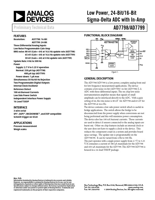
Low Power, 24-Bit/16-BitSigma-Delta ADC with In-Amp Preliminary Technical Data AD7798/AD7799Rev. PrD.Information furnished by Analog Devices is believed to be accurate and reliable.However, no responsibility is assumed by Analog Devices for its use, nor for anyinfringements of patents or other rights of third parties that may result from its use. Specifications subject to change without notice. No license is granted by implication or otherwise under any patent or patent rights of Analog Devices. Trademarks and registered trademarks are the property of their respective companies.One Technology Way, P.O. Box 9106, Norwood, MA 02062-9106, U.S.A. Tel: Fax: 781.326.8703© 2004 Analog Devices, Inc. All rights reserved.FEATURESResolution: AD7798:16-BitAD7799: 24-BitThree Differential Analog InputsLow Noise Programmable Gain AmpRMS noise: 80 nV (Gain = 64) at 16.6 Hz update rate (AD7798) 65 nV (Gain = 64) at 16.6 Hz update rate (AD7799)30 nV (Gain = 64) at 4 Hz update rate (AD7799) Update Rate: 4 Hz to 500 HzPowerSupply: 2.7 V to 5.25 V operationNormal: 330 µA typ (AD7798)400 µA typ (AD7799)Power-down: 1 µA maxSimultaneous 50 Hz/60 Hz RejectionTwo Programmable Digital OutputsInternal Clock OscillatorReference Detect100 nA Burnout CurrentsLow Side Power SwitchIndependent Interface Power Supply16-Lead TSSOPINTERFACE3-wire serialSPI®, QSPI™, MICROWIRE™, and DSP compatibleSchmitt trigger on SCLKAPPLICATIONSPressure measurementWeigh scales FUNCTIONAL BLOCK DIAGRAMFigure 1.GENERAL DESCRIPTIONThe AD7798/AD7799 is a low power, complete analog front end for low frequency measurement applications. The device contains a low noise 24-bit (AD7799)/ 16-bit (AD7798) ∑-∆ ADC with three differential inputs. The on-chip low noise instrumentation amplifier means that signals of small amplitude can be interfaced directly to the ADC. With a gain setting of 64, the rms noise is 80 nV for AD7798 and 65 nV for the AD7799 at 16.6 Hz.T he device contains a low side power switch which is useful in bridge applications. The switch allows the bridge to be disconnected from the power supply when conversions are not being performed and this will minimise power consumption. The device also has 100 nA burnout currents. These currents are used to detect if sensors connected to the analog inputs are burnt out. Other on-chip features include an internal clock so the user does not have to supply a clock to the device. This reduces the component count in a system and provides board space savings. The update rate is programmable on theAD7798/99. It can be varied from 4 Hz to 500 Hz. The part operates with a single power supply from 2.7 V to 5.25 V. It consumes a current of 380 uA maximum for the AD7798 and 450 uA maximum for the AD7799. The AD7799/AD7798 is housed in a 16-lead TSSOP package.AD7798/AD7799Preliminary Technical DataREV. PrD. Page 2 of 17TABLE OF CONTENTSAD7799/AD7798—Specifications..................................................3 Timing Characteristics , ....................................................................6 Absolute Maximum Ratings............................................................8 Pin Configuration and Function Descriptions.............................9 Typical Performance Characteristics...........................................11 On-chip Registers...........................................................................12 Communications Register (RS2, RS1, RS0 = 0, 0, 0)..............12 Status Register (RS2, RS1, RS0 = 0, 0, 0; Power-on/Reset = 0x88).............................................................................................13 Mode Register (RS2, RS1, RS0 = 0, 0, 1; Power-on/Reset = 0x000A). (13)Configuration Register (rs2, RS1, RS0 = 0, 1, 0; Power-on/Reset = 0x0710)....................................................................15 Data Register (RS2, RS1, RS0 = 0, 1, 1; Power-on/Reset =0x0000 (AD7798)/ 0x000000 (AD7799))................................16 ID Register (RS2, RS1, RS0 = 1, 0, 0; Power-on/Reset = 0xX8 (AD7798)/ 0xX9 (AD7799)).....................................................16 OFFSET Register (RS2, RS1, RS0 = 1, 1, 0; Power-on/Reset = 0x8000 (AD7798)/0x800000 (AD7799)).................................17 FULLSCALE Register (RS2, RS1, RS0 = 1, 1, 1; Power-on/Reset = 0x5XXX (AD7798)/0x5XXX000 (AD7799)).....17 TYPICAL APPLICATION.. (17)REVISION HISTORYPrelim D, June 2004: Initial VersionPreliminary Technical DataAD7798/AD7799REV. PrD. Page 3 of 17AD7799/AD7798—SPECIFICATIONS 1Table 1. (AV DD = 2.7 V to 5.25 V; DV DD = 2.7 V to 5.25 V; GND = 0 V; REFIN(+) = 2.5 V; REFIN(-) = 0 V; all specifications T MIN to T MAX , unless otherwise noted.)Parameter AD7798/AD7799B Unit Test Conditions/Comments ADC CHANNEL SPECIFICATION Output Update Rate 4 Hz min nom 500 Hz max nom ADC CHANNEL No Missing Codes 224 16 Bits min Bits min AD7799, f ADC ≤ 125 HzAD7798Resolution 16 Bits p-p Gain = 128, 16.6 Hz Update Rate191618.5Bits p-p Bits p-p Bits p-p Gain = 1, 16.6 Hz Update Rate, AD7799 Gain = 1, 16.6 Hz Update Rate, AD7798 Gain = 64, 4 Hz Update Rate, AD7799Output Noise and Update Rates See Tables in ADCDescriptionIntegral Nonlinearity ±15 ppm of FSR max 3.5 ppm typ, Gain 1 to 32 Offset Error 3±25 ±3 ppm of FSR max µV typ Gain = 64 or 128Offset Error Drift vs. Temperature 4±10 nV/°C typFull-Scale Error 5±10 µV typGain Drift vs. Temperature 4±0.5 ppm/°C typ Gain = 1, 2 ±3 ppm/°C typ Gain = 4 to 128 Power Supply Rejection 90 dB min 100 dB typ, AIN = 50 % of full scale ANALOG INPUTS Differential Input Voltage Ranges ±REFIN/Gain V nom REFIN = REFIN(+) – REFIN(–), Gain = 1 to 128Absolute AIN Voltage Limits2Unbuffered ModeBuffered Mode In-Amp Enabled GND + 30 mV AV DD – 30 mV GND + 100 mVAV DD – 100 mVGND + 300 mVV DD – 1.2V max V min V min V max V min V max Gain = 1 or 2 Gain = 1 or 2 Gain = 4 to 128 Common Mode VoltageIn-Amp EnabledAnalog Input CurrentBuffered Mode or In-Amp Enabled0.5 V min Gain = 4 to 128 Average Input Current ±200 ±1 pA max nA max AIN1(+) – AIN1(-), AIN2(+) – AIN2(-) only.AIN3(+) – AIN3(-).Average Input Current Drift ±2 pA/°C typ Unbuffered Mode Average Input Current ±400 nA/V typGain = 1 or 2Input current varies with input voltage. Average Input Current DriftNormal Mode Rejection 2@ 50 Hz, 60 Hz±50 70 pA/V/°C typ dB min 73 dB typ, 50 ± 1 Hz, 60 ± 1 Hz, FS[3:0] = 10106 @ 50 Hz 84 dB min 90 dB typ, 50 ± 1 Hz, FS[3:0] = 10016 @ 60 Hz 90 dB min 90 dB typ, 60 ± 1 Hz, FS[3:0] = 10006Common Mode Rejection@DC@ 50 Hz, 60 Hz 90 100 dB min dB min AIN = 50% of FS 80 dB typ, FS[3:0] = 10106 50 ± 1 Hz (FS[3:0] = 10016), 60 ± 1 Hz (FS[3:0] =10006)AD7798/AD7799Preliminary Technical DataREV. PrD. Page 4 of 17Parameter AD7798/AD7799B Unit Test Conditions/Comments REFERENCE INPUT REFIN Voltage 2.5 V nom REFIN = REFIN(+) – REFIN(–)Reference Voltage RangeAbsolute REFIN Voltage Limits 0.1 AV DD GND – 30 mVV min V max V min AV DD + 30 mV V max Average reference Input Current 400 nA/V typ Average Reference Input Current Drift ±0.03 nA/V/°C typ Normal Mode Rejection See ANALOG INPUTS Common Mode Rejection See ANALOG INPUTS Reference Detect 0.3 0.65 V min V max NOREF bit Inactive if VREF < 0.3 VNOREF bit Active if VREF > 0.65 VLOW SIDE POWER SWITCHR ONAllowable Current 5 7 20 Ω max Ω max mA max AV DD = 5V AV DD = 3V Continuous Current INTERNAL CLOCKDrift64 ±2% 0.01KHz nom %/°C typ LOGIC INPUTS All Inputs Except SCLK and DIN V INL , Input Low Voltage 0.8 V max DV DD = 5 V 0.4 V max DV DD = 3 VV INH , Input High Voltage 2.0 V min DV DD = 3 V or 5 VSCLK and DIN Only (Schmitt-Triggered Input)V T (+) 1.4/2 V min/V max DV DD = 5 V V T (–) 0.8/1.4 V min/V max DV DD = 5 V V T (+) – V T (–) 0.3/0.85 V min/V max DV DD = 5 V V T (+) 0.9/2 V min/V max DV DD = 3 V V T (–) 0.4/1.1 V min/V max DV DD = 3 VV T (+) - V T (–)Input Currents Input Capacitance 0.3/0.85 ±1 10 V min/V max µA max pF typ DV DD = 3 V V IN = DV DD or GND All Digital InputsLOGIC OUTPUTS V OH , Output High Voltage DV DD – 0.6 V min DV DD = 3 V, I SOURCE = 100 µA V OL , Output Low Voltage 0.4 V max DV DD = 3 V, I SINK = 100 µA V OH , Output High Voltage 4 V min DV DD = 5 V, I SOURCE = 200 µA V OL , Output Low Voltage 0.4 V max DV DD = 5 V, I SINK = 1.6 mAFloating-State Leakage Current ±1 µA max Floating-State Output Capacitance 10 pF typ Data Output Coding Offset BinaryDIGITAL OUTPUTSP1 and P2V OH , Output High Voltage 2V OL , Output Low VoltageV OH , Output High Voltage 2 V OL , Output Low VoltageAV DD – 0.6 0.4 4 0.4 V min V max V min V max AV DD = 3 V, I SOURCE = 100 µA AV DD = 3 V, I SINK = 100 µA AV DD = 5 V, I SOURCE = 200 µA AV DD = 5 V, I SINK = 800 µAPreliminary Technical DataAD7798/AD7799REV. PrD. Page 5 of 17Parameter AD7798/AD7799B Unit Test Conditions/CommentsSYSTEM CALIBRATION2Full-Scale Calibration Limit Zero-Scale Calibration Limit Input Span 1.05 x FS-1.05 x FS0.8 x FS2.1 x FSV max V min V min V max POWER REQUIREMENTS 7Power Supply Voltage V DD – GND IOV DD – GND 2.7/5.25 2.7/5.25 V min/max V min/max Power Supply Currents I DD Current 150 µA max 125 µA typ, Unbuffered Mode 175 µA max 150 µA typ, Buffered Mode, In-Amp Bypassed 380 450 µA max µA max 330 µA typ, In-Amp used (AD7798)400 µA typ, IN-AMP used (AD7799)I DD (Power-Down Mode) 1 µA max1 Temperature Range –40°C to +105°C.2Specification is not production tested but is supported by characterization data at initial product release. 3A System calibration will reduce this error to the order of the noise for the programmed gain and update rate. 4A calibration at any temperature will remove this error. 5Full-scale error applies to both positive and negative full-scale and applies at the factory calibration conditions (AV DD = 4 V). 6FS[3:0] are the four bits used in the mode register to select the output word rate. 7Digital inputs equal to DV DD or GND.AD7798/AD7799Preliminary Technical DataREV. PrD. Page 6 of 17TIMING CHARACTERISTICS 8, 9Table 2. (AV DD = 2.7 V to 5.25 V; DV DD = 2.7 V to 5.25; GND = 0 V, Input Logic 0 = 0 V, Input Logic 1 = DV DD , unless otherwise8 Sample tested during initial release to ensure compliance. All input signals are specified with t R = t F = 5 ns (10% to 90% of V DD ) and timed from a voltage level of 1.6 V.9See and .Figure 3Figure 410These numbers are measured with the load circuit of Figure 2Figure 2 and defined as the time required for the output to cross the V OL or V OH limits. 11SCLK active edge is falling edge of SCLK.12These numbers are derived from the measured time taken by the data output to change 0.5 V when loaded with the circuit of . The measured number is then extrapolated back to remove the effects of charging or discharging the 50 pF capacitor. This means that the times quoted in the timing characteristics are the true bus relinquish times of the part and, as such, are independent of external bus loading capacitances.13RDY returns high after a read of the ADC. In single conversion mode and continuous conversion mode, the same data can be read again, if required, while RDY is high, although care should be taken to ensure that subsequent reads do not occur close to the next output update. In continuous read mode, the digital word can be read only once.Preliminary Technical DataAD7798/AD7799REV. PrD. Page 7 of 17TO OUTPUT PIN+1.6V50pFFigure 2. Load Circuit for Timing CharacterizationCS (I)I = INPUT, O = OUTPUTFigure 3. Read Cycle Timing DiagramI = INPUT, O = OUTPUTCS (I)SCLK (I)DIN (I)Figure 4. Write Cycle Timing DiagramAD7798/AD7799Preliminary Technical DataREV. PrD. Page 8 of 17ABSOLUTE MAXIMUM RATINGSTable 3. (T A = 25°C, unless otherwise noted.)Parameter Rating AV DD to GND DV DD to GND -0.3V to +7V-0.3V to +7VAnalog Input Voltage to GND –0.3 V to AV DD + 0.3 VReference Input Voltage to GND –0.3 V to AV DD + 0.3 VDigital Input Voltage to GND –0.3 V to DV DD + 0.3 VDigital Output Voltage to GND AIN/digital Input Current –0.3 V to DV DD + 0.3 V10 mAOperating Temperature Range –40°C to +105°CStorage Temperature Range –65°C to +150°CMaximum Junction Temperature 150°CTSSOP θJA Thermal Impedance 97.9°C/WθJC Thermal Impedance 14°C/WLead Temperature, SolderingVapor Phase (60 sec) Infrared 215°C 220°C Stresses above those listed under Absolute Maximum Ratings may cause permanent damage to the device. This is a stress rating only; functional operation of the device at these or any other conditions above those listed in the operational sections of this specification is not implied. Exposure to absolute maximum rating conditions for extended periods may affect device reliability.Preliminary Technical Data AD7798/AD7799 PIN CONFIGURATION AND FUNCTION DESCRIPTIONSFigure 5. Pin ConfigurationREV. PrD. Page 9 of 17AD7798/AD7799 Preliminary Technical Data PinNo. Mnemonic Function16 DIN Serial Data Input to the Input Shift Register on the ADC. Data in this shift register is transferred to the controlregisters within the ADC, the register selection bits of the communications register identifying theappropriate register.REV. PrD. Page 10 of 17REV. PrD. Page 11 of 17TYPICAL PERFORMANCE CHARACTERISTICSFigure 6.Figure 7.Figure 8.Figure 9.Figure 10.Figure 11.ON-CHIP REGISTERSThe ADC is controlled and configured via a number of on-chip registers, which are described on the following pages. In the following descriptions, set implies a Logic 1 state and cleared implies a Logic 0 state, unless otherwise stated.COMMUNICATIONS REGISTER (RS2, RS1, RS0 = 0, 0, 0)The communications register is an 8-bit write-only register. All communications to the part must start with a write operation to the com-munications register. The data written to the communications register determines whether the next operation is a read or write operation, and to which register this operation takes place. For read or write operations, once the subsequent read or write operation to the selected register is complete, the interface returns to where it expects a write operation to the communications register. This is the default state of the interface and, on power-up or after a reset, the ADC is in this default state waiting for a write operation to the communications regis-ter. In situations where the interface sequence is lost, a write operation of at least 32 serial clock cycles with DIN high returns the ADC to this default state by resetting the entire part. Table 5 outlines the bit designations for the communications register. CR0 through CR7 indi-cate the bit location, CR denoting the bits are in the communications register. CR7 denotes the first bit of the data stream. The number in brackets indicates the power-on/reset default status of that bit.Table 6. Register SelectionSizeRS2 RS1 RS0 Register Register0 0 0 Communications Register during a Write Operation 8-Bit0 0 0 Status Register during a Read Operation 8-BitRegister 16-Bit0 0 1 Mode0 1 0 ConfigurationRegister 16-Bit0 1 1 Data Register 24-Bit (AD7799)16-bit (AD7798)1 0 0 IDRegister 8-BitRegister 8-Bit1 0 1 IO1 1 0 Offset Register 24-Bit (AD7799)16-bit (AD7798)1 1 1 Full-Scale Register 24-Bit (AD7799)16-Bit (AD7798)REV. PrD. Page 12 of 17STATUS REGISTER (RS2, RS1, RS0 = 0, 0, 0; POWER-ON/RESET = 0x88)The status register is an 8-bit read-only register. To access the ADC status register, the user must write to the communications register, select the next operation to be a read, and load bits RS2, RS1 and RS0 with 0. Table 7 outlines the bit designations for the status register.SR0 through SR7 indicate the bit locations, SR denoting the bits are in the status register. SR7 denotes the first bit of the data stream. The number in brackets indicates the power-on/reset default status of that bit.MODE REGISTER (RS2, RS1, RS0 = 0, 0, 1; POWER-ON/RESET = 0x000A)The mode register is a 16-bit register from which data can be read or to which data can be written. This register is used to configure the Low Side Power Switch, select the mode of the ADC and select the ADC update rate. Table 8 outlines the bit designations for the mode register. MR0 through MR15 indicate the bit locations, MR denoting the bits are in the mode register. MR15 denotes the first bit of thedata stream. The number in brackets indicates the power-on/reset default status of that bit. Any write to the setup register resets the modulator and filter and sets the RDY bit.MR15 MR14 MR13 MR12 MR11 MR10 MR9 MR8MD2(0) MD1(0) MD0(0) PSW(0) 0(0) 0(0) 0(0) 0(0)MR7MR6MR5MR4MR3MR2MR1MR0(0) (0) 0(0) 0(0) FS3(1) FS2(0) FS1(1) FS0(0)Table 8. Mode Register Bit DesignationsBit Location Bit Name DescriptionMR15–MR13 MD2–MD0 Mode Select Bits. These bits select the operational mode of the AD7798/AD7799 (See Table 9).MR12 PSW Power Switch Control Bit.Set by user to close the power switch PSW to GND. The power switch can sink up to 20 mA.Cleared by user to open the power switch.When the ADC is placed in power-down mode, the power switch is opened.MR11-MR4 0 These bits must be programmed with a Logic 0 for correct operation.MR3-MR0 FS3-FS0 Filter Update Rate Select Bits (see Table 10).REV. PrD. Page 13 of 17REV. PrD. Page 14 of 17REV. PrD. Page 15 of 17Table 10. Update Rates AvailableFS3 FS2 FS1 FS0 f ADC (Hz) Tsettle (ms) Rejection @50 Hz/60 Hz0 0 0 0 x x 0 0 0 1 500 5 0 0 1 0 250 8 0 0 1 1 125 16 0 1 0 0 62.5 32 0 1 0 1 50 400 1 1 0 41.6480 1 1 1 33.3 601 0 0 0 19.6 101 90 dB (60 Hz only) 1 0 0 1 16.6 120 84 dB (50 Hz only)1 0 1 0 16.6 120 70 dB (50 Hz and 60 Hz) 1 0 1 1 12.5 160 67 dB (50 Hz and 60 Hz) 1 1 0 0 10 200 69 dB (50 Hz and 60 Hz) 1 1 0 1 8.33 240 73 dB (50 Hz and 60 Hz)1 1 1 0 6.25 320 74 dB (50 Hz and 60 Hz) 1 1 1 1 4.1748075 dB @ 50/60 HzCONFIGURATION REGISTER (RS2, RS1, RS0 = 0, 1, 0; POWER-ON/RESET = 0x0710)The configuration register is a 16-bit register from which data can be read or to which data can be written. This register is used to configure the ADC for unipolar or bipolar mode, enable or disable the buffer, enable or disable the burnout currents, select the gain and select the ana-log input channel. CON0 through CON15 indicate the bit locations, CON denoting the bits are in the configuration register. CON15 denotes the first bit of the data stream. The number in brackets indicates the power-on/reset default status of that bit.REV. PrD. Page 16 of 17Bit Location Bit NameDescription0 1 0 4 ±625 mV 0 1 1 8 ±312.5 mV 1 0 0 16 ±156.2 mV 1 0 1 32 ±78.125 mV 1 1 0 64 ±39.06 mV 1 1 1 128±19.53 mVCON7-CON6These bits must be programmed to a logic 0 for correct operation. CON5 REF_DETEnables the Reference Detect Function.When set , the NOREF bit in the status register indicates when the reference being used by the ADC is not present.When cleared , the reference detect function is disabled.CON4 BUFConfigures the ADC for buffered or unbuffered mode of operation. If cleared , the ADC operates in unbuffered mode, lowering the power consumption of the device. If set , the ADC operates in buffered mode, allowing the user to place source impedances on the front end without contributing gain errors to the system.CON3 0This bits must be programmed to a logic 0 for correct operation. CON2-CON0 CH2-CH0Channel Select bits.Written by the user to select the active analog input channel to the ADC. CH2 CH1 CH0 Channel Calibration Pair 0 0 0 AIN1(+) – AIN1(-) 0 0 0 1 AIN2(+) – AIN2(-) 1 0 1 0 AIN3(+) – AIN3(-) 2 0 1 1 AIN1(-) – AIN1(-) 0 1 0 0 Reserved 1 0 1 Reserved 1 1 0 Reserved1 1 1 VDDMonitorDATA REGISTER (RS2, RS1, RS0 = 0, 1, 1; POWER-ON/RESET = 0x0000 (AD7798)/ 0X000000 (AD7799))The conversion result from the ADC is stored in this data register. This is a read-only register. On completion of a read operation from this register, the RDY bit/pin is set.ID REGISTER (RS2, RS1, RS0 = 1, 0, 0; POWER-ON/RESET = 0xX8 (AD7798)/ 0xX9 (AD7799))The Identification Number for the AD7798/AD7799 is stored in the ID register. This is a read-only register.IO REGISTER (RS2, RS1, RS0 = 1, 0, 1; POWER-ON/RESET = 0x00)The I/O register is an 8-bit register from which data can be read or to which data can be written. IO0 through IO7 indicatethe bit locations, IO denoting the bits are in the IO register. Table 12 outline the bit designations for the IO register. IO7 denotes the first bit of the data stream. The number in brackets indicates the power-on/reset default status of that bit.IO7 IO6 IO5 IO4 IO3 IO2 IO1 IO0 0 IOEN(0) IO2DAT(0) IO1DAT(0) 0 0 0 0Table 12. I/O register Bit DesignationsBit Location Bit NameDescriptionIO7 0 These bits must be programmed to a logic 0 for correct operation.IO6IOENConfigures the pins AIN3(+)/P1 and AIN3(-)/P2 as analog input pins or digital output pins. When this bit is set , the pins are configured as digital output pins P1 and P2.When this bit is cleared , these pins are configured as analog input pins AIN3(+) and AIN3(-).IO5-IO4 IO2DAT/IO1DAT P2/P1 Data. IO3-IO0 0 These bits must be programmed to a logic 0 for correct operation.OFFSET REGISTER (RS2, RS1, RS0 = 1, 1, 0; Power-on/Reset = 0x8000 (AD7798)/0x800000 (AD7799))The offset register holds the offset calibration coefficient for the ADC. The power-on-reset value of the internal zero-scale calibration coefficient register is 8000 hex (AD7798)/800000 hex (AD7799). The AD7798/AD7799 has 3 offset registers. Each of these registers is a 16/24-bit read/write register.However, when writing to the offset-scale registers, the ADC must be placed in power down mode or idle mode. This register is used in conjunction with its associated full-scale register to form a register pair. The power-on-reset value is automatically overwritten if an internal or system zero-scale calibration is initiated by the user.FULLSCALE Register (RS2, RS1, RS0 = 1, 1, 1; Power-on/Reset = 0x5XXX (AD7798)/0x5XXX000 (AD7799)) The full-scale register holds the full-scale calibration coefficient for the ADC. The AD7798/AD7799 has 3 full-scale registers. Each of these registers is a 16/24-bit read/write register.However, when writing to the full-scale registers, the ADC must be placed in powerdown mode or idle mode. The full-scale error of the AD7799/AD7798 is calibrated in the factory at both a gain of 1 and 128. Therefore if the gain is set to 128, as on power-on, or if the gain is set to 1, the factory calibrated internal full-scale coefficients are automatically loaded into the full-scale registers of the AD7799/AD7798. Therefore, every device will have different default coefficients. The user can overwrite these values, if required. These coefficients will be automatically overwritten if an internal or system full-scale calibration is initiated by the user. A full-scale calibration should be performed when the gain is changed. When the gain equals 128, internal full-scale calibrations cannot be performed.TYPICAL APPLICATIONFigure 12. P R 0 4 8 5 6 -0 -6 / 0 4 ( P r D )REV. PrD. Page 17 of 17。

2009.3.30····························································· 1 ········································································ 4 ········································································ 9 ········································································ 21 ········································································ 36 ········································································ 45 ········································································ 48 ········································································ 59 ········································································ 62 ········································································ 63 ········································································ 65exclamation (!) symbol 1/2" tool + right-handed 1/2" tool 1/2 ratio more than quarter indexes the spindle at 1º incremental 3 - Ø3.3 drill 200VAC over current alarm AC servo motor Point A = Ps position Point B = Pa position CCW (counterclockwise) Cincom M series Cincom M series dedicated macro Cincom M series basic manual感叹号 (!) 功能 1/2"刀具+右1/2"刀具 1/2减速 1/4以上 毎1°分度 3 -Ø3.3钻头 200VAC过载警报 AC伺服电机 A点=Ps点 B点=Pa点 CCW (左转,逆时针方向转) Cincom M系列 CINCOM M系列专用宏程序 Cincom M使用说明书 [基础篇]200VAC过电流警报Cincom Introduction Manual (guide bushing type) Cincom (导套式) 使用说明书 [入门篇] CW (clockwise) C coordinate C axis (S6 = tool spindle of the back 3-spindle tool post C-axis cancel backward rotation of the C axis C axis zero return C axis coordinate system setting C axis coordinate C axis control servo motor C axis speed rotate the C axis 180 degrees DC code provided DC code output DC code flow DC control DOS-format floppy disk D-cutting EC specification EOB output FDD connector FDD (floppy disk drive) G functions (G codes) G code list G code function group G-code conversion G command G modal HDD lamp HEX data interface diagnostic information Troubleshooting with I/F-diagnosis IC card unit IC card storage area CW (右转,顺时针方向转) C坐标 C轴 (S6=背面刀具主轴) 取消C轴 C轴反转 C轴原点返回 C轴坐标系设定 C轴坐标值 C轴控制伺服电机 C轴的转速 C轴180°旋转 有DC编码 DC符号輸出 DC符流程控制 DC控制 DOS格式的软盘 D切削加工 EC规格 EOB输出 FDD接头 FDD装置 G功能 (G编码) G编码一览表 G编码功能组 G编码变换 G指令 G模态 HDD显示灯 HEX数据 I/F诊断 (接口诊断信息) 通过I/F诊断发现 IC卡装置 IC卡存储区 C轴逆转IC card reader/writer LCD back light fields on the liquid crystal display (LCD) LRL-3 or its equivalent mcp_no setting error MDI (manual data input) operation MDI input area MDI status MDI mode feed per revolution (mm/rev) M functions (M Codes) M code M code list simultaneous command for 4 sets of M-code NC alarm list of NC alarm messages NC machine grounding grounding of the NC machine NC lathe NC unit NC power-on NC unit trouble NC servo interface (MCP) NC system alarm contents of the NC unit NC program structure NC reset status (RST) NOP: network option operating system (OS) PCMCIA card slot PCMCIA card drive PCMCIA card drive connector mounting the PCMCIA card dismounting the PCMCIA card PLC ALM PLC control PLC data RS-232C connector RS-232C communications parameters curved part R tool nose radius stabilizer device for SL (CAV) SRAM data S functions S codes command ranges of the S codesIC卡读写装置 LCD背面照明 LCD各显示栏目 LRL-3或相当于LRL-3的产品 mcp_no设定误差 MDI运转 MDI输入区域 MDI状态 MDI方式 mm/rev进给 M功能 (M编码) M编码 M编码一览表 4组M代码同时指令 NC警报 NC警报信息一览表 NC机械接地 NC机械的接地 NC车床 NC装置 接通NC电源 NC的故障 NC的伺服接口 (MCP) NC的系统警报 NC的内容 NC程序的结构 NC复位状态中 (RST) NOP: 网上任选 (项) OS (操作系统) PCMCIA卡插口 PCMCIA卡驱动装置 PCMCIA卡驱动装置接头 PCMCIA卡的安装 PCMCIA卡的取出 PLC警报 PLC控制用 PLC常数 (数据) RS-232C 接头 RS232C通讯参数 R凹进部分 刀尖半径 SL (CAV) 用稳定 (支撑) 装置 SRAM数据 S功能 S编码 S编码的指令范围LCD背景灯mcp_no设定错误R弯曲部分TI axis TI axis setting TI axis zero adjustment TI axis stroke TI axis control motor T functions (T codes) T codes command values of T codes T command T command alarm U argument W argument X1 axis X1 stroke X1-axis ball screw workpiece coordinate of X1 axis X2 axis feed timing belt machine coordinate of X2 axis X2 turret X3 and Z3 axis machine zero point X3 machine zero point machine coordinate of X3-axis workpiece unloading position X-Y plane X axis coordinate X-axis direction X-axis direction Y1 gang tool post Y-shaped terminals Z1 axis limit in the plus direction Z2 superimposed on Z1 positioning of the Z2 axis for product separation Z-X plane selection Z axis coordinate system setting φ3.5 drilled through-hole (chamfering of both openings C1) steel rod of φ 70TI轴 TI轴原点设定 TI轴原点调整 TI轴的行程 TI轴控制电机 T功能 (T编码) T编码 T编码指令值 T指令 T指令警报 U自变量 W自变量值 X1轴 X1轴的行程 X1轴滚珠丝杆 X1轴工件坐标 X2轴进给用同步皮带 X2轴机械坐标 X2转塔 (刀架) X3,Z3轴机械原点 X3机械原点 X3轴工件取出位置的机械坐标 XY平面 X轴坐标值 X轴方向 X轴方向 Y1排刀刀具台 Y型端子 Z1轴的 (+) 正极限值 Z2在Z1上重叠 Z2轴产品回收定位 ZX平面加工选择 Z轴坐标系设定 φ3.5 钻头贯通 (两侧孔口端面倒角C1) φ70钢棒Y型接头arc welding machine grounding wire mounting screw grounding terminal arm red sticker accessories play attachment adapter outer dia. adapter type adapter name heavy curtain compressed air back turning back turning process back turning tool drilling tool drilling cycle canned cycle drilling hole diameter absolute absolute command oil-cake residues stability draining oil drain hole oil splash protection cover oil leak incorrect, error alarm ALM alarm lists tolerances of speed fluctuation rate alarm information alarm no. list of messages displayed when the ALM (alarm) lamp lights alarm messages ALM (alarm) lamps alarm lists and solution alarm history reset the alarm rough machining preset fluctuation rate alkart net alkart pro alkaline content alphabetic characters aluminum电弧焊接机 (接) 地线安装用螺丝 接地 (线) 接头 臂 红色的 (贴纸) 标签 附属品 间隙 附属装置 连接器外径 连接器型 连接器名称 厚窗帘 压缩空气 后车削 后车削加工 后车削刀具 钻孔刀具 钻孔周期 钻孔用固定周期 孔径 绝对 绝对指令 油渣、剩油残渣 油分离特性 排油 排油孔 防止溅油罩 漏油 错误 警报 警报 警报一览表 标准 (速度) 变动率容限 警报内容 警报N0. 警报显示灯亮时的信息一览表 警报信息 警报灯 警报表和处理方法 警报履历 解除警报 粗加工 预先设定的变动率 Alkart网络 Alkart网络装置 碱性 英文字母 (表) 铝附件、配件指直径稳定性误差标准 (速度) 变动率的容许极限AlkartNetaluminum pipe aluminum nameplate adjustment oil-separation characteristics??? unclamping unclamping and clamping positions unclamping position safety operation safety distance safety shoes safety device general notes on safety stable position amplifier铝管 铝制标牌 嵌合 防止起泡 松开 松开和夹紧位置 松开位置 安全运转 安全距离 安全鞋 安全装置 有关安全的一般注意事项 稳定位置 传动设备调整 解开abnormal sound non-conformed material non-conformed material machining non-conformed material phase adjustment non-conformed material phase adjustment chuck sleeve for non-conformed materials back chucking device for non-conformed materials odor abnormality procedures to fix machine troubles worn-out abnormal abrasion phase angle of the phase shift amount of the phase shift adjusting the phases 1 inch specification 1 index positioning positioning hole positioning pin system 1-axis lathe temporary stop state position data up to ten menus in one row constant 1-tool vertical sleeve holder Idemitsu relocation new work site preparation for relocation feed position operating time operating time display block which axes do not move声音异常 异形材料 异形材料加工 异形材料加工相位调整 异形材料相位调整 异形材料用夹头套筒 异形材料背面主轴夹头装置 气味异常 异常 异常状态的处理方法 异常损耗 异常磨耗 相位 相位位移角度 相位位移量 相位调整 1英寸规格 1分度 定位 定位孔 定位销方式 1轴车床 暂时停止 (状态) 位置数据 一列最多10个菜单 不变 1把直立套筒夹 出光 重新安置 新的安置地点 重新安置的准备 移动位置 操作时间 操作时间显示 不移动的程序段单轴车床运行时间 运行时间显示move command feed rate move and copy feed distance different pitches permitted explanation casting illustrations inflammable incremental indicator index intelligent servo motor intelligent servo motor (ball screw integrated) input in-process移动指令 移动速度 移动和复制 (拷贝) 移动量 允许不同螺距 意思 (内涵) 铸件 插图 易燃 (之物) 增量 指示器 分度 智能伺服电机 智能伺服电机 (整体滚珠丝杆) 输入 (INPUT) 加工中解释、说明增加的 显示器window window display field up arrow buoy buoy oil level receiver box transfer commands (e.g., transfer command) moving parts dimly urethane urethane tube overwrite overwrite mode operation running time preparation ready for operation (RDY) preparation functions preparation process preparation mode operation status general notice during operation operation status relation between operation status display colors and the machine status display in the operation status display field operation status display field operation control mode resuming operation pre-operation check窗口 窗口显示栏 向上箭头 浮标 浮标指示油 (面) 位 (置) 接收箱 接收传送 接受传送 (等) 指令 移动部分 薄的 聚氨酯 聚氨酯软管 重写 重写模式 运转 运转时间 运行准备 运行准备结束状态 (RDY) 运行准备功能 运行准备过程中 运行准备方式 运转状态/操作状态 运转上的注意事项 运转状态 运转状态的显示色与机械状态的关系 运转状态的显示 (栏) 内容 运转状态显示栏 运转操作方式 运转的重新开始 运转前的检查用于窗口式操作系统<6.2 > <6.2 Preparing for Operation>operation mode display in the operation mode display field operation mode display field delivery vehicle procedure to relocate运转方式 运转方式的显示内容 运转方式显示栏 搬运车 搬运方法air gun styro-foam air pressure air chuck air chuck regulator air blower off air blower on air blower air blow solenoid valve air hose alphanumeric keys alphanumeric characters LCD (liquid crystal display) Esso Esso Standard Oil Phoebis K68 error and alarm messages error detect on/off error number elbow encoder cable encoder trouble circular cutting as if it draws circular be in the circular motion circular machining circular radius specification circular interpolation circular interpolation (clockwise) circular interpolation (counterclockwise) circular interpolation feed circular constant major causes of spread of fire end of block (EOB) end mill end mill (2 cutting edges) amount of end milling protrusion endless screw(空) 气枪 气泡垫 气压 气动卡盘 气动卡盘用调节器 鼓 (吹) 风机OFF 鼓 (吹) 风机ON 鼓 (吹) 风机装置 鼓 (吹) 风机用电磁阀 空气软管 英文数字键 英文数字 液晶显示 (器) (LCD) 诶索 诶索标准石油Phoebis K68 错误、警报和信息 错误检测ON/OFF 错误号码 弯管 编码器电缆 编码器的故障 圆弧切削 圆弧 (就像划圆一样的) 圆弧移动 圆弧加工 指定圆弧半径R 圆弧插补 圆弧插补 (顺时针方向旋转) 圆弧插补 (逆时针方向旋转) 圆弧插补进给 圆周率 (≒3.14) 火势蔓延的主要原因 程序段结束 立铣刀 双刃立铣刀 端铣刀伸出 (部分) 的安装 蜗杆喷枪 一种保护性塑料包装材料字母数字键弯管接头oil seal auto bar loader/feeder oil type oil pan oil-supplied drilling oil light油封 油压式棒料供给装置 油盘 供油钻孔 油灯debossed brass brass module application program larger chips override override function override dial override no limit overrun overrun axis resetting an overrun alarm depth feed axis feed command system feed rate feed rate override (FEED RATE OVERRIDE) pressure claw push-button switches inquiry about trouble request for inquiry optional stop optional offset offset value offset data input state in the offset mode operation error your specified color appearance凹进状态 黄铜 黄铜模块 应用程序 大 (块) 切屑 进给倍率 进给倍率功能 进给倍率开关 进给倍率无限制 超速 超速轴 超速警报的复位 深度 进给轴 进给指令方式 进给速度 超过进给速度 压紧卡爪 按钮开关 咨询时的注意事项 任选停止 任选 补偿 补偿设定值 补偿数据 补偿方式下的输入状态 操作误差 贵社指定的外观颜色超过、越程 越程警报的复位操作错误deleting the character following the cursor光标后面的文字删除deleting the character preceding the cursor光标前的文字删除card drive卡驱动装置cartridge-type tank capacity筒形油箱容量karbic弯曲的、曲线的弧齿的 air inlet进气部分line feed code换行编码outer diameter外径simultaneous machining for outer and innerdiameters外径 - 内径同时加工outer diameter machining外径加工outer diameter machining外径切削 (加工)outer diameter machining (turning)外径切削 (加工) (车削)outer diameter grooving process外径切槽加工free-cutting steel易切削钢turning tool车削刀具start开始start position开始点automatic return to the start position开始点自动复归自动返回到开始点 start position operation开始点操作command to advance the workpiece separator withthe start point queuing function开始点汇合功能工件回收装置前进指令vendor公司名称 (销售商) outer circumference外周outer diameter drilling (secondary machining)外周钻孔 (2次加工)cross-drilling high speed spindle外周钻孔高速 (型) 主轴cross-drilling spindle外周钻孔主轴outer diameter tapping spindle外周钻孔攻丝主轴cross-drilling adjustable spindle外周钻孔调整 (型) 主轴product separator回收装置cross-tapping spindle外周攻丝主轴横向攻丝主轴 outer diameter milling外周铣削外径铣削regenerative resistor mount section再生 (反馈) 电阻器安装部分rotational phase旋转相位rotary tool旋转刀具3 rotary tools3把旋转刀具rotary tool fixing bolt旋转刀具固定螺栓gang tool post for rotary tools旋转刀具装置two stations of the gang tool post for rotary tools旋转刀具装置的2工位tool spindle speed旋转刀具的转速setting a rotary tool旋转刀具的安装 (调整)with a rotary tool使用旋转刀具时synchronized cross tapping by rotary tool使用旋转刀具的同步外周攻丝加工synchronized end face tapping by rotary tool使用旋转刀具的同步端面攻丝加工rotary axis旋转轴spindle speed转速speed clamp转速固定转速限制 speed command转速指令speed-regulated area转速的稳定区域speed adjustment failure转速调整不良rotation speed旋转速度rotational rate转速比rotary part旋转部分rotation direction旋转方向guide sleeve导向套筒导向轴套 guide pipe导管guide bushing导套guide bushing air seal导套气封guide bushing drive导套驱动guide bushing drive device导套驱动装置guide bushing drive motor导套驱动电机timing belt for driving the guide bushing导套驱动用同步皮带guide bushing sliding portions导套滑动部分automatic adjustment for guide bushing clearancefunction导套间隙自动调整功能manual adjustment for a guide bushing clearance导套间隙手动调整guide bushing spindle motor alarm导套主轴电机警报recovery from guide bushing spindle motor alarm导套主轴电机警报的恢复guide bushing inner sleeve hole导套套筒内孔的状态guide bushing device导套装置mounting/adjusting a guide bushing device导套装置的安装/调整cross-sectional view of guide bushing导套断面图adjusting a guide bushing clearance导套调整guide bushing adjustment nut导套调整螺母guide bushing adjustment wrench导套调整用扳手 replacing/adjusting the guide bushing导套的替换、调整automatic adjustment of guide bushing导套的自动调整操作procedures to solve the problem related with theguide bushing导套周围发生异常时的处理方法guide bushing motor导套电机guide bushing unit导套装置guideline指南outer/inner diameter machining内外径加工external alarm外部警报external error外部误差外部错误external storage device外部存储装置外部记忆装置 recovery from external device alarms外部装置警报的恢复external tape reader外部纸带 (磁带) 读出器external input/output device外部输入输出装置foreign substance外部的异物circuit diagram电路图counter计数器counter switch计数器开关counter setup记数器设定counter setting计数器的设定burr毛刺flammable items易燃之物 brackets [ ]方括号 [ ] hook wrench钩形扳手 extension扩展名extended multi-axis and multi-line control system扩展多轴多系统混合控制系统storage destination储存指定地点square spring矩形弹簧角形弹簧names and functions of the unit parts各部件的名称和功能chipped破碎basket筐machining feed rate加工进给速度machining start position (point B)加工开始点 (B点)加工开始位置 machining diameter加工直径axis control group加工系统轴控组machining cycle加工周期total quantity of machined workpieces已经加工的工件总数machining end position加工结束点machined parts加工过的部品machining drawing加工图number of corners of a polygon to be machined被加工多角形的角的数量number of gear teeth to be machined被加工齿轮的齿数machining length加工长度machining data加工数据value specified for "1 bar stock O.D." in themachining data加工数据的“1棒料外径 (直径) ”的值value specified for "2 tool positioning point (DIA)"in the machining data加工数据的“2刀具待机点 (直径) 棒料外径+”的值creating and editing machining data程序的编制和编辑 explanation of machining加工数据的说明entering, changing, or registering machining data加工程序的输入、变更和登录machining positions加工点machining pattern加工模式machining pattern cancel取消加工模式machining pattern setting设定加工模式w: Machining width (mm)加工宽度 (mm)machining radius加工半径machining program加工程序selecting a machining program加工程序的选择machining layout加工配置图specific argument for basket筐专用的自变量workpiece collection with the basket使用筐进行工件回收 fire hazard火灾bevel gear圆锥齿轮bevel gear teeth圆锥齿轮的轮齿incremental input增量输入virtual X-Y control虚 (拟) X-Y控制virtual tool nose position虚 (拟) 刀尖位置 virtual tool nose number虚 (拟) 刀尖号码 rattle卡搭声single-ended wrench单口扳手cutter刀具cutting thickness刀具厚度cutter diameter刀具直径inner diameter of the cutter刀具内径cutter width刀具宽度cutter radius刀具半径overcurrent过电流recovery from overcurrent alarms过电流警报的恢复moving part可 (移) 动部件movable section可 (移) 动部分excessive force剩余力when corners are rounded (R)当角是(外)圆角时Y-wrench叉形带销扳手overheat过热flammable易燃性材料cover mounting screw(保护) 罩的固定螺丝be overloaded过载状态超载状态adjustable angle spindle可变倾斜式主轴可变角式主轴 paper adhesive tape纸胶带gummed paper tape胶带screen group name屏幕组名称screen operation屏幕操作deleting data in screen删除屏幕显示数据screen functions屏幕功能lower right of the screen屏幕右下screen name屏幕名称color liquid crystal display (LCD)彩色液晶显示 (器) (LCD)empty chucking (chucking with no bar material)空夹持 (无材料状态下的夹持)temporarily secure临时固定overwork过劳过度劳动simplified cut-off tool breakage detection简易型切断刀具折断检测simplified cut-off tool breakage detection function简易切断刀具折断检测功能interval间隔ventilation通风environmental file环境文件monitor监视interference干涉interference check干涉检查interference check alarm干涉检查警报recovery from interference check alarms干涉检查警报的恢复 interference check function干涉检查功能enabling/disabling the interference check function干涉检查的有效/无效 interference component干涉部件solids of interference components干涉部件构成整体interference area干涉区域interference area alarm干涉区域警报interference components on which checks are made干涉检查元件 (构件)dry waste cloth干布through-hole贯通孔through-hole machining贯通孔加工 through-hole diameter贯通孔直径through-hole knock-out jig advance/retract贯通孔顶料夹具前进/后退knock-out for the workpiece with through-hole贯通孔顶料夹具的顶料knock-out jig for through-hole workpieces贯通孔工件用顶料夹具through-hole knock-out jig贯通孔工件用顶料夹具through-hole position贯通位置electric shock触电electric shock accident触电事故sensor sensitivity灵敏度 (传感器的)sensitivity current感应电流management area管理区域key handle键手柄key grooving键槽加工key name键名称memory size记忆尺寸machine alarm机械警报machine transfer detection alarm機床移動検測警報machine position data机械位置数据mechanical operation section trouble机械动转部分的故障machine operator机械操作人员name of each machine components机械各部位的名称movable sections of the machine机械的可 (移) 动部分mechanical system机械系统machine zero point机械原点machine coordinate机械坐标machine coordinate system机械坐标系machine specifications机械规格machine status display机械状态显示front view of the machine机械正面图machine vibration机械振动machine values机械值mechanical机械的mechanical transmission section trouble机械传送系统的故障machine operation speed机械运转速度machine failure机械的异常transfer and reinstallation of machine机械的移动设置outside dimensions and layout of the machine机械的外形尺寸与配置图machine structure机械的结构machine component机械构造物机器的构件、机器的组成部分 machine status机械的状态machine operation机械的运转状况machine coating color机械的涂装颜色rear of machine机械背面rear view of the machine机械背面图machine number机械编号machine variable机械变量machine body 机械实体机械本体机械主体机身be vaporized气化hazardous situation危险的状况symbol记号mechanical units机械装置coolant diluted state稀释状态 (切削油的) diluents稀释水 (剂)dilution methods稀释方法axis control group记述系统reference position基准位置reference coordinate axis基准轴reference cross hairs基准十字线reference point基准点scratch划痕foundation基础anchor bolts地脚螺栓predetermined range规定变动宽度 (范围) orbit C轨道Cprocedure if the machine fails to start机械不启动时的对应方法保守 <5.6.1 起動がかからない> は<5.6.1 无法启动>in-machine tool set function机内刀具调整功能in-machine unloading/loading unit机内手动 (装料/卸料) 装置board基板注脚垫板、基板 basic configuration基本构成basic configuration select field基本构成选择栏feed axes基本轴进给轴model机械名称机型gear齿轮reverse rotation反转reverse rotation command反转指令reverse operation逆行backward execution逆行 (逆方向执行)run backward逆行运转cap nut盖形螺母face end of the cap nut盖形螺母的端面replacing the cap nut盖形螺母的替换gear ratio齿轮速比传动比character bit字节character length字长bar loader供材机loader disconnect供材机分离bar loader torque供材机扭矩hold暂停临时中止hold state暂停状态临时中止状态enter the hold state进入暂停状态进入临时中止状态 9-tool vertical holder9把直立刀架oil inlet加油口lubrication润滑油润滑脂lubrication list润滑油一览表润滑脂一览表line行deleting data in lines删除数据行emphasize the text强调 (文字)high-tension power control unit高压动力控制装置高压电源控制装置 drill钻头removal of chips切屑的处理排屑chip切屑chip collector切屑接受chip receiver box切屑回收箱chip receiving area切屑接受部chip remover rod切屑清除棒bottom plate of the chip pool切屑堆置处的底板chip outlet door切屑 (排) 出口chip outlet door切屑 (排) 出口的门chip entanglement切屑块infeed direction横切方向横向进给方向infeed横向进给cut切割emergency紧急emergency situation紧急事态action of emergency situations紧急事态的对应措施emergency stop紧急停止proximity sensor接近 (式) 传感器metal fire extinguisher金属火灾用灭火器metallic section金属部分metal brush金属刷joint快换管接头pneumatic circuit diagram气动电路图空压电路图pneumatic device气动装置空压装置pneumatic piping气动配管气压配管pneumatic piping diagram气动配管图气压配管图even parity偶数奇偶效验air conditioner空调设备unexpected incident偶然事故coolant nozzle冷却剂喷嘴coolant pump冷却泵delimitter code分隔符号wedge楔 (形) 块wedge release tap楔 (形) 块的攻丝outer diameter machining with tool on the gang toolpost使用排刀刀具进行外径加工gang tool排刀gang outer diameter turning tool排刀外径车刀排刀外径旋转刀具 rotary tool on the gang tool post排刀旋转刀具rotary tool spindle drive unit of the gang tool post排刀旋转刀具驱动装置rotary tool spindle of the gang tool post排刀旋转刀具主轴rotary tools on the gang tool post排刀旋转刀具rotary tool holder of the gang tool post排刀旋转刀架gang tool spindle排刀刀具主轴疏刀刀具主轴gang tool spindle reverse rotation排刀刀具主轴反转gang tool spindle drive motor排刀刀具主轴驱动电机 gang tool spindle forward rotation排刀刀具主轴正转gang tool spindle stop排刀刀具主轴停止gang tool spindle motor排刀刀具主轴电机gang tool post spindle motor alarm排刀刀具主轴电机警报 high-speed rotary tool spindle of the gang tool post排刀高速旋转刀具主轴 gang tool post return position排刀后退点gang tool return operation排刀刀具后退动作turning tools on the gang tool post排刀车削用刀具selection of a tool on the gang tool post排刀刀具选择gang tool select command排刀刀具选择指令tool on gang tool post排刀刀具distance of each tool on gang排刀刀具的间隔longitudinal position of the sleeve holder for thegang tool排刀套筒夹的纵向位置milling interpolation with a gang tool使用排刀刀具进行铣削插补gang tool post in the longitudinal direction排刀的纵向 (纵向的排刀)gang tool post排刀刀具台end face drilling spindle for gang tool排刀刀具用端面钻孔主轴 opening edge开口 (处)tapered part at the opening edge开口 (处) 的锥形部分 bending section弯曲部分drive axes驱动轴drive axes and multi-axis control驱动轴和多系统控制driving gear传动齿轮drive unit fails传动装置的异常dent凹痕clutch-off sensor离合器OFF传感器clutch-on sensor离合器ON传感器clutch engagement position离合器啮合位置clutch engagement proximity sensor离合器啮合接近传感器adjusting the clutch engagement proximity sensor离合器啮合接近传感器的调整clutch engagement sensor离合器啮合传感器clutch gear离合器齿轮structure of the clutch switching unit离合转换 (开关) 装置的结构clamping夹紧固定clamping position夹紧位置固定位置 clamp stroke合模行程clamp base夹座mounting position of the clamp base夹座安装位置clamp screw夹紧螺钉紧固螺钉 clamp lever夹紧把手紧固把手 clearance间隙grease润滑脂grease gun注油枪润滑脂枪 application of grease润滑脂涂抹grease nipple润滑脂喷嘴number of repetitions重复selecting a group组的选择组的转换 crane起重机吊车cross machining横向加工cross-hole machining横向孔加工or cross machining tool横向加工刀具mounted on the cross slide横向滑板的安装cross-center drilling横向中心钻孔synchronized cross tapping mode同步横向攻丝方式cross-machining direction横向加工方向DIA径 diameter直径fluorescent lamp荧光灯warning警告safety signs警告标示caution lamp警告灯formula(计算) 公式model模式form形式format格式 (文件/指令的)measurement测量different diameter tee异径T形管 (接头)异径丁字管节 different diameter nipple异径螺纹管接头diametrical adjustment直径的调整DIA value直径值axis control group系统轴控制系统 queuing for axis control group 1 ($1)与系统1 ($1) 汇合axes of axis control groups系统所属轴axis control group count系统数axis control group number系统号码diameter direction径向cable disconnection电缆的断线lower row下一列result结果信息结果情报scandisk result M2 (C:) window结果报告M2(C:)窗口monthly每月一次的monthly maintenance check points每月 (一次的) 点检部位monthly check items每月 (一次的) 点检项目表sturdy刚健current time现在的时间current position value + value specified by the Uargument现在 (位置) 值+U自变量diamond point tool尖头车刀string to be found检索字符串detection axis检测轴detection tape检测纸带检测磁带a low attenuation factor低衰减率deceleration减速zero point原点determination of zero point (0º)原点0°定位zero set complete原点设定结束zero point return原点返回原点复归。
一、汉译英1、时分多址:TDMA (Time Division Multiple Address/ Time Division Multiple Access)2、通用无线分组业务:GPRSGeneral Packet Radio Service3、国际电报电话咨询委员会:CCITT4、同步数字体系:SDH Synchronous Digital Hierarchy (同步数字序列)5、跳频扩频:FHSS frequency hopping spread spectrum6、同步转移模块:STM synchronous transfer module7、综合业务数字网:ISDNIntegrated Services Digital Network8、城域网:MAN Metropolitan Area Network9、传输控制协议/互联网协议:TCP/IP Transmission Control Protocol/Internet Protocol10、服务质量:QOS Quality of Service11、中继线:trunk line12、传输速率:transmission rate 13、网络管理:network management14、帧结构:frame structure15、移动手机:Mobile Phone 手机Handset16、蜂窝交换机:(Cellular switches)(电池开关cell switch)(cell 蜂房)17、天线:Antenna18、微处理器:microprocessor19、国际漫游:International roaming20、短消息:short message21、信噪比:SNR(Signal to Noise Ratio)22、数字通信:Digital communication23、系统容量:system capacity24、蜂窝网:cell network(cellular network)(Honeycomb nets)25、越区切换:Handover26、互联网:internet27、调制解调器:modem28、频谱:spectrum29、鼠标:Mouse30、电子邮件:electronic mail E-mail31、子网:subnet32、软件无线电:software defined radios33、网络资源:network resources二、英译汉1、mobile communication:移动通信2、Computer user:计算机用户3、Frame format:帧格式4、WLAN:wireless local area network 无线局域网络5、Communication protocol:通信协议6、Transmission quality:传输质量7、Remote terminal:远程终端8、International standard:国际标准9、GSM:全球移动通信系统Global System for Mobile Communications 10、CDMA:码分多址Code Division Multiple Access11、ITU:国际电信联盟International Telecommunication Union 12、PCM:pulse code modulation 脉冲编码调制13、WDM:波分复用Wavelength Division Multiplex14、FCC:联邦通信委员会Federal communications commission 15、PSTN:公用电话交换网Public Switched Telephone Network16、NNI:网络节点借口Network Node Interface17、WWW:万维网World Wide Web18、VOD:视频点播Video-On-Demand19、VLR:访问位置寄存器Visitor Location Register20、MSC:移动交换中心Mobile Switching Centre21、HLR:原籍位置寄存器Home Location Register22、VLSI:超大规模集成电路Very Large Scale Integrated Circuits23、Bluetooth technology:蓝牙技术24、Matched filter:匹配滤波器25、ADSL:非对称数字用户环路Asymmetrical Digital Subscriber Loop 非对称数字用户线路(Asymmetric Digital Subscriber Line)26、GPS:全球定位系统Global Position System27、ATM:异步传输模式AsynchronousTransfer Mode三、汉译英1、脉冲编码调制(PCM)依赖于三个独立的操作:抽样、量化和编码。
User friendly and innovativeASC-400Advanced Signal CalibratorAdvanced SimplicityOptimal read out visibility and high accuracyLarge full color display and extremely user friendly interface. The ASC-400 accuracy is designed to meet high demands from modern sensores and transmittersMeasure temperatureASC-400 can be used as high accuracy thermometer, ASC-400 works with RTD´s and CvD equations, to obtain true temperature, based on “true ohm” technology!ASC-400 is a portable process signal calibrator that provides the functionality and accuracy you expect from a laboratory calibration system, but compact enough to t into the tool box and be operated with one hand for easy eld calibration.The ASC-400 is more than just a signal calibrator. Combined with our APM external pressure mod-ules or our dry-block calibrator, it will calibrate pressure and temperature.The full numerical keypad with a series of function keys and the cursor keys, provide a simple and quick user interface. The new full color display o ers the best visibility and overview.The high accuracy of ASC-400 has not been achieved on account of fragile measure-ments or source circuitries, the ASC-400 has fuse less protection – no lost replacement fuses...Input and outputRTD: 16 di erent types, TC: 13 di erent types, Current 0-24 mA DC, Voltage 0-20 VDC, Frequency 0.05 to 10,000 Hz, Pulse train out-put, Resistance 5 to 4000 OhmSimultaneoues read-back and fast RTD simulationIncluding isolated read-back from device-under-test of mA, V, and pressure. The RTD simulation feature is fast enough to work with pulsed transmitters and PLC´sCalibrate pressure and temperatureand more… Use the ASC-400 together with JOFRA temperature calibrators, add measurement channels for sensors or temperature switchesRead-back displayThe upper half of the full color dis-play is dedicated to the read-back signal from the device-under-test. This input section is electrically isolated from the circuitry. You can also read pressure from the pressure modules in this display section.Numeric keyboardA full numeric keyboard gives you the absolute fastest way to reach your desired set point values.Primary displayThis part is used for all input oroutput combinations. The primary dis -play plus the read-back display gives a full comprehensive and simultaneous input-output functionality and an excellent overview of the test in progress.Terminal blockAll input and output connectors are placed away from the display and keyboard to give maximum freedom to operate.We call it the wireless keyboard…Easy to use, single layer user interface, no deep menu structure! Operate and set up ASC-400 to perform your tasks, fast and intuitive.to calibrate and adjust a transmitter with no need for additional equip-ment.The ASC-400 o ers the possibility to charaterize a RTD sensor. This fea-ture is used to add a missing special curve or to characterize areference RTD. This together with “true ohm” technology, eliminating thermo voltage in the RTD loop, makes ASC-400 a true reference ther-mometer.If you choose a reference RTD from the accurate and stable JOFRA STS temperature sensors, they are delivered with a traceable calibration certi cate including the neccessary Callendar-Van Dusen coe cients. Enter the gures into the unit and you have a temperature reference. Complement this with a dry-block temperature calibrator and your ASC-400 becomes the heart of your portable calibration lab.Cursor keysSet-up navigation, ne tuning of output values, for convenient “analog” feeling.Function keysThe function of the keys is clearly clearly explained in the bottom of the display.Fuseless protectionUseful large soft case (Option C)If you by mistake connect the ASC-400 to over voltage, the unit is pro-tected with a fuseless protection feature. This feature protects the unit and prevents expensive repairs and recalibration of the unit.To avoid injury never connect the unit to the mains supply!Full storage, all settings on both upper & lower channel are stored. Customer de ned memory names.As an option you can get the ASC-400 delivered with a large padded soft case. The spacey soft case is designed for protection during trans-port. The soft case has separate compartments for the unit, test leads, test hoses, temperature probe, and APM pressure modules. A shoulder strap ensures convenient and safe transportation when climbing lad-ders, etc.As standard the ASC-400 is delivered with 6 AA alkaline batteries.Additionally two power supply options are available;Option A , mains adapter, used as battery eliminator to preserve batter-ies in long term workshop testing & calibration.Option B , like Option A, but supplemented with 6 x AA Ni-MH charge-able batteries, which are charged while mounted in the ASC-400.Power Supply / Charger (Option A or B)User con gurable scaling, compare values in the same format, easer than ever Set up span, step size and timing, step and ramp times up to 999 seconds.Online % error calculation, fast and responsive reading, for calibration and adjustment tasks 5 “intelligent” memoriesGauge or Absolute pressure?(Option BARO)APM Pressure Modules(Accessory)The choice is yours!The BARO option turns any gauge measuring APM into an absolute measuring device.Accuracy: ± 0.5 mbarA / 0.00725 psiARange: 700 to 1100 mbarA / 10.153 to 15.954 psiAIncludes all e ects of linearity, hysteresis, temperature (-10 to 50°C / 14 to 122°F) and stability for one year.Please note the BARO option is factory installed.When used with APM CPF Series pressure modules the ASC-400 be-comes a true pressure calibrator with features such as; leak test, switch test, scaling and online % error calculations.Pressure range from vacuum to 1 000 bar / 15 000 psi, accuracies down to 0.025% RDG, fully temperature compensated, and stability for one year. The modules are engineered for in-plant, eld, or laboratory use. They are ready-to-use with immediate recognition and use of the module once plugged into the calibrator. All units are welded, with a perma-nent lled diaphragm seal. Metal to metal cone seal, and O-ring. CPF adapters to various threading available.Up to 14 built-in engineering unitsAutomatic leak test, adjustable timer and auto-matic calculation to leak rate / minute Automatic pressure switch test, records automati-cally, open, close and deadband valuesOnline % error calculation, fast and responsive reading, for calibration and adjustment tasksAmbient temperature speci cationsOperating temperature....................................................................-10 to 50°C / 14 to 122°F Storage temperature .........................................................................-20 to 60°C / -4 to 140°F Humidity ....................................................................................0 to 80% R.H. non-condensing Case protection ...........................................................................................................................IP40All specs speci ed at ambient temperature .................................23°C ±5°C / 73°F ±9°F Outside ambient 23°C ±5°C ............................................................................±0.003% rdg/°C Outside ambient 73°F ±9°F ...........................................................................±0.0017% rdg/°F Power speci cationsBatteries ..................................................................................................................6 x AA batteries 1.5V AA .....................................Alkaline (non rechargeable) or AA NiMh (rechargeable)Mains adapter .......................................................(option) 9VDC/500mA - 230VAC/115VAC Low battery warning ...................................................................................................................Yes Battery lifetime (Alkaline)Backlight low no, loop power .......................................................................................30 hours Backlight hight, 12 mA loop .........................................................................................13 hours Charging current (optional charger) ...............................................................................85 mA Use only NiMH cells with capacity larger than ....................................................1700 mAh DisplayDisplay size ....................................................................................................................................2,8”Resolution ..............................................................................................................320 x 240 pixels Type ....................................................................................................................................TFT / Color Update rate..........................................................................................................2.5 readings/sec.RS232 communication interfaceConnector .....................................................................................................Mini USB female (B)Communication rate B 2.0 / ASCII Switch test outputMaximum current ....................................................................................................................1 mA Maximum voltage ................................................................................................................24 VDC Physical speci cations (LxHxW)Unit .................................................................................... 220x55x96 mm / 8.66x2.17x3.78 in Weight incl. batteries .......................................................................................... 584 g / 20.6 oz Unit in soft case .......................................................... 235x95x115 mm / 9.25x3.74x4.53 in Weight incl. test leads & test chips .............................................................. 933 g / 32.91oz Shipping size ........................................................... 275x100x175 mm / 10.83x3.94x6.89 in Shipping weight ............................................................................................. 1233 g / 43.49 oz MiscellaneousCE - EMC .................................................................................................................EN61326-1:2013• Temperature sensor, -40 to 155°C/-40 to 311°F• Delivered with international traceable calibration certi cate and CvD coe cients, ready to enter into any ASC • Sensor dimensions ø 4 x 200 mm + handle• Calibration points, -40,-20,0,50,100,155°C/-40,-4,32,122,212,311°F• Calibration accuracy ± 0.030°C/0.054°FMinimum pulse with 10 µS. Output amplitude is adjustable from 1 to 20 V and is a square wave with a 50% duty cycle. For output frequency, a slight negative o set of approximately -0.1 V is present to assure zero crossing.match 1% Source exitation current IEXI(max) = 2.0 V / R, IEXI must never exceed 3 mA. Pulsed current (source) Unit is compatible with smart transmitters and PLCs with pulse > 5 ms.Current - mA and loopRange mA ....................................................................................0 to 24 mA Loop power for transmitters ............................Yes, 24 VDC / ± 10 %Isolated input ............................................................................................Yes(Hart on/ Hart o ) 700 ohm / 950 ohm. mA source voltage input range (external power/HART resistor o ) 1V ‐ 30VDoes not include thermocouple wire error and CJC.Read accuracy is based on 4 wire input. Source accuracy in terminals 2 wire source.Speci ed temperature range -10 to 50°C / 14 to 122°F (APM CPF & BARO option) Vacuum FS, 1 bar / 100 kPA / 14.5 psi. F.S. (full scale) is the numerical value of the positive pressure range. Accuracy includes hysteresis, nonlinearity, repeatability and refer-ence standard uncertainty, 1 Year typical longterm stability, operated inside the rated temperature span and pressure range. Requiring frequently zeroing.Barometric module to absolute pressure mode (optional)Power Supply /Charger plus 6 x Ni-MH rechargeable AATemperature Sensor: Pt100 Probe incl. traceable certi cate We enter the sensor correction factors (CvD) to ASC-400. ©2018 AMETEK Inc. Pub code: SS-ASC400 Issue: 1504Information in this documents is subject to change without notice. No part of this document may be reproduced or Calibration Instruments.Accessories121983 Extension Cable for Type K - 5 m 122523 Extension Cable for Type N - 5 m120519 Thermocouple Male Plug - Type Cu-Cu - White120518 Thermocouple Male Plug - Type R / S - Green120517 Thermocouple Male Plug - Type K - Yellow120516 Thermocouple Male Plug - Type J - Black120515 Thermocouple Male Plug - Type T - Blue120514 Thermocouple Male Plug - Type N - Orange2206011 Thermocouple plug + K wire + alligator2206012 Thermocouple plug + T wire + alligator124720 External Power Supply / Charger 9VDC/200mA - 230VAC/115VAC 128859 6x 1.5V AA Ni-MH rechargeable batteries65-PT100-LB-CABLE - Cable 2 m (6.6 ft.) with LEMO/Banana connectors XXXX Various APM CPF Series - Advanced Pressure ModulesAMETEK Sensors, Test & CalibrationGydevang 32 • 3450 Alleroed • Denmark • Tel +45 4816 8000 • 。
Table of ContentsCoversheet (1)Table of Contents (2)Record of Revision (3)1General Specifications (4)2Input/Output Terminals (5)3Absolute Maximum Ratings (7)4Electrical Characteristics (8)5Timing Chart (10)6Optical Characteristics (15)7Environmental / Reliability Test (19)8Mechanical Drawing (20)9Packing Drawing (21)10Precautions for Use of LCD Modules (23)The information contained herein is the exclusive property of SHANGHAI TIANMA MICRO-ELECTRONICS Corporation, and shall not be distributed, reproduced, or disclosed in whole or in part without prior writtenThe information contained herein is the exclusive property of SHANGHAI TIANMA MICRO-ELECTRONICS Corporation, and shall not be distributed, reproduced, or disclosed in whole or in part without prior writtenRecord of Revision Rev Issued Date Description Editor1.0 2008-06-26 Preliminary ReleaseYoukui Shang 2.02008-10-10 Modify the chromaticity x/y upper and lower limit value Haijun he 1.02008-12-17 Modify the model name from TS056KAAVD02-00. Peng Lei 1.12009-02-06 Update Timing Parameter YanguangChenThe information contained herein is the exclusive property of SHANGHAI TIANMA MICRO-ELECTRONICS Corporation, and shall not be distributed, reproduced, or disclosed in whole or in part without prior written1 General Specifications FeatureSpec Size5.6 inch Resolution320(RGB) x 234 Interface Analog RGBColor DepthFull color Technology Typea-Si TFT Dot Pitch (mm)0.118 x 0.362 Pixel ConfigurationR.G.B. Vertical Stripe Display ModeTM with Normally White Surface Treatment(Up Polarizer)Anti-Glare Viewing Direction12 o’clock Display Spec. Gray Scale Inversion Direction6 o’clock LCM (W x H x D) (mm)126.50 X 100.00 X 5.70 Active Area(mm)113.280 X 84.708 With /Without TSPWithout TSP Weight (gram)123.0 MechanicalCharacteristics LED number14 LEDsNote 1:Viewing direction for best image quality is different from TFT definition, there is a 180degree shift.Note 2 : Requirements on Environmental Protection: RoHSNote 3: The weight tolerance: ±5%.The information contained herein is the exclusive property of SHANGHAI TIANMA MICRO-ELECTRONICS Corporation, and shall not be distributed, reproduced, or disclosed in whole or in part without prior written2 Input/Output Terminals2.1 TFT LCD Panel Driving Section FPC Connect type is : FH12-26S-0.5SHNo Symbol I/O Description Remark 1 GND P Ground2 VCC P Supply voltage for scan driver3 VGL P Negative power for scan driver4 VGH P Positive power for scan driver5 STVD I/O Vertical start pulse down side Note 16 STVU I/O Vertical start pulse up side Note 17 CKV I Shift clock input8 U/D I UP/DOWN scan control input Note 19 OEV I Output enable control for scan10 VCOM I Common electrode driving signal11 VCOM I Common electrode driving signal12 L/R I LEFT/RIGHT scan control input Note 113 MOD I Sequential sampling and simultaneous sampling setting Note 214 OEH I Output enable control for data driver15 STHL I/O Start pulse for horizontal scan line left side Note 116 STHR I/O Start pulse for horizontal scan line right side Note 117 CPH3 I Sampling and shifting clock pulse for data driver Note 218 CPH2 I Sampling and shifting clock pulse for data driver Note 219 CPH1 I Sampling and shifting clock pulse for data driver Note 220 VCC P Supply voltage for data driver21 GND P Ground22 VR I Alternated video signal(Red)23 VG I Alternated video signal(Green)24 VB I Alternated video signal(Blue)25 AVDD P Supply voltage for analog circuit26 AVSS P Ground for analog circuitTable 2.1 input terminal pin assignmentI: input pin; I/O: input/output pin; P: Power/GND;Note 1: select of scanning modeSetting of scan control input In/out state for start pulse U/D L/R STVD STVU STHR STHLScanning direction GND VCC O I O I Up to down, left to rightVCC GND I O I O Down to up, right to leftGND GND O I I O Up to down, right to leftVCC VCC I O O I Down to up, left to rightThe information contained herein is the exclusive property of SHANGHAI TIANMA MICRO-ELECTRONICS Corporation, and shall not be distributed, reproduced, or disclosed in whole or in part without prior writtenRefer to the figure as belowNote 2: MOD=H, simultaneous sampling.MOD=L, sequential sampling.Please set CPH2 and CPH3 to GND when MOD=H.2.2 Backlight Unit SectionPin No.Symbol I/O Function Remark 1HI P Power supply for backlight unit Pink line 2 GND P Ground for backlight unit White lineThe information contained herein is the exclusive property of SHANGHAI TIANMA MICRO-ELECTRONICS Corporation, and shall not be distributed, reproduced, or disclosed in whole or in part without prior written3 Absolute Maximum Ratings GND=0V, Ta = 25℃Item Symbol Min Max Unit RemarkVCC -0.3 7.0 VAVDD -0.3 7.0 VVGH -0.3 18.0 VVGL -15.0 0.3 VPower Voltage VGH-VGL - 33.0 VV A -0.2 AVDD+0.2V Note 1 Input signal voltage V L -0.3 AVDD+0.3V Note 2Operating Temperature Top -20 70 ℃Storage Temperature Tst -30 80 ℃Table 3.1 Absolute maximum ratingNote 1: VR, VG, VBNote 2: STHL, STHR, OEH, L/R, CPH1-3, STVU, STVD, OEV, CKV, U/DThe information contained herein is the exclusive property of SHANGHAI TIANMA MICRO-ELECTRONICS Corporation, and shall not be distributed, reproduced, or disclosed in whole or in part without prior written4 Electrical Characteristics4.1 LCD Module GND=0V,Ta=25℃Item Symbol Min TypMax Unit Remark Logic supply voltageVCC 4.8 5.0 5.2 V Analog supply voltage AVDD 4.8 5.0 5.2 VNegative power for scan driver VGL -10.5 -10.0 -9.5 VPositive power for scan driver VGH 14.315.0 15.7 VLow Level V IL 0 - 0.2xVCC V InputSignal VoltageHigh Level V IH 0.8xVCC - VCC V Note 1 OutputSignal Voltage Low Level V OL 0 - 0.2xVCC VHigh LevelV OH 0.8xVCC - VCC V V IA 0.2 - AVDD-0.2 V V IAC - 3.5 - V Video Signal Amplitude V IDC - AVDD/2 - V V CAC - 5.4 - V VCOM V CDC 1.55 - 1.95 V I VCC - 0.80 1.0 mA I AVDD - 3.41 3.5 mA I VGH - 0.056 0.059 mA Power Consumption I VGL - 0.056 0.059 mA Note 2 Table 4.1 LCD module electrical characteristics Note 1: STHL, STHR, OEH, L/R, CPH1-3, STVU, STVD, OEV, CKV, U/DNote 2: Test condition: Voltage fix on: VCC=5.0V, AVDD=5.0V,VGH=15.0V, VGL=-10V4.2 Backlight UnitTa=25℃Item Symbol Min Typ Max Unit RemarkForward CurrentI F - 140 - mA Forward Current VoltageV F - 6.4 - V Backlight Power ConsumptionW BL - 896 - mW Note 1 Table 4.2 Backlight unit electrical characteristicsNote1: For each LED, I L =20mAThe information contained herein is the exclusive property of SHANGHAI TIANMA MICRO-ELECTRONICS Corporation, and shall not be distributed, reproduced, or disclosed in whole or in part without prior writtenFigure 4.3 LED driver circuit4,3. Block DiagramFigure 4.4 LCD module diagramThe information contained herein is the exclusive property of SHANGHAI TIANMA MICRO-ELECTRONICS Corporation, and shall not be distributed, reproduced, or disclosed in whole or in part without prior written5 Timing Chart 5.1 Timing ParameterNote 1: For all of logic signal.Note 2: Please don’t use odd horizontal lines to drive LCD panel for both odd and even fieldsimultaneously.ParameterSymbol Min. Typ. Max. Unit. Remark Rising timet r - - 60 ns Note 1 Falling timet f - - 60 ns Note 1 High and low level pulse widtht CPH 150 154 158 ns CPH1-3 CPH pulse widtht CWH 40 50 60 % CPH1-3 t C12t C23CPH pulse delay t C3130 t CPH /3 t CPH /2 ns CPH1-3 STH setup time t SUH 20 - - ns STHL/RSTH hold time t HDH 20 - - ns STHL/RSTH pulse width t STH - 1 - t CPH STHL/RSTH period t H 61.5 63.5 65.5 us STHL/ROEH pulse width t OEH - 7 - t CPHSample and hold disable time t DIS1 - 8 - usOEV pulse width t OEV - 27 - usCKV pulse width t CKV 16 - 40 usClean enable time t DIS2 - 16 - usHorizontal display time range t DH - 960 - t CPH /3STV setup time t SUV 400 - - ns STVD/USTV hold time t HDV 400 - - ns STVD/USTV pulse width t STV - - 1 t H STVD/UHorizontal line per field t V 256 262.5 268 t H Note 2Vertical display start t SV - 3 - t HVertical display range t DV - 234 - t HVertical start line t SLV - - 21 t HVCOM rising time t rCOM - - 5 usVCOM falling time t fCOM - - 5 usVCOM delay time t DCOM - - 3 usRGB delay timet DRGB - - 1 usThe information contained herein is the exclusive property of SHANGHAI TIANMA MICRO-ELECTRONICS Corporation, and shall not be distributed, reproduced, or disclosed in whole or in part without prior written5.2 Timing DiagramFigure 5.2: horizontal display range timingThe information contained herein is the exclusive property of SHANGHAI TIANMA MICRO-ELECTRONICS Corporation, and shall not be distributed, reproduced, or disclosed in whole or in part without prior writtenFigure 5.3: horizontal display timingFigure 5.4: vertical display timingThe information contained herein is the exclusive property of SHANGHAI TIANMA MICRO-ELECTRONICS Corporation, and shall not be distributed, reproduced, or disclosed in whole or in part without prior writtenFigure 5.5: vertical shift clcok timingFigure 5.5: vertical start line timingThe information contained herein is the exclusive property of SHANGHAI TIANMA MICRO-ELECTRONICS Corporation, and shall not be distributed, reproduced, or disclosed in whole or in part without prior written 5.2. Power on/off Sequence5.2.1 Power on SequenceFigure 5.6 Power on sequenceVCC ÆVGL ÆAVDD ÆVGH ÆDATA ÆVBLNote: The interval time should more than the label5.2.2 Power off SequenceVCC AVDD VGLVGHVBL90%GNDDATA >1frame>1frameFigure 5.7 Power off sequenceVBL ÆDATA ÆVGH ÆAVDD ÆVGL ÆVCCNote: The interval time should more than the labelThe information contained herein is the exclusive property of SHANGHAI TIANMA MICRO-ELECTRONICSCorporation, and shall not be distributed, reproduced, or disclosed in whole or in part without prior written6 Optical Characteristics6.1 Optical SpecificationTa=25℃ItemSymbol Condition MinTyp.Max.UnitRemarkθL 55 65θR 55 65θT 35 45 View AnglesθBCR 10≧ 55 65degree Note2,3Contrast Ratio CR θ=0o 200 300Note 3Ton Response TimeToff 25℃ 25 50 ms Note 4x 0.260 0.310 0.360 White y 0.280 0.330 0.380x0.5350.585 0.635Redy 0.292 0.342 0.392 x0.276 0.326 0.376 Green y 0.525 0.575 0.625 x 0.0910.141 0.191ChromaticityBlueyBacklight ison 0.060 0.110 0.160 Note 1,5Uniformity U 70 80 % Note 6 NTSC 45 50 %Note 5Luminance L300 330cd/m 2 Note 7Test Conditions:1. The ambient temperature is 25℃. I L =20mA2. The test systems refer to Note 1 and Note 2.The information contained herein is the exclusive property of SHANGHAI TIANMA MICRO-ELECTRONICS Corporation, and shall not be distributed, reproduced, or disclosed in whole or in part without prior written Note 1: Definition of optical measurement system.The optical characteristics should be measured in dark room. After 5 minutes operation, the optical properties are measured at the center point of the LCD screen. All input terminals LCD panel must be ground when measuring the center area of the panel.Note 2: Definition of viewing angle range and measurement system.viewing angle is measured at the center point of the LCD by CONOSCOPE(ergo-80)。
120个高级英语替换词English Answer:1. Abhor.Synonyms: despise, detest, loathe, hate.Examples: He abhors violence in any form.2. Accede.Synonyms: agree, consent, yield, acquiesce.Examples: The government acceded to the demands of the protestors.3. Admonish.Synonyms: reprimand, scold, rebuke, warn.Examples: The teacher admonished the student for misbehaving.4. Adroit.Synonyms: skillful, clever, deft, nimble.Examples: She is an adroit pianist with exceptional dexterity.5. Aegis.Synonyms: protection, shelter, shield, defense.Examples: The police provided an aegis for the peaceful protestors.6. Amenable.Synonyms: submissive, compliant, pliable, receptive.Examples: She is always amenable to suggestions andwilling to compromise.7. Amiable.Synonyms: friendly, pleasant, agreeable, charming.Examples: He is an amiable person with a disarming smile.8. Antipathy.Synonyms: aversion, hatred, dislike, animosity.Examples: I have an antipathy towards spiders and insects.9. Appraise.Synonyms: evaluate, assess, estimate, value.Examples: The expert appraised the antique painting at a high value.10. Ardent.Synonyms: eager, enthusiastic, passionate, fervent.Examples: She is an ardent supporter of environmental protection.11. Attenuate.Synonyms: weaken, diminish, reduce, lessen.Examples: The medication attenuated the symptoms of the illness.12. Avid.Synonyms: passionate, eager, enthusiastic, devoted. Examples: He is an avid reader of classic literature.13. Benevolent.Synonyms: kind, charitable, generous, gracious.Examples: The benevolent organization provided food and shelter to the homeless.14. Circumspect.Synonyms: cautious, prudent, careful, wary.Examples: She was circumspect in her dealings with strangers.15. Complacent.Synonyms: self-satisfied, smug, contented, uncritical.Examples: He is complacent about his abilities and overlooks his shortcomings.16. Concomitant.Synonyms: accompanying, simultaneous, associated, concurrent.Examples: The accident occurred concomitant with the heavy rainfall.17. Conducive.Synonyms: favorable, advantageous, beneficial, helpful.Examples: A quiet environment is conducive to studying.18. Confound.Synonyms: confuse, bewilder, puzzle, perplex.Examples: The complicated instructions confounded the new employee.19. Conspicuous.Synonyms: noticeable, obvious, prominent, striking.Examples: The tall building was conspicuous againstthe skyline.20. Contentious.Synonyms: controversial, disputable, debatable, polemical.Examples: The contentious issue of abortion hasdivided public opinion.21. Contrite.Synonyms: remorseful, repentant, apologetic, regretful.Examples: The thief was contrite after being caughtand returned the stolen goods.22. Corroborate.Synonyms: confirm, verify, substantiate, support.Examples: The witness's testimony corroborated the defendant's alibi.23. Crestfallen.Synonyms: dejected, disappointed, disheartened, discouraged.Examples: She was crestfallen after losing the competition.24. Debilitate.Synonyms: weaken, enfeeble, cripple, disable.Examples: The disease debilitated him and made it difficult for him to walk.25. Deference.Synonyms: respect, regard, esteem, consideration.Examples: The students showed deference to their teachers.26. Deign.Synonyms: condescend, stoop, vouchsafe, grant.Examples: The princess deigned to dance with the commoner.27. Discern.Synonyms: perceive, recognize, distinguish, differentiate.Examples: He could discern the faintest sound in the silence.28. Disparage.Synonyms: belittle, denigrate, criticize, depreciate.Examples: The critics disparaged the new movie as a waste of time.29. Dispassionate.Synonyms: impartial, objective, unbiased, unemotional.Examples: The judge remained dispassionate throughout the trial.30. Dissident.Synonyms: nonconformist, protester, dissenter, rebel.Examples: The dissidents faced persecution for their opposition to the government.31. Egregious.Synonyms: outrageous, flagrant, blatant, atrocious.Examples: His egregious behavior shocked the entire community.32. Elude.Synonyms: avoid, escape, evade, dodge.Examples: The thief eluded the police in a high-speed chase.33. Eloquent.Synonyms: articulate, persuasive, fluent, expressive.Examples: The speaker's eloquent words captivated the audience.34. Enervate.Synonyms: weaken, sap, debilitate, exhaust.Examples: The tropical heat enervated the visitors.35. Enigmatic.Synonyms: mysterious, puzzling, inscrutable, enigmatic.Examples: The painting's enigmatic symbolism hasbaffled art historians for centuries.36. Ephemeral.Synonyms: fleeting, temporary, transient, short-lived.Examples: The beauty of the cherry blossoms was ephemeral and lasted only a few days.37. Equivocal.Synonyms: ambiguous, unclear, doubtful, uncertain.Examples: The politician's equivocal statements left voters confused.38. Erratic.Synonyms: unpredictable, inconsistent, capricious, erratic.Examples: Her erratic behavior was a constant source of worry for her family.39. Esoteric.Synonyms: obscure, abstruse, recondite, specialized.Examples: The professor's lecture on quantum physics was too esoteric for most students to understand.40. Evanescent.Synonyms: fleeting, transitory, ephemeral, vanishing.Examples: The scent of the flowers was evanescent and disappeared within hours.41. Exacerbate.Synonyms: worsen, aggravate, intensify, heighten.Examples: The cold weather exacerbated the patient's asthma symptoms.42. Exhort.Synonyms: urge, encourage, admonish, beseech.Examples: The missionary exhorted the villagers to convert to Christianity.43. Expunge.Synonyms: erase, remove, delete, obliterate.Examples: The government expunged the criminal record of the reformed offender.44. Extant.Synonyms: existing, surviving, remaining, in existence.Examples: The ruins of the ancient city are stillextant today.45. Extenuating.Synonyms: mitigating, mitigating, palliating, excusatory.Examples: The extenuating circumstances surroundingthe crime were considered by the judge.46. Felicitous.Synonyms: fortunate, happy, auspicious, opportune.Examples: The felicitous timing of his arrival savedthe day.47. Fertile.Synonyms: productive, fruitful, rich, generative.Examples: The fertile soil yielded a bountiful harvest.48. Fervor.Synonyms: passion, zeal, ardor, enthusiasm.Examples: She spoke with fervor about her beliefs.49. Fetter.Synonyms: restrain, constrain, shackle, confine.Examples: The prisoner was fettered in chains.50. Fiduciary.Synonyms: trust, trustee, custodian, guardian.Examples: The lawyer acted as a fiduciary for herclient.51. Flag.Synonyms: decline, weaken, diminish, dwindle.Examples: The company's sales flagged during the recession.52. Flagrant.Synonyms: egregious, outrageous, glaring, flagrant.Examples: He committed a flagrant violation of the law.53. Forbearance.Synonyms: patience, tolerance, restraint, long-suffering.Examples: The teacher showed forbearance with theunruly student.54. Formidable.Synonyms: daunting, intimidating, formidable, formidable.Examples: The formidable mountain posed a challenge to climbers.55. Frugal.Synonyms: economical, thrifty, sparing, careful.Examples: She lived a frugal life, saving money and avoiding unnecessary expenses.56. Furtive.Synonyms: sly, sneaky, stealthy, surreptitious.Examples: The thief cast a fur.。