利雅路燃油燃烧器RIELLO40G10说明书
- 格式:pdf
- 大小:1.18 MB
- 文档页数:10
利雅路燃烧器中文说明书关键信息项:1、燃烧器型号:____________________2、适用燃料类型:____________________3、额定功率:____________________4、控制方式:____________________5、安全保护装置:____________________11 产品概述利雅路燃烧器是一种先进的燃烧设备,旨在为各种工业和民用应用提供高效、可靠的热能供应。
111 设计特点本燃烧器采用了先进的燃烧技术,具有高效节能、低排放、稳定运行等优点。
112 工作原理燃烧器通过将燃料与空气按一定比例混合后,在燃烧室内进行燃烧,产生高温热能。
12 技术规格121 燃烧器型号及对应的技术参数,包括功率范围、燃料消耗率等。
122 不同型号燃烧器适用的工作压力和温度范围。
13 安装要求131 安装位置的选择,应考虑通风良好、便于操作和维护等因素。
132 安装基础的稳固性,确保燃烧器在运行过程中不会产生晃动。
133 连接管道的规格和安装要求,包括燃料管道、通风管道等。
14 调试与启动141 调试前的检查工作,包括电气连接、燃料供应、通风系统等。
142 调试步骤,包括点火调试、燃烧参数调整等。
143 启动程序及注意事项,如预热时间、观察燃烧状况等。
15 运行操作151 正常运行时的监控参数,如温度、压力、燃料流量等。
152 运行中的调整操作,如根据负荷变化调整燃烧参数。
153 定期检查和维护的周期及内容。
16 安全保护装置161 介绍燃烧器配备的各类安全保护装置,如火焰监测装置、压力保护装置、温度保护装置等。
162 安全保护装置的工作原理和作用。
163 安全保护装置的测试和维护方法。
17 故障排除171 常见故障的现象、原因及排除方法。
172 故障代码的解读及相应的处理措施。
18 维护与保养181 日常维护的内容,包括清洁、检查连接部位等。
182 定期保养的项目,如更换易损件、检查燃烧头状况等。
CODEMODEL TYPE3751917 - 3751918GAS 3519 T13751617GAS 4516 T13751717GAS 5517 T13751817GAS 6518 T1GAS安装、使用以及维护说明书燃气燃烧器GAS 3-4-5-6目录技术参数-------------------------------------------------------2 附件----------------------------------------------------------------3 燃烧器描述----------------------------------------------------------4 包装重量------------------------------------------------------------4 最大尺寸------------------------------------------------------------4 标准配件------------------------------------------------------------4 燃烧出力------------------------------------------------------------5 商业锅炉------------------------------------------------------------5 测试锅炉------------------------------------------------------------6 燃气压力------------------------------------------------------------6 安装-----------------------------------------------------------7锅炉板--------------------------------------------------------------7 燃烧头的长度--------------------------------------------------------7 燃烧器固定在锅炉上--------------------------------------------------7 燃烧头的设置--------------------------------------------------------8 燃气管线------------------------------------------------------------9 电气系统-----------------------------------------------------------10 首次点火前的调整---------------------------------------------------13 燃烧器启动---------------------------------------------------------13 燃烧器点火---------------------------------------------------------13 燃烧器校准---------------------------------------------------------14 1.点火输出功率--------------------------------------------------14 2.最大输出功率--------------------------------------------------15 3.空气压力开关--------------------------------------------------15 4.最低燃气压力开关----------------------------------------------15 火焰状况检查-------------------------------------------------------15 燃烧器运行---------------------------------------------------------16 最终检查-----------------------------------------------------------17 维护保养-----------------------------------------------------------17 故障表-----------------------------------------------------18 燃烧器启动循环诊断-----------------------------------------20运行故障诊断--------------------------------------------------------20技术参数型号GAS3 GAS4 GAS5 GAS6 类型 519T1 516T1 517T1 518T1 出力 KW 130-350 185-465 325-660 525-1050Mcal/h 112-301 160-400 280-570 450-900 燃料 天然气:G20-G21-G22-G23-G25G20 G25 G20 G25 G20 G25 G20 G25热值 kwh/Nm 310 8.6 10 8.6 10 8.6 10 8.6Mcal/Nm 38.6 7.4 8.6 7.4 8.6 7.4 8.6 7.4比重 kg/Nm 30.71 0.78 0.71 0.78 0.71 0.78 0.71 0.78 最大出力 Nm 3 /h 35 43 47 54 66 77 105 122 最大压力 mbar 11.1 16.4 9.8 14.5 9.8 14.5 12.3 18.2 运行 — 间断工作(每24小时停一次)—1段火工作标准应用 锅炉:热水、蒸汽、导热油炉环境温度 ℃ 0-40 助燃空气 ℃max 60 V 230~+/-10% 230-400(带零线)~+/-10% 电源 Hz 50-单相 50-三相rpm 2750 2810 2870 2840 kW 0.250 0.370 0.750 1.5 V 220 220 220/380 220/380 240 240 240/415 240/415 电机A 1.8 2.9 2.85-1.65 5.9-3.4μF 8 12.5 电容 V 450/500 400/450点火变压器 V1-V2 I1-I2230V-1×8kV1.8A-30mA电耗 kW max 0.4 0.54 0.85 1.7电保护 IP40 电磁干扰符合90/396-89/336-73/23-92/42审核标准CE 0085AQ0707(1) 参考条件:环境温度20℃,大气压力为100mbar(2) 测试点12)(A)p.4处的压力,燃烧室压力为零,燃气环2)(B)p.8开启,燃烧器输出功率最大(A)(B)(A)(B)mm A B C kg GAS 385047354532GAS 485047354538GAS 589552054341GAS 6104555554358mm A B C D E F G H I L M GAS 3205205292140Rp11/216597185775610397GAS 4205205292150Rp11/216597187775610397GAS 5226205332155Rp11/216597207810645437GAS 6258205370175Rp2195131227966770485(C)D989D990D88D231燃烧器部件说明(A )1. 燃烧器滑杆,为打开检修燃烧器用。

2902967 (0)安装, 使用及维护说明书强制通风燃气燃烧器编码型号类型3761900RS5920 T1一段火运行29671中文目录1.燃烧器描述一段火强制通风燃气燃烧器.1.1燃烧器附件带绝热垫的法兰. . . . . . . . . . . . . . 1 将法兰安装到锅炉上的螺栓和螺母. . . . . . . . . . . . . .. 4法兰用螺栓螺母 . . . . . . . . . . . . . 1 7针插头 . . . . . . . . . . . . . . . . . . . . . . . . . . . . . . . . . .1马达启动电容. . . . . . . . . . . . . . . 11.燃烧器描述. . . . . . . . . . . . . . . . . . . . . . . 11.1燃烧器附件. . . . . . . . . . . . . . . . . . . . . . . 12.技术参数. . . . . . . . . . . . . . . . . . . . . . . . . 22.1技术参数. . . . . . . . . . . . . . . . . . . . . . . . . 22.2外观尺寸. . . . . . . . . . . . . . . . . . . . . . . . . 22.3工作范围. . . . . . . . . . . . . . . . . . . . . . . . . 33.安装. . . . . . . . . . . . . . . . . . . . . . . . . . . . 43.1锅炉安装. . . . . . . . . . . . . . . . . . . . . . . . . 43.2燃气阀组电气连接. . . . . . . . . . . . . . . . . . 43.3燃气管线. . . . . . . . . . . . . . . . . . . . . . . . . 53.4电极定位. . . . . . . . . . . . . . . . . . . . . . . . . 53.5电气连接. . . . . . . . . . . . . . . . . . . . . . . . .64.工作 . . . . . . . . . . . . . . . . . . . . . . . . . . . .74.1燃烧调节 . . . . . . . . . . . . . . . . . . . . . . . . .74.2燃烧头设置 . . . . . . . . . . . . . . . . . . . . . . .74.3风门挡板设置. . . . . . . . . . . . . . . . . . . . . .84.4燃烧检查 . . . . . . . . . . . . . . . . . . . . . . . . .84.5燃烧器启动程序. . . . . . . . . . . . . . . . . . . .94.6空气压力开关. . . . . . . . . . . . . . . . . . . . . .95.维护 . . . . . . . . . . . . . . . . . . . . . . . . . . . .96.故障 / 解决方法 . . . . . . . . . . . . . . . . . . . .101–压力开关2–燃气阀组6 孔插座 3–带 7孔插座的控制盒4–带锁定指示灯的复位按钮 5–燃烧头安装座6–压力测试点7–带绝热垫的法兰8–风门调整机构 9–风门伺服马达燃烧器保护等级为IP 40, EN 60529.CE 认证: 参照燃气应用标准 92/42/EEC; PIN 0085BM0114.燃烧器符合下列标准:EMC 89/336/EEC, 低电压 73/23/EEC, 机械 98/37/EEC 和效率 92/42/EEC.燃气阀组符合 EN 676.图. 1SW100129672中文2.技术参数2.1技术参数对燃用LPG 可选特殊附件.2.2外观尺寸类型920 T1燃烧器出力 (1)160–330 kW-137,600–283,800 kcal/h天然气 (品种 2)净热值:8–12 kWh/Nm 3=7000–10,340 kcal/Nm 3压力:min. 20 mbar-max.100 mbar电源 单相,230V ± 10% ~ 50Hz马达运行电流 2A -2750 rpm-289 rad/s马达启动电容8 μF点火变压器初级 230V / 0.2A –次级8 kV / 12 mA电功耗0.43 kW(1) 参考条件: 温度. 20°C - 大气压力 1013 mbar – 海拔 0 m .国家ITGBDE AT DK FRNLBEIE燃气种类II2H3B/P II2H3PII2E3B/PII2H3B/PII2H3B/PII2Er3P II2L3B/P I2E(R)B,I3P II2H3P 燃气压力G20H 2020–2020–––20G25L ––––––2525–G20E––20––20/25–20/25–29673中文2.3工作范围 (参照 EN 267)实验锅炉以上工作曲线是用符合 EN 676 标准的锅炉测量得到.商用锅炉如果锅炉是符合 EN 303 标准,且燃烧室尺寸与 EN 676图表所示相近时,则燃烧器与锅炉是匹配的. 如果锅炉不是符合 EN 303 标准,且燃烧室尺寸比 EN 676图表所示更小 ,请咨询生产厂家.燃气压力与燃烧器出力的关系在用热值为10kWh/m 3(8.570 kcal/m 3)的G20燃气和锅炉背压在0 mbar 进行检测时,燃烧器最大出力时燃烧器头部的压降为 9.9 mbar(M2, 参见 3.3, P. 5).130,000290,000kW燃烧器出力kcal/h2.40.80燃烧室压力 – m b a rD62311.6170,000210,000250,0004.03.2kW燃烧器出力kcal/h632燃烧头的燃气压力 – m b a rD6232475891029674中文3.安装燃烧器的安装必须符合当地法规和标准.3.1锅炉安装♦如有必要, 对绝热垫扩孔(3) (参见图. 3).♦ 用4个螺钉 (4) 和螺母 (2) 将法兰(5)安装到炉门(1)上,必须将绝热垫 (3) 放在中间,但应保持上部两颗螺钉中的一颗松动 (4) (参见图. 2).♦用螺钉 6将法兰 5固定到燃烧头上 紧固,拧紧松动的螺钉 4.注意.: 燃烧器具有可调的燃烧头长度 (A) (参见图. 4).总之, 要保证燃烧头完全穿过锅炉前墙.3.2燃气阀组电气连接燃气阀组连接电线可从左边或右边进入燃烧器,如所示.根据进入燃烧器的方向, 带压力测试点的电缆孔堵简易电缆孔堵 (2) 可能需要互换因此, 必须确认:电缆孔堵 (1)位置正确;气管位置应正确,以保证空气通畅关造成阻塞.注意如有必要,可将气管切到正确的长度图. 2SW1003212D46051图. 529675中文3.3燃气管线符合 EN 676的燃气阀组燃气阀组单独供货, 它的调整参考附带的说明书.3.4探针 - 点火电极定位, (参见图. 7)燃气阀组连接方式应用型号编码入口出口MBDLE 410 B013970549Rp 11/4法兰 3天然气 ≤ 200kW 和 LPG 160 – 330 kWMBDLE 412 B013970550Rp 11/4法兰 3天然气 ≤ 300 kW MBDLE 415 B013970558Rp 11/2法兰 3天然气> 300 kWD52091 –供气管2 –手动球阀 (3 –燃气压力表 (4 –过滤器5 –燃气压力开关6 –安全阀7 –稳压器8 –调节阀M1–供气压力测试点M2–阀组后压力测试点29676中文3.5电气连接S7003230V ~50Hz(230V - 0.5 A max.)风门伺服马达图. 8警告; 断开连接器., 移开所有组件后, 7针 地线 (H) 拧松螺钉 (A,)紧上螺钉(A).29677中文4.工作燃烧出力燃烧器点火应在低负荷状态下进行并不超过120kW.为了测量燃烧出力:–断开离子探针电缆上的连接插头(C ) (参见电气连接P. 6); 燃烧器点火并在安全时间 (3s)过后锁定 .–进行10 次点火并连续锁定.–从流量表中读出耗气量. 该耗气量应等于或小于以下数值: G20 (天然气 H) 为0.10 Nm 3 G25 (天然气 L)为0.10 Nm 3 G31 (LPG)为0.03 Nm 3.4.1燃烧调整(参见图. 9)根据燃烧器应用于锅炉上的效率标准92/42/EEC ,调试燃烧器必须参考锅炉的使用说明书, 这一工作包括调整烟气中的 CO 和 CO 2 含量,烟温及锅炉中的平均水温.要达到所需要的出力, 要选择正确的燃烧头设定值和风门设定值.燃烧器出厂时设定在最小出力.4.2燃烧头设定根据燃烧器的出力,通过顺时针和逆时针旋转 设定螺丝 (6) 来进行,直到标尺 (2) 上的刻度值与燃烧头座 (1)的外边缘对齐.在图9中的燃烧头的设定是对应于燃烧器出力为230 kW.可见燃烧头的设定值为 4,即 标尺上的刻度值与燃烧头座的外边缘对齐 .示例:燃烧器安装在 210 kW 的锅炉.考虑到锅炉效率为 90%,燃烧器出力应为 230 kW.如图所示,燃烧头应设在 刻度4.注意此图表仅供参考;为了获得较好的燃烧效果,建议可根据锅炉调整燃烧头的设定.kcal/hkW设定点D6235SW1004图. 929678中文拆卸燃烧头组件, (参见图. 9, P. 7)按下列顺序操作:拧下螺钉(7), 断开连接插头 (3 和 5), 拆下小管 (4) 并拧松螺钉 (10)后拆下燃烧头座(1).在拆卸时不要改变燃烧头的肘型弯座 的设定.重新安装燃烧头组件, (参见图. 9, P.7)注意-在安装燃烧头时, 拧紧螺钉 (7) (不要拧太紧); 然后用力矩扳手( 3 - 4 Nm )锁紧.-如上操作确保燃烧器在运行时螺钉处不会有燃气泄露.- 如压力测点 (11) 松动,应正确固定并确保燃烧头组件(1)外部的孔 (F)安装在正确的位置上.4.3风门设定, (参见图. 9, P.7)在拧松螺母 (9)后对调节螺钉进行调整(8).燃烧器停机时风门会自动关闭,除非烟囱处最大压降大于0.5 mbar.4.4燃烧状况检查建议根据燃气种类和下表来初步设定燃烧器:离子探针电流燃烧器正常运行时控制器所需最小离子探针电流为 5 µA.一般情况下离子探针电流会远大于该值, 故不必检查. 如需要检查时, 可打开离子探针连接插头 (C) (参见页 6)串入微安电流表, (参见图. 10).在首次点火时风门设定不应小于1.EN 676过量空气系数:最大输出λ ≤ 1.2–最小输出λ ≤ 1.3燃气最大CO 2含量(0 % O 2)设定CO 2 %CO mg/kWhNO x mg/kWh λ = 1.2λ = 1.3G 2011.79.79.0 ≤100≤170G 2511.59.58.8 ≤100 ≤170G 3014.011.610.7 ≤100 ≤230G 3113.711.410.5≤100≤230注意29679中文4.5燃烧器启动程序由控制盒上的信号灯指示燃烧器锁定(4, 图. 1, P .1).在燃烧器运行时火焰消失, 燃烧器在1秒内停机.4.6空气压力开关空气压力开关的调整应在燃烧器的上述调整工作完成后进行,此时应设在初始位置.当燃烧器工作在额定出力时, 缓慢顺时针加大设定值,直至燃烧器锁定.然后逆时针旋转刻度盘将设定值减少20%, 并检查燃烧器是否能正常启动.如燃烧器锁定,应再少量减少空气压力开关的设定值.燃烧器出厂时空气压力开关在初始位置.注意:作为标准条例, 空气压力开关调整要防止当空气压力达到设定的 80% 时排烟中的 CO 超过 1% (10,000 ppm).如要检查这一点,请在烟囱中插入烟气分析仪, 缓慢关闭风机的进气口 (例如用纸板) 并检查在排烟中的CO 超过 1%之前是否会锁定.5.维护燃烧器必须由授权的和有资格的技术人员按照当地法规和标准进行定期性的维护.维护对于燃烧器运行的可靠性是必要的,可避免燃料的过量消耗以及随之而来的污染.在进行维护清理之前,必须将系统的主电源开关关掉,以切断燃烧器的电源.基本的检查有:让燃烧器不间断地运行10分钟,按本说明书检查所有组件的设置 . 然后进行燃烧测试以检查以下各项: CO 2 (%)的含量 排烟温度 CO (ppm)的含量.A296710中文6.故障 / 可能的解决方法下表所示是造成启动故障或燃烧器非正常运行等问题的原因及相应的解决方法.故障通常会造成控制盒 (4, 图. 1, P. 1)复位按钮键中的锁定指示灯亮.当锁定灯亮时,只有按复位按钮燃烧器才会重新启动,此后如果燃烧器运行正常,锁定可以归因于偶然故障.如果继续锁定,一定要查找原因,并加以解决.燃烧器启动故障故障可能原因解决方法当启动温控器闭合时,燃烧器不启动.没有电源供应.检查7针插头中的L1-N 线之间的电压是否存在.检查保险丝的状况.检查安全温控器是否锁定 .没有燃气供应.检查手动球阀是否打开 .检查阀组是否打开并且是否有短路 .燃气压力开关不闭合.调整.控制盒中的连接错误.检查并连接插头.空气压力开关在运行位置.更换压力开关.风门挡板卡住.检查电气连接.风门没全关所以燃烧器不点火: 检查.在预吹扫及点火阶段时燃烧器运行正常,但3秒后锁定.火线与零线接反.重接.没有地线或接地不良.确保接地良好.离子探针接地,离子探针未与火焰接触,离子探针与控制盒连线断开,与地短路 .检查离子探针的位置,如有必要可按本说明书进行设置.重新电气连接.更换损坏的接线.燃烧器点火延迟点火电极位置不对.按本说明书所示进行调整.空气太多.按说明书所示进行调整.阀门开度太小,燃气量不够.调整.296711中文运行中故障燃烧器锁定: – 火焰消失– 探针接地– 空气压力开关断开燃烧器停机: – 燃气压力开关断开燃烧器在预吹扫后因火焰故障而锁定.电磁阀过气量较小.检查管网压力/按说明书所示调整电磁阀.电磁阀损坏.更换.点火脉动或失败.检查接头.按说明书所示检查电极的位置.管道空气没有排净.燃气管道放散.燃烧器在预吹扫时锁定.空气压力开关不切换.压力开关故障,更换.空气压力过低, (燃烧头调整不当).火焰出现.阀门故障: 更换.压力测试点 (11, 图. 9, p 7) 位置不对. 按说明书 p 7, 节 4.2调整好位置.燃烧器不锁定,重复启动.主燃气压力接近于最低燃气压力开关所限定的数值.阀门开启后燃气压力的突降,从而引起压力开关的暂时断开.阀门立刻关闭,燃烧器停机.压力又升高,压力开关再次闭合,重复点火周期,该过程没有休止地进行.减小最低燃气压力开关的设定值.故障可能原因解决方法。
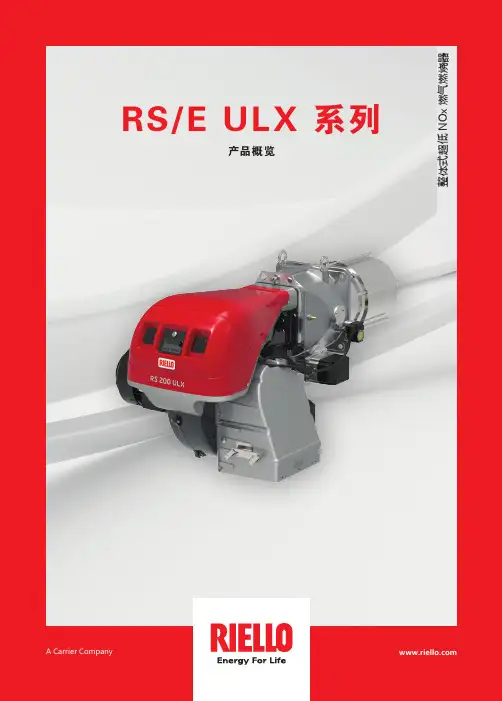
整体式超低 N O x 燃气燃烧器RS/E ULX 系列产品概览A Carrier Company RS/E ULX 系列 | 整体式超低 NOx 燃烧器氮氧化物排放能够低于40mg/Nm 3 @ 3,5% O 2(无 FGR, 需要合适的炉膛尺寸)对于一些应用,NO x 排放可以达到 30mg/Nm 3 @ 3.5% O 2 以下,但需要利雅路工程师确认。
超低 NOX整体式燃气燃烧器RS 68 - 510/E ULX 系列2RS 68/E ULXRS 120/E ULXRS 200/E ULXRS 310/E ULXRS 510/E ULX3RS/E ULX 系列 | 整体式超低 NOx 燃烧器为了满足日益增长的对极低 NOx 排放的要求,利雅路基于创新的 ULX 燃烧技术,开发了整体式的新系列燃烧器。
ULX 燃烧技术可以控制燃烧过程中产生的烟气量,从而达到最严格的排放限制。
在无需FGR装置以及从烟囱到燃烧器管道的情况下,ULX 燃烧技术可以使得氮氧化物排放低于40mg/Nm3 @3.5% O2 (无FGR,需要合适的炉膛尺寸)。
对于一些应用,NOx排放可以达到30mg/Nm3 @ 3.5% O2 以下,但需要利雅路工程师确认。
近年来,由于污染大幅度增加,全球各地特别是所有高度工业化国家,都对产品的性能、能效和排放物的减排更加关注。
ULX 燃烧技术—环境可持续发展的新里程碑新型 ULX 燃烧头采用燃气分级燃烧和废气内部再循环技术,极大地降低了 NOx 排放。
这种新型燃烧头体现了利雅路产品一贯的坚固性和可靠性。
集成的燃烧器数字控制系统,通过独立的伺服马达,可以控制每个出力点的空气和燃料比例,以达到非常低的 NOx 排放,同时使燃烧器保持极高的运行可靠性和安全性。
4>使用 ULX 燃烧技术后,无需再安装 FGR 系统通常所需要的管道系统,因此燃烧器的安装也更加方便。
>无需在锅炉房中安装管道,可以节省空间、时间和安装成本。
利雅路燃烧器中文说明书利雅路(Leverage)是一家专业生产户外用品的品牌,其燃烧器系列备受户外爱好者青睐。
在这里,我们为您详细介绍利雅路燃烧器的中文说明书,让您在使用中更加得心应手。
一、燃烧器的分类及用途燃烧器分为两种:火焰燃烧器和气体燃烧器。
火焰燃烧器适用于烧烤、点燃固体燃料等场景;而气体燃烧器则可以通过连接燃气罐使用,适用于露营、旅行等多种户外活动。
二、燃烧器的组件及操作方法1、组件利雅路燃烧器包含以下组件:火焰喷嘴、温度调节旋钮、火焰开关、点火器、燃气罐地支、燃气连接阀、燃气管路等。
2、操作方法①点火:打开燃气连接阀,按下点火器按钮,即可点燃燃气。
注意:在点燃之前确保燃气连接阀已经严密关闭好,以免发生危险。
②调节火力:利用温度调节旋钮可自由调节火焰大小,根据不同的需求进行调节。
③关闭:当使用完毕后,先关闭燃气连接阀,等待所有部件冷却后再收起即可。
三、维修及保养1、维修燃烧器为高温设备,维修时应当特别小心,以免造成危险。
若发生燃气漏气、火焰不稳定等情况,应及时停止使用,并按以下方法修理:①燃气漏气:立刻关掉燃气连接阀并打开燃烧器,让残留的燃气全部消失,确认消失后再进行修理。
②火焰不稳定:可能是火焰喷嘴堵塞或者燃气罐压力不足等原因导致,可以将火焰喷嘴拆下来清理或者更换新的燃气罐。
2、保养燃烧器的保养很简单,每次使用后清洗一下,移除灰尘和污垢即可。
使用过程中要注意防止火烧坏焦炭,影响燃烧效果。
四、购买及保修1、购买利雅路燃烧器可以在专业户外用品商店购买,根据不同的需求选择不同型号的燃烧器。
2、保修利雅路为燃烧器提供2年免费保修服务,若在保修期内发现燃烧器存在质量问题,可前往销售点或利雅路售后维修中心进行保修处理。
总结通过以上介绍,相信大家已经对利雅路燃烧器有了更加深入的了解。
在使用过程中,务必要注意安全,严格遵守使用说明,以免造成伤害。
在户外活动中,利雅路燃烧器为您提供舒适的烧烤体验和热饮服务,快来选购一款适合自己的利雅路燃烧器,享受美好的户外时光吧!。
2902967 (0)安装, 使用及维护说明书强制通风燃气燃烧器编码型号类型3761900RS5920 T1一段火运行29671中文目录1.燃烧器描述一段火强制通风燃气燃烧器.1.1燃烧器附件带绝热垫的法兰. . . . . . . . . . . . . . 1 将法兰安装到锅炉上的螺栓和螺母. . . . . . . . . . . . . .. 4法兰用螺栓螺母 . . . . . . . . . . . . . 1 7针插头 . . . . . . . . . . . . . . . . . . . . . . . . . . . . . . . . . .1马达启动电容. . . . . . . . . . . . . . . 11.燃烧器描述. . . . . . . . . . . . . . . . . . . . . . . 11.1燃烧器附件. . . . . . . . . . . . . . . . . . . . . . . 12.技术参数. . . . . . . . . . . . . . . . . . . . . . . . . 22.1技术参数. . . . . . . . . . . . . . . . . . . . . . . . . 22.2外观尺寸. . . . . . . . . . . . . . . . . . . . . . . . . 22.3工作范围. . . . . . . . . . . . . . . . . . . . . . . . . 33.安装. . . . . . . . . . . . . . . . . . . . . . . . . . . . 43.1锅炉安装. . . . . . . . . . . . . . . . . . . . . . . . . 43.2燃气阀组电气连接. . . . . . . . . . . . . . . . . . 43.3燃气管线. . . . . . . . . . . . . . . . . . . . . . . . . 53.4电极定位. . . . . . . . . . . . . . . . . . . . . . . . . 53.5电气连接. . . . . . . . . . . . . . . . . . . . . . . . .64.工作 . . . . . . . . . . . . . . . . . . . . . . . . . . . .74.1燃烧调节 . . . . . . . . . . . . . . . . . . . . . . . . .74.2燃烧头设置 . . . . . . . . . . . . . . . . . . . . . . .74.3风门挡板设置. . . . . . . . . . . . . . . . . . . . . .84.4燃烧检查 . . . . . . . . . . . . . . . . . . . . . . . . .84.5燃烧器启动程序. . . . . . . . . . . . . . . . . . . .94.6空气压力开关. . . . . . . . . . . . . . . . . . . . . .95.维护 . . . . . . . . . . . . . . . . . . . . . . . . . . . .96.故障 / 解决方法 . . . . . . . . . . . . . . . . . . . .101–压力开关2–燃气阀组6 孔插座 3–带 7孔插座的控制盒4–带锁定指示灯的复位按钮 5–燃烧头安装座6–压力测试点7–带绝热垫的法兰8–风门调整机构 9–风门伺服马达燃烧器保护等级为IP 40, EN 60529.CE 认证: 参照燃气应用标准 92/42/EEC; PIN 0085BM0114.燃烧器符合下列标准:EMC 89/336/EEC, 低电压 73/23/EEC, 机械 98/37/EEC 和效率 92/42/EEC.燃气阀组符合 EN 676.图. 1SW100129672中文2.技术参数2.1技术参数对燃用LPG 可选特殊附件.2.2外观尺寸类型920 T1燃烧器出力 (1)160–330 kW-137,600–283,800 kcal/h天然气 (品种 2)净热值:8–12 kWh/Nm 3=7000–10,340 kcal/Nm 3压力:min. 20 mbar-max.100 mbar电源 单相,230V ± 10% ~ 50Hz马达运行电流 2A -2750 rpm-289 rad/s马达启动电容8 μF点火变压器初级 230V / 0.2A –次级8 kV / 12 mA电功耗0.43 kW(1) 参考条件: 温度. 20°C - 大气压力 1013 mbar – 海拔 0 m .国家ITGBDE AT DK FRNLBEIE燃气种类II2H3B/P II2H3PII2E3B/PII2H3B/PII2H3B/PII2Er3P II2L3B/P I2E(R)B,I3P II2H3P 燃气压力G20H 2020–2020–––20G25L ––––––2525–G20E––20––20/25–20/25–29673中文2.3工作范围 (参照 EN 267)实验锅炉以上工作曲线是用符合 EN 676 标准的锅炉测量得到.商用锅炉如果锅炉是符合 EN 303 标准,且燃烧室尺寸与 EN 676图表所示相近时,则燃烧器与锅炉是匹配的. 如果锅炉不是符合 EN 303 标准,且燃烧室尺寸比 EN 676图表所示更小 ,请咨询生产厂家.燃气压力与燃烧器出力的关系在用热值为10kWh/m 3(8.570 kcal/m 3)的G20燃气和锅炉背压在0 mbar 进行检测时,燃烧器最大出力时燃烧器头部的压降为 9.9 mbar(M2, 参见 3.3, P. 5).130,000290,000kW燃烧器出力kcal/h2.40.80燃烧室压力 – m b a rD62311.6170,000210,000250,0004.03.2kW燃烧器出力kcal/h632燃烧头的燃气压力 – m b a rD6232475891029674中文3.安装燃烧器的安装必须符合当地法规和标准.3.1锅炉安装♦如有必要, 对绝热垫扩孔(3) (参见图. 3).♦ 用4个螺钉 (4) 和螺母 (2) 将法兰(5)安装到炉门(1)上,必须将绝热垫 (3) 放在中间,但应保持上部两颗螺钉中的一颗松动 (4) (参见图. 2).♦用螺钉 6将法兰 5固定到燃烧头上 紧固,拧紧松动的螺钉 4.注意.: 燃烧器具有可调的燃烧头长度 (A) (参见图. 4).总之, 要保证燃烧头完全穿过锅炉前墙.3.2燃气阀组电气连接燃气阀组连接电线可从左边或右边进入燃烧器,如所示.根据进入燃烧器的方向, 带压力测试点的电缆孔堵简易电缆孔堵 (2) 可能需要互换因此, 必须确认:电缆孔堵 (1)位置正确;气管位置应正确,以保证空气通畅关造成阻塞.注意如有必要,可将气管切到正确的长度图. 2SW1003212D46051图. 529675中文3.3燃气管线符合 EN 676的燃气阀组燃气阀组单独供货, 它的调整参考附带的说明书.3.4探针 - 点火电极定位, (参见图. 7)燃气阀组连接方式应用型号编码入口出口MBDLE 410 B013970549Rp 11/4法兰 3天然气 ≤ 200kW 和 LPG 160 – 330 kWMBDLE 412 B013970550Rp 11/4法兰 3天然气 ≤ 300 kW MBDLE 415 B013970558Rp 11/2法兰 3天然气> 300 kWD52091 –供气管2 –手动球阀 (3 –燃气压力表 (4 –过滤器5 –燃气压力开关6 –安全阀7 –稳压器8 –调节阀M1–供气压力测试点M2–阀组后压力测试点29676中文3.5电气连接S7003230V ~50Hz(230V - 0.5 A max.)风门伺服马达图. 8; 断开连接器., 移开所有组件后, 7针 地线 (H) 拧松螺钉 (A,)紧上螺钉(A).29677中文4.工作燃烧出力燃烧器点火应在低负荷状态下进行并不超过120kW.为了测量燃烧出力:–断开离子探针电缆上的连接插头(C ) (参见电气连接P. 6); 燃烧器点火并在安全时间 (3s)过后锁定 .–进行10 次点火并连续锁定.–从流量表中读出耗气量. 该耗气量应等于或小于以下数值: G20 (天然气 H) 为0.10 Nm 3 G25 (天然气 L)为0.10 Nm 3 G31 (LPG)为0.03 Nm 3.4.1燃烧调整(参见图. 9)根据燃烧器应用于锅炉上的效率标准92/42/EEC ,调试燃烧器必须参考锅炉的使用说明书, 这一工作包括调整烟气中的 CO 和 CO 2 含量,烟温及锅炉中的平均水温.要达到所需要的出力, 要选择正确的燃烧头设定值和风门设定值.燃烧器出厂时设定在最小出力.4.2燃烧头设定根据燃烧器的出力,通过顺时针和逆时针旋转 设定螺丝 (6) 来进行,直到标尺 (2) 上的刻度值与燃烧头座 (1)的外边缘对齐.在图9中的燃烧头的设定是对应于燃烧器出力为230 kW.可见燃烧头的设定值为 4,即 标尺上的刻度值与燃烧头座的外边缘对齐 .示例:燃烧器安装在 210 kW 的锅炉.考虑到锅炉效率为 90%,燃烧器出力应为 230 kW.如图所示,燃烧头应设在 刻度4.注意此图表仅供参考;为了获得较好的燃烧效果,建议可根据锅炉调整燃烧头的设定.kcal/hkW设定点D6235SW1004图. 929678中文拆卸燃烧头组件, (参见图. 9, P. 7)按下列顺序操作:拧下螺钉(7), 断开连接插头 (3 和 5), 拆下小管 (4) 并拧松螺钉 (10)后拆下燃烧头座(1).在拆卸时不要改变燃烧头的肘型弯座 的设定.重新安装燃烧头组件, (参见图. 9, P.7)注意-在安装燃烧头时, 拧紧螺钉 (7) (不要拧太紧); 然后用力矩扳手( 3 - 4 Nm )锁紧.-如上操作确保燃烧器在运行时螺钉处不会有燃气泄露.- 如压力测点 (11) 松动,应正确固定并确保燃烧头组件(1)外部的孔 (F)安装在正确的位置上.4.3风门设定, (参见图. 9, P.7)在拧松螺母 (9)后对调节螺钉进行调整(8).燃烧器停机时风门会自动关闭,除非烟囱处最大压降大于0.5 mbar.4.4燃烧状况检查建议根据燃气种类和下表来初步设定燃烧器:离子探针电流燃烧器正常运行时控制器所需最小离子探针电流为 5 µA.一般情况下离子探针电流会远大于该值, 故不必检查. 如需要检查时, 可打开离子探针连接插头 (C) (参见页 6)串入微安电流表, (参见图. 10).在首次点火时风门设定不应小于1.EN 676过量空气系数:最大输出λ ≤ 1.2–最小输出λ ≤ 1.3燃气最大CO 2含量(0 % O 2)设定CO 2 %CO mg/kWhNO x mg/kWh λ = 1.2λ = 1.3G 2011.79.79.0 ≤100≤170G 2511.59.58.8 ≤100 ≤170G 3014.011.610.7 ≤100 ≤230G 3113.711.410.5≤100≤23029679中文4.5燃烧器启动程序由控制盒上的信号灯指示燃烧器锁定(4, 图. 1, P .1).在燃烧器运行时火焰消失, 燃烧器在1秒内停机.4.6空气压力开关空气压力开关的调整应在燃烧器的上述调整工作完成后进行,此时应设在初始位置.当燃烧器工作在额定出力时, 缓慢顺时针加大设定值,直至燃烧器锁定.然后逆时针旋转刻度盘将设定值减少20%, 并检查燃烧器是否能正常启动.如燃烧器锁定,应再少量减少空气压力开关的设定值.燃烧器出厂时空气压力开关在初始位置.注意:作为标准条例, 空气压力开关调整要防止当空气压力达到设定的 80% 时排烟中的 CO 超过 1% (10,000 ppm).如要检查这一点,请在烟囱中插入烟气分析仪, 缓慢关闭风机的进气口 (例如用纸板) 并检查在排烟中的CO 超过 1%之前是否会锁定.5.维护燃烧器必须由授权的和有资格的技术人员按照当地法规和标准进行定期性的维护.维护对于燃烧器运行的可靠性是必要的,可避免燃料的过量消耗以及随之而来的污染.在进行维护清理之前,必须将系统的主电源开关关掉,以切断燃烧器的电源.基本的检查有:让燃烧器不间断地运行10分钟,按本说明书检查所有组件的设置 . 然后进行燃烧测试以检查以下各项: CO 2 (%)的含量 排烟温度 CO (ppm)的含量.296710中文6.故障 / 可能的解决方法下表所示是造成启动故障或燃烧器非正常运行等问题的原因及相应的解决方法.故障通常会造成控制盒 (4, 图. 1, P. 1)复位按钮键中的锁定指示灯亮.当锁定灯亮时,只有按复位按钮燃烧器才会重新启动,此后如果燃烧器运行正常,锁定可以归因于偶然故障.如果继续锁定,一定要查找原因,并加以解决.燃烧器启动故障故障可能原因解决方法当启动温控器闭合时,燃烧器不启动.没有电源供应.检查7针插头中的L1-N 线之间的电压是否存在.检查保险丝的状况.检查安全温控器是否锁定 .没有燃气供应.检查手动球阀是否打开 .检查阀组是否打开并且是否有短路 .燃气压力开关不闭合.调整.控制盒中的连接错误.检查并连接插头.空气压力开关在运行位置.更换压力开关.风门挡板卡住.检查电气连接.风门没全关所以燃烧器不点火: 检查.在预吹扫及点火阶段时燃烧器运行正常,但3秒后锁定.火线与零线接反.重接.没有地线或接地不良.确保接地良好.离子探针接地,离子探针未与火焰接触,离子探针与控制盒连线断开,与地短路 .检查离子探针的位置,如有必要可按本说明书进行设置.重新电气连接.更换损坏的接线.燃烧器点火延迟点火电极位置不对.按本说明书所示进行调整.空气太多.按说明书所示进行调整.阀门开度太小,燃气量不够.调整.296711中文运行中故障燃烧器锁定: – 火焰消失– 探针接地– 空气压力开关断开燃烧器停机: – 燃气压力开关断开燃烧器在预吹扫后因火焰故障而锁定.电磁阀过气量较小.检查管网压力/按说明书所示调整电磁阀.电磁阀损坏.更换.点火脉动或失败.检查接头.按说明书所示检查电极的位置.管道空气没有排净.燃气管道放散.燃烧器在预吹扫时锁定.空气压力开关不切换.压力开关故障,更换.空气压力过低, (燃烧头调整不当).火焰出现.阀门故障: 更换.压力测试点 (11, 图. 9, p 7) 位置不对. 按说明书 p 7, 节 4.2调整好位置.燃烧器不锁定,重复启动.主燃气压力接近于最低燃气压力开关所限定的数值.阀门开启后燃气压力的突降,从而引起压力开关的暂时断开.阀门立刻关闭,燃烧器停机.压力又升高,压力开关再次闭合,重复点火周期,该过程没有休止地进行.减小最低燃气压力开关的设定值.故障可能原因解决方法。
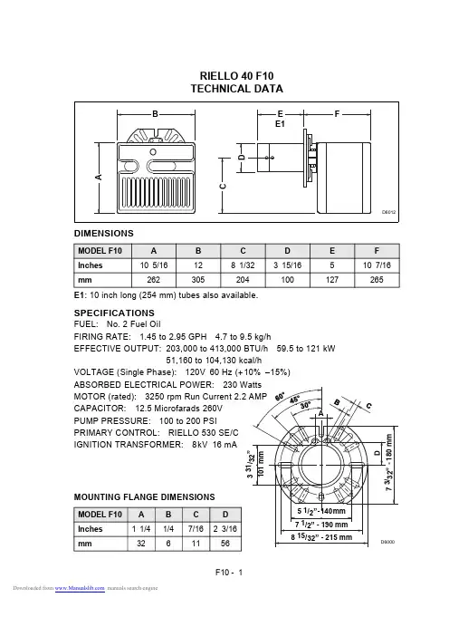
RIELLO 40 F10TECHNICAL DATADIMENSIONSF10 - 1F10 - 2OIL BURNER COMPONENTS IDENTIFICATIONF10BURNER COMPONENTSSERIAL NUMBER IDENTIFICATIONThe Riello 15 character serial number, example, 97 A 8511111 00025, is identified as follows: 97 = last two digits of the year of manufacture; A = BI-week of manufacture;8511111 = burner product code; 00025 = increment of 1 for each burner produced - spe-cific to product code - reset to zero each January 1st .INITIAL SET -UPA)Remove burner and air tube from cartons. Check parts list (inside cover) to ensureall parts are present.B)Remove burner cover by loosening the three screws securing it. Remove control box and air tube cover (see page 7).C)Remove drawer assembly from air tube, insert nozzle and set turbulator adjustment for specific input required (see pages 7 & 8), then set aside.D)Mount air tube to burner chassis (see page 3).1.Lockout indicator lamp and Reset button2.Primary control3.Primary control sub-base4.Pump pressure regulator adjustment screw5.Motor6.Capacitor7.Air adjustment fixing screws 8.Air shutter9.End cone10.Turbulator adjustment screw 11.Air tube cover 12.Coil13.Vacuum gauge connection port 14.Pressure gauge and bleeder port 15.Return fuel line port 16.Supply fuel line port 17.Adjustable collar18.Mounting flange with gasketBI-week of manufactureburner product codeYear of ManufactureSequence (97)(A)(851111)(00025)ASSEMBLY OF AIR TUBETO BURNER CHASSISThe air tube and drawer assembly are shipped in a carton separate from the burner chassis. Choose the proper air tube length to obtain the tube insertion for the specific installation.A) Remove the AIR TUBE and BURNER CHASSIS from their respective cartons.B) Remove the DRAWER ASSEMBLY (1) from inside the AIR TUBE by loosening the screw (2). Carefully pull the DRAWER ASSEMBLY out of the AIR TUBE, instal the required nozzle (see page 7) and set aside.C)Remove the two BOLTS (3) from FRONT PLATE (4) of the BURNER CHASSIS. Align the two holes on the AIR TUBE HOLDING PLATE (5) with the two holes left open on the BURNER CHASSIS FRONT PLATE when the BOLTS (3) were removed. Replace the BOLTS and finger tighten only. Re-install DRAWER ASSEMBLY into AIR TUBE. Tighten SCREW (2) securely (see page 7).D) Tighten the two bolts (3) securely.S7462MOUNTING THE BURNERTO THE BOILER OR FURNACEThere are three possible methods to mount the burner, depending on the individual application. These are:1)Universal flange bolted to Boiler/Furnace unit.2)Semi-flange collar bolted to Boiler/Furnace unit.3)Universal flange mounted to optional Pedestal mount, where flange-mounting direct to appliance is not possible. Pedestal kit must be ordered separately. METHOD 1 - UNIVERSAL MOUNTING FLANGEA)Insert the two BOLTS (1) into the UNIVERSAL MOUNTING FLANGE (10) from the flat side, ensuring the bolt heads are flush with the flat surface. Secure in place using two special CHROME NUTS (2) provided.F10 - 3F10 - 4B)Position the MOUNTING GASKET (3) between the flat surface of the UNIVERSAL MOUNTING FLANGE (10) and the appliance. Line up the holes in the UNIVERSAL MOUNTING FLANGE with the STUDS (4) on the appliance mounting plate and securely bolt the UNIVERSAL MOUNTING FLANGE to the plate.C)Secure the two semi-flanges of the ADJUSTABLE COLLAR (9) to the AIR TUBE using the two long BOLTS (6). Be sure that the ADJUSTABLE collar is properly positioned so the outside edge of the END CONE will be at least 1/4 inch (6.5 mm) back from the inside wall of the refractory of the combustion chamber (see dimension B at right). The measured length (A), is to include MOUNTING GASKET and FLANGE, if used.D)The burner may now be attached to the heating unit by inserting the AIR TUBE through the BURNER ACCESS HOLE (8)and into the appliance, making sure the BOLTS (1) line up with the two HOLES (5)in the ADJUSTABLE COLLAR. Secure the burner in place using two NUTS (7).A visual verification of the air tube insertion into the combustion chamber of the heating unit is suggested. DimensionB should be at least 1/4” (see drawing).NOTE: A suggested method for creating mounting bolt holes in the mounting gasket:Hold the gasket against the appliance mounting bolts using the mounting flange for proper positioning. Lightly tap the flange with a hammer to form the holes.S7461METHOD 2 - SEMI-FLANGE COLLARA)Follow item C from METHOD 1.B)Align the air tube and attached adjustable collar so air tube is centered in the burner access hole of the boiler/furnace unit. Mark the center of the two holes in the ADJUSTABLE COLLAR on to the front plate of the heating unit. Then drill 1/4 inch(6.5mm) holes through the front plate of the unit, using marks as a guide.C)Install two short BOLTS (1) through the front plate of the heating unit from the inside, and secure on the outside using the two special CHROME NUTS (2).D)Follow item D from METHOD 1.METHOD 3 - PEDESTAL MOUNTSecure the MOUNTING FLANGE to MOUNTING PEDESTAL using the hardware provided with the pedestal. Secure burner to MOUNTING FLANGE as in METHOD 1, items A, C and D.NOTE:It is suggested that the pedestal be anchored in position on the floor by installing brackets over the pedestal tube and securing brackets to the floor.Earth ground conductor terminal(black) wireter-(white)NsafetyS7454Do not connect either wire to theF10 - 5The burner may be controlled using either a DIRECT LINE VOLTAGE control circuit (120V AC 60 cycle) OR a LOW VOLTAGE control (24V AC 60 cycle) using a R8038A Honeywell switching relay or equivalent.Using the appropriate diagram below, make electrical connections to burner. All wiring must be done in accordance with existing electrical codes, both national and local. When all electrical connections have been made, the control box may be put back in place on the sub-base.F10 - 6NOZZLE PLACEMENTA)Determine the proper firing ratefor the boiler or furnace unit, consid-ering the specific application, thenuse the Burner Set-up chart on page12 to select the proper nozzle andpump pressure to obtain the requiredinput from the burner.B)Remove the NOZZLE ADAPTER(2) from the DRAWER ASSEMBLY byloosening the SCREW (1).S7459C)Insert the proper NOZZLE into theNOZZLE ADAPTER and tighten securely (Do not overtighten).D)Replace adapter, with nozzle installed, into drawer assembly and secure with screw (1).INSERTION/REMOVAL OF DRAWER ASSEMBLYA)To remove drawer assembly, loosen SCREW (3), then unplug CONTROL BOX (1) by carefully pulling it back and then up.B)Remove the AIR TUBE COVER PLATE (5) by loosening the two retaining SCREWS (4).C)Loosen SCREW (2), then slide the complete drawer assembly out of the combustion head as shown.D)To insert drawer assembly, reverse the procedure in items A to C above, then attach fuel line to the pump.S7460F10 - 7F10 - 8ELECTRODE SETTINGTURBULATOR SETTINGA)Loosen NUT (1), then turn SCREW (2) until the INDEX MARKER (3) is aligned with the correct index number as per the Burner Set-up chart, on page 12.B)Retighten the RETAINING NUT (1).NOTE:Zero and five are scale indica-tors only. From left to right, the first line is 5 and the last line 0.OIL LINE CONNECTIONSThis burner is shipped with the oil pump set to operate on a single line system. To operate on a two line system the by-pass plug must be installed.Warning: Do not operate a single line system with the by-pass plug installed.Operating a single line system with the by-pass plug installed will result in damage to the pump shaft seal.Note: Pump pressure must be set at time of burner start-up.A pressure gauge is attached to the PRESSURE PORT (8) for pressure readings. Two PIPE CONNECTORS (5) are supplied with the burner for connection to either a single or a two-pipe system. Also supplied are two ADAPTORS (3), two female 1/4” NPT, to adapt oil lines to burner pipe connectors. All pump port threads are British Parallel Thread design. Direct connection of NPT threads to the pump will damage the pump body.Riello manometers and vacuum gauges do not require any adaptors, and can be safely connected to the pump ports. An NPT (metric) adapter must be used when connecting other gauge models.SINGLE LINE (GRAVITY FEED SYSTEM)A)The burner is shipped configured for use in single line applications. No changes to the oil pump are required for use in single line applications.NOTE: If the pump cover (1) is removed for any reason, be sure the O-ring (2), is properly seated in the pump cover (1) before re-attaching the pump cover to the pump housing.B)Connect the pipe connector to the SUPPLY PORT (6) of the pump. Attach the required piping to this pipe connector. Be sure that the plug in the RETURN PORT (9) is tightened securely.F10 - 9TWO LINE (LIFT SYSTEM)A)If a two line system is required, install the By-pass plug (4) provided. The by-pass plug is installed in the return port (9) of the pump. A 2.5 mm hexagonal key provided with the by pass plug is to be used to install the plug. DO NOT use an inch size hexagonal key, damage to the by-pass plug may result. When operating on a two line system, supply and return lines should be the same diameter and both should extend to the same depth inside the fuel tank. Be sure there are no air leaks or blockages in the piping system.Any obstructions in the return line will cause failure of the pump shaft seal. Do not exceed the pipe lengths indicated in the tables.To install the by-pass plug:1) Remove the return plug (9).2) Install the by-pass plug (4) using the 2.5 mm hexagonal key.B)Attach the two PIPE CONNECTORS (5) to the pump SUPPLY and pump RETURN PORTS (6 and 9). Attach the required piping to these two pipe connectors using the NPT/METRIC ADAPTERS that are supplied with the burner.WARNING:Pipe dope or Teflon tape are NOT to be used on any direct oil con-nection to the fuel pump.WARNING:The height “P” in Pipe Length charts on page 9 and 10 should not exceed 13feet (4 m).WARNING:The vacuum should not exceed 11.44 inches of mercury. IMPORTANT:An external, appropriately listed and certified oil filter must be placed in the fuel line between the fuel tank and the burner pump.F10 - 10。
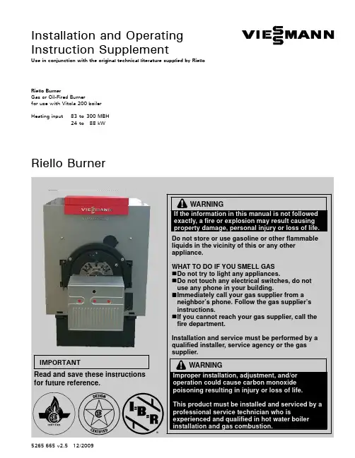
Installation and Operating Instruction SupplementUse in conjunction with the original technical literature supplied by Riello Riello BurnerGas or Oil-Fired Burnerfor use with Vitola200boilerHeating input83to300MBH24to88kWRiello BurnerIf theexactly,IMPORTANTRead and save these instructionsfor future reference.5265665v2.512/2009Safety,Installation and Warranty Requirements2Please ensure that this manual is read and understood before commencing installation.Failure to comply with the issues listed below and details printed in this manual can cause product/property damage ,severe personal injury ,and/or loss of life .Ensure all requirements below are understood and fulfilled (including detailed information found in manual subsections).Each of the following issues is very important and is discussed in detail in the boiler technical literature.Ensure that the installation complies fully and completely with all requirements set out in the boiler technical literature.H Licensed professional heating contractorThe installation,adjustment,service,and maintenance of this equipment must be performed by a licensed professional heating contractor."Please see section entitled “Important Regulatory and InstallationRequirements”.H Product documentationRead all applicable documentation before commencing installation.Store documentation near boiler in a readily accessible location for reference in the future by service personnel."For a listing of applicable literature,please see section entitled “Important Regulatory andInstallation Requirements”.H Advice to ownerOnce the installation work iscomplete,the heating contractor must familiarize the systemoperator/ultimate owner with all equipment,as well as safetyprecautions/requirements,shut-down procedure,and the need forprofessional service annually before the heating season begins.H Contaminated airAir contaminated by chemicals can cause by-products in the combustion process which are poisonous to inhabitants and destructive to Viessmann equipment.H Carbon monoxideImproper installation,adjustment,service and/or maintenance can cause flue products to flow into living space.Flue products contain poisonous carbon monoxide gas.H Fresh airThis equipment requires fresh air for safe operation and must be installed ensuring provisions for adequate combustion and ventilation air exist.H Equipment ventingNever operate boiler without an installed venting system .H WarrantyInformation contained in this and related product documentation must be read and followed.Failure to do so renders warranty null and void.5265665v 2.5Do not chlorine near the Never adequate air.AllContents3PageSafety Important Regulatory and Installation Requirements4....Set-upProduct Delivery 4.......................................................................Mounting Burner5......................................................................Burner Set-up -Gas 6.................................................................Burner Set-up -Oil10...................................................................Oil Cartridge Assembly 13...........................................................Burner Set-up -Gas and Oil13..................................................Start-up/AppendixStart-up Information 14................................................................Technical Data 15..........................................................................Wiring Diagram18.........................................................................Maintenance Record20...............................................................OperationLighting Instructions23...............................................................5265665v 2.5Safety4Take note of all symbols and notations intended to draw attention to potential hazards or important productinformation.Set-up5Installation1.Remove burner from carton.The universal mounting flange has been installed on the burner at the factory.2.Mount burner as shown in Figs.1and 2.5265665v 2.5Fig.1Installing burnerFig.2Securing burner flange to combustion chamberdoorSet-up6InstallationThe gas train may be mounted on the left or on the right side of burner.G200burners have a ½”NPT female gas connection.G400burners have a ¾”NPT female gas connection.Gas trainNG flow pressure:min. 4.0”w.c.max.10.5”w.c.LP flow pressure:min.8.0”w.c.max.13.0“w.c.Legend (Fig.3)Gas supply and gas flow direction Gas shut-off valve (field supplied)Gas supply pressure test point (field supplied)Gas train pipe diameter(s)Burner G200½”NPT Burner G400¾”NPTMaxitrol RV52with RV5210-13(brown spring 1.0to 3.5”w.c.)gas appliance pressure regulator Honeywell gas solenoid valve V8295N.C.(24V operated)Dungs MVD-LE model 200G200=MVD-LE 205/6(24V)G400=MVD-LE 207/6(24V)Gas burner manifold test pointGas piping pressure testThe burner and its gas connection must be leak-tested before placing theboiler/burner combination in operation.The burner and its individual shut-off valve must be disconnected from the gas supply piping system during any pressure testing of that system atpressures in excess of 0.5psig/3.5kPa.Unions and manifold have been factory-tested.Leak test must be repeated during initial operation of burner by heating contractor.Never check for gas leaks with an open e approved spray liquid or soap water solution for bubble test.5265665v 2.5IMPORTANTFig.3Gas train Field Supplied Viessmann Supplied"Set-up7Flow adjustment cap Pan head screwSealing cap/adjustment cap toolBurner manifold gas pressure adjustmentThe burner manifold gas pressuresettings must be performed using the RV52gas appliance regulator only .In the event of low gas supply pressure,increase gas supply pressure using the RV52gas regulator to required minimum gas supply pressure.Operating and Installation Instructions for gas train components (supplied)No preliminary adjustments required for Honeywell V8295N.C.gas solenoid valve.Adjustment steps1.Attach manometer to burner manifoldtest point (combustion head ).2.Start up burner and observe.3.Wait until burner has stabilized to adjust burner manifold pressure using the RV52gas appliance regulator,and set to required burner manifold pressure setting.Use factory default settings (pages 15and 16)as starting point only.4.To adjust the initial lift gas pressure remove sealing cap,exposing the lift adjustment knob,turn over cap,adjust knob to “+”to increase the start pressure and set to approx.0.7to 0.9“w.c.(manifold pressure).Factory default setting is set to 100%full flow.5.Restart appliance at least three times to finalize gas manifold setting and to determine a smooth ignition.6.If burner fails to ignite or ignition is delayed or hard,one or more of the following corrective actions may be required:H Adjust initial gas pressure settingon Dungs gas valve.H Ignition electrode and/or ionization (flame)rod is not set withinspecified range,adjust setting by referring to original Installation Instructions of Riello burner.5265665v 2.5Fig.4MVD-LE valve,sideviewFig.5MVD-LE valve,top viewIMPORTANTIMPORTANTIMPORTANTSet-up8Verifying input of gas boilersNatural gas burners must have gas input clocked using the gas meter.Ensure there is no gas flowing through the meter other than to the gas-fired boiler being checked.See pages 15and 16for gas flow rate and values for time (in seconds)for clocking gas meter.Clock at least 10revolutions on a one ft 3gas meter dial and divide time by 10.The value arrived at should be the same as shown on pages 15and 16.If necessary,manifold pressure must be adjusted to make sure burner is firing at nominal input.Do not exceed gas input stated on rating plate.Turn adjustment screw on gas pressure regulator (RV52)clockwise to increase gas flow,and counterclockwise to decrease gas flow (as per instructions on the previous page).If checking gas input with a manometer only use manifold pressures given in manual as a starting point,and use combustion instruments to ensure safe and efficient combustion values.Be sure to turn gas off before attaching or removing pressure taps.All plugs removed for the purpose of gas pressure measurements must be replaced and leak-tested after Replacement of 24V gas valveUse only replacement gas valves from Viessmann Manufacturing.The 24VAC Dungs ¾”MVD-LE 207/6and ½”MVD-LE 205/6direct spark valves are special valves designed to operate at the low manifold pressures required by the Riello burner for both natural and propane gas.Do not use other gas valve unless specified by Viessmann.Field measured combustion resultsUse the combustion data label packed with the gas burner to record fieldmeasured combustion results and affix label to gas burner.Adjustment data tag ANSI Z21-17b-1994Input:C.F.H.Manifold pressure Air damper Air/gas ratio No.Flue gas temp.O 2level:%CO 2level:ppm DateCompleted by Installing contractorIt is necessary to follow all safety information in the Riello technical literature as well as all other OEM component instructions shipped with this manual.The Viessmann factory settings are an initial guide to be verified or changed by the installer based on field measured combustion results.The burner settings arrived at during field measurements may be different from the generalizedconversion burner settings given in the Riello technical literature.5265665v 2.5IMPORTANTEach Riello manifold gas valve,IMPORTANTSet-up9Summary of changes to original Rielloburner Note the following constructiondifferences between the general Riello conversion burner and Riello burnersupplied for use on the Vitola boiler.N200and P200burners for use with Vitola 200VB2-18to VB2-40The 40-(N,P)200gas burners when supplied by Viessmann for VB2-18and -22are constructedwith drawer assembly diaphragm installed in the combustion head assembly for natural gas andpropane.SleeveDrawer assembly diaphragm OrificeThe main gas orifice for natural gas is changed from the 2.0mm orificenormally supplied with a 40-(N,P)200aftermarket conversion burner to that stated in the table below.The differences in orifice size for the VB2-18,-22cause the manifoldpressure adjustment information in the Riello 40-(N,P)200manual to be not e the manifold pressures in this manual as a starting point for burner adjustment for the VB2-18,-22.Do not change orifice,diaphragm or sleeve-combination.Contact the Viessmann Technical Department.Burner Model Model No.Boiler G200VB2-18G200VB2-22G200VB2-33G200VB2-40OrificeLP1.3 1.3 1.3 1.3SleeveNG n.a.installed installed n.a.LPinstalled installed installedinstalledDiaphragmNG installed installed n.a.n.a.LPinstalledinstalledn.a.n.a.n.a.=not applicable5265665v 2.5IMPORTANTH:15.8mm W:19.5mmN88mm 19m mSet-up10The oil burner is provided with its own oil filter and built-in flow check valve.The flow check valve is located in the return,and a manual shut-off is located in the supply.One-pipe systems1.Connect as shown in Fig.6.5265665v 2.5Fig.6Connection to a one-pipesystemSet-up112.Mount filter support bracket either on the side of the boiler (Fig.7)or on the front of the boiler (Fig.8).3.Mount filter and check valve assembly to mounting bracket (Fig.9).Filter is disposable type and must be replaced with the filter cartridge supplied by Viessmann.5265665v 2.5Fig.7Side-mounting support bracketFig.8Front-mounting supportbracketFig.9Mounting filter and check valveassemblySet-up12oil line from tankto oil pump on burner from oil pump on burner recirculation to filter4.Connect flexible oil lines to the filter check valve assembly.See Fig.10.Red:supply (connection with the red manual valve)Blue:return (connection with the check valve).The Riello burner shipped by Viessmann comes with the bypass plug alreadyinstalled,ready for two-pipe connection.For a one-pipe system (gravity system where the oil tank is above the burner)use the copper tee provided.This tee converts the two-pipe system to a one-pipe system.The oil not used by the pump recirculates into the supply line.Pipe sealant must be used on the threaded ends of the flare fittings which join the copper tee to the filter check valve assembly .5.Install tee as shown in Fig.11.5265665v 2.5Fig.10Connect oil supply and returnlinesFig.11Converting two-pipe system to one-pipe systemSet-up131.Check that all surfaces are clean before installing new O-ring supplied with replacement filter cartridge.2.Set O-ring in place and mount new filter cartridge.3.Attach clear plastic cup and tighten brass nut.Never tighten brass nut with a tool;hand tighten only.Cap and O-ring mightdeform and leak air.The flare adaptors are tapped 3/8”BSP (British straight pipe)at the factory.Replacement flare adaptors must be ordered from Viessmann.Do not use 3/8”NPT flare adaptor as replacement.Burner Set-up -Gas and OilRefer to Riello instructions for adequatefuel supply pipe sizing and sequence of burner operation.Ensure an adequate supply of fresh combustion and ventilation air for safe operation.Refer to codes mentioned on page 4.Electrical connections1.Run the plug-in connector cable of the Vitotronic control down behind the front panel of the boiler and out through the wire strain relief as per the boiler installation instructions (Electrical Connections).2.Connect the female plug of the burner to the male plug of the Vitotronic control.See Fig.13.Installation Instructions Riello gas or oil burner5265665v 2.5Fig.12Oil cartridge assemblyIMPORTANTIMPORTANTWhen mounted,cup.Check IMPORTANTFig.13The quick-connect plug-insystemStart-up Information14Boiler start-upStart-up/Service Instructionsof boiler,as well as literature of burner,burner test sheet and control literature.Combustion analysisThis gas or oil burner requires combustion measurements to beperformed at the final installation site by a licensed heating contractor toverify factory settings,or to be used as a guide in changing burner settings to suit local conditions.Examples of local conditions which influence combustion results include:weather conditions,length of horizontal vent pipe,diameter and height of the chimney,side wall venting (power vent),altitude above sea level,quality and heating value of gas or oil used,maximum number of other fuel burning appliances running at the same time.These conditions affect the burnerset-up.The burner must be adjusted for acceptable combustion results under local conditions of the installation.When the boiler is fired for the first time,the ceramic fiber insulation at the back of the combustion chamber door will require ½to 1hour of firing time to “cure”.An odor may occur during this time.Final measurements of CO must be done only after the “cure”is complete.Combustion measurements (CO 2,stack temperature,draft and CO)are taken in the flue pipe between boiler and barometric draft regulator beforedilution air (see the installation manual).Overfire draft is measured at thecombustion chamber observation port opening.The expected CO 2products of combustion are printed below.These values are based on average results -slightly higher or lower values may be suitable depending on installation conditions.Fuel NG LP Oil CO 29.5to 10.2%10.0to 11.5%11.0to 13.0%The CO concentration should be asshown on the Viessmann quality control burner test results.If the COconcentration is above 50ppm,then measures should be taken to decrease concentration to a value below 50ppm.Steps to be taken include:ensuring sufficient supply of combustion air,adjusting air gate settings,ensuring chimney and vent are correct and meet safety codes,verifying boiler input and burner settings,replacing any defective part on burner,contactingmanufacturer’s technical sales representative for assistance.5265665v 2.5IMPORTANTTest port for combustion analysis equipmentDO NOT CRANKCASE OIL CONTAINING Do not controls.DO NOT BURNER ACCUMULATED,Appendix15Natural gasThe above specifications are for 0-2000ft.above sea level.Burner test resultsThe indicated values for manifold and air gate settings are the result of production line testing under ideal conditions.Final burner adjustment to suit local field conditions is necessary for safe operation.Observe the stated minimum and maximum supply gas pressures.Exposing the burner gas train to supply pressures other than the stated values can cause unsafe conditions.Viessmann strongly recommends the installation of an approved type CO detector in the vicinity of any gas burning equipment.Observe national and/or local code requirements.If in doubt consult your local gas company.Verification of resultsThe burner adjustment values indicated serve as a starting point bustion results must be field verified using properly calibratedBacharach or equivalent instruments.Each burner is certified for one input only.Do not overfire or underfire burner.Technical dataFuel natural gas ...........................................Averageheating value 1000MBH/ft 3...................Inlet gas pressuremin.4.0”w.c............max.10.5”w.c.Draft regulatorVB2-18to -40MG16”...........................VB2-50to -63MG17”...........................Overfire draft +0.01”w.c......................Max.breeching draft -0.02”w.c...........INPUT =3600/T x 1000where T =TIME (sec.)for 1ft 3natural gas INPUT =(3600x 0.01x 1000x 35.31)/T where T =TIME (sec.)for 0.01m 3natural gas5265665v 2.5Do not Factory changed IMPORTANTAppendix16Liquid propaneThe above specifications are for 0-2000ft.above sea level.Burner test resultsThe indicated values for manifold and air gate settings are the result of production line testing under ideal conditions.Final burner adjustment to suit local field conditions is necessary for safe operation.Observe the stated minimum and maximum supply gas pressures.Exposing the burner gas train to supply pressures other than the stated values can cause unsafe conditions.Viessmann strongly recommends the installation of an approved type CO detector in the vicinity of any gas burning equipment.Observe national and/or local code requirements.If in doubt consult your local LP company.Verification of resultsThe burner adjustment values indicated serve as a starting point bustion results must be field verified using properly calibratedBacharach or equivalent instruments.Each burner is certified for one input only.Do not overfire or underfire burner.Technical dataFuel propane gas .........................................Averageheating value 2500MBH/ft 3...................Inlet gas pressuremin.8”w.c............max.13”w.c.Draft regulatorVB2-18to -40MG16”...............VB2-50to -63MG17”...............Overfire draft +0.01”w.c....................Max.breeching draft -0.02”w.c......INPUT =3600/T x 2500where T =TIME (sec.)for 1ft 3propane gas INPUT =(3600x 0.01x 2500x 35.31)/T where T =TIME (sec.)for 0.01m 3propane gas5265665v 2.5Do not Factory changed IMPORTANTAppendixFig.14Air tube insertion (VB2-18,-22,-33)a asemi-flange(VB2-40,-50,-63)17Fuel oil No.2In multiple-boiler installations,a booster pump may be required.F10burners for use with Vitola 200VB2-50,VB2-63The F10as supplied by Viessmann uses the 10”long tube and a specialturbulator disc and end cone unique to Viessmann.Order replacements from Viessmann only.5265665v 2.5IMPORTANTAppendix18Vitotronic boiler controlRiello burner120VAC,60Hz,2.5ABurner plug-in connector(male and female)Primary control connections;connect blue wire to the followingterminal on the control box:Fuel NG LP OilTerminal776Motorized air damper(gas burneronly)Low water cut-off(field supplied,if required)Heating system ON/OFF switch120VAC,installer must provide15A overcurrent protectionReceptacle(site)120VACInstall the boiler as described in itstechnical documentation beforeinstalling or operating the burner.120VAC is supplied to burner viaplug-in connector.Do not connectadditional120VAC to burner.If any of the original wires as suppliedwith the appliance must be replaced,replace with221°F/105°C rated or itsequivalent.Minimum size18AWG.5265665v2.5LWCOTurn offsupplyContactLabelwhencan causeAppendix191.Install blocked vent switch(see enclosed FieldControls WMO-1Installation Instructions).2.Run BX cable (armored cable)or any other approved wire (required by local authorities having jurisdiction)from WMO-1switch to burner e nominal ½”electrical knockout provided on Riello plate forconnectors.If necessary,relocate wiring harness strain relief to other electrical opening provided.3.Disconnect black wire (BK)of 7-poleplug from oil burner primary control base.4.Rewire (wire nut included)the black wire (BK)through WMO-1safety switch and back to terminal “L”of the oil burner primary control.52Legend BK Black BU Blue GN Green RD Red WHWhiteFor use Do not sidewallAppendix20Service binder1.File all Parts Lists,Operating and Service Instructions in the Service Binder.2.Install a protective hanging case near the boiler and store the Service Binder in this location.MaintenanceBefore each heating season begins,have the following service and maintenance done by a licensed,professional heating contractor:1.Boiler heat exchanger inspected and cleaned.2.Vent system inspected fordeterioration,leaks,corrosion,proper draft,and proper operation.Check vent system for compliance withlocal and national code requirements.Repair or replace as required.3.Burner checked and,if necessary,adjusted for proper combustion and operation.Check for adequate supply of fresh outside combustion and ventilation air.5265665v 2.5Neglecting maintenance operation.Appendix215265665v 2.5Appendix225 2 6 5 6 6 5 v 2 . 5OperationManual gas shutoffOpenClosedTO1.Set thermostat or other operating controlsetting.2.Turn off all electric power to the applianceis to be performed.3.Close main gas shut-off valve.23Viessmann Manufacturing Company Inc.750McMurray RoadWaterloo,Ontario •N2V 2G5•CanadaTel.(519)885-6300•Fax (519)885-0887www.viessmann.ca •*****************Viessmann Manufacturing Company (U.S.)Inc.45Access RoadWarwick,Rhode Island •02886•USATel.(401)732-0667•Fax (401)732-0590 •*********************24Conversion Table H “w.c.x 2.54=mbar H mbar x 0.394=“w.c.H kW x 3413=Btu H bar x 14.5=psigH kg x 0.289=USG (#2oil)H BHP x 9.8=kW H BHP x 33779=Btu H m x 3.28=ft.H m 3x 35.3=ft.3H kcal x 3968=BtuH Cal value NG =950-1050Btu/ft.3H Cal value LP =2450-2500Btu/ft.3H Motor kW x 1.31=Motor HPNG Natural Gas LP Liquid PropaneQuick Reference °C °F -40-40-35-31-25-13-20-4-180-16+3-14+7-12+10-10+14-9+16-8+18-7+19-6+21-5+23-4+25-3+27-2+28-1+300+32+1+34+2+36+3+37+4+39+5+41+6+43+7+45+8+46+9+48+10+50+12+54+14+57+16+61+18+64+20+68+25+77+30+86+35+95+40+104+50+122+60+140+70+158+80+176+90+194+100+212+110+2305265665v 2.5T e c h n i c a l i n f o r m a t i o n s u b j e c t t o c h a n g e w i t h o u t n o t i c e .。
强制通风燃气燃烧器平滑二段火或比例调节运行代码型号类型3753883GAS 8 P/M538 T80 3753884GAS 8 P/M538 T80 3754083GAS 9 P/M540 T80 3754084GAS 9 P/M540 T80 3754185GAS 10 P/M541 T80 3754186GAS 10 P/M541 T80 3754187GAS 10 P/M541 T80 3754188GAS 10 P/M541 T80目录 页码1概述. . . . . . . . . . . . . . . . . . . . . . . . . . . . . . . . . . . . . . . . . . . . . . .31.1技术参数 . . . . . . . . . . . . . . . . . . . . . . . . . . . . . . . . . . . . . . . . . . .31.2可选型号 . . . . . . . . . . . . . . . . . . . . . . . . . . . . . . . . . . . . . . . . . . .31.3燃烧器描述 . . . . . . . . . . . . . . . . . . . . . . . . . . . . . . . . . . . . . . . . .41.4包装 重量. . . . . . . . . . . . . . . . . . . . . . . . . . . . . . . . . . . . . . . . . . .41.5最大尺寸 . . . . . . . . . . . . . . . . . . . . . . . . . . . . . . . . . . . . . . . . . . .41.6标准配件 . . . . . . . . . . . . . . . . . . . . . . . . . . . . . . . . . . . . . . . . . . .41.7附件. . . . . . . . . . . . . . . . . . . . . . . . . . . . . . . . . . . . . . . . . . . . . . .51.8出力图. . . . . . . . . . . . . . . . . . . . . . . . . . . . . . . . . . . . . . . . . . . . .61.9测试锅炉 . . . . . . . . . . . . . . . . . . . . . . . . . . . . . . . . . . . . . . . . . . .61.10燃气压力 . . . . . . . . . . . . . . . . . . . . . . . . . . . . . . . . . . . . . . . . . . .62安装. . . . . . . . . . . . . . . . . . . . . . . . . . . . . . . . . . . . . . . . . . . . . . .72.1锅炉板. . . . . . . . . . . . . . . . . . . . . . . . . . . . . . . . . . . . . . . . . . . . .72.2燃烧头长度 . . . . . . . . . . . . . . . . . . . . . . . . . . . . . . . . . . . . . . . . .72.3将燃烧器固定在锅炉上 . . . . . . . . . . . . . . . . . . . . . . . . . . . . . . . .82.4设置燃烧头 . . . . . . . . . . . . . . . . . . . . . . . . . . . . . . . . . . . . . . . . .82.5燃气管路 . . . . . . . . . . . . . . . . . . . . . . . . . . . . . . . . . . . . . . . . . . .92.6电气设备,工厂设置 . . . . . . . . . . . . . . . . . . . . . . . . . . . . . . . . .102.7电气设备,安装人员设置. . . . . . . . . . . . . . . . . . . . . . . . . . . . . .103点火前的控制与校准 . . . . . . . . . . . . . . . . . . . . . . . . . . . . . . . . .133.1锅炉. . . . . . . . . . . . . . . . . . . . . . . . . . . . . . . . . . . . . . . . . . . . . .133.2燃气管道 . . . . . . . . . . . . . . . . . . . . . . . . . . . . . . . . . . . . . . . . . .133.3助燃空气 . . . . . . . . . . . . . . . . . . . . . . . . . . . . . . . . . . . . . . . . . .143.4电气系统 . . . . . . . . . . . . . . . . . . . . . . . . . . . . . . . . . . . . . . . . . .143.5燃烧器启动 . . . . . . . . . . . . . . . . . . . . . . . . . . . . . . . . . . . . . . . .144燃烧器点火 . . . . . . . . . . . . . . . . . . . . . . . . . . . . . . . . . . . . . . . .155燃烧器校准 . . . . . . . . . . . . . . . . . . . . . . . . . . . . . . . . . . . . . . . .155.1设置燃烧头 . . . . . . . . . . . . . . . . . . . . . . . . . . . . . . . . . . . . . . . .155.2设置伺服马达. . . . . . . . . . . . . . . . . . . . . . . . . . . . . . . . . . . . . . .165.3设置燃气压力. . . . . . . . . . . . . . . . . . . . . . . . . . . . . . . . . . . . . . .175.4设置燃烧器出力. . . . . . . . . . . . . . . . . . . . . . . . . . . . . . . . . . . . .175.4.1设置最大出力. . . . . . . . . . . . . . . . . . . . . . . . . . . . . . . . . . . . . . .185.4.2设置最小出力. . . . . . . . . . . . . . . . . . . . . . . . . . . . . . . . . . . . . . .195.4.3设置中间出力. . . . . . . . . . . . . . . . . . . . . . . . . . . . . . . . . . . . . . .205.5设置空气压力开关. . . . . . . . . . . . . . . . . . . . . . . . . . . . . . . . . . .205.6设置最大燃气压力开关 . . . . . . . . . . . . . . . . . . . . . . . . . . . . . . .205.7设置最低燃气压力开关 . . . . . . . . . . . . . . . . . . . . . . . . . . . . . . .205.8设置燃烧 . . . . . . . . . . . . . . . . . . . . . . . . . . . . . . . . . . . . . . . . . .215.9火焰监测 . . . . . . . . . . . . . . . . . . . . . . . . . . . . . . . . . . . . . . . . . .216运行. . . . . . . . . . . . . . . . . . . . . . . . . . . . . . . . . . . . . . . . . . . . . .227最终控制装置. . . . . . . . . . . . . . . . . . . . . . . . . . . . . . . . . . . . . . .238燃气流量测量. . . . . . . . . . . . . . . . . . . . . . . . . . . . . . . . . . . . . . .239燃烧器不运行. . . . . . . . . . . . . . . . . . . . . . . . . . . . . . . . . . . . . . .2310维护. . . . . . . . . . . . . . . . . . . . . . . . . . . . . . . . . . . . . . . . . . . . . .2511附表. . . . . . . . . . . . . . . . . . . . . . . . . . . . . . . . . . . . . . . . . . . . . .26注意事项注意事项::在文本中所提及的图形标识按如下说明:1)(A)= 图(A)的第1部分,与文本的同页;1)(A)p.4= 图(A)的第1部分,页码为4;1)= 所提及最后一张图的第1部分。
利雅路燃烧器安装说明标准化管理处编码[BBX968T-XBB8968-NNJ668-MM9N]
一、喷嘴的安装:
1、核对喷嘴型号,每个数值的油耗为4.2KG/H。
2、取下末端锥筒
3、取下风量调节筒
4、取下稳焰盘组件
5、取下塑料塞子后,用16mm扳手将喷嘴进行安装。
请勿使用任何密封材料,注意不要损坏喷嘴的密封垫。
安装时喷嘴必须拧到位,但不要拧脱扣。
6、点火装置调节(一般情况不需要调节)
二、燃烧头调节(一般不需要调节)
根据出力大小,按说明书提供图表调整刻度盘至相应位置
三、油路安装
1、按照箭头方向安装进油管和回油管,过滤器安装在进油管路上。
四、电气连接
1、交流220V供电,接X7插头。
2、公司一般通过控制电源通断控制燃烧器工作,需将X7插头T1、T2端子短接。
3、如需二段火运行,需将X4插头T6、T8端子短接。
注:小型燃烧机(G20)接线端子⊙为故障输出的指示灯接线端子,千万不要接地。
五、启动
1、检查油路、电气连接是否正确。
2、松开油泵下的螺栓V,排除泵中的空气。
3、启动燃烧器,油泵方向必须与所标示一致。
如果螺栓V处有油漏出,油泵注油成功。
关闭燃烧器,拧紧螺栓。
六、烟度调节
黑烟为燃烧不充分,需调大风门。
白烟为风量过大,需调小风门。
二段火工作时的风门调节一般调整一段火风门是燃烧机顺利点火为宜,调整二段火风门至要求烟度。
调整完成后,拧紧防活动螺丝。
利雅路燃烧器中文说明书尊敬的用户:感谢您选择利雅路燃烧器。
为了确保您能够安全、正确地使用本燃烧器,并充分发挥其性能,在使用前请仔细阅读本说明书。
一、产品概述利雅路燃烧器是一种高效、可靠的热能设备,广泛应用于工业、商业和民用领域。
它采用先进的燃烧技术,能够将燃料(如天然气、液化气、柴油等)转化为热能,为您的生产和生活提供稳定的热源。
二、主要技术参数1、型号:不同型号的燃烧器具有不同的功率和适用范围,请根据您的实际需求选择合适的型号。
2、燃料类型:可适应多种燃料,如天然气、液化气、柴油等。
3、功率范围:从_____千瓦到_____千瓦不等。
4、调节比:燃烧器的调节比能够满足不同负荷的需求。
5、控制方式:采用先进的电子控制系统,实现精确的燃烧控制。
三、燃烧器的安装1、安装位置选择燃烧器应安装在通风良好、干燥、无腐蚀性气体和易燃易爆物质的场所。
安装位置应便于操作、维护和检修。
2、安装基础燃烧器应安装在坚固、平整的基础上,确保其运行平稳。
3、管道连接按照燃烧器的接口规格,正确连接燃料管道、进风管道和排烟管道。
管道连接应严密,防止泄漏。
4、电气连接根据燃烧器的电气要求,正确连接电源和控制线。
电气连接应牢固,符合电气安全规范。
四、燃烧器的调试1、调试前的准备在调试燃烧器之前,应确保燃料供应正常,电气系统连接正确,通风系统工作正常。
2、点火调试按照燃烧器的操作手册,进行点火调试。
点火成功后,观察火焰形态和燃烧状况,调整燃烧参数,使燃烧达到最佳状态。
3、运行调试在燃烧器运行过程中,监测各项运行参数,如温度、压力、流量等,调整燃烧器的控制参数,确保其稳定运行。
五、燃烧器的操作1、启动按下启动按钮,燃烧器将按照预设程序自动启动。
在启动过程中,应观察燃烧器的运行状况,如有异常应立即停机检查。
2、运行燃烧器在运行过程中,应定期检查燃料供应、火焰状况、运行参数等,确保其正常运行。
3、停机按下停机按钮,燃烧器将自动停止运行。
The Riello 40 G series of one stage light oil burners, is a complete range of products developed to respond to any request for home heating. The Riello 40 G series is available in eleven different models, with an output ranging from 12 to 240 kW, divided in four different structures.All the models use the same components designed by Riello for the Riello 40 G series. The high quality level guarantees safe working.In developing these burners, special attention was paid to reducing noise, to the ease of installation and adjustment, to obtaining the smallest size possible to fit into any sort of boiler available on the market.All the models are approved by the EN 267 European Standard and conform to European Directives for EMC, Low Voltage, Machinery and Boiler Efficiency.All the Riello 40 G burners are fired before leaving the factory.TS0024UK03ONE STAGE LIGHT OIL BURNERSRIELLO 40 G SERIESG323,8÷ 35,5kW G3R 23,8÷ 35,5kW G3RK 15,0÷ 35,0kW G528,0÷ 60,0kW G5R 28,0÷ 60,0kW G5RK 12,0÷ 60,0kW G729,0÷ 69,0kW G1054,0÷ 120,0kW G2095,0÷ 213,0kW G20S95,0÷ 240,0kWUseful working field for choosing the burnerTest conditions conforming to EN 267:Temperature : 20°C Pressure : 1013 mbar Altitude : 0 m a.s.l.152025303540455055601000,2kW13030,40,60,811,21,4456740891011506070809010011012000,5kW11,522,533,5412021140160180200220240230100Useful working field for choosing the burnerTest conditions conforming to EN 267:Temperature : 20°C Pressure : 1013 mbar Altitude : 0 m a.s.l.20G10G7G20G20Sh P a (m b a r )m m H 2Oh P a (m b a r )m m H 2Okg/h kg/hAll the burners have a R.B.L. geared pump with safety valve on the return circuit.G3 - G3R - G3RK - G5 - G5R - G5RK - G7 - G10 -G20SFuel pumpFuel feed to the burner can be from the right or the left side on all models.6Type of system that can be installedSELECTING THE FUEL SUPPL Y LINESThe fuel feed must be completed with the safety devices required by the local regulations in force.The table shows the choice of piping diameter for the various burners, depending on the difference in the height between the burner and the tank and the distance between them.Pipe sizeH (m) 00,51,01,52,03,03,5Ø8mm L m ax (m)353025201586Ø10mm L m ax (m)10010010090703020Ø8mm L m ax (m)-10204060--Ø10mm L m ax (m)-204080100--T ype A systemMAXIMUM EQUIVALENT LENGTH OF THE PIPEWORK L[m]T ype B systemHPH1410 cm231275HPH1410 cm2537A633BHP 1243COMBUSTION HEADVENTILATIONThe ventilation circuits always ensure low noise levels with high performanceof pressure and air delivery, inspite of their compact size.The G3 and G3R models all have fixed heads. Certain models allows you to choose the length of the combustion head.This choice depends on the thickness ofthe front wall and type of the boiler.Depending on the type of generator, you should check the correct penetration of the head into the combustion chamber.Simple adjustment to the combustion head allows adapting internal geometry of the head to the maximum rated output of the burner.Combustion headAir suctionDimensions of the flameExample:Burner thermal output = 350 kW;L flame (m) = 1,2 m (medium value);D flame (m) = 0,6 m (medium value)DLBurner output (kW)F l a m e l e n g t h (m )F l a m e d i a m e t e r (m )200110030024005000,51L m axL m i nD m a x D m inOPERATIONAll these models are one stage operation; the G20S model is one stage operation with reduced output firing.Air damperBURNER OPERATION MODE* Only model with pre-heater.(A) Lock-out is shown by a led on the appliance.Correct operation 0s The burner begins the ignition cycle.0s-12s Pre-purge with the air damper open.12sIgnition.* If the pre-heater is fitted (G…R series), there is a further delay before pre-purge; this delay can reach 120s depending on room and fuel temperatures.Lock-out due to ignition failureIf the flame does not light within the safety limit (~ 5s) the burner locks-out.START UP CYCLEO u t p u tC h e c k e d V a r i a b l ebar°C ONOFF timetimeONOFFO u t p u tC h e c k e d V a r i a b l ebar°C ONOFF timetimeONOFFOne stage operation with reduced output ignition0 ÷ 120 s ~12 sTR* Pre-heaterMVIgnition transformerLock-out ledtime (s)0 ÷ 120 s ~12 s time (s)~5 sWIRING DIAGRAMSElectrical connections must be made by qualified and skilled personnel in conformity with the local regulations in force.Control box fitted with an ignition transformer“ONE STAGE” OPERATIONG3 - G3R - G5 - G5R - G7 - G20 - G20SG3RK - G5RK - G10The following table shows the supply lead sections and types of fuse to be used.7-pin plugB4S3T2N L1T17-pole socketLN hN e u t r a l~50Hz 230VMain switchFTR TSSB TR - Regulating thermostatTS - Safety thermostat (with manual resetting)SB - Remote lock-out lamp (230V 0,5A max)F - FuseTR - Regulating thermostatTS - Safety thermostat (with manual resetting)SB - Remote lock-out lamp (230V 0,5A max)h - Hour meter F - FuseG3ModelA mm 2F L230V61G3R230V61G3RK230V61G5230V61G5R230V61G5RK230V61G7230V61G10230V61G20230VT61F = Fuse L = Lead sectionG20S230VT61LNN LTR N e u t r a lMain switch ~50Hz 230VFTSSBTerminal block of control boxEMISSIONSThe emission data have been measured in the various models at maximum output, in conformity with EN 267standard.Special attention has been paid to noise reduction. All models are fitted with sound-proofing material inside the cover.NO 2 EMISSIONSm g /k W h50100150200250CO EMISSIONSm g /k W h1020304050SOUND EMISSIONS (sound pressure)d B (A )20406080100G3G3RG3RKG5G5R G5RK G20SG20G10G7G3G3RG3RKG5G5R G5RK G20SG20G10G7G3G3RG3RKG5G5RG5RKG20SG20G10G7G3 - G3R - G3RK - G5 -G5R - G5RK - G7 - G10G20 - G20SINSTALLATION DESCRIPTIONSkilled and qualified personnel must perform installation, start up and maintenance. A nozzle is fitted to the burner and used for fire tests in the factory. If necessary, change the nozzle on the basis of the maximum output of the boiler.handbook supplied with the burner.Air damper and head adjustment area are easily accessible and the operation is simple thanks to a graduated scale and following the manual instruction.The pressure regulator is carried out by setting theadjustment scrow.BURNER SETTINGELECTRICAL CONNECTIONS AND MAINTENANCE Electrical wirings are easily thanks to plug and socket connections. The 7 pin plug is supplied for connection to the boiler.Spacer kitUsing the special accessories, the burner can be pulled back to reduce head penetration into thecombustion chamber.Light oil filter/degassing unitTo solve problems of air or water in the oil circuit a special filter/degassing unit is available, made up of aluminium cover, plastic tank, stainless steel filtering cartridge, air release cap and water purge valve. It is available singularly.Light oil filterFor cleaning light oil from dirty particles and impurities filters with the following features are available:Filter made up of aluminium cover, plastic tank and nylon filtering cartridge; available inpackaging of 50 pieces.Hour counter kit for 530 SE and 531 SE control boxesTo measure the burner working time a hour counter kit is available.Kit code3000904All models BurnerHour counter kit for 530 SE and 531 SE control boxes7-pole socket kit for 530 SE and 531 SE control boxesFor the burner without pre installed socket a 7-pole socket kit with cable is available.Kit code3001065All models BurnerHour counter kit for 530 SE and 531 SE control boxes7-pin plug kitIf necessary a 7-pin plug kit is available (in packaging of n. 5 pieces).Code3000945All models Burner7-pin plug kitBiodiesel kitKit code3000978G3, G3R, G3RK, G5,G5R, G5RK, G7, G10, G20G20SBurnerBiodiesel kit3000979Remote control release kit for 530-531 SE control boxesThe 530-531 SE control boxes can be remotely released using an electric command kit.This kit must be installed in conformity with current regulations in force.Kit code3001030BurnerRemote control release kit for 530-531 SE control boxesAll models FAME according to EN 14213G5 - G5R - G5RKG3 - G3R - G3RKrequirement and are manufactured under quality assurance standards.Riello 40 balanced flue version is available for the following models: G3, G3R, G3RK, G5, G5R, G5RK.Overall dimensions (mm)AVAILABLE BURNER MODELSG31/230/50G101/230/50G3R1/230/50G201/230/50G3RK1/230/50G20S1/230/50G51/230/50G101/220/60G5R1/230/50G201/220/60G5RK1/230/50G20S1/220/60G71/230/50PRODUCT SPECIFICATIONBurner:Completely automatic monobloc light oil burners, with one stage operation fitted with: - Fan with forward inclined blades- Metallic cover lined with sound-proofing material- Air damper, completely closed in stand by, with adjustment- Single phase electric motor 230 V, 50 Hz- Combustion head fitted with:- stainless steel head cone, resistant to high temperatures- ignition electrodes- flame stability disk- Geared pump for fuel supply, fitted with:- filter- pressure regulator- attachments for fitting a pressure gauge and vacuum meter- internal by-pass for preparing for single-pipe installations- Fuel feed solenoid valve incorporated in the pump- Photocell for flame detection- Electronic flame control equipment- Light oil nozzle- IP X0D (IP 40) protection level- Fuel pre-heater (optional)- Reduced output ignition mechanism (optional).Approval:- EN 267 standard.Conforming to:- Directive 89/336 (2004/108)EC (electromagnetic compatibility)- Directive 73/23/EC (low voltage)- Directive 98/37/EC (machinery)- Directive 92/42/EC (efficiency).Standard equipment:- Two flexible pipes for connection to the light oil supply line- Two nipples for connection to the pump- Flange, screws and nuts for fixing- Thermal screen- 7-pin plug (on request)- Maintenance assemby- Instruction handbook for installation, use and maintenance- Spare parts catalogue.Available accessories to be ordered separately:- Extended head kit- Spacer kit- Light oil filter- Biodiesel kit- Remote control release kit for 530-531 SE control boxes- Balanced flue version- 7-pin plug kit- Hour counter kit for 530 and 531 control boxes- 7-pole socket kit for 530 and 531 control boxes.RIELLO S.p.A. - Via Ing. Pilade Riello, 5 - 37045 Legnago (VR) ItalyTel. ++39.0442630111 - Fax ++39.044221980Internet: - E-mail: info@Since the Company is constantly engaged in the production improvement, the aesthetic and dimensional features, the technical data, the equipment and the accessories can be changed.This document contains confidential and proprietary information of RIELLO S.p.A.Unless authorised, this information shall not be divulged, nor duplicated in whole or in part.T S 0024U K 03 - 12/2007。