ASME中国制造-常压储罐计算
- 格式:xls
- 大小:1.35 MB
- 文档页数:2

设计计算书Design Calculation Sheet1. 设计参数和条件Design Data and Condition:1) 设计所遵循的规范Applicable Design Code:ASME SectionⅧ,Div.1, 20132) 设计压力(p) : 内部1.3MpaDesign Pressure (p): Internal 1.3 MPa3) 设计温度: 60℃Design Temperature: 60℃4) 焊接接头系数(E): 壳体为0.85,封头为0.85(无缝)Joint Efficiency (E): 0.85 for Shell and 0.85 for Heads(seamless)5) 材料最大许用应力Material Max. Allowable Stress:Based on ASME Code Sec.Ⅱ, Part D Table 1A壳体和封头: SA516 Gr. 485,60℃时为138MPaShell & Heads: SA516 Gr. 485 Material Max. Allowable Stress is 138MPa at 60℃;接管: SA105M钢,60℃时为138MPaNozzles:SA105M Steel Material Max. Allowable Stress 138 MPa at 60℃;6) 媒介: 空气Medium: Air (Non lethal)7) 封头类型: 2:1椭圆封头Head type: 2:1Ellipsoidal Head;8) 其他载荷: 依据“客户设计说明书”(Doc. No. TS-15-01 Rev.0)Others Loadings: As Shown in“Customer’s Design Specification”(Doc. No. TS-15-01 Rev. 0)9) 腐蚀余度:2.0 mmCorrosion Allowance: 2.0 mm10) 容器外形和尺寸:依据“客户设计说明书”(Doc. No. TS-15-01 Rev.0)Layout of Vessel and Dimension:As Shown in“Customer’s Design Specification”(Doc. No. TS-15-01 Rev. 0) 11) 钢印要求: 要求ASME标识Stamp required: ASME Certification Mark required12) NB要求: 不要求NB钢印NB stamp required: NO “NB” stamp required.Verify for UG-22 LoadingPressure符号 Symbols:t= 壳体要求最小厚度,mmt = minimum required thickness of shell, mm P = 内部设计压力, 1.3MPaP = internal design pressure, 1.3 MPa [see UG-21] R = 预计容器筒内半径, 250mmR = inside radius of the shell course under consideration, 250mm S = 最大许用应力值,138MPaS = maximum allowable stress value, 138MPa [ see ASME Code Part II DTable 1A for material SA-516 Gr.485] E = 焊接接头系数,0.85E = joint efficiency, 0.85 [see Table UW-12(1)]Since P=1.3MPa is less than 0.385SE=45.16MPa, Formula UG-27(c)(1) is used:)(2.811.36.085.0381)2025(3.16.0mm P SE PR t =⨯-⨯+⨯=-=考虑腐蚀裕量:Consider of corrosion allowable: tr= t + Ca = 2.81 + 2.0 = 4.81mmThese formulas will govern only when the circumferential joint efficiency is less than one-half the longitudinal joint efficiency, according to UG-27(c) (2) note 20, the formula UG-27(c) (2) for longitudinal stress needn’t considered. 公称钢板规则厚度=10mmNominal Plate Thickness Ordered = 10 mm钢板厚度可允许下偏差=0.25mm[see UG-16(c)] Plate Under tolerance=0.25 mm [ see UG-16(c)]UG-16 (b)(4) the minimum thickness of pressure retaining components >2.5mm for air service(exclusive any corrosion allowance). 实际使用厚度=10-0.25=9.75> 4.81mm ,并且也>2.5+2mm,可以。
CALCULATION SHEET FOR COMPRESSED AIR STORAGE TANK(JOB NO.: SP09-U-001)(DRAWING NO.: SP09-001-1. REV. 1)SUZHOU PFAUDLER GLASS-LINED EQUIPMENT CO., LTD苏州法德尔搪玻璃设备有限公司.TABLE OF CONTENTS1. DESIGN DATA:(1) APPLICABLE CODECUSTOMER SPECIFICA TIONASME SEC.ⅧDIV. 1 2007EDITION AND2009 ADDENDA.DOC. NO. DC-09-1/Rev 0(2) DESIGN PRESSURE INTERNAL 1.3MPa(3) DESIGN TEMPERA TURE 50℃(4) TYPE OF JOINTS OF CA TEGORIES A AND B TYPE NO.1(5) RADIOGRAPHY SPOT per UW-11(b)(6) JOINT EFFICIENCY SHELL: 0.85, HEAD: 0.85, SHEEL to HEAD: 0.85(7) CORROSION ALLOWANCE 1 mm.(8) MA TERIAL SHELL & HEAD :SA-516M Gr.485NOZZLE: SA-106Gr.BFLANGE: SA-105MSUPPORT LEGS:20(GB/T8163-2008)SUPPORT PLA TE: SA-285M Gr.CLUG:SA-516M Gr.485(9) MAX. ALLOWABLE STRESS A T DESIGNTEMPERA TURE SA-285M Gr.C:108MPa at 50℃SA-105M: 138MPa at 50℃SA-106Gr.B: 118MPa at 50℃SA-516M Gr.485: 138MPa at 50℃(10) HEAD TYPE 2:1 Standard Ellipsoidal Head(11) TANK CAPACITY 1.5 m3(12) SERVICE FLUID COMPRESSED AIR (no lethal)(13) MIN. SERVICE TEMPERA TURE -10℃(14) THE LOADING CONSIDERED IN DESIGNING SEE TABLE 1-1(15) TANK DIMENSIONS SEE FIG. 1-1TABLE 1-1 LOADING CONSIDERED IN DESIGNINGItem Description Yes No1 Internal pressure [ √ ] [ ]2 External pressure [ ] [ √ ]3 Weight of vessel [ √ ] [ ]4 Weight of normal contents under operation conditions [ ] [√ ]5 Weight of normal contents under test conditions [ √ ] [ ]6 Superimposed static reactions from weight of attached equipment [ ] [ √ ]7 The attachments of internals[ ] [ √ ]8 The attachments of vessel supports (skirt, legs, saddles etc.) [ √ ] [ ]9 The attachments of lifting lugs [ √ ] [ ]10 Cyclic and dynamic reactions due to pressure [ ] [ √ ]11 Cyclic and dynamic reactions due to thermal variations [ ] [ √ ]12 Cyclic and dynamic reactions due to equipment mounted on the vessel [ ] [ √ ]13 Cyclic and dynamic reactions due to mechanical loadings [ ] [ √ ]14 Wind reactions [ ] [ √ ]15 Snow reactions [ ] [ √ ]16 Seismic reactions [ ] [ √ ]17 Impact reactions, such as those due to fluid shock [ ] [ √ ]18 Temperature gradients [ ] [ √ ]19 Differential thermal expansion [ ] [ √ ]20 Abnormal pressure, such as those caused by deflagration [ ] [ √ ]21 Test pressure and coincident static head acting during the test[√ ] [ ] (See UG-99)LIST OF NOZZLESFIG.1-1 Brief Drawing of Shell2. THICKNESS OF CYLINDRICAL SHELL UNDER INTERNAL PRESSUREASME SEC.Ⅷ DIV.1 UG-27 ● Part: Shell ● Design pressure P (MPa) : 1.3 ● Design temperature (℃):50● Material: SA-516M Gr.485● Maximum allowable stress value at design temperature S d (MPa) : 138 ● Maximum allowable stress value at test temperature S t (MPa) : 138 ● Height to point under considerationH (m) : 1.900 ● Density of test medium (water) at test temperature ρ (kg/m 3) : 1000 ● Type of welded joints in TABLE UW-12 : Type No. (1)● Radiographic examination:SPOT Per UW-11(b)● Joint efficiency (specified in UW-12) E : 0.85 ● Corrosion allowance (designated by customer) C (mm) : 1.0 ● N ominal shell thickness tn (mm) 10 ● Inside radius corroded R (mm) : 501 ● Final center line radiusR f (mm) : 505● Original center line radius (specified in UCS-79) R o (mm):∞(Infinity )(1) Required minimum shell thickness excluding allowance (circumferential stress)0.385SE = 0.385×138×0.85=45.16> P according to UG-27(b)&(c) (a) For design conditionmm P E S PR t d 59.53.16.085.01385013.16.01min =⨯-⨯⨯=-=(b) For hydrostatic test conditionmmH E S R H P E S PR t t t 67.508.059.5)10/1000900.181.9(6.085.013850110/1000900.181.93.16.085.01385013.1)10/81.9(6.0)10/81.9(6.066662min =+=⨯⨯⨯-⨯⨯⨯⨯+⨯-⨯⨯=-+-=ρρ (2) Design thicknessRequired minimum shell thickness including allowance t=max(t min1,t min2)+C=5.67+1.0=6.67 mm (3) Provided thicknessNominal thickness (mm) 10 > t OK(4) Check minimum required thickness for paragraph UG-16 (b) (4)Minimum thickness required (including corrosion allowance) : 2.5+1=3.5mm, nominal thickness is 10mm>3.5mm, OK(5) Check extreme fiber elongation for paragraph UCS-79Maximum allowable fiber elongation without post weld heat treatment is based on the following formula: For single curvature%5%99.0%50515051050%1500<=⎪⎭⎫⎝⎛∞-⨯⨯=⎪⎪⎭⎫ ⎝⎛-=R R R t r ff None of the conditions in UCS-79 (1~5) apply, so no heat treatment after cold forming need to apply.3.THICKNESS OF ELLIPSOIDAL HEAD, PRESSURE ON CONCA VE SIDEASME SEC.ⅧDIV.1 UG-32●Part : heads●Design pressure P (MPa) : 1.3●Design temperature (℃) : 50●Material : SA-516M Gr.485 ●Maximum allowable stress value at design temperature S d(MPa) : 138●Maximum allowable stress value at test temperature S t(MPa) : 138●Height to point under consideration (bottom head) H (m) : 2.190●Height to point under consideration (top head) H (m) : 0.400●Density of test medium at test temperature ρ(kg/m3) : 1000●Type of welded joints in TABLE UW-12 : Seamless●Radiographic examination (A) : N.A●Weld joining heads to shell : Type No. (1),SPOT Per UW-11(b)●Joint efficiency (specified in UW-12(d)) E : 0.85●Corrosion allowance (designated by customer) C (mm) : 1●Inside diameter of ellipsoidal head (corroded) D 1002●Inside spherical radius of hemispherical head L (mm) : 501R f (mm) : 905●Crown final centerline radius (specified in UG-32(d)and UCS-79)r f (mm): 174.25●Knuckle final centerline radius (specified in UG-32(d)and UCS-79)●Original center line radius (specified in UCS-79) R0 (mm): ∞(Infinity)(1) Required minimum head thicknessWithout joint, according to UW-12(d), E=0.85,L=0.9D=0.9×1002=901.8mm t s /L = 8.5/901.8=0.0094> 0.002 according to UG-32(d) (a) For the top head according to UG-32(d)(a-1) for design conditionRequired minimum head thickness excluding allowance t minmm P E S PD t d 56.53.12.085.0138210023.12.021min =⨯-⨯⨯⨯=-=(b) For the bottom head(b-1) for design conditionRequired minimum head thickness excluding allowance tminmm P E S PD t d 56.53.12.085.0138210023.12.022min =⨯-⨯⨯⨯=-=(b-2) for hydrostatic test condition(Due to same dimension for ellipsoidal heads, the bottom head will be applied forcalculation)mmH E S D H P E S PD t t t 65.509.056.5)10/1000190.281.9(2.085.01382100210/1000190.281.93.12.085.0138210023.1)10/81.9(2.02)10/81.9(2.0266663min =+=⨯⨯⨯-⨯⨯⨯⨯⨯+⨯-⨯⨯⨯=-+-=ρρ (2) Design thicknessRequired minimum head thickness including allowance t=max(t min1,t min2,t min3)+C=5.65+1.0=6.65 mm(3) Provided thicknessNominal thickness (mm) 10Minimum thickness after forming (mm) 8.5 ≥ t OK(4) Check minimum head thickness for hemispherical head from paragraph UG-32 (b) & (f)0.665SE = 0.665 × 138× 1=91.77 MPa >PRequired minimum hemispherical head thicknessmm P SE PL t h 36.23.12.0113825013.12.02min =⨯-⨯⨯⨯=-=tr=t minh /E=2.36/0.85=2.78 mm < 8.5 mm OK(5) Check minimum required thickness for paragraph UG-16(b)(4)Minimum thickness required (including corrosion allowance) : 2.5+1= 3.5mm,minimum thickness after forming is 8.5mm.>3.5mm OK (6) Check extreme fiber elongation for paragraph UCS-79Maximum allowable fiber elongation without heat treatment is based on the following formula: For double curvature Crown radius elongation%5%83.0%90519051075%1750<=⎪⎭⎫⎝⎛∞-⨯⨯=⎪⎪⎭⎫ ⎝⎛-=R R R t r ff Knuckle radius elongation%5%3.4%25.174125.1741075%1750<=⎪⎭⎫⎝⎛∞-⨯⨯=⎪⎪⎭⎫ ⎝⎛-=R r r t r f f None of the conditions listed in UCS-79(d)(1) through (5) exist, so no heat treatment of heads after cold forming need to apply for SA-516M Gr.485 (P-NO.1 Group NO.2).4. THICKNESS OF NOZZLE NECK INTERNAL PRESSURE 4-1 FOR NOZZLE aASME SEC.Ⅷ DIV .1 UG-45●Design pressure P (MPa) : 1.3 ●Design temperature T (℃) : 50●Material of nozzle neck: SA-106Gr.B ●Allowablestress of nozzle neck material at design temperatureS d (MPa):118 ●Allowablestress of nozzle neck material at test temperatureS t (MPa):118●Material of shell: SA-516M Gr.485 ●Allowable stress of shell (or head) at design temperatureS s (MPa):138 ●Height to point under considerationH (m) : 1.580 ●Density of test medium at test temperature (water) ρ(kg/m 3) : 1000 ●Typeof welded joints of nozzle neck in TABLEUW-12:Seamless●Joint efficiency of nozzle neckE : 1.0 ●Corrosion allowance (designated by customer) C (mm) : 1 ●Outside radius of nozzle neckR o (mm) : 30.15 ●Nominal thickness of the standard wall pipe(B36.10M ) t std (mm) : 3.91 ●Inside radius of shell corrodedR s (mm): 501(1) Minimum required thickness of nozzle neck for par. UG-45 (a)0.385SE = 0.385× 118 ×1.00 = 45.43 > P (a) under design condition A ppendix 1-1 Required minimum thickness including allowancemm C P E S PR t d o 33.113.14.0111815.303.14.01min =+⨯+⨯⨯=++=(b)under hydrostatic test conditionRequired minimum thickness including allowancemmC H E S R H P E S PR t t ot o 334.11004.033.01)10/1000580.181.9(4.0111815.3010/1000580.181.93.14.0111815.303.1)10/81.9(4.0)10/81.9(4.066662min =++=+⨯⨯⨯+⨯⨯⨯⨯+⨯+⨯⨯=++++=ρρ(2) Minimum required thickness of shell for par. UG-45 (b) (1),and UG-16 (b) (4), Es = 1.00mm3.512.575.5175.413.16.011385013.16.0=+>=+=+⨯-⨯⨯=+-=mm C P E S PR t s s s s(3) Minimum thickness of standard wall pipe including allowance for par. UG-45 (b) (4)t p = 0.875t std + C = 0.875 × 3.91 + 1 =4.42mm t = (the smaller value of t s or t p ) per UG-45(b) = 4.42mm. > t min1,t min2(4) Provided thicknessNominal thickness (mm) 5.54Minimum thickness (mm) 5.54×0.875 =4.8475 ≥ t OK 4-2 FOR NOZZLE bASME SEC.Ⅷ DIV .1 UG-45●Design pressure P (MPa) : 1.3 ●Design temperature T (℃) : 50●Material of nozzle neck: SA-106Gr.B ●Allowablestress of nozzle neck material at design temperatureS d (MPa):118 ●Allowablestress of nozzle neck material at test temperatureS t (MPa):118●Material of shell: SA-516M Gr.485 ●Allowable stress of shell (or head) at design temperatureS s (MPa):138 ●Height to point under considerationH (m) : 0.680 ●Density of test medium at test temperature (water)ρ(kg/m 3): 1000●Type of welded joints of nozzle neck in TABLE UW-12:Seamless●Joint efficiency of nozzle neckE : 1.0 ●Corrosion allowance (designated by customer) C (mm) : 1 ●Outside radius of nozzle neckR o (mm) : 30.15 ●Nominal thickness of the standard wall pipe(B36.10M ) t std (mm) : 3.91 ●Inside radius of shell corrodedR s (mm): 501(1) Minimum required thickness of nozzle neck for par. UG-45 (a)0.385SE = 0.385× 118 ×1.00 = 45.43 > P (a) under design condition A ppendix 1-1 Required minimum thickness including allowancemm C P E S PR t d o 33.113.14.0111815.303.14.01min =+⨯+⨯⨯=++=(b)under hydrostatic test conditionRequired minimum thickness including allowancemmC H E S R H P E S PR t t o t o 332.11002.033.01)10/1000680.081.9(4.0111815.3010/1000680.081.93.14.0111815.303.1)10/81.9(4.0)10/81.9(4.066662min =++=+⨯⨯⨯+⨯⨯⨯⨯+⨯+⨯⨯=++++=ρρ (2) Minimum required thickness of shell for par. UG-45 (b) (1),and UG-16 (b) (4), Es = 1.00mm3.512.575.5175.413.16.011385013.16.0=+>=+=+⨯-⨯⨯=+-=mm C P E S PR t s s s s(3) Minimum thickness of standard wall pipe including allowance for par. UG-45 (b) (4)t p = 0.875t std + C = 0.875 × 3.91 + 1 =4.42mm t = (the smaller value of t s or t p ) per UG-45(b) = 4.42mm. > t min1,t min2(4) Provided thicknessNominal thickness (mm) 5.54Minimum thickness (mm) 5.54×0.875 =4.8475 ≥ t OK4-3 FOR NOZZLE dASME SEC.Ⅷ DIV .1 UG-45●Design pressure P (MPa) : 1.3 ●Design temperature T (℃) : 50●Material of nozzle neck: SA-106Gr.B ●Allowablestress of nozzle neck material at design temperatureS d (MPa):118 ●Allowablestress of nozzle neck material at test temperatureS t (MPa):118●Material of shell: SA-516M Gr.485 ●Allowable stress of shell (or head) at design temperatureS s (MPa):138 ●Height to point under considerationH (m) : 0.11 ●Density of test medium at test temperature (water) ρ(k/m 3) : 1000 ●Typeof welded joints of nozzle neck in TABLEUW-12:Seamless●Joint efficiency of nozzle neckE : 1.0 ●Corrosion allowance (designated by customer) C (mm) : 1 ●Outside radius of nozzle neckR o (mm) : 24.15 ●Nominal thickness of the standard wall pipe(B36.10M ) t std (mm) : 3.68 ●Inside diameter of ellipsoidal head (corroded)D (mm): 1002(1) Minimum required thickness of nozzle neck for par. UG-45 (a)0.385SE = 0.385× 118 ×1.00 = 45.43 > P (a) under design condition A ppendix 1-1 Required minimum thickness including allowancemm C P E S PR t d o 265.113.14.0111815.243.14.01min =+⨯+⨯⨯=++=(b)under hydrostatic test conditionRequired minimum thickness including allowancemmC H E S R H P E S PR t t ot o 2752.110002.0275.01)10/1000110.081.9(4.0111815.2410/1000110.081.93.14.0111815.243.1)10/81.9(4.0)10/81.9(4.066662min =++=+⨯⨯⨯+⨯⨯⨯⨯+⨯+⨯⨯=++++=ρρ (2) Minimum required thickness of head for par. UG-45 (b) (1),and UG-16 (b) (4), Es = 1.00m m3.512.572.5172.413.12.01138210023.12.02=+>=+=+⨯-⨯⨯⨯=+-=mm C P E S PD t s s s(3) Minimum thickness of standard wall pipe including allowance for par. UG-45 (b) (4)t p = 0.875t std + C = 0.875 × 3.68 + 1 =4.22mm t = (the smaller value of t s or t p ) per UG-45(b) = 4.22mm. > t min1,t min2(4) Provided thicknessNominal thickness (mm) 5.08Minimum thickness (mm) 5.08×0.875 =4.445≥ t OK 4-4 FOR NOZZLE fASME SEC.Ⅷ DIV .1 UG-45●Design pressure P (MPa) : 1.3 ●Design temperature T (℃) : 50●Material of nozzle neck: SA-106Gr.B ●Allowablestress of nozzle neck material at design temperatureS d (MPa):118 ●Allowablestress of nozzle neck material at test temperatureS t (MPa):118●Material of shell: SA-516M Gr.485 ●Allowable stress of shell (or head) at design temperatureS s (MPa):138 ●Height to point under considerationH (m) : 2.300 ●Density of test medium at test temperature (water) ρ(kg/m 3) : 1000 ●Typeof welded joints of nozzle neck in TABLEUW-12: Seamless●Joint efficiency of nozzle neckE : 1.0 ●Corrosion allowance (designated by customer) C (mm) : 1 ●Outside radius of nozzle neckR o (mm) : 24.15 ●Nominal thickness of the standard wall pipe(B36.10M ) t std (mm) : 3.68 ●Inside diameter of ellipsoidal head (corroded)D (mm): 1002(1) Minimum required thickness of nozzle neck for par. UG-45 (a)0.385SE = 0.385× 118 ×1.00 =45.43 > P (a) under design condition A ppendix 1-1 Required minimum thickness including allowancemm C P E S PR t d o 265.113.14.0111815.243.14.01min =+⨯+⨯⨯=++=(b)under hydrostatic test conditionRequired minimum thickness including allowancemmC H E S R H P E S PR t t o t o 27.11005.0265.01)10/1000300.281.9(4.0111815.2410/1000300.281.93.14.0111815.243.1)10/81.9(4.0)10/81.9(4.066662min =++=+⨯⨯⨯+⨯⨯⨯⨯+⨯+⨯⨯=++++=ρρ (2) Minimum required thickness of head for par. UG-45 (b) (1),and UG-16 (b) (4), Es = 1.00m m3.512.572.5172.413.12.01138210023.12.02=+>=+=+⨯-⨯⨯⨯=+-=mm C P E S PD t s s s(3) Minimum thickness of standard wall pipe including allowance for par. UG-45 (b) (4)t p = 0.875t std + C = 0.875 × 3.68 + 1 =4.22mm t = (the smaller value of t s or t p ) per UG-45(b) = 4.22mm. > t min1,t min2(4) Provided thicknessNominal thickness (mm) 5.08Minimum thickness (mm) 5.08×0.875 =4.445 ≥ t OK4-5 FOR NOZZLE cASME SEC.Ⅷ DIV .1 UG-45●Design pressure P (MPa) : 1.3 ●Design temperature T (℃) : 50●Material of nozzle neck: SA-106Gr.B ●Allowablestress of nozzle neck material at design temperatureS d (MPa):118 ●Allowablestress of nozzle neck material at test temperatureS t (MPa):118●Material of shell: SA-516M Gr.485 ●Allowable stress of shell (or head) at design temperatureS s (MPa):138 ●Height to point under considerationH (m) : 0.55 ●Density of test medium at test temperature (water) ρ(kg/m 3) : 1000 ●Typeof welded joints of nozzle neck in TABLEUW-12:Seamless●Joint efficiency of nozzle neckE : 1.0 ●Corrosion allowance (designated by customer) C (mm) : 1 ●Outside radius of nozzle neckR o (mm) : 10.65 ●Nominal thickness of the standard wall pipe(B36.10M )Per UG45(b)(4) note26 OD38 next larger pipe size OD42.2t std (mm): 2.77●Inside radius of shell corrodedR s (mm): 501(1) Minimum required thickness of nozzle neck for par. UG-45 (a)0.385SE = 0.385× 118 ×1.00 = 45.43 > P (a) under design condition A ppendix 1-1 Required minimum thickness including allowancemm C P E S PR t d o 12.113.14.0111865.103.14.01min =+⨯+⨯⨯=++=(b)under hydrostatic test conditionRequired minimum thickness including allowancemmC H E S R H P E S PR t t ot o 1205.110005.012.01)10/1000550.081.9(4.0111865.1010/1000550.081.93.14.0111865.103.1)10/81.9(4.0)10/81.9(4.066662min =++=+⨯⨯⨯+⨯⨯⨯⨯+⨯+⨯⨯=++++=ρρ (2) Minimum required thickness of shell for par. UG-45 (b) (1),and UG-16 (b) (4), Es = 1.00mm3.512.575.5175.413.16.011385013.16.0=+>=+=+⨯-⨯⨯=+-=mm C P E S PR t s s s s(3) Minimum thickness of standard wall pipe including allowance for par. UG-45 (b) (4)t p = 0.875t std + C = 0.875 × 2.77 + 1 =3.42mm t = (the smaller value of t s or t p ) per UG-45(b) = 3.42mm. > t min1,t min2(4) Provided thicknessNominal thickness (mm) 4.78Minimum thickness (mm) 4.78×0.875 =4.1825 ≥ t OK 4-6 FOR MANHOLE NOZZLE eASME SEC.Ⅷ DIV .1 UG-45●Design pressure P (MPa) : 1.3 ●Design temperature T (℃) : 50●Material of nozzle neck: SA-516M Gr.485 ●Allowable stress of nozzle neck material at design temperatureS d (MPa) :138 ●Allowable stress of nozzle neck material at test temperature S t (MPa) 138●Height to point under considerationH (m) : 1.57 ●Density of test medium at test temperature (water) ρ(kg/m 3) : 1000 ●Type of welded joints of nozzle neck in TABLE UW-12 Type No. (1) ●Radiographic examination of nozzle neckSPOT Per UW-11(b)●Joint efficiency of nozzle neck (specified in UW-12) E : 0.85 ●Corrosion allowance (designated by customer) C (mm) : 1 ●Outside radius of nozzle neckR o (mm): 228.5●Inside radius of nozzle corroded R (mm) : 219.5 ●Inside radius of shell corroded R s (mm) : 501 ●Final center line radius of nozzle R f (mm) : 223.5 ●Original center line radius of nozzleR 0 (mm): ∞(Infinity)(1) Minimum required thickness of nozzle par. UG-45 (a) and UG-27 (c) (1)0.385SE = 0.385×138×0.85 = 45.16> P(a) under design conditionRequired minimum thickness including allowancemm C P E S PR t d 25.3125.213.16.085.01385.2193.16.01min =+=+⨯-⨯⨯=+-=(b)under hydrostatic test conditionRequired minimum thickness including allowancemmC H E S R H P E S PR t t t 28.3103.025.21)10/1000590.181.9(6.085.01385.21910/1000590.181.93.16.085.01385.2193.1)10/81.9(6.0)10/81.9(6.066662min =++=+⨯⨯⨯-⨯⨯⨯⨯+⨯-⨯⨯=+-+-=ρρ (c) With supplemental loading by flange and cover●Weight of flange and cover W =170kg ●Bending moment due to supplemental loadingUnder operating condition M 1 =170x9.81x0.260= 433.6N ·mUnder cover opened condition M 2 =170x9.81x0.560=933.9N ·mPer UG-27(c) and Appendix L, Use S = 138 × 1.5 = 207MPa (see UG-23(c))mmmm CSER MP SE PR t 84.1843015.11000015.0843.0185.02075.2286.4333.14.085.020725.2283.14.022213≈≈++=+⨯⨯⨯+⨯+⨯⨯⨯=+++=ππ mm C SE R M t 0.11000032.0185.02075.2289.9332224≈+=+⨯⨯⨯=+=ππ(2) Provided thicknessNominal thickness (mm) 10 > t min1,t min2,t 3,t 4 OK (3) Check extreme fiber elongation for paragraph UCS-79Maximum allowable fiber elongation without post weld heat treatment is based on the following formula: for single curvature%5%24.2%5.22315.2231050%1500<=⎪⎭⎫⎝⎛∞-⨯⨯=⎪⎪⎭⎫ ⎝⎛-=R R R t r ff None of the condition list in UCS-79 (d) (1-5) exists, so no heat treatment after cold forming need to apply.5Max. Allowable working pressure (corroded)The maximum allowable working pressure may be assumed to be the same as the design pressure when calculations are not made to determine the maximum allowable working pressure.(ASME SEC.ⅧDIV.1 UG-99 notes: 34)So we take the maximum allowable working pressure is 1.3MPa at 50 ℃6 HYDROSTATIC TEST PRESSURE AND TEMPERA TUREASME SEC. ⅧDIV.1 UG-99 ●Maximum allowable working pressure (Hot & Corroded) * (MPa) : 1.3 at 50 ℃●Hydrostatic test pressure (MPa) : 1.69●Design temperature (℃) : 50●Test temperature (℃) : 5~40●Minimum design metal temperature (℃) : -29●Material of parts of the vessel : See table 5.1●Allowable stress of vessel wall at design temperature S d (MPa) : See table 5.1●Allowable stress of vessel wall at test temperature S t (MPa) : See table 5.1*: The maximum allowable working pressure may be assumed to be the same as the design pressure.(specified in UG-99 note34)(1)Minimum required test pressure per UG-99 (b)Table 5.1 Hydrostatic Test Pressure per UG-99 (b)(2)Provided test pressure per UG-99 (h)Hydrostatic test pressure (MPa) is 1.69 at 5~40℃7REINFORCEMENT FOR OPENINGS7-1 Since the welded nozzles a(DN50)、f(DN50)、c(DN15)、d(DN40) and f(DN40) are neither subject to rapid fluctuations in pressure nor larger than 89mm, reinforcement of openings is not required. [UG-36 (c) (3)]7-2 For manhole nozzle e(DN450)per UG-37●Internal design pressure P (MPa) : 1.3●Design temperature (℃) : 50●Material of the vessel wall : SA-516M Gr.485 ●Allowable stress of the vessel wall at design temperature S V (MPa) : 138●Material of the nozzle wall : SA-516M Gr.485 ●Allowable stress of the nozzle wall at design temperature S n (MPa) : 138●Corrosion allowance (designated by customer) C (mm) : 1●Inside radius of shell corroded R (mm) : 501●Analysis thickness of the vessel wall corroded t (mm) : 9●Outside radius of the nozzle R no(mm) : 228.5●Inside radius of the nozzle corroded R n (mm) : 219.5●Analysis thickness of nozzle wall corroded t n (mm) : 9●Finished diameter of opening corroded d (mm) : 439●Leg length of outward nozzle fillet weld t nc (mm): 10●Angle of plane with longitudinal axis θ (deg): 0.0●Correction factor F : 1.07-2-1 Size of openingSince ID is 1000mm, according to UG-36(b) (1), one half the vessel diameter is 500mm, and doesn’t exceed 500mm, therefore, 500mm is maximum limit without considering supplementalrules of 1-7.Now, the diameter of opening is 439mm, so supplemental rules of 1-7 are not applied. 7-2-2 Wall thicknesses RequiredShell Required thickness of a seamless shell t r (E=1.0)mm P E S PR t V r 75.43.16.011385013.16.0=⨯-⨯⨯=-=Nozzle Minimum nozzle thickness due to pressure t rn (E 1=1.0)mm P E S PR t n no rn 14.23.14.011385.2283.14.01=⨯+⨯⨯=+=7-2-3 Material Strength Reduction FactorStrength reduction factor for nozzle f r1 f r1=S n /S V =138/138=1.0Strength reduction factor for nozzle f r2 f r2=S n /S V =138/138=1.07-2-4 Check for limits of reinforcement: 7-2-4(a)Limit parallel to the vessel wall:larger of d=439mm or Rn+tn+t=219.5+9+9=237.5mm Use 439mm7-2-4(a)Limit normal to the vessel wall:smaller of 2.5t==2.5×9=22.5mm or 2.5tn+te==2.5×9+0=22.5mm Use 22..5mm7-2-5Area of reinforcement required Area available in shell A 1[][]()()21111175.1865075.419143912mm f Ft t E t Ft t E d A r r n r =-⨯-⨯⨯=----=()()()()()()211112153075.4191992122mm f Ft t E t Ft t E t t A r r n r n =-⨯-⨯⨯+⨯=----+= A 1=the larger of (A 11,A 12)=1865.75 mm 2 Area available in nozzle projecting outward A 2()()22217.3089114.2955mm t f t t A r rn n =⨯⨯-⨯=-=()()22227.3089114.2955mm t f t t A n r rn n =⨯⨯-⨯=-=A 2=the smaller of (A 21,A 22)=308.7 mm 2 Area available in welds A 4 Area available in outward weld A 412222341100110)(mm f t A r L =⨯==A 4=A 41+A 42+A 43=100+0+0=100 mm 2 Total Area availableTotalA=A 1+A 2+A 3+A 4=1865.75+308.7+0+100=2274.75 mm 2 Total Area RequiredTotalA mm f F t t F dt A r r n r <=+⨯⨯=-+=2125.20850175.4439)1(2So the opening is adequately reinforced.GENERAL NOTE8 Strength calculations for nozzle attachment welds for pressure loadingFor nozzle a (DN50)、b (DN50)、c(DN15)、d(DN40)、e(DN450) and f(DN40) because their welded types are follow Fig.UW –16.1 sketch (c) so the strength calculations for nozzle attachment welds for pressure loading are not required [UW – 15 (b)].9.Check the adequacy of the attachment welds at openings9-1 For DN50 nozzle (a and b)Size of weld required [UW – 16 (c), Fig. UW – 16.1 sketch (c)]Outer fillet weld:0.7 t min= 0.7×5.54=3.88 mm (min. Throat required)t c= the smaller of (0.7 t min. or 6mm)= 3.88mmActual fillet weld sizet c = 5mm (actual) > 3.88mm OKWeld sizes are satisfactory.9-2 For DN40 nozzle (d and f)Size of weld required [UW – 16 (c), Fig. UW – 16.1 sketch (c)]Outer fillet weld:0.7 t min. = 0.7×5.08=3.56mm (min. Throat required)t c= the smaller of (0.7 t min or 6mm)= 3.56 mmActual fillet weld sizet c= 5mm (actual) >3.56mm OKWeld sizes are satisfactory.9-3 For DN15 nozzles (c)Size of weld required [UW – 16 (c), Fig. UW – 16.1 sketch (e)] Outer fillet weld:0.7 t min = 0.7 × 4.78= 3.35mmt c= the smaller of (0.7t min or 6mm)= 3.35mmActual fillet weld sizet c = 5mm (actual) > 3.35mm OKWeld sizes are satisfactory.9-4 For DN450 Manhole nozzle (e)Size of weld required [UW – 16 (c), Fig. UW – 16.1 sketch (c)] Outer fillet weld:0.7 t min= 0.7×10 =7mmt c= the smaller of (0.7t min or 6mm)=6mmActual fillet weld sizet c = 7mm (actual) > 6mm OKWeld sizes are satisfactory.10.Check flange to nozzle neck weldsSize of weld required [UW – 21 (b), Fig. UW – 21 sketch (1)] x min=the lesser of 1.4t min or the thickness of the hub,t min= the smaller thickness of nozzle or hub.t hub= the thickness of the hub of Flange accoding to ASME B16.5-2003 10-1 For DN50 nozzle (a and b)t n=5.54mm, t hub =8.05mm, t min=5.54mm.1.4t min= 1.4×5.54 =7.76mmx min=7.76mmActual fillet weld sizex = 8mm (actual) > 7.76mm OK10-2 For DN40 nozzle (d and f)t n=5.08mm, t hub =7.75mm, t min=5.08mm.1.4t min= 1.4×5.08 =7.11mmx min=7.11mmActual fillet weld sizex = 8mm (actual) > 7.11mm OK10-3 For DN15 nozzle (c)t n=4.78mm, t hub =3.95mm, t min=3.95mm.1.4t min= 1.4×3.95 =5.53mmx min=3.95mmActual fillet weld sizex = 4mm (actual) > 3.95mm OK10-4 For DN450 nozzle (e)t n=10mm, t hub =21.6mm, t min=10mm.1.4t min= 1.4×10=14mmx min=14mmActual fillet weld sizex = 14mm (actual) = 14mm OK11 Design of the supporting legs according to ( Appendix A of JB/T4712.4-2007) 11-1 Actual Load Q on Supporting LegEarthquake loading and wind loading need not be considered. Installation Size D=630mmEccentric Load G e =200×9.81=1962N Height from horizontal force acting point to base plate H=1490mm Unequal Factor k=1 Total Mass m 0=900kg Number of Supporting Leg n=3 Vessel outside diameter D 0=1020mm Total Vessel Height H 0=2525mm Eccentric Distance S e =760 mm Actual Load borne on supporting leg:kNQ kN nD S G kn G g m Q e e e 150][8.5106303)7601962431196281.9900104330=<=⨯⎥⎦⎤⎢⎣⎡⨯⨯⨯+⨯+⨯=⨯⎥⎦⎤⎢⎣⎡++=-- Load on supporting leg during hydrostatic test:150kN [Q]53.81031196281.9241010330=<=⨯⨯+⨯=⨯+=--KN kn G g m Q e <[Q] Therefore the B2 supporting leg with an allowable 150kN is safely selected in accordance with JB/T4712.4-2007《Supporting Leg 》.11-2 Verification for Allowable Vertical Load Limited by Vessel HeadEffective thickness of head: mm C n e 5.715.8=-=-=δδ。
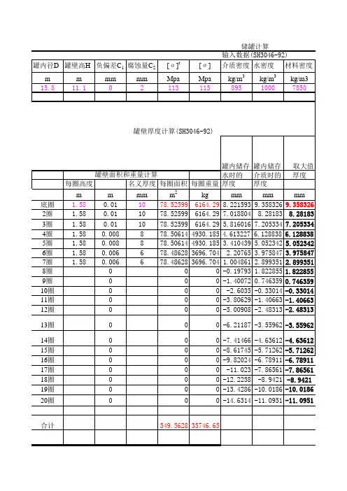
储罐设计计算注:此处的设计压⼒应为设计内压,不可等同于按液柱所确定的设计压⼒。
463.1cm 30.745KPa 0.540KPa1.001.001.38500.00罐壁筒体的临界压⼒:5.611KPat min =7.2mm H E =∑H ei=3.48mH ei ——罐壁各段当量⾼度,m ;H ei =H i (t min /t i )2.5罐壁各段当量⾼度如下:罐壁段号实际⾼度Hi (m )有效壁厚ti (mm )当量⾼度Hei(m )1223.20.112221.20.133219.20.174215.20.315213.20.446 1.59.20.8171.57.21.50罐壁设计外压: 2.2767KPa 0.60KPa如果:按6.4.9的规定选⽤。
P 0/3>[P Cr ]≥P 0/4应设置2个中间抗风圈于H E /3,2HE/3处。
6.1.2.中间抗风圈计算顶部抗风圈的实际截⾯模数 W=按图实际尺⼨计算(近似为T 型钢计算)∵ W>Wz故满⾜要求应设置3个中间抗风圈于HE/4,2HE/4,3HE/4处。
风载荷标准值P 0=2.25ωk +q=q---罐顶呼吸阀负压设定值的1.2倍∵[Pcr]>P0,故不需要设置中间抗风圈。
W z =0.083D 2H 1ωkP 0/2>[P Cr ]≥P 0/3ω0—基本风压值(<300时取300Pa)βz—⾼度Z处的风振系数,油罐取µs —风荷载体型系数,取驻点值µz —风压⾼度变化系数,ωk =βz µs µs ω0P 0>[P Cr ]≥P 0/2应设置1个中间抗风圈于H E /2处。
以此类推==5.2m in 48t E H D cr P8.771392MPa1罐底部垂直载荷 1.8009613MN A1=πDt 1.7492388m 2翘离影响系数取C L 1.4底部罐壁断⾯系数10.495433m 358.038423MN.m 9.921098MN.m 综合影响系数C z⼀般取0.4α=0.450.1404s R=D/212mKc 0.000432δ30.0192m αmax=0.45罐体影响系数Y 1⼀般取1.1m=m 1Fr5107701.9kg 罐内储液总质量8821592.2kg Fr 0.579其中:D/H1.846153828.98188MPa 199875MPa t------罐底圈壁板有效厚度0.0232mσ1<[σcr]合格0.472794m 0.026266Tg 0.35s储液晃动基本周期5.3643825sKs=1.095晃动周期系数(据D/H 按表D.3.3选取)m 1=0.25ρπD 2H动液系数(由D/H ,查D.3.4确定)6.2.2.罐壁许⽤临界应⼒[σcr ]=0.15Et/D储罐内半径储液耦连振动基本周期Q 0=10-6C z αY 1mg 地震影响系数(据Tc ,Tg ,αmax 按图D.3.1选取)地震影响系数(据Tw ,αmax 按图D.3.1选取)Tw=KsD 0.5α最⼤地震影响系数E-----设计温度下材料的弹性模量6.2.3.应⼒校核条件反应谱特征周期(按表D.3.1-1)耦连振动周期系数(据D/H 按表D.3.2选取)距底板1/3⾼度处罐壁有效厚度6.2.4.罐内液⾯晃动⾼度计算:罐内液⾯晃动⾼度h v =1.5αR竖向地震影响系数C v (7,8度地震区取1;9度地震区取1.45) N1=(m d +m t )gZ1=πD 2t/4总⽔平地震⼒在罐底部产⽣的地震弯矩M L =0.45Q 0H 罐壁横截⾯积(其中t 为底部罐壁有效厚度)总⽔平地震⼒在罐底部产⽣的⽔平剪⼒6.2.地震载荷计算:6.2.1.地震作⽤下罐壁底产⽣的最⼤轴向应⼒T c =K c H (R/δ3)0.5=产⽣地震作⽤⼒的等效储液质量M 56mm 地脚螺栓根径:d 150.67mm D b 24.256m n 48个σs235MPa1920647N16248039N 563479N 3416935N.m 15343260N迎风⾯积389.70m 2罐体总⾼16.24m 拱顶⾼度3.24m1130973N 2500.00Pa 7.2.3.储液在最⾼液位时,1.5倍计算破坏压⼒产⽣的升举⼒:2171239N16248039N 1800961N300981N A=2016.47mm 2单个地脚螺栓应⼒:σ=N b /A=149.26MPa每个地脚螺栓的承压⾯积:σ<2/3σs,合格7.4.地脚螺栓(锚栓)校核条件:N b =N/n d -W/n dN=Max[N 1,N 2,N 3,N 4]7.2.1.空罐时,1.5倍设计压⼒与设计风压产⽣的升举⼒之和:7.2.2.空罐时,1.25倍试验压⼒产⽣的升举⼒之和:设计风压产⽣的升举⼒N w =4M w /D b 设计风压产⽣的风弯矩M w =ω0A H H’N 2=PπD 2/4+Ne7.3地脚螺栓计算:N 3=P t πD 2/47.2罐体抗提升⼒计算:地脚螺栓圆直径:地脚螺栓个数:N 1=1.5PπD 2/4+N w 空罐时,设计压⼒与地震载荷产⽣的升举⼒之和地脚螺栓许⽤应⼒:地震载荷产⽣的升举⼒N e =Aσ7.3.2.单个地脚螺栓所承受的载荷:A H =H'D H'=H 1+H g Hg=Rs(1-COSθ)7.3.1.罐体总的锚固⼒为7.2.1,7.2.2.,7.2.3所计算升举⼒中的最⼤值W <N ,由于罐体⾃重不能抗倾覆⼒,故需要设置地脚螺栓W=(m t +m d )g罐体试验压⼒P t =1.25PN 4=1.5P Q πD 2/47. 地脚螺栓(锚栓)计算地脚螺栓直径:7.1地脚螺栓参数:罐体总重量。
缠绕大罐容器罐体力学性能校核计算书年月日合同编号:图纸编号:设备名称:制造单位:1.设计条件1.1工况参数:设计内压:______ Pa 设计外压:______ Pa 工作介质:______ 设计温度:______℃介质比重:______ 设计风压:______ Pa 抗震烈度:______ 积雪载荷:______ Pa 罐顶附加载荷:____ Pa 罐体附加载荷:____ Pa1.2几何参数:设备直径:______ mm 设备总高:______ mm设备容积:______ m32.设计依据标准规范主要参照ASME RTP-1-2007、HG/T 20696、HG/3983、JC/T587、Q/SH1020、SH3046、GB 50011(建筑抗震设计规范)等标准。
(上述未标注具体年份的,均参考依据最新版标准)3.计算过程(计算参数、抵抗外载荷稳定性、罐体刚度、罐体强度四个方面) 3.1 计算参数根据给定工况条件,按照ASME-RTP-1-2007标准计算方法,初步得出分段计算壁厚(见附件1),具体材料力学参数如下(见表1)。
3.2 载荷计算 3.2.1封头部分3.2.1.1设计内压力计算其中:K ——为超载系数,K=1.2 P max ——为罐内为设计压力q 1 ——为罐顶单位面积自重,pa1max q KPP -=内3.2.1.2设计外压力计算其中:q2——为罐内设计负压q3——为总附加载荷,顶部活载+雪载荷,pa3.2.2筒体部分3.2.2.1 设计内压力计算其中: H ——为罐内任意截面处贮液高度。
γ ——为贮液比重。
3.2.2.2 设计外压力计算 其中: K1——为体形系数。
K1=1.0K2——为风压转换系数,K2=2.25Kz ——为风压高度变化系数, Kz=1.0 W 0——为设计风压,paK3——为滞后系数,K3=1.2。
P ——为设计外压,常压容器取500pa 。
3.2.2.3 地震载荷计算(采用动液压力理论)其中: Cz ——为综合影响系数,取Cz=0.4;αmax ——为地震影响系数,取αmax =0.23W ——为产生地震载荷的贮罐总重量,取 321q q qP ++=外H KPγ+=max P 内P K W K K K z 3021P +=外WC Q z m ax 0α='W F W r =Fr ——为动液系数W'——为贮罐内贮液重量,N地震弯矩:其中: Hw ——为贮罐底面至贮液面的高度,m3.2.2.4风载荷计算 (取风载荷作用于贮罐重心位置)其中: A ——为风载荷作用面积,A=H ×DN ;C ——为形状系数,C=0.7风弯距:3.3 筒身应力计算 3.3.1 环向应力3.3.1.1 环向薄膜应力计算3.3.1.2底端部弯矩引起的环向应力其中: M ——为底部最大弯矩3.3.1.3组合环向应力拉应力: 其中:为有正压时,其他为零;2H M w0Q =AW CK Q z 0=[]拉压y y y y σσσσ≤+=21HQ M 21=()tDNP P y 21外内-=σ2111226tD MD y =σ1y σ压应力: 其中: 为有负压时,其他为零。
ATMOSPHERIC API 650 STORAGE TANKS常压API 650储罐FOREWORD序言This specification covers the minimum requirements for the design and fabrication of Field Erected Steel Storage Tanks used in the petroleum and petrochemical industries.This specification is intended to supplement API Standard 650, which is part of this specification. Paragraph numbers of this specification correspond to those in API 650. Paragraph numbers not found in API 650 are new paragraphs.该技术规范包括用于石油和石油化工业现场安装的钢制储罐设计和制造的最低要求。
该技术规范是对API 标准650的补充,是该技术规范的一部分。
该技术规范的段落数与API650的段落数相对应。
API 650中没有的段落为新增加的段落。
Paragraphs shall be highlighted as shown below to indicate the type of change from the API Standard:段落应加以标记(如下所示),以标明由API标准变化的情况:(Addition) New paragraph or supplemental requirements/clarifications to an existing paragraph.(新增)新增段落或对现有段落的补充要求/说明(Deleted) Paragraph deleted.(删减)段落已删除(Revision) A revision has been made as required.(修改)按要求已进行的修改。
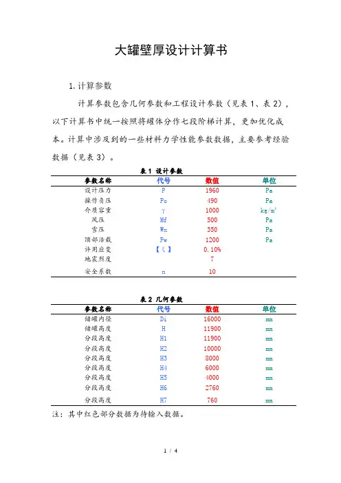
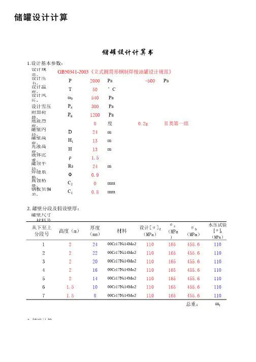
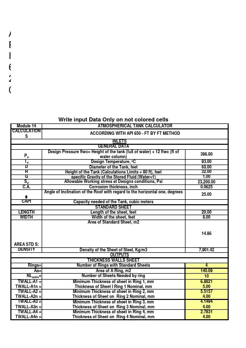
大罐壁厚设计计算书1.计算参数计算参数包含几何参数和工程设计参数(见表1、表2),以下计算书中统一按照将罐体分作七段阶梯计算,更加优化成本。
计算中涉及到的一些材料力学性能参数数据,主要参考经验数据(见表3)。
表1 设计参数参数名称代号数值单位设计压力P 1960 Pa操作负压Po 490 Pa介质容重γ1000 kg/m³风压Mf 500 Pa雪压Wx 350 Pa 顶部活载Pw 1200 Pa许用应变【ξ】0.10%地震烈度7安全系数n 10表2 几何参数参数名称代号数值单位储罐内径Di 16000 mm储罐高度H 11900 mm分段高度H1 11900 mm分段高度H2 10000 mm分段高度H3 8000 mm分段高度H4 6000 mm分段高度H5 4000 mm分段高度H6 2760 mm分段高度H7 760 mm注:其中红色部分数据为待输入数据。
2计算壁厚(基于ASME-RTP-1-2007) 2.1接触型Hoop Loading : Axial Loading :whereDi —— inside diameter, in. n ——design factor ,n=10.N ax —— axial force per circumferential inch of shell, lb/in. P 总 —— total internal pressure, psig (internal pressure plus hydrostatic head),P 总 = P+ρɡH i.Sa —— ultimate axial tensile strength, psi Sh —— ultimate hoop tensile strength, psi ta —— total wall thickness, in., for axial stressth —— total wall thickness, in., for circumferential tressnS D P t i /2h h 总=nS N t a/a ax=2.2缠绕型Hoop Loading : Axial Loading : whereE h —— hoop tensile modulus2.3薄壁模型(常压下)当K ≤1.2为薄壁容器 ;K >1.2则为厚壁容器。
按ASME标准设计储罐容积的计算方法
董海生
【期刊名称】《国外油气储运》
【年(卷),期】1995(013)002
【摘要】本文提出了计算具有准球形封头的ASME标准罐体积的简单方法。
此方法将准球形封头分为体积容易计算的三部分(球缺,截锥体和楔形圆环)。
最后给出了水平安置的带有准封头的圆筒形罐在部分充液情况下体积的计算方法。
【总页数】3页(P22-24)
【作者】董海生
【作者单位】无
【正文语种】中文
【中图分类】TE972.02
【相关文献】
1.锅炉散热损失简化计算方法与ASME PTC4标准中的计算方法比对分析 [J], 徐冉;张晓明;谭金锋;韩剑
2.用ASME和HEI标准设计除氧器 [J], 唐卉;陈悌德
3.按ASME标准设计和建造3000 m3饱和C4球罐 [J], 黄金国;徐亮;耿永丰;郭春光;李永泰;闫永超
4.标准设计预算工料统一计算方法 (煤矿标准设计预算专业会议文件之二) [J],
5.基于ASME标准设计的3000m3LPG球罐 [J], 冯义浩;占双林;董磊
因版权原因,仅展示原文概要,查看原文内容请购买。
ASME取证⽤储罐强度计算书汇总设计计算书Design Calculation Sheet1. 设计参数和条件Design Data and Condition:1) 设计所遵循的规范Applicable Design Code:ASME SectionⅧ,Div.1, 20132) 设计压⼒(p) : 内部1.3MpaDesign Pressure (p): Internal 1.3 MPa3) 设计温度: 60℃Design Temperature: 60℃4) 焊接接头系数(E): 壳体为0.85,封头为0.85(⽆缝)Joint Efficiency (E): 0.85 for Shell and 0.85 for Heads(seamless)5) 材料最⼤许⽤应⼒Material Max. Allowable Stress:Based on ASME Code Sec.Ⅱ, Part D Table 1A壳体和封头: SA516 Gr. 485,60℃时为138MPaShell & Heads: SA516 Gr. 485 Material Max. Allowable Stress is 138MPa at 60℃;接管: SA105M钢,60℃时为138MPaNozzles:SA105M Steel Material Max. Allowable Stress 138 MPa at 60℃;6) 媒介: 空⽓Medium: Air (Non lethal)7) 封头类型: 2:1椭圆封头Head type: 2:1Ellipsoidal Head;8) 其他载荷: 依据“客户设计说明书”(Doc. No. TS-15-01 Rev.0)Others Loadings: As Shown in“Customer’s Design Specification”(Doc. No. TS-15-01 Rev. 0)9) 腐蚀余度:2.0 mmCorrosion Allowance: 2.0 mm10) 容器外形和尺⼨:依据“客户设计说明书”(Doc. No. TS-15-01 Rev.0)Layout of Vessel and Dimension:As Shown in“Customer’s Design Specification”(Doc. No. TS-15-01 Rev. 0) 11) 钢印要求: 要求ASME标识Stamp required: ASME Certification Mark required12) NB要求: 不要求NB钢印NB stamp required: NO “NB” stamp required.Verify for UG-22 LoadingPressure符号 Symbols:t= 壳体要求最⼩厚度,mmt = minimum required thickness of shell, mm P = 内部设计压⼒, 1.3MPaP = internal design pressure, 1.3 MPa [see UG-21] R = 预计容器筒内半径, 250mmR = inside radius of the shell course under consideration, 250mm S = 最⼤许⽤应⼒值,138MPa S = maximum allowable stress value, 138MPa [ see ASME Code Part II DTable 1A for material SA-516 Gr.485] E = 焊接接头系数,0.85E = joint efficiency, 0.85 [see Table UW-12(1)]Since P=1.3MPa is less than 0.385SE=45.16MPa, Formula UG-27(c)(1) is used:)(2.811.36.085.0381)2025(3.16.0mm P SE PR t =?-?+?=-=考虑腐蚀裕量:Consider of corrosion allowable: tr= t + Ca = 2.81 + 2.0 = 4.81mmThese formulas will govern only when the circumferential joint efficiency is less than one-half the longitudinal joint efficiency, according to UG-27(c) (2) note 20, the formula UG-27(c) (2) for longitudinal stress needn’t considered. 公称钢板规则厚度=10mmNominal Plate Thickness Ordered = 10 mm钢板厚度可允许下偏差=0.25mm[see UG-16(c)] Plate Under tolerance=0.25 mm [ see UG-16(c)]UG-16 (b)(4) the minimum thickness of pressure retaining components >2.5mm for air service(exclusive any corrosion allowance). 实际使⽤厚度=10-0.25=9.75> 4.81mm ,并且也>2.5+2mm,可以。
储罐的容积计算公式储罐在我们的生活和工业生产中可太常见啦!从储存石油的大型储罐,到储存水的小型储罐,它们都有着各自的作用。
那要算出储罐的容积,这里面可有不少学问呢。
先来说说常见的储罐形状,有圆柱体的、长方体的,还有一些不规则形状的。
咱们先从最简单的圆柱体储罐说起。
圆柱体储罐的容积计算公式是:V = πr²h 。
这里的 V 代表容积,π呢,就是那个约等于 3.14 的圆周率,r 是圆柱体底面的半径,h 则是圆柱体的高度。
比如说,有一个圆柱体储罐,底面半径是 2 米,高度是 5 米。
那它的容积就是 3.14×2²×5 = 62.8 立方米。
我之前在一家工厂实习的时候,就碰到过计算储罐容积的事儿。
那是一个存放化工原料的储罐,老板让我们几个实习生去算一算它能装多少原料。
我们拿着尺子,小心翼翼地测量着储罐的半径和高度。
我记得当时阳光特别大,晒得我们满头大汗,但是大家都特别认真,因为这可关系到工厂的生产计划呢。
长方体储罐的容积计算公式是:V = lwh 。
这里的 l 是长度,w 是宽度,h 是高度。
假设一个长方体储罐,长 3 米,宽 2 米,高 4 米,那它的容积就是3×2×4 = 24 立方米。
不规则形状的储罐计算起来就稍微复杂一些,可能需要用到积分或者其他更高级的数学方法。
但在实际生活中,我们常常会把不规则的储罐近似地看作规则形状来计算,这样能大大简化计算过程,也能满足我们的基本需求。
总之,不管储罐是什么形状,只要掌握了相应的计算公式,再加上准确的测量,就能算出它的容积啦。
回到开头说的,储罐虽然看似简单,但其容积的计算却在很多领域都有着重要的作用。
比如在石油化工行业,准确计算储罐的容积能帮助企业合理安排生产和储存;在城市供水系统中,知道储罐的容积可以保障居民用水的稳定供应。
所以啊,别小看这储罐的容积计算公式,它可是有着大用处的呢!。
常压罐车容积计算公式
在物流运输中,常压罐车是一种常见的运输工具,用于运输各种液体或散装物品。
为了确保运输的安全和效率,对常压罐车的容积进行准确的计算是非常重要的。
常压罐车的容积计算公式如下:
容积 = 长度× 宽度× 高度
在计算容积时,我们需要准确测量罐车的长度、宽度和高度。
首先,我们测量罐车的长度,这是指罐车的前后方向的距离。
然后,我们测量罐车的宽度,这是指罐车的左右方向的距离。
最后,我们测量罐车的高度,这是指罐车的上下方向的距离。
在测量过程中,我们需要注意一些细节。
首先,我们需要确保测量的起点和终点都与罐车的边缘对齐,以确保测量的准确性。
其次,我们需要使用适当的测量工具,如尺子或测量仪器,来获得准确的测量结果。
最后,我们需要重复测量几次,以确保结果的准确性。
在计算容积时,我们需要将测量结果转换为相应的单位。
常用的容积单位包括立方米、升和立方英尺。
根据具体情况,我们选择合适的单位进行计算。
通过准确计算罐车的容积,我们可以更好地安排货物的装载和运输。
这不仅可以提高运输的效率,还可以减少运输成本。
同时,准确计
算罐车的容积也可以帮助我们更好地规划运输路线,确保货物的安全和稳定运输。
常压罐车容积的计算对于物流运输非常重要。
通过遵循上述公式和测量方法,我们可以准确计算罐车的容积,并为货物的装载和运输提供有效的指导和支持。
这将有助于提高运输效率和安全性,为物流行业的发展做出贡献。
罐体描述:单V形结构,小封头尺寸Ø1810mm,V形最大截面高度30mm,宽度2500mm,大封头直径Ø2060mm,筒体直线段(不含两端封头)长度8230mm;运输介质:粉煤灰;比重:1.0吨/立方米;罐体的容积计算:1、罐体额定容积=载质量(吨)/密度(吨/立方米)(立方米)2、罐体有效容积=罐体总容量=罐体额定容积x1.05=30.3x1.05=31.8(立方米)3、封头容积:封头为碟形封头,前封头底部面积同罐体前端截面积为2.51,后封头底部面积同罐体后端截面积为3.25,前封头蝶形封头高为370mm,后封头蝶形封头高为420mm,根据“JB/T4746-2002钢制压力容器用封头”标准附录E---表E.1DHB蝶形封头内表面积、容积查询表中的参数,则封头体积V封头=V1+V5≈0.64+1.0=1.64(立方米)4、利用CAXA程序自带的工具软件可以直接查询出各截面的面积,即:截面1:S1=2.51m;截面2:S2=4.26m;截面3:S3=5.80m;截面4:S4=S2=4.26m;截面5:S5=3.25m;罐体按外形尺寸计算容积:V罐体=V1+V2+V3+V4+V5=V封头+V2+V3+V4222=1.64+(S1+S2)/2xH1+(S2+S3)/2xH2+(S3+S4)/2xH3+(S4+S5)/2xH4=1.64+(2.51+4.26)/2X1.379+(S4.26+5.80)/2X2.655+(5.80+4.26)/2X3.319+(4.26+3.25)/2X0.876=39.65m3罐体计算容积x0.8= V总X0.8=39.65X0.8=31.72m³(立方米)<罐体有效容积=31.8(立方米)罐体外形尺寸和各截面位置:S1=2.51 m2S2= S4=4.26 m2S3=5.80 m2S5=3.25 m2。
储罐工艺指标参数制定规范一、常压储罐工艺指标参数(一)液位1、基本要求1)常压储罐操作液位上限应小于设计储存液位;固定顶罐操作液位下限不得低于进油线顶部610mm,浮顶罐和内浮顶罐操作液位下限应高于浮船支撑高度200mm以上。
2)操作液位应在高报和低报液位之间。
2、储罐液位计算方法1)固定顶罐设计储存液位(高液位报警)按下式(1)计算:h设=H1-(h1+ h2+ h3) (1)式中:h设——固定顶罐设计储存液位,mH1——罐壁高度,mh1——泡沫管开孔下缘至罐顶端的高度,mh2——10min~15min储罐最大进液量的折算高度,mh3——安全裕量,可取0.3m(包括泡沫混合厚度和液体的膨胀高度),m 2)固定顶罐高高液位报警设定按下式(2)计算:h高= h设+ h2 (2)式中:h设——固定顶罐设计储存液位,mh2——10min~15min储罐最大进液量的折算高度,m3)浮顶罐(内、外)设计储存液位(高液位报警)按下式(3)计算:h浮=h4-( h2+ h3) ······(3)式中:h浮——浮顶罐的设计储存液位,mh4——浮盘设计最大高度(浮盘底面),mh3——安全裕量,可取0.3m(包括液体的膨胀高度保护浮盘所需余量),m 4)浮顶罐(内、外)高高液位报警设定按下式(4)计算:h高=h浮+h2 (4)式中:h高——高高液位报警设置高度,m5)相关参数:(1)浮顶罐(即外浮顶罐)浮盘设计最大高度(浮盘底面)参考值:罐壁顶以下1.5~1.6m。
(2)内浮顶罐:钢制浮盘,罐壁顶以下0.9~1.0m;铝制浮盘,罐壁顶以下0.5~0.6m。
3、高低液位报警设置规范常压储罐高低液位报警设定取值表储罐类型液位取值浮顶罐(内、外)低低液位报警浮船支撑高度+200mm处取值;或低液位报警高度减去10min-15min储罐最大收油量的折算高度。
低限液位报警浮船支撑高度+400mm处取值;或低低液位报警高度加上10min-15min储罐最大输出量高度。