捷迅易联无线数传电台YL-900ID规格书
- 格式:pdf
- 大小:926.12 KB
- 文档页数:15
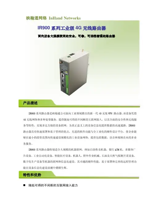
映翰通网络InHand NetworksIR900系列工业级4G无线路由器面向设备大规模联网的安全,可靠,可远程管理的路由器产品描述IR900系列路由器是映翰通公司面向工业领域推出的新一代4G无线VPN 路由器。
该设备凭借4G无线网络和多种宽带服务,提供随处可得的不间断的互联网接入,以其全面的安全性和无线服务等特性,实现多达万级的设备联网,为真正意义上的设备信息化提供数据的高速通路。
IR900路由器具有快速部署和易于管理的优点,先进的软件功能与全工业化的硬件设计平台,使企业能够在最小的投资范围内快速建设规模化的工业设备网络,提供包括数据,语音和视频在内的多业务服务。
IR900系列路由器特别适合大规模的机器联网,例如自助售卖机器,银行ATM机,多媒体广告设备,工业自动化设备,智能医疗设备,机器人,野外作业机械,石油及天然气探测开采设备,数字化生产设备等机器的联网和信息化建设,其卓越的硬件性能,易于部署和完善的远程管理功能在设备信息化建设浪潮中熠熠生辉。
特性和优势随处可得的不间断的互联网接入能力冗余广域网链路:快速以太网,3G/4G,多种DSL,实现业务的连续性和广域网的多样性。
无论设备处于商业区,还是在人迹罕见的野外,企业均可从容选择宽带服务或者覆盖广泛的3G/4G网络,以保证设备互联互通。
同时,当主宽带链路故障时,可使用3G/4G备份网络,以保持设备处于不间断的网络通信中,大大提高了业务的可靠性。
⏹支持大规模部署在机器联网的应用中,企业面临的是上千台甚至上万台机器的联网,要部署以万计数的VPN 路由器,对于企业的网络管理人员,是一个巨大的挑战,IR900针对这样的现实需求,提供以下功能,使快速的大规模部署成为现实:●提供WEB和CLI多种配置方式,方便企业网络管理人员快速配置数以千计的路由器。
●高效的远程集中网管:对于大规模的设备联网项目,由于数量多,设备分散广泛,设备操作人员缺乏网络技能,VPN路由器的远程网管功能尤为重要。

Experts in Wired & Wireless SolutionsAsk the L-com Expert - Ph. 800-343-1455 - Fx . 978-689-9484Ask the L-com Expert - Ph. 800-343-1455 - Fx . 978-689-948445 Beechwood DriveNorth Andover, MA 01845-1092L-com’s audio and video products include thousands of popular audio and video cables, connectors and adapters with the ability to adapt components and products for customer-specific cable designs. Audio and video cable interfaces include: HDMI, mini HDMI, VGA, SVGA, DVI, DisplayPort, mini-DIN, 3.5mm audio, 75-ohm coax, and RCA. Fast turnaround on custom and low-volume configurations.easy access and saving space• L-com exclusive: Color-coded cable assemblies indicate pin locations for each color wire• IP67 shielded waterproof cable assemblies• SVGA cables provide 360º shielding for superior video performance • Super Thin SVGA series saves 2 inches over standard SVGA for tight fitting spacesassemblies featuring 50 ohm, 75 ohm and 78 ohm. Ideal for GPS applications, video systems, telecommu-nication systems and infrastructure, WISP applications and WAN/LAN networks. Fast turn around requests for custom and low-volume coaxial cable confgurations.• Largest offering of angular/space-saving products• Wide variety of coaxial connector types: UHF , Mini-UHF , SMB, BNC, MCX, SMC, TNC, N, SMA, QMA• Standard and reverse polarity connectors and assemblies• Cable types include: Standard and Hi-Temp RG-Series, Plenum rated, Digital Grade, Standard and Ultra-Flex Low Loss• High performance Semi-Rigid and Formable cable assembliesWith 12 different antenna configurations available, L-com’s HyperLink antennas perform across a wide range of frequencies and offer a variety of gain specifications and beamwidth coverage to meet the requirements for most indoor and outdoor wireless system applications.• Operating frequency range from 400 MHz to 5.8 GHz• Largest selection of antenna types which includes omnidirectional, yagi, patch, panel, grid, dish, rubber duck, sectorial, ceiling and mobile • Wide range of applications supported including IEEE 802.11a/b/g/n wireless LAN systems, WiFi, WiMAX and 900 MHz ISM• Superior HyperLink antenna design outperforms other antennas especially in harsh environments• Quick turnaround on custom antenna orderscable assemblies, legacy applications served include PC to PC and peripherals; PC drives; laptop & desktop connections to external storage (such as hard & optical drives); external high speed connectivity to external storage devices; DVD-ROM, CD-ROM tape and floppy drives; analog audio; mouse connections; MIDI applications; S-Video and PS/2 keyboard and mouse interconnects.numbers than the competition• FireWire (IEEE 1394) solutions for Apple/Sony Legacy (“I-Link”)• Largest DIN & Mini-DIN selection of exclusive user-friendly products • Standard EMI SCSI solution• Standard SCSI assemblies for 1, 2, 3, & 5 Interfaces• SATA assemblies support data transfer rates as high as 3.0 Gb/sExtensive product offering features popular data cable, null modem cables, D-Sub connectors, high-density cables and more. Hard-to-find items including double shielded, panel-mount and low smoke zero halogen (LSZH) jacketed cables are available in stock. Custom and low-volume D-Sub cable configurations requests are welcome.• CS2 series has double-shielded cable (braid+ foil) for additional EMI protection• All steel box construction provides 360º shielding and superior strain relief• High density Gender Changers available• DB9, DB15, DB25, HD15 connector adapters for field termination, D-sub covers, D-sub design kits• IP67 shielded waterproof cable assembliesL-com fiber optic cable assemblies are 100% factory-tested and carry a one year manufacturer’s warranty. L-com offers a complete line of accessories and the most popular types of Simplex, Duplex, Breakout and Distribution cable for the telecom/datacom, CATV , test equipment, LANS, Gigabit Ethernet, video, multimedia, medical, military and ATM markets.low toxicity and low corrosion• MT-RJ connectors are for emerging small form factor assemblies • IP67 shielded waterproof cable assemblies • Utilizes PC; UPC; or APC polish• ST assemblies feature rust resistant stainless steel bodies • 10 Gig multimode fiberL-com’s HyperLink indoor/outdoor bi-directional amplifiers are available for export, military, licensed amateur radio and OEM component sales as part of complete FCC Certified Systems. (Individual amplifier products are not offered for sale in the USA)• Amplifiers support frequencies of 900 MHz - 5.8 HGz • Transmit power from 100 mW to 25 Watts• In 2002, HyperLink (now L-com) was the first company to offer802.11g bi-directional amplifiers with Automatic Power Control (APC). APC holds transmit power constant regardless of cable length • FCC Certified amplifier kits require no pre-qualification in USproducts complement and support the extensive cabling and connector product oering.L-com manufactures one of the most comprehensive lines of NEMA-rated weatherproof industrial enclosures.Available in a wide range of sizes and power options aswell as with integral heating and/or cooling.• Full line of fiber optic, coaxial, RJ45, Cat45, Cat 5, Cat5e, Cat6, and data & serial connection interfaces in 1U (1.75 ”) and 2U (3.5”) options• Universal Rack System allows for quick and inexpensiv e • NEMA enclosures available for 120VAC, 240VAC, 12VDC and PoE operation• Universal 120-240VAC enclosures for worldwide applications • ULlisted enclosures availableEach L-com USB cable is functionally tested to provide the highest performance at competitive prices. L-com offers an extensive array of USB 2.0 and USB 3.0products for communications, entertainment, medical, military and automotive applications. Fast turn around on requests for custom and low-volume USB cable configurations.combination options and fit any panel thickenss • IP67 shielded waterproof cable assemblies• Several options available to panel mount USB connectors on enclosures • USB connectors, connector hoods and connector covers • Right angle beige USB connectors; coilcord with Mini USB• Off-the-shelf cable assembly and bulk cable options with power conductors ranging from 20 to 28 AWGof premise wiring cable assemblies, connectors, and accessories required for LAN, phone equipment and commercial building structured cabling systems. Prod-uct offering includes Cat 5, Cat 5E, Cat 6 and Ethernet crossover cable assemblies, backbone T elco cable assemblies, splitters, couplers, adaptors jacks, wall plates, panels, gender changers bulk cable and other Ethernet & fieldbus network accessories.• L-com exclusive: Superior right angle Cat 5E cable assembly design (patent Pending)• Tool-less jack series offers superior performance with a unique offset IDC connection that maintains conductor pairs up until the termination point and speeds installation• IP67 shielded waterproof cable assemblies• Extensive offering of telecom/modular accessories • Flat silver satin modular cable availableL-com’s Power-over-Ethernet (PoE) midspans and Ethernet switch products provide high perfor-mance, cost effective solutions for providing data and power on a single Cat 5 cable to remote de-vices such as wireless access points, access serv-ers, outdoor routers, IP phones, security cameras, security scanning systems and other devices.and PoE hub products• Full line of Ethernet connectors and cable assemblies available• PoE solutions significantly decrease traditional electrical installation costs• PoE injectors with integral surge protectionAsk the L-com Expert - Ph. 800-343-1455 - Fx . 978-689-9484Ask the L-com Expert - Ph. 800-343-1455 - Fx . 978-689-9484lightning and surge protectors in-stock and ready for purchase. From coaxial protectors for protection of wireless equipment such as access points to Ethernet data line protectors designed to protect 10/100/1000 Base-T networking equipment such as servers, PoE equipment and IP cameras.• CAT 5/5e/6 Ethernet data line protectors • 4-20 mA current loop protectors • RS-422/485/232 protectors • Telephone/DSL/T1 protectors • Audio and video protectors • USB protectors。
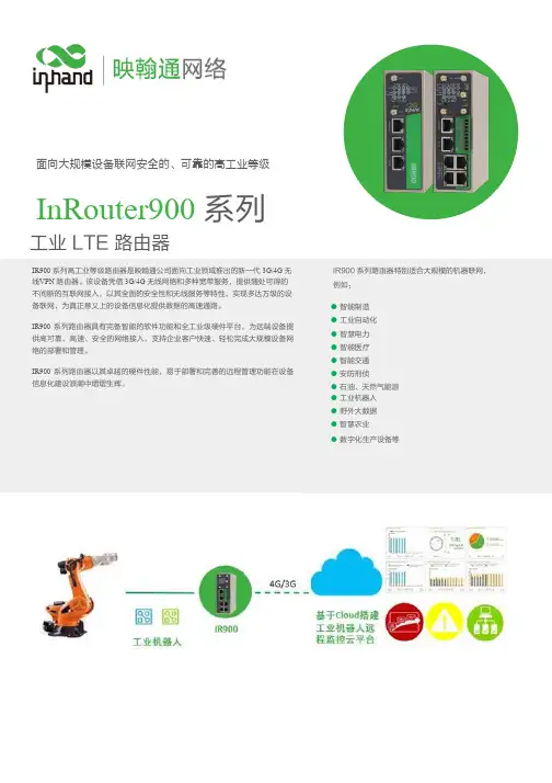
面向大规模设备联网安全的、可靠的高工业等级InRouter900 系列工业 LTE 路由器应用方案IR900 系列高工业等级路由器是映翰通公司面向工业领域推出的新一代 3G/4G 无线VPN 路由器。
该设备凭借 3G/4G 无线网络和多种宽带服务,提供随处可得的不间断的互联网接入,以其全面的安全性和无线服务等特性,实现多达万级的设备联网,为真正意义上的设备信息化提供数据的高速通路。
IR900 系列路由器具有完备智能的软件功能和全工业级硬件平台,为远端设备提供高可靠、高速、安全的网络接入,支持企业客户快速、轻松完成大规模设备网络的部署和管理。
IR900 系列路由器以其卓越的硬件性能,易于部署和完善的远程管理功能在设备信息化建设浪潮中熠熠生辉。
IR900 系列路由器特别适合大规模的机器联网, 例如:● 智能制造 ● 工业自动化 ● 智慧电力 ● 智能医疗 ● 智能交通 ● 安防刑侦 ● 石油、天然气能源 ● 工业机器人 ● 野外大数据 ● 智慧农业● 数字化生产设备等特性和优势InRouter900 规格书+ 支持4G LTE+ 支持高效完成大规模设备网络部署 + 冗余设计,双SIM 卡,双链路备份,保障 设备网络通信不间断 + 多种动态路由协议 + 支持多端口,可划分VLAN + 支持WLAN + 支持GPS+ 支持 SNMP 及映翰通 Device Manager 云平台,实现高效的远程集中网管 + 用户体验计划,优化服务协助管理 + 全工业化设计,无惧恶劣条件的挑战产品尺寸 (mm)针脚 定义 说明1 RXD 串口 RS232 接收 2 TXD 串口 RS232 发送3 GND 串口 RS232 信号地4 A 串 口 RS485 + 5 B 串口 RS485-6 IN 数字量输入信号7 COM 数字量输入接地 8NC 数字量输出信号 9COM数字量输出接地产品规格InRouter900 规格书CE 、FCC 、UL 、PTCRB 、CCC 、V erizon 、A T&T 、E-MARK 、IC 、IMDA 、RCM订购信息InRouter900 规格书型号编号: IR91X-<WMNN>-<W>-S-<GPS><N1>:模块<WMNN>:无线通讯类型 & 模块<W/空>:WLAN (仅IR915)S:串口类型(仅IR915)<G/空>:GPS(仅 IR915)型号IR912L-TL01IR915L-TL01-<W>-S-<GPS>L:含 4G LTE 模块(For China, LTE CAT4)LTE-FDD Band 1/3/5/8LTE-TDD Band 34/38/39/40/41TD-SCDMA Band 34/39WCDMA Band 1/8GSM 900/1800MHzW: Wi-Fi<空>: 无 Wi-FS: RS232RS485G: GPS<空>: 无 GPSIR912L-FQ58IR915L-FQ58-<W>-S-<GPS> L:含 4G LTE 模块(For Europe, Asia & Pacific area, China, ,LTE CAT4 )LTE-FDD Band 1/3/7/8/20/28LTE-TDD Band 38/40/41WCDMA Band 1/2/5/8GSM 850/900/1800/1900MHzW: Wi-Fi<空>: 无 Wi-FS: RS232RS485G: GPS<空>: 无 GPSIR912L-FS18IR915L-FS18-<W>-S-<GPS> L:含 4G LTE 模块(For North America, AT&T,LTE CAT3)LTE-FDD Band 2/4/5/17UMTS(HSPA+) Band 2/4/5EDGE/GPRS/GSM 850/900/1800/1900MHzW: Wi-Fi<空>: 无 Wi-FS: RS232RS485G: GPS<空>: 无 GPSIR912L-FQ39IR915L-FQ39-<W>-S-<GPS> L:含 4G LTE 模块(For North America, T-Mobile, Verizon, AT&T, LTE CAT6)LTE-FDD Band 2/4/5/7/12/13/25/26/29/30/66WCDMA Band 2/4/5W: Wi-Fi<空>: 无 Wi-FS: RS232RS485G: GPS<空>: 无 GPSIR912L-FQ78IR915L-FQ78-<W>-S-<GPS> L:含 4G LTE 模块(For Australia & South America, LTE CAT4)LTE-FDD Band 1/2/3/4/5/7/8/28LTE-TDD Band 40WCDMA Band 1/2/5/8 GSM Band 2/3/5/8W: Wi-Fi<空>: 无 Wi-FS: RS232RS485G: GPS<空>: 无 GPSIR912P-EN00IR915P-EN00-<W>-S-<GPS> 无 3G/4G 模块无 3G/4G 模块W: Wi-Fi<空>: 无 Wi-FS: RS232RS485G: GPS<空>: 无 GPS例子: IR915L-TL00-W-S-G 5口工业无线路由器,支持FDD网络、GPS定位、WLAN、RS232&RS485、I/O接口注:设备初次登录会提示是否加入用户体验计划,同意后默认接入映翰通云平台,用户可在设备服务>用户体验计划菜单中修改。
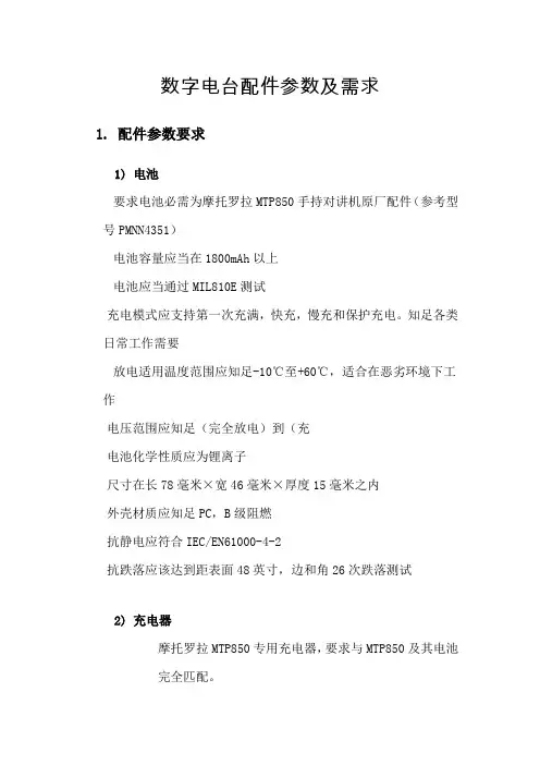
数字电台配件参数及需求
1. 配件参数要求
1)电池
要求电池必需为摩托罗拉MTP850手持对讲机原厂配件(参考型号PMNN4351)
电池容量应当在1800mAh以上
电池应当通过MIL810E测试
充电模式应支持第一次充满,快充,慢充和保护充电。
知足各类日常工作需要
放电适用温度范围应知足-10℃至+60℃,适合在恶劣环境下工作
电压范围应知足(完全放电)到(充
电池化学性质应为锂离子
尺寸在长78毫米×宽46毫米×厚度15毫米之内
外壳材质应知足PC,B级阻燃
抗静电应符合IEC/EN61000-4-2
抗跌落应该达到距表面48英寸,边和角26次跌落测试
2)充电器
摩托罗拉MTP850专用充电器,要求与MTP850及其电池
完全匹配。

第九章数字无线对讲系统第一节说明数字无线对讲系统(以下简称数字无线对讲)是一个以放射式的室内/室外布线系统,可为业主人员供应平时和应急通服气务,此中,用户终端(即手持台和车载台等)能在无线对讲系统覆盖地区内的非固定地点进行通讯。
本系统需要采纳数字中继台与数字手持机相联合的无线对讲系统,系统中全部设施和器件须工作在400MHz频段范围。
第二节系统构成此系统起码应包含下述设施和组件。
数目和设施选型应依据覆盖地区而定。
数字中继台及发射合路器、接收分路器、带通双工器对讲机(以下简称手持台)无线对讲管理工作站(遥距控制组件)干线放大器或射频干线放大器射频同轴电缆线、定向耦合器、功分器室内/室外天线机柜蓄电池第三节系统功能设计要求承包单位须为本项目供应设计、供应、安装、调试、开通等工作,须为业主方交托出正常、完美并能立刻投入使用的无线对讲系统。
产品技术标准系统制式须切合所属地无线电委员会或有关部门所认同的TDMA技术标准。
本系统须向当地无线电委员会报验并经过。
需切合法例本系统需切合工信部公布[2009]666号文件《对于150MHz400MHz频段专用对讲机频次规划和使用管理有关事宜的通知》。
信道及扩容依据需要,本项目计划安装鉴于1个数字中继台的数字无线对讲系统,此系统一定能提供1个无线电频道(即频次),2个业务信道(2个业务信道由2个时隙承载)。
系统应拥有扩容功能,如增添中继台频道和增添手持台数目。
手持台招标数目本次招标暂计划配置20部手持台(标配中需要含1个锂电池和1个充电座)。
通话分组计划每个部门划归为1个通话组,将有4个部门,分红4个通话组。
要求通话组内实现通话群呼;通话组间,能够实现通话内容互相隔绝。
通话分组做以下计划:信道部门名称信道分派信道属性1物业工程部1信道1时隙在线,覆盖全地区,共享此信道可经过旋2保洁部1信道1时隙在线,覆盖全地区,共享此信道转信道拨钮,实现3其余部门1信道1时隙在线,覆盖全地区,共享此信道跨部门通信,也可4保安部1信道2时隙在线,覆盖全地区,独占此信道锁定在某个信道直通讯道其余暂时部门直通频次非中继频次,小范围通话或中继上。
Wireless Radio ModemUser’s ManualWarrantyAll products manufactured by ICP DAS are warranted against defective materials for a period of one year from the date of delivery to the original purchaser.WarningICP DAS assume no liability for damages consequent to the use of this product. ICP DAS reserves the right to change this manual at any time without notice. The information furnished by ICP DAS is believed to be accurate and reliable. However, no re-sponsibility is assumed by ICP DAS for its use, nor for any in-fringements of patents or other rights of third parties resulting from its use.CopyrightCopyright 1999 by ICP DAS. All rights are reserved. TrademarkThe names used for identification only maybe registered trademarks of their respective companies.Date:2001-11Table of Contents1. Introduction (4)1.1 Block Diagram (4)1.2 Specifications (5)1.2.1 SST-900EXT Wireless Radio Modem (5)1.2.2 SST-2400EXT Wireless Radio Modem (6)1.2.3 SST-900A External 900MHz Antenna (7)1.2.4 SST-2400A-3 External 2.4GHz Antenna (7)1.2.5 SST-2400A-12 External 2.4GHz Antenna (8)1.2.6 SST-2400A-13 External 2.4GHz Antenna (8)1.3 Pin Assignment (9)1.4 Jumper Setting (10)1.5 Wire Connection (11)1.6 Dimension (14)1.6.1 SST-900EXT and SST-2400EXT (14)1.6.2 DIN-RAIL Mounting (15)1.6.4 Pannel Mounting (16)2 Configuration (17)2.1 Full-duplex and Half-duplex (17)2.2 Synchronous and Asynchronous (18)2.3 Configuration Select (19)2.4 Operation Mode 1 (20)2.5 Operation Mode 2 (21)2.6 Operation Mode 3 (22)3 Application (23)3.1 Peer-to-Peer Communication (23)3.2 Asynchronous Connection (24)3.3 Multiple PCs Communication (25)3.4 Connect I-7000 Modules (26)3.5 Communication Bridge (27)3.6 Network Communication (28)1. IntroductionThe SST-900 and SST-2400 are radio modems that can be used in multiple access networking. The transmission method includes peer-to-peer, multi-point structure for wireless data communication. Based on direct sequence spread spectrum and RF technology operating in ISM bands, 902-928Mhz for SST-900 and 2426-2458MHz for SST-2400.1.1 Block Diagram1.2 Specifications1.2.1 SST-900EXT Wireless Radio ModemRF Communication TransceiverFrequency Band :909 to 924 MHz for SST-900Channel Spacing : 2.048 MHz (8 channels jumper select) Output Power : 20±2 dBmModulation : GMSKTime Division DuplexingTransimition Range : Max 300MSST TransceiverDirect Sequency Spread SpectrumNon-Overlapping Channels : 8 channels, jumper select (only for full-duplex operation)Full-duplex or Half-duplex, jumper selectSynchronization or Asynchronization, jumper selectSerial Communication InterfaceRS-232(TxD, RxD, GND) and RS-485(D+, D-), jumper selectBaudrate : 600bps to 57600bps, jumper selectEnvironmentOperating Temperature : 0°C to 50°CStorage Temperature : -30°C to 70°CPower SupplyInput : +10 to +30VDC, unregulatedConsumption : 1.5W1.2.2 SST-2400EXT Wireless Radio Modem RF Communication TransceiverFrequency Band : 2426 to 2458 MHzChannel Spacing : 2.048 MHz (8 channels jumper select) Output Power : 20±2 dBmModulation : GMSKTime Division DuplexingTransimition Range : Max 300M with bundled antennaMax 1000M with SST-2400A-3 antennaMax 5000M with SST-2400A-12 antennaMax 5000M with SST-2400A-13 antenna SST TransceiverDirect Sequency Spread SpectrumNon-Overlapping Channels : 8 channels, jumper select (only for full-duplex operation)Full-duplex or Half-duplex, jumper selectSynchronization or Asynchronization, jumper selectSerial Communication InterfaceRS-232(TxD, RxD, GND) and RS-485(D+, D-), jumper select Baudrate : 600bps to 57600bps, jumper selectEnvironmentOperating Temperature : 0°C to 50°CStorage Temperature : -30°C to 70°CPower SupplyInput : +10 to +30VDC, unregulatedConsumption : 1.5W1.2.3 SST-900A External 900MHz Antenna External antenna for SST-900EXTMaximum Distance : 1000MWeight : 1000gAntenna Gain : 5dBCable : RG58C/U, 4M1.2.4 SST-2400A-3 External 2.4GHz Antenna External antenna for SST-2400Maximum Distance : 1000MWeight : 150gAntenna Gain : 3dBCable : RG58A/U, 1M1.2.5 SST-2400A-12 External 2.4GHz Antenna External antenna for SST-2400Maximum Distance : 5000MWeight : 850gAntenna Gain : 12dBCable : RG58A/U, 1M1.2.6 SST-2400A-13 External 2.4GHz Antenna External antenna for SST-2400Maximum Distance : 5000MWeight : gAntenna Gain : ??dBCable : RG58A/U, 1M1.3 Pin AssignmentDSR Reserved signal of diagnosticRX Receive of RS-232TX Transimit of RS-232GND Ground of RS-232(Y)D+Data+ of RS-485(G)D-Data- of RS-485(R)+Vs+10 to +30V DC power supply input (B)GND Ground of power supply input1.4 Jumper SettingFactory default jumper setting :(1) Channel 3(2) Frequency 915.968/2439.936MHz (3) Baudrate 9600bps(4) Full-duplex(5) Slave(6) Synchronous(7) Interface RS-2321.5 Wire ConnectionWire Connection for PC’s RS-232 and SST-900/2400 : 1.The jumper(7) position inRS-232 side2.Connect SST-900/2400’sGND to CA-0910’s GND,TX to TX and RX to RX.3.Connect CA-0910’s DB-9female connector to PC’sR S-232D B-9m a l econnector.Wire Connection for I-7000 and SST-900/2400 via RS-485 1.The jumper(7) position inRS-485 side.2.D+ of SST-900/2400 to D+of RS-485 bus.3.D- of SST-900/2400 to D-of RS-485 bus.Connect SST-900EXT with SST-900AConnect SST-2400EXT with SST-2400A-3Connect SST-2400EXT with SST-2400A-12Connect SST-2400EXT with SST-2400A-13Rear View Front View Side ViewBottom ViewTop View1.6 Dimension1.6.1 SST-900EXT and SST-2400EXT1.6.2 DIN-RAIL MountingAntenna ofSST-2400EXT Antenna of SST-900EXT1.6.4 Pannel Mounting2 Configuration2.1 Full-duplex and Half-duplexFull-duplex is to transimit and receive data at the same time, and half-duplex is to transimit and receive data at seperate time. While using full-duplex mode, only peer-to-peer operation is available. For work in multi-point operation, half-duplex is the only choice.While working in full-duplex mode, one of the two com-munication modules is set as master and the other is set as slave. And both modules have same baudrate, frequency and channel select.While working in half-duplex mode, the all modules have the same configuration. The baudrate and frequency select need all the same, and all modules select slave mode. The channel se-lect is invalid for half-duplex mode. In half-duplex mode, only one module may transimit at the same time. If more than one mod-ule transimit data at the same time, the received data is not correct.2.2 Synchronous and AsynchronousIn synchronous mode is that the serial data need to specificed format, 1 start bit, 8 data bits, no parity bit and 1 stop bit.The data is readed in fixed data format and transimt. The re-ceiver receive the data and output the data in fixed data format.In asynchronous mode, the data is sampled and then transimit. And the receiver received data and regenerate the data by the sampled data. For the limitation of sampling rate of 32KHz, the data rate is limited to 14.4Kbps in order to prevent the distor-tion of the output data. While using asynchronous mode, only RS-232 interface may work.2.3 Configuration SelectThere are 3 different configuration of SST-900 and SST-2400 modules.Operation Mode 1 : Full-duplex, SynchronousPeer-to-peer communicationOne master configuration and one slave configurationMax baudrate : 19200bpsFixed data format : 1-bit start, 8-bit data, no parity, 1-bit stop Operation Mode 2 : Half-duplex, SynchronousMultiple nodescommunicationAll slave configurationMax baudrate : 57600bpsFixed data format : 1-bit start, 8-bit data, no parity, 1-bit stop Delay between transimit and receiveChannel select is disabledOperation Mode 3 : Full-duplex, AsynchronousPeer-to-peerOne master configuration and one slave configurationMax baudrate : 14400bpsV ariable data formatRS-232 interface only2.4 Operation Mode 1Operation mode 1 is full-duplex, synchronous, fixed data format communication configuration. The mode is the most com-mon mode for peer-to-peer communication. This mode may en-code the input data streams and transimit to the other SST modules. And the other modules may decode the data streams and put into serial communication line. This may decrease the communication error rate and increase the communication stability.Jumper Seeting : Refer Sec.1.4 for detail(1) : Select one channel(2) : Select one frequency(3) : Select one baudrate, max 19200 bps(4) : Full-duplex(5) : Select master or slave(6) : Synchronous(7) : RS-232 or RS-485Benefits :1.Most stable communication2.Full-duplex communicationLimitation :1.Fixed data format2.Peer-to-peer only3.Baudrates up to 19200 bpsOperation mode 2 is half-duplex, synchronous, fixed data format communication configuration. This mode may operate for communication with two or more SST modules. While operation in this mode, all SST modules are virtually connect together with an invisible line. All communication data broadcast to every SST module. The mode is suitable to build a wireless communication network with max baudrate 57600bps. For the fewer error correc-tion mechanism, the mode may have more communication error than operation mode 1.Jumper Seeting : Refer Sec.1.4 for detail(1) : Channel select is useless(2) : Select one frequency(3) : Select one baudrate(4) : Half-duplex(5) : Slave(6) : Synchronous(7) : RS-232 or RS-485Benefits :1.Multiple nodes communication2.Baudrates up to 57600 bpsLimitation :1.Fixed data format2.Half-duplex onlyOperation mode 3 is full-duplex, asynchronous commu-nication configuration. This mode is work by the way of sample and rebuild. The SST module samples the serial input (RX of RS-232) and transimit to the other SST module, and receive from RF to rebuild the serial output (TX of RS-232). For the limitation of sampling rate, the data waveform may be distorition for higher data rate.Jumper Seeting : Refer Sec.1.4 for detail(1) : Channel select is useless(2) : Select one frequency(3) : Baudrate select is useless(4) : Full-duplex(5) : Select master or slave(6) : Asynchronous(7) : RS-232Benefits :1.Full-duplex communication2.Variable data formatsLimitation :1.Peer-to-peer only2.Baudrates up to 14400 bps3.RS-232 interface only3 Application3.1 Peer-to-Peer CommunicationSST-900/2400 Configuration :Interface : RS-232Operation Mode 1 :Full-duplex Synchronous MasterBaudrate : 19200bps maxSST-900/2400 Configuration :Interface : RS-232Operation Mode 1 :Full-duplex SynchronousSlaveBaudrate : 19200bps maxNote : Basic full-duplex com-munication application for data format is 1-8-1 mode. Both SST-900/2400 modules need have same baudrateconfiguration, channel con-figuration and frequencyconfiguration.3.2 Asynchronous ConnectionSST-900/2400 Configuration :Interface : RS-232Operation Mode 3 :Full-duplex Asynchronous Master Baudrate : 9600bps max SST-900/2400 Configuration :Interface : RS-232Operation Mode 3 :Full-duplex Asynchronous Slave Baudrate : 9600bps maxNote : Asynchronous commu-nication application for data format is not 1-8-1 mode. Both SST-900/2400 modules need have same baudrate configuration, channel con-figuration and frequencyconfiguration.3.3 Multiple PCs CommunicationSST-900/2400 Configuration :Interface : RS-232Operation Mode 2 :Half-duplexSynchronousSlaveBaudrate : 57600bps max Note : Multiple PCs communi-cation application. All SST-900/2400 modules need havesame baudrate configurationand frequency configuration.3.4 Connect I-7000 ModulesSST-900/2400 Configuration :Interface : RS-232Operation Mode 1 :Full-duplex Synchronous Master Baudrate : 19200bps max SST-900/2400 Configuration :Interface : RS-485Operation Mode 1 :Full-duplex Synchronous Slave Baudrate : 19200bps maxNote : Connect I-7000 mod-ules with SST-900/2400modules. Both SST-900/2400modules need have same baudrate configuration, chan-nel configuration and fre-quency configuration.3.5 Communication BridgeSST-900/2400 Configuration : Interface : RS-232 Operation Mode 1 :Full-duplexSynchronousMasterBaudrate : 19200bps max SST-900/2400 Configuration : Interface : RS-232 Operation Mode 1 :Full-duplexSynchronousSlaveBaudrate : 19200bps maxNote : The I-7188 is an embed-ded controller with 4 serial communication ports. For dif-ferent communication proto-cols between host PC and device, the I-1788 may work as a communication bridge orprotocol converter.3.6 Network CommunicationSST-900/2400 Configuration :Interface : RS-232 or RS-485Operation Mode 2 :Half-duplexSynchronous Slave Baudrate : 57600bps max Note : Builde wireless network via SST-900/2400 and I-7188.The network is master-slave structure, and only one mastermay exist at the smae time.。
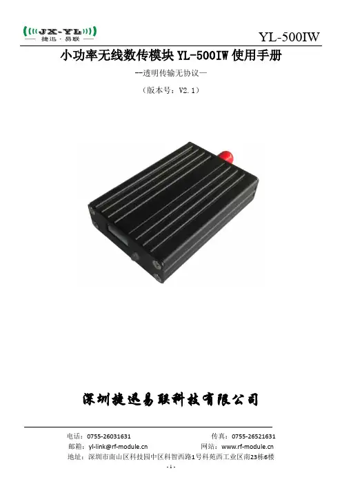
小功率无线数传模块YL-500IW使用手册--透明传输无协议—(版本号:V2.1)深圳捷迅易联科技有限公司电话:*************传真:*************邮箱:********************网站: 地址:深圳市南山区科技园中区科智西路1号科苑西工业区南23栋6楼目录目录 (2)一、产品概述 (3)二、产品特点 (3)三、应用领域 (4)四、尺寸引脚 (5)五、模块参数 (5)六、应用电路 (6)1接线说明 (6)2接线注意事项 (7)七、应用说明 (7)八、参数的配置 (7)(一)模块和电脑连接方法 (8)(二)上位机软件界面 (8)(三)用上位机软件修改参数 (8)(四)参数功能一览表 (9)(五)参数详解 (9)九、数据流介绍 (10)十、AT命令 (10)(一)参数格式 (10)(二)参数详解 (11)1检测电台处理 (11)2读写信道 (11)3读写空中速率 (11)4读写串口速率 (11)5读写ID (11)6写发射功率 (12)十一、组网应用 (12)十二、天线选择 (12)十三、使用须知 (13)1)数据延迟 (13)2)流量控制 (13)3)差错控制 (13)十四、注意事项 (13)十五、故障排除 (13)一、产品概述YL-500IW是一款高稳定性,低功耗,高性价比的无线模块,并且采用GFSK调制方式,增加了无线数据的稳定性。
YL-500IW是透明传输模块,在不改变客户的任何数据和协议的前提,完成无线传输数据功能。
YL-500IW在稳定性上面,软件做了非常多的检测措施,保证模块在任何情况下都不可能出现死机或不工作,完全符合工业级的设计标准。
该模块相对一般模块具有尺寸小,灵敏度高,传输距离远,通讯数率高,内部自动完成通讯协议转换和数据收发控制等特点。
用户可以通过我公司配置的上位机软件根据自己的需求灵活配置模块的串行速率,工作信道,发射功率,通讯数率等参数。
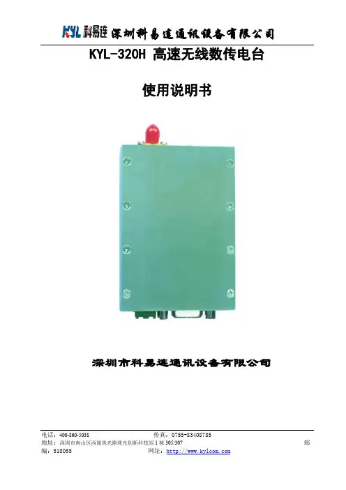
电话:400-860-5038 传真:地址:深圳市南山区西丽珠光路珠光创新科技园1栋305/307 邮KYL-320H 高速无线数传电台使用说明书深圳市科易连通讯设备有限公司尊敬的客户:您好!感谢您使用科易连产品,为了更好更快更有效的使用本产品,请在使用前认真仔细地阅读本说明书。
我公司产品使用方便、功能丰富、接口简单能满足客户多方位的需求。
若有任何技术问题或需要技术支持,请打技术部电话:*************,*************。
一、KYL-320H概述KYL-320H高速率无线数传电台,是一种远距离无线数据传输产品,它体积小,金属外壳,屏蔽性能好,抗干扰性强,内部采用集成功放,TCXO等高可靠性器件,内置看门狗,产品的稳定性及可靠性极高。
采用先进的GFSK调制方式,提高了频率资源的利用率和产品的抗干扰能力,半双功的通讯方式,能方便为用户提供双向的数据信号传输、检测和控制。
收发时间小于18mS(9600bps通讯数率),适时性强。
适合用于无线数据采集、工业控制、油田测控、水纹监测等重要领域。
二、KYL-320H功能特点1.功率及灵敏度射频输出功率大于5W,高接收灵敏度-123dbm(1200bps);-118dbm(9600bps)。
2. 多个工作频段,满足用户多方面需求载频频率400 - 470MHz,也可提供868/915MHz等频率。
3.传输距离远8Km (BER=10-5@9600bps,大吸盘天线,开阔地);12Km (BER=10-5@1200bps,大吸盘天线,开阔地);4.多信道,多速率。
KYL-320H型模块标准配置提供8个信道,满足用户多种通信组合方式的需求。
KYL-320H型模块可提供1200bps、2400bps、4800bps、9600bps、19200bps、38400bps等多种通信波特率。
5.高速无线通讯和大的数据缓冲区。
空中速率大于或等于串口速率时可连续传输无限大的数据,空中速率小于或等于串口速率时,缓冲区暂存后转输。
串口设备CDMA无线联网数传EIC-CC12用户手册北京东方讯科技发展有限公司目录1产品简介 (3)1.1产品特征 (3)1.2 主要功能 (3)1.3 技术规格 (3)1.4 外部接口 (4)1.4.1 电源 (4)1.4.2 指示灯 (4)1.4.3 RS232串口 (4)1.4.4 拨码开关 (5)1.4.5 天线接口 (5)2使用指南 (5)2.1配置前的准备工作 (5)2.2 EIC-CC12配置指南 (6)2.2.1 用串口工具进行配置 (6)2.2.2 用串口设置程序进行配置 (6)2.3 通讯测试 (8)3应用实例 (8)4附录:CC12 AT指令集 (8)1产品简介串口设备CDMA无线联网数传EIC-CC12是一个可以让工业用的RS232/RS485串口设备的串口通信立即转换为CDMA无线网络通信的双向转换传输设备。
转换器采用透明传输的方式,用户不用知道复杂的CDMA通讯原理和TCP/IP、UDP协议,不用更改程序即可实现原有串口设备的无线网络连接,节省您宝贵的时间和已有投资,可用于长距离通信或控制。
广泛用于楼宇自动化控制、停车场设备、交通控制、LED屏幕控制、工厂、车间、矿井、银行、电气等遥控领域。
能快速实现串口设备的遥控功能。
EIC-CC12支持RS232/RS485串口接口,直接连接串口设备使得串口设备立即具备遥控功能。
在两台串口设备之间成对使用EIC-CC12的透明传输模式,相当于延长了串口的通信距离,从而实现串口设备之间的遥控。
1.1产品特征RS232串口速率高达115200 bps串口经济型:三线标准:RXD,TXD,GND现阶段CDMA网络的建设已经成熟,CDMA数据通信具有稳数据传输定、速度快、数据量大的优点。
单程<1秒,速率>100kbps,非常适合图象传输。
支持UDP/TCP网络协议CDMA数据通信变底层的串口协议为广泛使用的TCP/IP协议掉线自动重新拨号功能通过超级终端类似于AT指令方式或设置程序灵活设置通信参数设备之间透明传输/非通明传输支持静态IP、域名、SMS找IP等多种主机发现方式供电:+5V耗电:待发射状态约120mA;发射状态约300mA;范围200mA ~480mA工作温度: -20℃~ +70℃1.2 主要功能实现RS232/RS485串口到CDMA无线网络通信的双向转换,其功能如下:把RS232/RS485串口接收到的数据转为CDMA无线网络发到控制端把CDMA无线网络接收到的控制端数据转为通过RS232/RS485串口发出1.3 技术规格接口:RS232/RS485串口、CDMA天线接口协议:TCP/UDP/IP/ICMP/PPP/PAP/DNS 电源:DC 5V尺寸:113mm ×68mm ×25mm1.4 外部接口1.4.1 电源电源规格为5V(2A)直流电源,芯为正极。
一:900M性能讲解1:读写器在下列环境条件下应能正常工作环境温度:-20℃~70℃;平均相对湿度:不大于95%(+25℃);2:读标签方式通过自动感应方式读标签。
具体读卡方式有:自动连续读卡、触发读卡、定时读卡、控制读卡、3:读标签距离读标签的距离达到10—15m。
4:读取标签协议符合ISO18000-6B,EPC Gen2协议的所有标签均可被识读。
5:标签读写时间读:<12ms。
写:<31ms。
6:具防冲撞功能能够一次性识别多张标签,60张卡/秒7:天线数量两路天线。
(目前只支持两个天线)8:射频工作频率符合ISO/IEC 18000-6标准及中国无线电管理规则。
工作频率范围:902~928MHz。
目前我们国家给定的范围为:920.5M——924.5M。
9:频率误差误差范围≤±150KHz。
(此问题细讲比较深入,如果有客户问可告诉他数值,如果客户问的比较仔细可以转到研发,让研发来具体解答)10:射频工作方式以广谱跳频(FHSS)或定频方式。
(防干扰,在一频率读卡出现干扰时自动跳频到其他频道读卡,从而避免干扰)11:射频输出功率输出功率在15dBm~32dBm之间可调。
(调整通过上位机软件进行调整)12:供电方式及工作电压供电电源为9V,12V的直流电源。
工作电压在9V-12V。
当电池电压在标称值±5%范围内时,读写器应工作正常。
13:工作电流及功耗将射频功率开到最大,最大工作电流<1.5A;不开射频,最小工作电流<0.5A。
工作功耗:最大功耗≤12W。
14:串口通讯(读卡器和道闸间距离)RS232通讯符合EIA-RS232标准。
串口波特率可调,默认为:115200bps,RS232通讯距离15米RS485通讯符合EIA-RS485标准。
波特率可选9600bps、19200bps、115200bps,传输距离可达1200m。
15:网线口通讯符合IEEE802.3标准。

有线数字控制会议系统(HY900MANUAL)产品说明书前言欢迎您使用HiVi惠威会议系统产品。
在安装和使用本产品之前,请您务必仔细阅读随机配送的资料,这会有利于您更好的使用本产品。
未严格按本手册说明操作而导致的错误或造成的任何损失,HiVi惠威将不承担责任。
本手册中的图片仅供参考,如果图片与实际产品不符,请以实际产品为准。
为更好地提供服务,HiVi 惠威保留对本手册中描述的产品和软件程序以及本手册的内容随时更新和修改的权利,恕不另行通知。
本手册内容受著作权法律法规保护,未经HiVi惠威事先书面授权,不得以任何方式复制、抄录本手册,或将本手册内容以任何形式在任何媒体中进行传播,或将本手册翻译成任何文字。
为确保设备可靠使用及人员的安全,请在安装、使用和维护时,严格遵守以下事项:1.为防止火灾或漏电,不要将系统设备置于过冷或过热的地方,请勿将系统设备受雨或受潮,阴雨潮湿天气或长时间不使用时,应关闭设备。
2.会议系统主机的电源在工作时会发热,因此要保持工作环境的良好通风,以免温度过高而损坏机器。
3.非专业人士未经许可,请不要试图拆开设备,不要私自维修,以免发生意外事故、严重导致损坏。
4.安装时确保安全。
使用过程中发现本产品的实际情况与本手册有不一致之处,或您想得到最新的信息,以及您有任何问题或想法,请垂询本公司。
第一章·系统介绍HY900有线全数字会议系统,是HiVi惠威针对现代大、中、小型会议的使用场合而研发设计的专门电子会议设备,具有讨论、表决、同传、签到、服务呼叫、自动摄像跟踪功能;系统采用100M以太网总线,实现会议控制数字化、音频数字化、网络化。
采用稳定性高的嵌入式软件操作系统、专用航空级带螺纹及锁紧接口的接插电缆,完全胜任工程严柯施工要求和长时间会议使用考验。
系统遵循HiVi自主专利的会议控制协议(HCCP)与音频流协议(HCAP),具备在线升级功能,维护升级智能化。
系统特色:1.支持单元即插即用,随时增加会议单元与会,会议管理简洁高效;2.支持单元热插拔,不影响在线会议单元,有效保障会议正常进行;3.单元链路节点记忆,单元掉电在原链路节点重新上电可以继续工作;4.集中供电和分布供电的新特性,满足不同工程施工和布线的需要,为工程提供灵活多样的解决方案;5.具有单独的会场全景摄像图像输出功能,在一般的会议发言摄像跟踪基础上,为会议提供更周到、更全面的会场摄像跟踪解决方案。
无线烟雾报警器产品型号:YL-102版本:V1.3更新日期:2019-12-20目录一、产品简介 (3)二、报警器规格参数 (4)三、报警器结构尺寸(mm) (5)四、安装方式及注意事项 (5)1、安装说明: (5)2、注意事项: (5)五、报警器功能说明: (5)1、火灾报警功能: (5)2、模拟报警功能: (5)3、更换电池: (6)4、联网功能说明: (6)包装清单 (6)保修指南 (6)一、产品简介光电感烟火灾探测报警器(以下简称:报警器)是一款通过烟雾来探测火灾的报警器,当烟雾产生并达到一定浓度时,报警器将发出声光报警信号,提醒您采取相应措施,有效的保护您和家人的生命及财产安全。
无线数据传输采用LoRa和NB-IoT两种方案:LoRa方案(YL-102L):基于Semtech的低功耗远距离LoRa扩频无线数传方案Sx1278,具备休眠无线唤醒功能,信号覆盖1km。
NB-IoT方案(YL-102N):基于MTK高性能NB-IoT芯片,全网通网络制式,适应三大运营商网络,低功耗设计,通过NB基站,数据直接上传到用户云平台。
全电子编码,可通过无线远程编码现场改写,单片机实时采样处理数据、并能保存最近历史数据,跟踪现场情况。
具有温度、湿度、灰尘积累漂移补偿,报警器失效检测功能(故障上报控制器)。
采用上、下盖结构设计,独立底座安装,安装、调试、维护简单方便。
可LoRa(LoRaWAN)、NB-IoT 等无线通讯技术联网,监测管理,安装、维护方便。
广泛适用于住宅小区,写字楼,商场,酒店,仓库、档案馆、博物馆等监测报警的物联网应用场景。
二、报警器规格参数规格参数LoRa方案NB-IoT方案通讯频率433MHz、490MHz 全网通网络制式通讯距离开阔地视距1km有NB-IoT信号覆盖,无限制供电方式内置高性能一次性锂电池(3.6V)工作电流休眠电流:10uA发送数据时电流:<120mA休眠电流:20uA 联网时电流:<700mA 上报数据时电流:<300mA检测周期3秒,红色指示灯闪烁一下基本功能每三小时上报一次心跳包,报告报警器状态检测有烟雾时,触发蜂鸣器报警连响20秒,同时连续三次上报数据到云平台带自检按键,可模拟检测报警器状态参数设置UART-TTL(Mini-USB接头形式)或无线连接配置壳体材料阻燃ABS (V0),白色尺寸重量直径90mm,高36mm(带底座),70g(含电池)安装高度<12m,保护面积:<80平米,使用环境室内,温度-10℃-+55℃,相对湿度95%(40℃士2℃无凝露)执行标准GB4715—2006,型号:JTYJ-GD-01LM/BW具体参考国标GB50116--98《火灾自动报警系统设计规范》中相关规定Φ90mm 37mm三、报警器结构尺寸(mm)四、安装方式及注意事项1、安装说明:1)螺钉安装方式2)将电池装入电池仓,按住消音/自检按钮约1秒确认指示灯红灯闪烁一次,蜂鸣器鸣叫一次。
WDA-900L扩音器(移动音箱)Amplifier (Mobile speaker)用户手册User Manual01主机型号:WDA-900L 功放类型:D类额定功率:80W 低音:10英寸35芯120磁4Ω高音:25芯 80磁4Ω 频率响应:80Hz-15KHz电源电压:AC 100V-240V /50Hz-60Hz 内置电池:11V /10000m Ah可充电锂电池工作时间:3-6小时充电时间:3-5小时 标准配置:WDA-900L音箱×1 遥控器×1UHF无线麦克风×2 AC电源线×1AA电池×4 AAA电池×2UHF天线×2 说明书×1总谐波失真 ≤0.5%UHF频率范围:640MHz-690MHz 无线麦克风灵敏度:-80dBm 无线麦克风频率响应:100Hz-10KHz 无线麦克风使用距离:50M(空旷地带)无线麦克风电池使用时间:10小时工作温度:-10℃-45℃主机体积(长*宽*高):300*310*520mm 重量:净重15Kg 多功能、大功率有源音箱系统,音频输出功率高达80W;配置UHF双通道无线麦克风,传输更可靠,可多套同时使用;具有多路独立音量控制和EQ音效、ECHO混响调节,适应多种场所的使用需求;具有音乐播放功能,支持U盘和SD存储卡上的多媒体音频文件播放;具有蓝牙功能,可连接手机、电脑、PAD等蓝牙设备播放音乐;具有音乐原声消唱功能,随时随地体验卡拉OK; 配置3.5mm、RCA音频接口和有线麦克风接口,方便连接外部音源和有线麦克风输入;内置大容量11V /10000m Ah可充电锂电池,适用于户内或户外场合使用;尊敬的用户: 感谢您选购TAKSTAR WDA-900L有源移动音箱,WDA-900L是一款集有线/无线两用、多功能、大功率有源移动音箱。
采用双通道UHF设计,可两支麦克风同时使用。
LBI-38163CMaintenance Manual EDACS®900 MHz TRUNKED RECEIVER 19D902120G1ericssonz Ericsson Inc.Private Radio SystemsMountain View RoadLynchburg, Virginia 245021-800-528-7711 (Outside USA, 804-528-7711)Printed in U.S.A.Copyright© December 1989, General Electric CompanySPECIFICATIONS*Frequency Range 896.0125 — 900.9875 MHzAudio OutputAUDIO PA 2 Watts at 8 OhmsV ol/ Squelch Hi ***************************************Selectivity 75 dB adjacent channel Spurious ResponseImage - 80 dB minimum All Other - 90 dB minimumIntermodulationAdjacent Channel- 65 dB Alt. Channel and Beyond - 80 dB12 dB SINAD - 120 dBm typical Rated OutputAudio Board 19D902181G1 2 Watts Audio Board 19D902093G1 5 Watts Distortion Less than 5%Frequency Stability 0.05 PPM (high stability reference)AM Rejection- 26 dB minimum Hum and Noise- 40 dB *These specifications are intended primarily for use by service personnel. Refer to the appropriate Specification Sheet for complete specifications.This manual covers Ericsson and General Electric products manufactured and sold by Ericsson Inc.NOTICE!This manual is published by Ericsson Inc., without any warranty. Improvements and changes to this manual necessitated by typographical errors, inaccuracies of current information, or improvements to programs and/or equipment, may be made by E ricsson Inc., at any time and without notice. Such changes will be incorporated into new editions of this manual. No part of this manual may be reproduced or transmitted in any form or by any means, electronic or mechanical, including photocopying and recording, for any purpose, without the express written permission of Ericsson Inc.Repairs to this equipment should be made only by an authorized service technician or facility designated by the supplier.Any repairs, alterations or substitution of recommended parts made by the user to this equipment not approved by the manufacturer could void the user’s authority to operate the equipment in addition to the manufacturer’s warranty.NOTICE!LBI-381631DESCRIPTIONThese receivers are double conversion, superheterodyne, single frequency FM receivers for operation in trunked re-peater systems. The receiver utilizes monolithic crystal filters between the IF gain stages to provide the selectivity and intermodulation required to meet or exceed all EIA specifica-tions for trunked receivers.The receiver consists of the receiver board and audio board, with audio and control functions as well as supply voltages applied through the system board.CIRCUIT ANALYSIS RECEIVER BOARDThe receiver board consists of the RF amplifier, mixer and 1st IF, 2nd IF and audio stages, and a synthesizer circuit. The receiver board uses a combination of crystal and ceramic bandpass filters for good intermodulation and desensitization characteristics. A Block Diagram of the receiver board is shown in Figure 1.RF Front EndRF signal input from the antenna is applied to the receiver board through J1. The 896-901 MHz input is coupled through broadband ceramic filter FL1 to RF amplifier, U1. Amplifier U1 provides a gain of approximately 23 dB.The amplifier output is coupled through two broadband ceramic filters (FL2 and FL3) and applied to Mixer U2. The mixer is a high level passive switch with a loss of approxi-mately 6.5 dB.First Mixer And IFThe local oscillator (LO) injection for the mixer is gener-ated by the receiver synthesizer located on the exciter board. The 826-831 MHz LO signal from the exciter is applied to the receiver board at J4, where it is amplified to approximately 100 milliwatts by RF Amp U3, filtered by FL4, and applied tothe 1st mixer.The 70 MHZ mixer output is amplified by Q6 and IFAmplifier U4. Two 70 MHz crystal filters, FL5 and FL6,provide the 1st IF filtering.SynthesizerA synthesizer circuit located on the receiver board providesthe 2nd LO frequency of 70.450 MHZ. The synthesizer con-sists of counter U9, phase detector U10, DC amp U11, VCOFET Q3, RF buffer amplifiers Q1, Q2 and Q4.The high stability 17.6125 MHz reference frequency fromthe master oscillator is applied to the receiver board at J2. Thisreference frequency is buffered by Q1, and applied to phasedetector U10.VCO Q3 operates at 70.450 MHz. The circuit is tuned byL11. The output of the VCO is coupled through buffer amp Q4and RF amp Q2, and applied to the divide-by-four counter, U9.The counter output is applied to phase detector U10, whoseoutput is applied to DC amplifier U11. Feedback for the loopcontrol voltage is developed across R7.The 70.450 MHz output is coupled through C40 from thecollector of Q4 to pin 4 of audio IC, U6, , where it is mixedwith the 70 MHZ 1st IF input to derive the 455 kHz 2nd IF.Second Mixer, IF & AudioIntegrated circuit (IC) U6 contains the 2nd mixer, 2nd IFamplifier and mixer stages, the audio detector and audio am-plifiers.The 70 MHz 1st IF output of FL6 is applied to U6-1. The70.450 MHz 2nd LO signal is applied to the 2nd mixer at U6-4to derive the 450 kHz 2nd IF signal. The 450 kHz IF is filteredby ceramic filters FL7 and FL8. The audio component of the2nd IF is demodulated by the quadrature detector circuit in U6.Network Z1 provides the required 90° phase shift of the 450kHz signal. The de-modulated audio from U6-8 is coupledthrough buffer Q5 and applied to audio output jack J3-3.RSSI VoltageThe Received Signal Sensitivity Indication (RSSI) is a DClevel that is proportional to the receiver RF input signal levelto the receiver. This voltage can be measured at J3-4.Supply VoltageThe receiver is supplied by a regulated 10 volts from thesystem board. However, the more critical circuits are suppliedby voltage regulators U5, U7 and U8 for stability and isolation.Regulated 10 volts from the system board is used to supplyRF amplifier U1, IF amp U4, VCO transistor Q3, and RF bufferQ4. Regulator U5 provides the 5-volt supply for audio IC, U6,and 5-volt regulator U7 supplies counter U9, Phase detector U10,and RF amps Q1 and Q2. The 8-volt regulator (U8) providespower for RF amp U3 and audio buffer Q5.AUDIO BOARDAudio board 19D902181G1 consists of a preamplifier cir-cuit, squelch detector, audio IC and audio PA circuit. The audioboard is connected to the system board through P904. Thediscriminator output is connected through J601-3 on the audioboard. Power is supplied from a regulated 10 volts from thesystem board. A Block Diagram Of the audio board is shown inFigure 2.Audio PreamplifierDiscriminator audio from J602-3 is coupled through AudioLevel Adjust R608 to the preamplifier circuit. The preamp con-sists of Q601, Q602, Q605 and associated circuitry, and provides26 dB of gain. The amplified output is connected to the squelchand audio hybrid ICs through the arm of the VOL and SQ controlson the exciter-receiver door assembly.Receiver AudioThe audio circuitry consists of a three-stage, quad integratedcircuit (U602-A, U602-C and U602-D). The three stages providea standard EIA Channel Guard tone reject filter, a receiverde-emphasis circuit, and the low level audio driver circuitry.Audio from the pre-amplifier circuit is coupled through theVOLUME control to VOLUME arm (P904-13). The audio atP904-13 is applied to CG tone reject filter U602-C, U602-D andassociated circuitry to remove any low frequency signal. Thefilter output is then applied to a 6-dB per octave de-empha-sis/audio driver circuit (U602-A). The audio driver output isAC-coupled to the Class AB audio PA integrated circuit, U604-1.The PA output is coupled through C633 to provide ratedpower to the 8-ohm speaker. Feedback from U604-3 is coupledthrough R652 and C630 to determine the gain of the audio poweramplifier. Capacitor C634 is connected across the output toprotect U604 from a "no load" or open circuit condition.Receiver SquelchAudio SwitchesU606 is a dual section, audio switching IC that acts as twoform "C" (N.O.- N.C.) contacts. The switch states are controlledby the inputs at U606A-10 and U606B-11. Both of the inputs areactivated by the receiver SQ DISABLE function.When the receiver is squelched, pin 11 of U606-A is near A-.This turns off the entire audio circuit to eliminate noise. Pin 1 ofU606-B is connected to the system board through P904-7 (RXMUTE). This allows the receiver audio to be disabled by theChannel Guard option when used.Pin 2 of U606-10 is connected to the system board throughP904-6 (SQ DISABLE) so that the receiver audio stages can beactivated for an alert tone output whenever the Carrier ControlledTimer or other options are used.Squelch ICsThe receiver squelch circuit consists of noise amplifierU602B, active noise filter U601C and U601D, noise rectifierU601B, DC amp U601A, and level detector U603D. In addition,the squelch circuit contains the Receiver Unsquelched Sensor(RUS) switch U603B, Carrier Activity Sensor (CAS) switchU603A, and the RX MUTE switch U603C. The RX MUTEswitch controls the audio path to audio IC U604 through U606.Noise Amp, Filter & Level DetectorNoise from the limiter/detector at P904-10 is coupled to thenoise amplifier U602B through the SQUELCH control, and thenapplied to the active noise filter (U601C and U601D). The activefilter provides the gain and selectivity necessary to distinguishbetween noise and audio. The filter output at U601D-14 drivesthe level detector circuit to provide the squelch switching func-tions. Potentiometer R622 adjusts the noise level for the propersquelch operation.Squelch SwitchesLevel detector U603D controls two of the switched squelchoutputs. The first output controls the RX MUTE switch (U603C),and the second output controls the CAS switch (U603A). TheRUS switch (U603B) is also controlled by the RX MUTE signal.The squelch input to the level detector is at U603D-10.U603D-11 is referenced to 4 V olts from voltage divider R640 andR641. When the receiver is squelched, the input at U603D-10 isnear 3 V olts, and the output at pin 13 is approximately 10 V olts.This keeps the output of receiver audio stages turned off, mutingthe audio. The level detector output is connected to its inputthrough R639, providing a hysteresis loop in the squelch circuitto prevent squelch closing on weak signals.When the receiver is quieted by an on-frequency signal(receiver unsquelches), the voltage at U603D-10 rises to approxi-mately 5 V olts DC, and the output at pin 14 drops to near 0 volts.This turns on the audio stages and sound is heard at the speaker.RUS Switch (Receiver Unsquelched Sensor)LBI-38163 2Figure 2 - Block Diagram; Audio Board 19D902181G1Figure 1 - Receiver Board Block DiagramLBI-381633When the receiver is unsquelched, the output of the level detector (U603D-13) goes low. The low turns off U603C, causing U603B-1 to go high (approximately 10 Vdc), turning on RUS switch U603B. The RUS output at U603B-1 is also connected to the system board through P904-8 for use in special applications.CAS Switch (Carrier Activity Sensor)Level detector U603D also drives CAS switch U603A. When the receiver unsquelches, the voltage at U603A-2 rises to approximately 10 volts. This voltage is connected to the system board through P904-9 where it is used to activated such options as the Channel Busy light, Carrier Control Timer, and Carrier Operated Relay.AUDIO BOARDAudio board 19D902093G1 consists of a preamplifier circuit, squelch detector, audio IC and audio PA circuit. The audio board is connected to the system board through P904. The discriminator output is connected through J601-3 on the audio board. Power is supplied from a regulated 10 volts from the system board. A Block Diagram of the audio board is shown in Figure 3.Audio PreamplifierDiscriminator audio from J602-3 is coupled through Audio Level Adjust R608 to the preamplifier circuit. The preamp consists of Q601, Q602, Q605 and associated circuitry, and provides 26 dB of gain. The amplified output is connected to the squelch and audio hybrid ICs through the arm of the VOL and SQ controls on the exciter-receiver door assembly. Audio ICHybrid audio IC U604 contains a standard EIA Channel Guard tone reject filter, a receiver de-emphasis circuit, and the low level audio drivers.Audio from the VOLUME control arm is coupled through P904-13 to pin 4 of the audio IC. The audio at U604-4 is applied to a Channel Guard tone reject filter to remove any low level signal. The filter output is then applied to a 6-dB per octave de-emphasis circuit. The de-emphasized output is cou-pled through C635 to the differential audio driver circuit.The driver output is DC-coupled to the base of push-pull audio PA amplifiers Q603 and Q604. The PA output is coupled through audio transformer T601 to provide rated power to the 8-ohm speaker. Feedback from windings T601-3 and -4 deter-mine the gain of the differential audio driver in U604. Resistor R619 and capacitor C637 in the transformer secondary protect the PA transistors from a "no load" or open circuit conditions.When the receiver is squelched, U604-1 drops to near A-.This turns off the entire audio circuit to eliminate current drain.Pin 1 of U604 is also connected to the system board throughP904-7 (RX MUTE). This disables the receiver audio when-ever the Channel Guard option is used.Pin 2 of U604 is connected to the system board throughP904-6 (SQ DISABLE) so that the receiver audio stages canbe activated for an alert tone output whenever the CarrierControlled Timer or other options are used.Squelch ICSquelch hybrid U603 contains the noise amplifier, activenoise filter, detector, slow and fast squelch circuits, the Re-ceiver Unsquelched Sensor (RUS), and the Carrier ActivitySensor (CAS) switch.Noise from the quadrature detector is coupled through theaudio preamp to the SQUELCH control,and then throughP904-10 to pins 1 and 2 on Squelch IC U603. The input is thenapplied to the noise amplifier and active filter to provide thegain and selectivity necessary to distinguish between noise andaudio. The filter output is applied to external noise amplifierU601 which provides the extra noise gain required for narrowband signals. The amplifier output at U601-1 drives the activedetector circuits in U603 to provide the squelch switchingfunctions.Thermistor RT601 keeps the input to the active detectorconstant over wide variations in temperature. R622 is used toset the noise level for proper squelch operation.With a signal below the 20 dB quieting level, the slowsquelch circuit provides a conventional (200 millisecond) slowsquelch operation to prevent rapid squelch opening and clos-ing in weak signal areas. Service Note: In station applica-tions,the fast squelch function is disabled by removing C360.RX MuteThe squelch RX MUTE output at U603-7 is connected topin 1 of audio IC, U604. When the receiver is squelched, theoutput at U603-7 is near A-. This keeps the differential audiodriver turned off, muting the receiver.When the receiver is quieted by an on-frequency signal(receiver unsquelches), the voltage at U603-7 rises to approxi-mately 10 volts. This turns on the audio driver and audio PAso that sound is heard at the speaker.RUS Switch (Receiver Unsquelched Sensor)With the receiver unsquelched, the output of the squelchswitch in U603 turns on the RUS switch. Th RUS switchoutput is connected to the noise amplifier stage, providing thehysteresis loop in the squelch circuit. The RUS output (whenunsquelched) increases the gain of the noise amp, ppreventingsquelch closing on weak signals. The RUS output at U603-8 isalso connected to the system board through P904-8 for use inspecial applications.CAS Switch (Carrier Activity Sensor)The squelch in U603 also drives the CAS switch in the IC.When the receiver unsquelches, the voltage at U603-6 rises toapproximately 10 volts This voltage is connected to the systemboard through P904-9 where it is used to activated such optionsas the Channel Busy light, Carrier Control Timer, and CarrierOperated Relay.Figure 3 - Block Diagram; Audio Board 19D902093G1LBI-38163 4MAINTENANCE SERVICINGTo gain access to the receiver for servicing, refer to the following procedure (see Figure 4).To service the receiver from the top:1.Turn the two latching knobs "A" counterclockwise tounlatch the radio housing door as shown in Figure 4.2.Swing the radio housing down as shown in Figure 5 andremove the top cover.To service the receiver from the bottom:1.Turn the two latching knobs "A" counterclockwise tounlatch the radio housing and swing the housing downas shown.2.Remove the top cover. Then grasp the receiver handle"B" and swing the housing up for access to the bottomof the receiver.There are only four controls that require adjustment duringsystem adjustment. Refer to the system adjustment procedurecontained in GETC Maintenance Manual, LBI-38164.TROUBLESHOOTINGBoth the Schematic and Outline diagrams contain trou-bleshooting information to assist in servicing the receiver. Thisservice information includes voltage and gain readings, powerlevels and signal flow information. Refer to these diagrams whentroubleshooting the receiver (see Table of Contents).ADJUSTMENTSThe receiver has no adjustments for "peaking" up receiverperformance. If some adjustment is required as a result of com-ponent replacement or other maintenance, refer to the Adjust-ment Procedure listed in the Table of Contents.Figure 3 - Access To Knobs Securing Door Figure 4 - Access To Receiver (Top and Bottom)LBI-381635ADJUSTMENT PROCEDUREThe receiver has no field adjustments for peaking up performance. However, should it become necessary to replace components at the customer location, the following adjust-ments may be required.Calibration of the 70.45 MHz 2nd L.O.(L11):1.Remove the top cover of the receiver, and then discon-nect the 17.6125 MHz reference signal from J2.2.Measure for 70.45 MHz æ50 kHz at J5. If necessary,carfefully adjust L11 to obtain 70.45 MHz æ50 kHz(see CAUTION below).Figure 5 - Typical RF Levels vs. RSSI Voltages Receiver BoardCalibration of Quadrature Detector Z1:1.Remove the receiver top cover. Then apply a modu-lated RF signal to antenna jack J1.2.Adjust the RF generator for -50 dBm with 1 kHz tone at 1.5 kHz modulation.3.Adjust Z1 for maximum audio at J3-3 (200 mV rms minimum). Then adjust Z1 counter-clockwise until the audio level drops 1 dB.4.Fine tune Z1 for symmetrical eye pattern at J3-3 with input signal modulated with 9600 b/s data at 1.8 kHz peak deviation.ADJUSTMENT PROCEDUREAUDIO BOARD 19D902093G1RC-7058MADE FROM 19D902093AUDIO BOARD 19D902118G1(19D902181, Sh. 1, Rev. 0)RECEIVER BOARDRC-7057AMADE FROM 19D902083 SH. 3, REV . 2LBI-381636OUTLINE DIAGRAMRECEIVER BOARD19D902083G1TOP VIEW(19D902083, Sh. 3, Rev. 2)BOTTOM VIEW(19D902083, Sh. 4, Rev. 2)LBI-381637LBI-38163SCHEMATIC DIAGRAMRECEIVER BOARD19D902083G1(19D902107, Rev. 5)8OUTLINE DIAGRAM AUDIO BOARD 19D902093G1AUDIO BOARD 19D902181G1(19D902181, Sh. 1, Rev. 0)(19D902182, Sh. 1&2, Rev. 3)(19D902093, Sh. 1, Rev. 0)(19A705508, Sh. 1&2, Rev. 0)LBI-381639SCHEMATIC DIAGRAMLBI-38163AUDIO BOARD19D902181G1(19D902183, Sh. 1, Rev. 1)SCHEMATIC DIAGRAM(19D902112, Sh. 1, Rev. 1)AUDIO BOARD 19D902093G1LBI-38163LBI-38163PARTS LISTLBI-38163 PARTS LISTPRODUCTION CHANGESChanges in the equipment to improve performance or to simplifycircuits are identified by a "Revision Letter," which is stamped after themodel number of the unit. The revision stamped on the unit includesall previous revisions. Refer to the Parts List for description of partsaffected by these revisions.Rev. A - Receiver Board 19D902083G1Incorporated into initial shipment.Rev. B - Receiver Board 19D902083G1T o improve T est reading at J5. Changed R3.R3 was: 19D800607P101; Metal Film, 100 ohms æ5%, 1/8w.Rev. C - Receiver Board 19D902083G1T o improve audio frequency response for high speed dataapplications, capacitor C22 was changed to 19A702061P45(47 pF) and transistor Q5 was changed to NPN Darlington344A3104P1. Capacitor C56 19A702061P75 (390 pF) andcoil L17 19A700024P43 (330 uH) were added between pinU6-8 and Q5 base.C22 was: 19A702061P77; 470 pF.Q5 was: 19A700023P2; NPN; sim to 2N3904.Rev. D - Receiver Board 19D902083G1T o permit 9600 baud operation.Printed wire board changed.Deleted C8, C11, C24, L7 and L9.C6 was 220 pF (19A702061P69).C10 was 10 pF (19A702061P13).C23 was 1000 pF (19A702052P5).R23 was 220K ohm (19B800607P224).U4 was 19A705538P1.C3 was 1000 pF (19A702052P5).L2 was 10 uH (19A700024P25).L15 was 100 nH (19A700024P1).FL5 was 19A705548G2.FL6 was 19A705548G1.FL7 was 19A705580P1.Added C57 thru C61, L18 thru L20, and R25 thru R27.。
数字电台配件参数及需求1. 配件参数要求1)电池1.1 要求电池必须为摩托罗拉MTP850手持对讲机原厂配件(参考型号PMNN4351)1.2 电池容量应当在1800mAh以上1.3 电池应当通过MIL810E测试1.4充电模式应支持初次充满,快充,慢充和维护充电。
满足各种日常工作需要1.5 放电适用温度范围应满足-10℃至+60℃,适合在恶劣环境下工作1.6电压范围应满足3.0V(完全放电)到4.2V(充1.7电池化学性质应为锂离子1.8尺寸在长78毫米×宽46毫米×厚度15毫米以内1.9外壳材质应满足PC,B级阻燃1.10抗静电应符合IEC/EN61000-4-21.11抗跌落应该达到距表面48英寸,边和角26次跌落测试2)充电器摩托罗拉MTP850专用充电器,要求与MTP850及其电池完全匹配。
●充电器包含双联桌面充电器FTN6575以及旅行充电器(电源)NNTN7558,插头可直接适用于中国适配器。
3)耳机防尘/水等级达到IP54适用温度范围应满足-30℃+65℃,适合在恶劣环境下工作双线空气导管耳机ACH2042技术需求●空气导管耳机技术需求:●应为MTP850电台专用空气导管耳机;●空气导管应采用高级声学空气导管,外观小巧且佩戴舒适;●线材应内含防弹材料kevlar的环保PU线材,结实耐用;●扬声器灵敏度不低于111±3dB at 1000Hz;●扬声器阻抗不高于90±15 Ohm;●麦克风灵敏度不低于-40dB±2dB at 1000Hz(0dB=1V/Pa);●麦克风阻抗不高于2.2kOhm。
功能特点:高级声学导管,外观小巧且佩戴舒适;内含防弹材料kevlar的环保PU线材,结实耐用;产品品质符合军用标准单线耳挂式耳机韶音EWS2000技术需求:应为MTP850电台专用耳挂式耳机;耳挂部分应由TPE环保材料制成,柔韧不伤皮肤;线材应内含防弹材料kevlar的环保PU线材,结实耐用;扬声器灵敏度不低于105±3dB at 1000Hz;扬声器阻抗不高于32±15% Ohm at1000Hz;麦克风灵敏度不低于-40dB±2dB at 1000Hz(0dB=1V/Pa);麦克风阻抗不高于2.2kOhm。
--V1.2T10L 无线PLCDESCRIPITION OF PRODUCTSF0020E北京捷麦顺驰科技有限公司 ***************目录1.无线数传电台信道概述 (4)1.1 基本工作原理 (4)1.2 频率与频点 (4)1.3 电台地址寻址方式 (4)2.参数设置和编程连接 (6)2.1 参数说明 (6)2.2 设置操作 (7)2.3 编程连接 (8)2.4 工程下载 (8)3.编程操作 (11)3.1 信道初始化 (11)3.2 接收 (13)3.2.1 包结构 (13)3.2.2 用户接收处理 (13)3.2.3 电台接收完成事件 (14)3.2.4 相关系统变量/函数清单 (17)3.2.5 示例 (17)3.3 发送 (19)3.3.1 电台广播式发送字符串 (20)3.3.2 电台广播式发送数据块 (21)3.3.3 电台指定式发送字符串 (22)3.3.4 电台指定式发送数据块 (23)4.辅助功能 (25)4.1 无线电接收信号强度指示RSSI (25)4.2 电台信道通信测试 (27)24.2.1 回传测试01 (28)4.2.2 响应测试02 (31)4.2.3 请求发送1010 03 (32)4.2.4 测试接收信号强度04 (32)4.2.5 测试周围环境干扰信号强度05 (33)5.附录 (34)5.1 系统变量清单 (34)5.2 电台信道相关系统函数清单 (37)5.3 SM寄存器清单 (38)5.4 电台无线信道指令盒清单 (41)5.5 中断事件编号表 (43)5.6 透传电台编程实例 (44)5.6.1 C语言 (44)5.6.1 梯形图 (45)5.6.1 STL (46)5.7 产品家族介绍 (47)5.8 相关文档及阅读指南 (49)5.9 版权声明 (50)5.10 免责声明 (50)5.11 技术支持 (50)5.12 变更历程 (51)31. 无线数传电台信道概述T10L无线PLC内部集成了430M无线数传电台通信信道。
KYL-668无线数传电台使用说明书深圳市科易连通讯设备有限公司电话:400-860-5038尊敬的客户:您好!感谢您使用科易连产品,为了更好更快更有效的使用本产品,请在使用前认真仔细地阅读本说明书。
无论用户在设备选型期间或在数传电台应用开发的过程中,科易连公司承诺提供全方位的售前、售后技术支持。
用户购买产品之日起科易连公司提供一年保修,终生维护的售后服务。
另外,本公司还可为客户订购开关电源、避雷器和各类天线等配套设备。
一、KYL-668概述深圳市科易连通讯设备有限公司专业生产无线通信产品,KYL-668采用先进的频率合成技术,CPU锁相环控制,配合调制解调器,可提供语音或数据信号的透明传输,能适应各种点对点、点对多点的无线数据通信方式,具有发射功率大、传输距离远、收发一体、安装方便、使用简单、性价比高、低误码率、稳定可靠等特点,应用于远程数据传输及语音对讲系统之中,是一般有线系统的更新换代产品。
具体的应用领域有:船舶、城市交通、出租车对讲系统、工业自动化控制、电力调度、水利工程监控、铁路采集信号传输、采油输油测控、油井水井计量、水情水文监测、气象资料传输、环保监测设备、仓储货柜管理、商场超市理货、林业防护设施、无线信标、江河航运、地质勘探、GPS定位信息、军事训练、公安报警、医疗监护、遥控遥测等自动化控制领域。
二、KYL-668功能特点1.发射功率内部采用进口功放模块,发射功率25W可调,体积108mm×128mm×28mm。
2.ISM频段工作频率,无需申请频点载频频率150/230/450MHz等载频,可存储多达256个频道。
3.高抗干扰能力和低误码率基于MSK的调制方式,采用高效通信协议,在信道误码率为10-2时,可得到实际误码率10-5~10-6。
4.可传输语音或数据信号,作为无线车载对讲电台使用。
电话:400-860-50385.透明的数据传输。
提供透明的数据接口,能适应任何标准或非标准的用户协议。