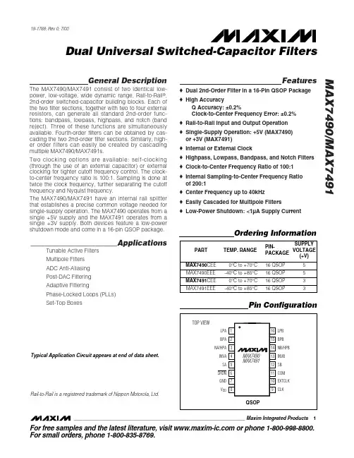
KKA7496L中文资料
- 格式:pdf
- 大小:446.20 KB
- 文档页数:8
TECHNICAL DATAKKA7496L2W+2W AMPLIFIER WITH DC VOLUME CONTROLDESCRIPTIONThe KK A7496L is a stereo 2W+2W class AB power amplifier assembled in the @ Powerdip 14+3+3 package, speciallydesigned for high quality sound, TV and Monitor applications. Features of the KK A7496L include linear volume control, Stand-by and mute functions.• 2W+2W OUTPUT POWERRL = 8Ω @THD = 10% Vcc = 14V• ST-BY AND MUTE FUNCTIONS )• LOW TURN-ON TURN-OFF POP NOISE• LINEAR VOLUME CONTROL DC COUPLED WITH POWER OP. AMP.• NO BOUCHEROT CELL• NO ST-BY RC INPUT NETWORK• SINGLE SUPPLY RANGING UP TO 15V • SHORT CIRCUIT PROTECTION• THERMAL OVERLOAD PROTECTION • INTERNALLY FIXED GAIN • SOFT CLIPPING• VARIABLE OUTPUT AFTER VOLUME CONTROL CIRCUIT • POWERDIP (14+3+3) PACKAGEBLOCK DIAGRAMAbsolute Maximum RatingsSymbol Parameter Value UnitVs DC Supply Voltage 26 VV IN Maximum Input Voltage 8 VppT amb Ambient Operating Temperature 0 to 70 ºCT stg, Tj Storage and Junction Temperature -40 to 150 ºCV6Volume CTRL DC voltage 7 VPIN CONNECTIONELECTRICAL CHARACTERISTICS (Refer to the test circuit Vs = 14V, R= 80Ω,Rg = 50 Ω, Tam = 25ºC)LSymbol Parameter TestTyp Max UnitCondition MinVs Supply Voltage Range 10 18 VIq Total Quiescent Current 25 50 mADC/Vos Output DC Offset Referred toNo Input Signal 200 mV SVR PotenialVo Quiescent Output Voltage 7 VPo Output Power THD = 10%, R L = 8Ω 1.62 WTHD = 1%, R L = 8Ω 1.3 W THD Total Harmonic Distortion Gv = 30dB, Po = 1W, f = 1KHz 0.4 %I peak Output Peak Current (internally limited) 0.7 0.9 AV in Input Signal 2.8 VrmsGv Closed Loop Gain Vol Ctrl > 4.5V 28.5 30 31.5 dBG vLine Monitor Out Gain Vol Ctrl > 4.5V, Zload > 30KΩ-1.5 0 1.5 dBVol Ctrl < 0.5V 80 dBA Min V OL Attenuation at MinimumVolumeBW 0.6 MHzELECTRICAL CHARACTERISTICS (continued)Symbol Parameter TestConditionMinTyp Max Unite N Total Output Noisef = 20Hz to 22KHzPlay, max volume 500800µVf = 20Hz to 22KHz Play, max attenuation 100250µVf = 20Hz to 22KHz Mute 60 150µVSR SlewRate 5 8 V/µsR i Input Resistance 22.5 30 KΩR Var Out Variable Output Resistance 30 100ΩR load Var Out Variable Output Load 2 KΩSVR Supply Voltage Rejection f = 1kHz, max volumeC SVR = 470µF, V RIP = 1V rms35 39 dBf = 1kHz, max attenuationC SVR = 470µF, V RIP = 1V rms55 65 dB T M Thermal Muting 150 ºC T s Thermal Shut-down 160 ºC MUTE STAND-BY & INPUT SELECTION FUNCTIONSV ST ON Stand-by ON Threshold 3.5 VV ST OFF Stand-by OFF Threshold 1.5V V M ON Mute ON Threshold 3.5 VV M OFF Mute OFF Threshold 1.5VI qST-BY Quiescent Current @Stand-by 0.61mAA MUTE MuteAttenuation 50 65 dBI stbyBIAS Stand-by bias current Stand by on V ST-BY = 5VV MUTE = 5V 80 µAµAPlay or Mute -20 -5 µA I muteBIAS Mute bias current Mute 1 5µAPlay 0.22µA APPICATION SUGGESTIONSThe recommended values of the external components are those shown on the application circuit of figure 1A.Different values can be used, the following table can help the designer.COMPONENT SUGGESTIONVALUE PURPOSE LARGERTHANSUGGESTIONSMALLER THANSUGGESTIONR1 300K Volume control circuit Larger volume regulationtime Smaller volume regulation timeR2 10K Mute time constant Larger mute on/off time Smaller mute on/off timeP1 50K Volume control circuitC1 1000µF Supply voltage bypass Danger of oscillationC2 470nF Input DC decoupling Lower low frequency cutoff Higher low frequency cutoff C3 470nF Input DC decoupling Lower low frequency cutoff Higher low frequency cutoff C4 470µF Ripple rejection Better SVR Worse SVRC5 100nF Volume control timeconstant Larger volume regulationtimeSmaller volume regulationtimeC6 1000µF Output DC decoupling Lower low frequency cutoff Higher low frequency cutoff C7 1µF Mute time constant Larger mute on/off time Smaller mute on/off timeC8 1000µF Output DC decoupling Lower low frequency cutoff Higher low frequency cutoff C9 100nF Supply voltage bypass Danger of oscillationFigure 1 A. Application CircuitMUTE STAND-BY TRUTH TABLEOPERATINGCONDITIO MUTE ST-BYH H STANDBYL H STANDBYH L MUTEL L PLAYTurn ON/OFF Sequences (for optimizing the POP performances)A) USING MUTE AND STAND-BY FUNCTIONSB) USING ONLY THE MUTE FUNCTIONTo simplify the application, the stand-by pin can be connected directly to Ground. During the ON/OFF transitionsis recommend to respect the following conditions.- At the turn-on, the transition mute-play must be made when the SVR pin is higher than 2.5V- At the turn-off, the KK A7496L must be brought to mute from the play condition when the SVR pin is higher than 2.5VQuiescent current vs. Supply Voltage Output DC Voltage vs. Supply VoltageOutput DC Offset vs. Supply Voltage Output Power vs. Supply VoltageDistortion vs. Output Power Closed Loop gain vs. FrequencySt-By Attenuation vs. Vpin 11 Mute Attenuation vs. Vpin 12PACKAGE DIMENSION。