allegro控制台命令
- 格式:doc
- 大小:39.00 KB
- 文档页数:11
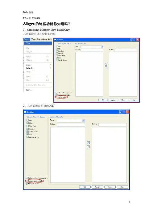
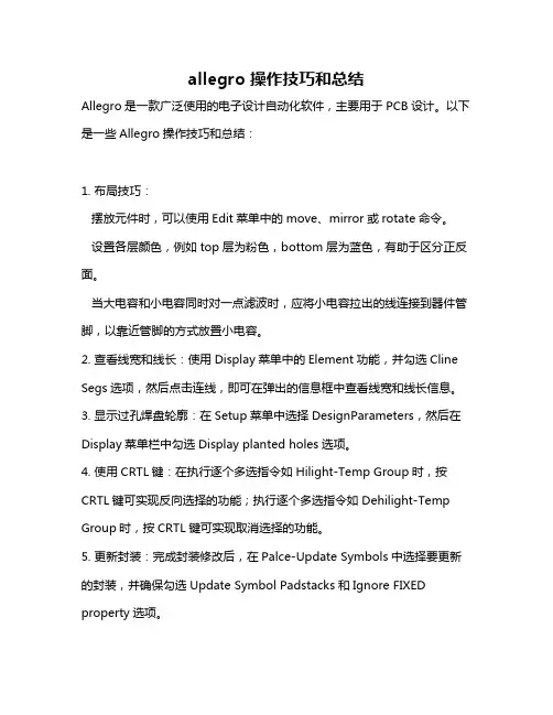
Allegro的这些功能你知道吗?1、Constraints Manager-View Failed Only 只查看没有通过检查的约束2、只查看绑定约束的NET3、一般当我们将PCB保存为新的文件名的时候,Allegro默认打开的就是新文件。
如何存为新文件的同时,打开的文件还是不变?在控制台命令栏输入“write”4、如何移动Drill Chart的位置?生成过一次Drill Legend,Allegro会记住Drill Chart的位置,如果这个位置放错了,怎么去改变呢?Move--Group5、NC Drill Legend固定行高Drill--Customization,Symbol SizeX&Y列填写固定值6、显示属性当你给某些elements加上属性,想再去看看具有这样属性的elements在PCB上的分布的时候Menu--Display/Property/Graphics tab7、当光标停在某个elements上的时候显示其信息(有点像Allegro16.X)Menu-Setup>User Preferences>Z-Early-Adopter>datatips注意Show Element>Find tab有没有勾选8、Z-copy到多层使用通配符“*”(例如:GND*,假设有很多层以GND开头命名)9、焊盘叠加产生的DRC有时候会有共焊盘的需求,这样的产生的DRC怎样消除?设置一个symbol的PACKAGE_HEIGHT_MAX小于另一个symbol的PACKAGE_HEIGHT_MIN即可10、在PCB中移动某一个PIN给symbol加上“Unfixed_Pins”属性11、Copy Shape到其他层12、这样的线每次还要修是不是很麻烦?设置下就可以,Setup>User Preference>Etch>padentry_factor效果:。

allegro 操作技巧和总结Allegro是一款广泛使用的电子设计自动化软件,主要用于PCB设计。
以下是一些Allegro操作技巧和总结:1. 布局技巧:摆放元件时,可以使用Edit菜单中的move、mirror或rotate命令。
设置各层颜色,例如top层为粉色,bottom层为蓝色,有助于区分正反面。
当大电容和小电容同时对一点滤波时,应将小电容拉出的线连接到器件管脚,以靠近管脚的方式放置小电容。
2. 查看线宽和线长:使用Display菜单中的Element功能,并勾选Cline Segs选项,然后点击连线,即可在弹出的信息框中查看线宽和线长信息。
3. 显示过孔焊盘轮廓:在Setup菜单中选择DesignParameters,然后在Display菜单栏中勾选Display planted holes选项。
4. 使用CRTL键:在执行逐个多选指令如Hilight-Temp Group时,按CRTL键可实现反向选择的功能;执行逐个多选指令如Dehilight-Temp Group时,按CRTL键可实现取消选择的功能。
5. 更新封装:完成封装修改后,在Palce-Update Symbols中选择要更新的封装,并确保勾选Update Symbol Padstacks和Ignore FIXED property选项。
6. 设置约束规则:在Setup-Constrains-Set Standard Values中设置线宽和线间距,间距主要包括pin to pin、line to pin、line to line等。
主要使用spacing rule set和physical rule set。
7. 设置Hilight的显示方式:在Setup-User Preferences-Display中勾选Display_Nohilitefont,则以实线显示Hilight,反之则以虚线显示。
8. 设置Differential Pair属性:先设定对net的Differential Pair property,然后在Constraints System控制面板中选择Spacing Rule Nets栏的Attach Property Nets,并在Allegro窗口Control Panel的Find by Name下选择Property,选取相应Property,再对其套用Spacing Rule即可。
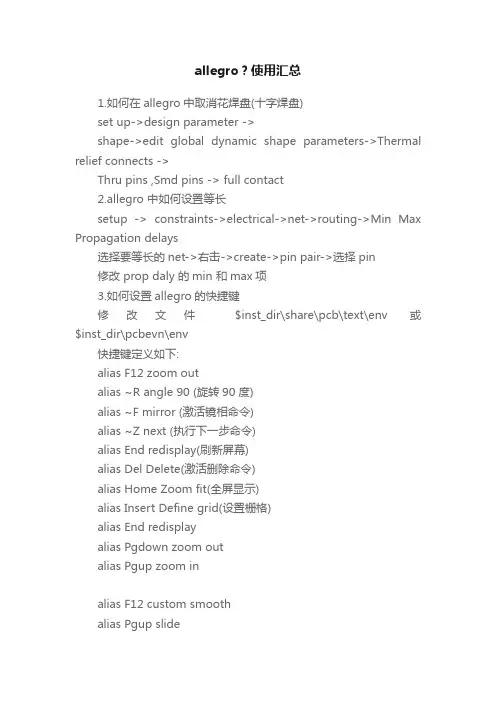
allegro?使用汇总1.如何在allegro中取消花焊盘(十字焊盘)set up->design parameter ->shape->edit global dynamic shape parameters->Thermal relief connects ->Thru pins ,Smd pins -> full contact2.allegro 中如何设置等长setup -> constraints->electrical->net->routing->Min Max Propagation delays选择要等长的net->右击->create->pin pair->选择pin修改 prop daly 的min 和max项3.如何设置allegro的快捷键修改文件$inst_dir\share\pcb\text\env 或$inst_dir\pcbevn\env快捷键定义如下:alias F12 zoom outalias ~R angle 90 (旋转90 度)alias ~F mirror (激活镜相命令)alias ~Z next (执行下一步命令)alias End redisplay(刷新屏幕)alias Del Delete(激活删除命令)alias Home Zoom fit(全屏显示)alias Insert Define grid(设置栅格)alias End redisplayalias Pgdown zoom outalias Pgup zoom inalias F12 custom smoothalias Pgup slidealias Pgdown donealias Home hilightalias End dehilightalias Insert add connectalias Del Delete4.如何在allegro中删除有过孔或布线的层时不影响其他层1.输出specctra的dsn文件allegro->file->export->router->demo.dsn->run2.产生session文件specctra(pcb router)->file->write->session->demo.ses->ok3.删除某一层中的布线和过孔delete(ctrl+D)->..4.删除allegro中的板层setup->cross section->鼠标右键->delete5.导入session文件allegro->file->import->router->demo.ses->run也可先将通过该层的过孔先替换成顶层焊盘,删除该层以后再替换回来5.如何在Allegro中同时旋转多个零件1.Edit->Move 在Options中Rotation的Point选User Pick2 再右键选Term Group 按住鼠标左键不放并拉一个框选中器件多余的可用Ctrl+鼠标左键点击去掉.3. 选好需整体旋转的器件后右键complete.4. 提示你Pick orgion 鼠标左键选旋转中心.5 下面右键选rotate 即可旋转了.6.allegro 16.0 透明度设置display->colour/visibility->display->OpenGL->Global transparency->transparent7.allegro Drill hole size is equal or larger than smallest padsize.Pad will be drilled away.提示Drill hole size is equal or larger than smallest pad size.Pad will be drilled away.不用理睬这一提示8.ALLEGRO 如何生成钻孔文件Manufacture -> NC -> Drill Customization->auto generate symbolsManufacture -> NC -> Drill LegendManufacture -> NC ->NC parameters->enhanced excellon format->closeManufacture -> NC -> NC Drill->auto tool select->optimize drill head travel9.CAM350如何正确导入钻带文件导进去后MACRO->PLAY->选择(CAM350--SCRIPTS)PADS_DRILL->选择钻带的REP文件还没测试过,rep文件从哪儿来的呢10.allegro 如何设置route keepin,package keepin1.setup->area->route keepin,package keepin ->画框2.edit ->z-copy->options->package keepin,route keepin->offset->50->点击外框11.allegro 中如何禁止显示shape完全禁止的方法没找到setup->user preference editor->display->display_shapefill->输入一个较大的数shape在显示时就不是那么显眼了set-user preference editor-shape-no shape fill(v)12.如何在allegro设置自定义元件库路径在下面两个位置添加自定义元件的路径Setup->User Preferences Editor->Design_paths->padpath Setup->User Preferences Editor->Design_paths->psmpath1.在allegro中如何修改线宽在Allegro的Setup->constraints里的set standard values中可定义每一层走线的宽度,比如,可以定义VCC和GND的线宽为10 Mil。
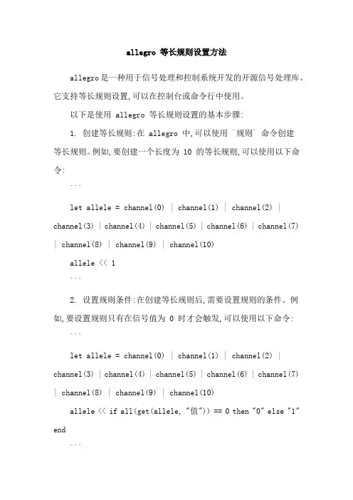
allegro 等长规则设置方法allegro是一种用于信号处理和控制系统开发的开源信号处理库。
它支持等长规则设置,可以在控制台或命令行中使用。
以下是使用 allegro 等长规则设置的基本步骤:1. 创建等长规则:在 allegro 中,可以使用 `规则` 命令创建等长规则。
例如,要创建一个长度为 10 的等长规则,可以使用以下命令:```let allele = channel(0) | channel(1) | channel(2) | channel(3) | channel(4) | channel(5) | channel(6) | channel(7) | channel(8) | channel(9) | channel(10)allele << 1```2. 设置规则条件:在创建等长规则后,需要设置规则的条件。
例如,要设置规则只有在信号值为 0 时才会触发,可以使用以下命令:```let allele = channel(0) | channel(1) | channel(2) | channel(3) | channel(4) | channel(5) | channel(6) | channel(7) | channel(8) | channel(9) | channel(10)allele << if all(get(allele, "值")) == 0 then "0" else "1" end```这里使用了 `get(allele, "值")` 来获取信号值,如果信号值为 0,则返回 0,否则返回 1。
`all(get(allele, "值", 0))` 表示计算所有信号值之和,如果结果为 0,则返回 0,否则返回 1。
3. 运行规则:等长规则准备好后,可以使用 `send(allele)` 命令将规则触发。
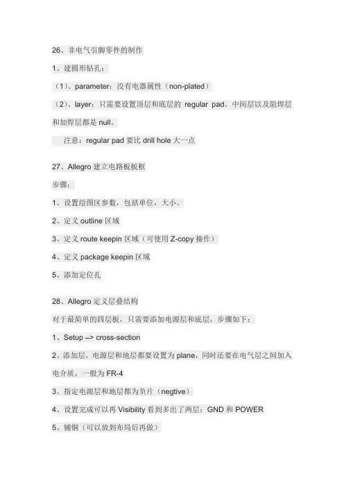
26、非电气引脚零件的制作1、建圆形钻孔:(1)、parameter:没有电器属性(non-plated)(2)、layer:只需要设置顶层和底层的regular pad,中间层以及阻焊层和加焊层都是null。
注意:regular pad要比drill hole大一点27、Allegro建立电路板板框步骤:1、设置绘图区参数,包括单位,大小。
2、定义outline区域3、定义route keepin区域(可使用Z-copy操作)4、定义package keepin区域5、添加定位孔28、Allegro定义层叠结构对于最简单的四层板,只需要添加电源层和底层,步骤如下:1、Setup –> cross-section2、添加层,电源层和地层都要设置为plane,同时还要在电气层之间加入电介质,一般为FR-43、指定电源层和地层都为负片(negtive)4、设置完成可以再Visibility看到多出了两层:GND和POWER5、铺铜(可以放到布局后再做)6、z-copy –> find面板选shape(因为铺铜是shape)–> option面板的copy to class/subclass选择ETCH/GND(注意选择create dynamic shape)完成GND层覆铜7、相同的方法完成POWER层覆铜Allegro生成网表1、重新生成索引编号:tools –> annotate2、DRC检查:tools –> Design Rules Check,查看session log。
3、生成网表:tools –> create netlist,产生的网表会保存到allegro文件夹,可以看一下session log内容。
29、Allegro导入网表1、file –> import –> logic –> design entry CIS(这里有一些选项可以设置导入网表对当前设计的影响)2、选择网表路径,在allegro文件夹。
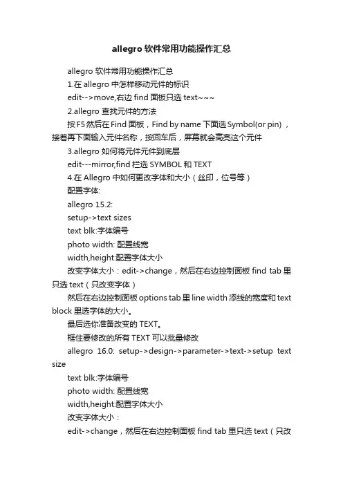
allegro软件常用功能操作汇总allegro 软件常用功能操作汇总1.在allegro中怎样移动元件的标识edit-->move,右边find面板只选text~~~2.allegro 查找元件的方法按F5然后在Find 面板,Find by name 下面选Symbol(or pin) ,接着再下面输入元件名称,按回车后,屏幕就会高亮这个元件3.allegro 如何将元件元件到底层edit---mirror,find栏选SYMBOL和TEXT4.在Allegro中如何更改字体和大小(丝印,位号等)配置字体:allegro 15.2:setup->text sizestext blk:字体编号photo width: 配置线宽width,height:配置字体大小改变字体大小:edit->change,然后在右边控制面板find tab里只选text(只改变字体)然后在右边控制面板options tab里line width添线的宽度和text block里选字体的大小。
最后选你准备改变的TEXT。
框住要修改的所有TEXT可以批量修改allegro 16.0: setup->design->parameter->text->setup text sizetext blk:字体编号photo width: 配置线宽width,height:配置字体大小改变字体大小:edit->change,然后在右边控制面板find tab里只选text(只改变字体)然后在右边控制面板options tab里line width添线的宽度和text block里选字体的大小。
class->ref des->new sub class->silkscreen_top最后选你准备改变的TEXT,框住要修改的所有TEXT可以批量修改, 注意:如果修改顶层丝印要先关掉底部丝印层,silkscreen_bottom和display_bottom--------------------------------------------------------------------在建封装的时候可以设定5.如何allegro在中取消Package to Package Spacing的DRC 检测setup -> constraint -> design constraints -> package to package ->off6.fanout by pick 的用途route->fanout by pick给bga自动的打via,对某个器件进行fanout,通俗的说就是从pin拉出一小段表层或底层线,打个孔7.No Placement Grid was found 的处理方法edit -> z-copy -> option->package keepin层-> offset =40 或者Setup -> Area -> Package KeepinROUTING KEEPIN 一般内移40MIL,PACK AGE KEEPING 一般内移120MIL8.在PCB Editor 启动Specctra的方法点击菜单route ->route Editor 启动9.ERROR Unable to open property mapping file: devparam.txt.ERROR Unable to open property mapping file: devparam.txt.解决方法PSpice->Edit Simulation Profile-> Configuration Files->Library-> Library path->(toolspspicelibrary)资讯版权声明:本网转载自其它媒体的信息,转载目的在于传递更多信息,并不代表本网赞同其观点和对其真实性负责,如有版权问题,可以立即删。
Allegro PCB几种简捷命令设置方法1. 概述Allegro PCB是一种电子设计自动化(EDA)工具,用于设计和布局印制电路板(PCB)。
在使用Allegro PCB进行设计时,掌握一些简捷命令设置方法可以提高工作效率和便捷性。
本文将介绍几种常用的简捷命令设置方法,帮助用户更好地使用Allegro PCB。
2. 快捷键设置Allegro PCB支持用户自定义快捷键,通过设置适合自己习惯的快捷键,可以快速调用常用命令,提高工作效率。
以下是设置快捷键的步骤:1.打开Allegro PCB软件,在菜单栏选择”Options” -> “UserPreferences”。
2.在弹出的”User Preferences”对话框中,选择”Hotkeys”选项卡。
3.在快捷键列表中选择需要设置的命令,点击”Add”按钮。
4.在弹出的”Hotkey Assignment”对话框中,按下要设置的快捷键,点击”OK”按钮。
5.重复上述步骤,为其他命令设置快捷键。
6.设置完成后,点击”OK”按钮保存设置。
通过设置自定义快捷键,用户可以根据自己的需求,将常用的命令设置为方便的快捷键,提高操作效率。
3. 命令别名设置除了设置快捷键外,Allegro PCB还支持为命令设置别名。
通过设置命令别名,用户可以使用简短的命令来调用复杂的操作,提高工作效率。
以下是设置命令别名的步骤:1.打开Allegro PCB软件,在菜单栏选择”Options” -> “UserPreferences”。
2.在弹出的”User Preferences”对话框中,选择”Command Aliases”选项卡。
3.在命令别名列表中选择需要设置的命令,点击”Add”按钮。
4.在弹出的”Command Alias”对话框中,输入命令别名,点击”OK”按钮。
5.重复上述步骤,为其他命令设置别名。
6.设置完成后,点击”OK”按钮保存设置。

allegro使用技巧1. 鼠标设定: 在ALLEGRO视窗 LAYOUT时,每执行一个指令例:Add connect, Show element等鼠标会跳到Option窗口,这样对layout造成不便.1) 控制面版>滑鼠之移动选项中,指到预设按钮(或智慧型移动):取消“在对话方块将滑鼠指标移到预设按钮”设置2. Text path设置: 在ALLEGRO视窗 LAYOUT时,不能执行一些指令:Show element, Tools>report…1) 应急办法:蒐寻一个相应的log文档copy到档案同一路径即可.2) Setup>User Preference之Design_Paths>textpath项设為:C:\cadance\PSD_14.1\share\pcb/text/views即可.3. 不能编辑Net Logic.1) Setup>User Perference之项选择logic_edit_enabled,点选為允许编辑Net Logic, 默认為不能编辑Net Logic.4. 转gerber前需update DRC,应尽量将DRC排除,有些可忽略的DRC如何消除?1) logo中文字所產生的K/L error,可另外增加一个subclass,这样该文字不用写在ETCH层,可消除K/L error.2) 有些可忽略的P/P,P/L 的error,可给那些pin增加一个property---NO_DRC, 操作:Edit/Properties,选择需要的pin,选NO_DRC, Apply, OK5. 对某些PIN添加了”NO DRC”的属性可ERRO并不能消除﹐这是為什么?1) “NO DRC”属性只争对不同的网络﹐对相同的网络要清除ERRO,可设定Same net DRC 為off.6. 如何Add new subclass:1) Setup>Subclass之Define Subclass窗口选Class,点add”New subclass” 通常用到的new subclass有:Geometry\Board Geometry\之Top_notes, Bottom_notes, Gnd_notes, Vcc_notes等。
Allegro 中如常用命令Allegro 中如何使用半径添加圆弧窗口的下面命令信息部分,你将看到如下的提示:Pick arc CENTER point…[pic]??在屏幕上适当的位置上点击鼠标左键,设置圆弧的中心点,这时,你可以看到Allegro窗口的下面命令信息部分得到如下的提示:Pick arc START point…[pic]??向右移动光标,在适当的位置上点击鼠标左键,设置圆弧半径及圆弧的起始点,在Allegro 窗口的下面命令信息部分,你将看到如下的提示:Pick arc END point…[pic]??移动光标,在适当的位置上点击鼠标左键,设置圆弧的结束点。
点击鼠标右键,选择?? Done命令,或者按F2 键,完成圆弧的绘制。
[pic]??注意:在执行?? Add—Arc?? w/Radius?? 命令后,注意Allegro控制面板中各项内容的设置。
你需要为你绘制的圆弧设置适当的类(Class)和子类(Subclass)、线宽(Line width)、最小增加角度(Lock angle)和线的类型(Linefont)。
[pic]??也就是说,执行Add—Arc w/Radius 命令进行可以完成圆弧形状的绘制,而绘制圆弧的属性,则需要在控制面板的Options表格中设置和定义。
allegro怎么样复制板框到另外一块中file/export/sub-drawing然后选中板框,导出。
把导出的文件与目标板放在同一目录下。
在目标板板上运行file/import/sub-drawing,选中刚导出的文件,导入即可。
Allegro:如何把元件放到电路板底层选中元件右击/edit/菜单下面mirrorAllegro:如何旋转元件选中右键选择rotato如题,例如带有弧形的边框?allegro中如何画不规则板框1、菜单add ->line>option选BOARD GEOMETRY>LINE LOCK选ARC就可以画出圆弧形的边框了!2、setup>area>route keepin 直接画线就可以,封闭区域里面就是route keepin区域!allegro中更换元件封装allegro自带一个更新功能,它在place菜单下有一个Update Symbols菜单,点击它这里可以在package symbols目录下列出了你制作的个人封装,找到你已经修改的封装元件打上勾,然后点击Refresh按钮就可以更换封装了。
产品研发流程在看电路板的设计流程之前,可以先了解电路板的设计在整个产品的研发(R&D)环节中所占位置,如下图所示。
鼠标操作请激活Allegro,然后再使用其左上角的“File/Open…” 命令,叫出电路板档案demo_route.brd ( 位于C:\project\allegro 目录),接下来说明鼠标的操作使用,在Allegro 系统中,其鼠标三个按键之功能如下:1. 鼠标左键–选取功能(1) 用来在菜单内选择命令,并执行之。
(2) 用来选取欲动作的对象。
2. 鼠标中键–画面控制功能(1) 按住鼠标中键不放开,并同时移动鼠标,可以平移目前的可视画面位置。
(2) 按一下鼠标中键,可以控制屏幕的大小,至于是做放大或缩小的功能,则需视上一次是做放大或缩小的功能而定,即与上一次做相同的功能。
3. 鼠标右键–弹出式选单当有使用命令时,可在Design Window 中下按一下鼠标右键,会拉出目前命令的弹出式菜单,而每一个命令的弹出式选单,可能会有不一样的选项,以下介绍各个选项:例如:点MOVE命令,再点鼠标右键其下拉菜单的子项分析如下:(1) Done:执行本命令后,才结束本命令。
(2) Oops :复原上一次的动作 ( Undo 功能 )。
(3) Cancel:取消本命令的执行。
(4) Temp Group :开始进行“自由多点选取” 的动作(5) Complete:结束“自由多点选取” 的动作。
(6) Cut:选两点以截切出一个线段。
(7) Reject:在相同位置选取另一个合乎Find 的对象。
(8) AltSymbol:选取另一个可用的零件包装(Foot Print)。
(9) Mirror Geometry:将选取的对象进行换Mirror 的动作。
(10)Align:将对象的角度调成一致。
(11) Rotate :将对象进行旋转的动作。
同时按下键盘的 CTRL 键及鼠标右键,然后移动鼠标,可在画面上直接写出Stroke 的样式,若符合Stroke 所定义的样式,系统则立即执行 Stroke 功能,以下为系统内定的 Stroke 样式及所代表的命令:Stroke 样式命令W World ViewZ Zoom InM MoveC Copy^ DeleteU Oops控制面板1. 选项项目(Options) 用来显示正在使用中命令的细部选项,以使用move 命令为例。
ALLEGRO使用教程一. PCB窗口介面介绍运行PCB EDIT 出现对话框注:不同的选项能实现的功能有所不同,一般P C B画板时选择A l l e g r o E x p e r t1.P C B介面2.工具栏其中工具栏的图标在相应的菜单栏中都可以找到,其对应关系如下:红色的文字对应菜单栏的选项。
如果工具栏图标太多或者太少,可以通过菜单View=>Customization=>Toolbar 自己增加或者减少一些不常用的图标3.控制栏说明控制栏主要有三大选择项:Option、Find 和Visibility通过控制面板的Option 标签可选择被激活的类或子类,在Allegro 数据库中,所有元素都有一个类属性(CLASS)或子类属性(SUBCLASS)。
通过控制面板的Find 标签,可以选择各种元素,如Nets、Lines、Vias等,当执行各种命令时,都需要在Find 标签中选择好相应的元素。
以移动命令为例,说明一下“Find”选项含义。
选择菜单Edit=>Move,再看“Find”选项如图所示,其中有多个复选框可供选择,想移动什么东西,一定要将其对应的复选框钩上“√”,比如,如果想要移动元件,首先点击一下“All Off”按钮,关闭所有的复选框,然后再将复选框“Symbols”钩上“√”,就可以对元件进行移动了。
如果要查看某个元件的信息,可以通过Display->Element,或单击图标,然后在Find 标签中选择好相应的元素。
通过控制面板的Visibility 标签,可以选择Etch 、Pin、Via、DRC 的各个子类的可视性。
“Visibility”下的“Views”可以用于快速切换窗口显示,其中的列表项内容是在进行过光绘的输出设置之后,就可以显示出来。
“Visibility”下的“layer”的意思就是对各层进行打开或者关闭显示,将小方框里打上“√”表示打开这层的显示,取消“√”表示不显示该层。
20条Allegro操作指令1.鼠标设定:在Allegro视窗layout时,每执行一个指令例:Addconnect, Show element等鼠标会跳到Option窗口,这样对layout 造成不便.1)控制面版>滑鼠之移动选项中,指到预设按钮(或智慧型移动):取消“在对话方块将滑鼠指标移到预设按钮”设置2.Text path设置:在ALLEGRO视窗LAYOUT时,不能执行一些指令:Showelement, Tools>report1)应急办法:寻一个相应的log文档copy到档案同一路径即可2)Setup>UserPreference之Design_Paths>textpath项设为:C:cadancePSD_14.1sharePCB/text/views即可3.转gerber前需updateDRC,应尽量将DRC排除,有些可忽略的DRC 如何消除?1)logo中文字所產生的K/Lerror,可另外增加一个subclass,这样该文字不用写在ETCH层,可消除K/Lerror.2)有些可忽略的P/P,P/L的error,可给那些pin增加一个property—NO_DRC,操作:Edit/Properties,选择需要的pin,选NO_DRC,Apply, OK4.对某些PIN添加了”NODRC”的属性可ERRO并不能消除﹐这是為什么?1)“NO DRC”属性只争对不同的网络﹐对相同的网络要清除ERRO,可设定Samenet DRC为off5.对differentialpair nets 之”netspace type” properties应怎样设定?1)先设定对net设定一differentialpair property,2)再在constraintssystem 控制面板中选择spacingrule nets 栏的attachproperty nets,并在allegro窗口controlpanel的findby name 下选择property3)选取相应property4)再对其套用spacingrule 即可6.怎样更新Allegro layout窗口下的toolbar和displayoption设定1)View>customization>tool bar中,勾上欲显示在窗口中的内容;欲锁住右边displayoption窗口,在view>customization>displayoption中选locked_right.这样重开一个ALLEGRO窗口时就会恢复上一次的设定7.Color and Visibility 视窗过长,有的人在使用一阵子后会发现Colorand Visibility 视窗过长不好关掉其视窗,这时有两个方法可解决1)关掉Allegro程式然后删掉pcbenv路径下的allegro.geo,再进Allegro就会重设其视窗2)将Allegro.geo档中的Form.cvf_main改其值6040 0 4308.开啟allegro时,会自动在桌面上生成allegro.jrl档,怎麼解决?可能的情况:环境变数中将temp路径设成了桌面1)环境变数中将temp应设成:%USERPROFILE%LocalSettingsTemp2)Setup>User Perference之Design_Paths>textpath项设成了桌面9.我们在走线时﹐经常碰到这样的问题﹒走线时候我们渴望RATS显示随著走线而改变﹐以便走线﹒Setup/Drawingoptions之Display中的RatsnestPoints有两选项﹕1)Pin to Pin (Rats在Pin之间显现)2)Closest end point (Rats随走线改变显示)10.怎样复制多个有规律的VIA1)点COPY在右命令栏X,Y中输入VIA的个数,则间距以PIN舆PIN之间距為准11.有时打开allegro窗口,menu会反白无效1)将不是系统路径(c:cadencepsd_14.1sharepcbextcuimenus)下的men 文档删除,再更新系统路径下的men文档,2)再重新开一个allegro窗口12.Menu之Path设置1)Setup>User Preferences之Ui_paths选menupath项,其默认Path 为当前路径和C:CadencePSD_14.1SharePcbTextcuimenus,当你要改变Menu时,建议新增一个Menu路径以防损坏系统的Menu 13.env中快捷键的保留1)将C:Pcbenv下的env档中alias项Copyto:C:CadencePSD_14.1SharePcbText下的env档中。
allegro控制台命令控制台命令File (1)Edit (4)View (6)Add (7)Display (8)Setup (9)Layout (11)V oid (12)Shape (12)Logic (13)Place (14)Route (16)Analyze (17)Manufacture (19)Tools (21)Help (22)如何设置allegro的快捷键 (23)FileFile-NewnewFile-OpenopenFile-SavesaveFile-Save Assave_asFile-Create Symbolcreate symbol (in Symbol Editor only)File-Import-Logicnetin paramFile-Import-Artwork load photoplotFile-Import-Streamload streamFile-Import-IPFload plotFile-Import-DXFdxf inFile-Import-IDFidf inFile-Import- IFFiff inFile-Import-SPECCTRA specctra inFile-Import-Redac redac inFile-Import-Visula visula inFile-Import-PADSpads inFile-Import-PCADpcad inFile-Import-Sub-Drawing clppasteFile-Import-Techfile techfile inFile-Import-Active Times signal atimesFile-Import-Placementplctxt inFile-Annotationsannotation inFile-Export-LogicfeedbackFile-Export-Netlist w/Properties netoutFile-Export-IPFcreate plotFile-Export-DXFdxf outFile-Export-IDFidf outFile-Export-SPECCTRA specctra_outFile-Export-Sub-Drawing clpcopyFile-Export-LibrariesdlibFile-Export-Techfiletechfile outFile-Export-Placementplctxt outFile-Export-Annotations annotation outFile-Export-IPC 356ipc356 outFile-Export-Valor ODB ++ inside odb_outFile-Export-Save design to 14.0 downrevFile-ViewlogviewlogFile-File ViewerNo corresponding commandFile-Plot Setupplot setupFile-Plot Preview (Windows NT only) plot previewFile-PlotplotFile-Propertiesfile_propertyFile-Change EditortoolswapFile-ScriptscriptFile-ExitexitEditEdit-MovemoveEdit-CopycopyEdit-MirrormirrorEdit-SpinspinEdit-ChangechangeEdit-DeletedeleteEdit-Shapeshape editEdit-Z-Copyzcopy shapeEdit-Delete Unconnected Shapes delete unconnectedEdit-Split Plane-Parameters split plane paramsEdit-Split Plane-Createsplit plane createEdit-Split Plane-Locate Islands locate islandsEdit-Compose Shape compose shapeEdit-Decompose Shape decompose shapeEdit-VertexvertexEdit-Delete Vertexdelete vertexEdit-Boundary (Shape editor only) boundaryEdit-Change Net (Pick) (Shape editor only) changenet pickEdit-Change Net (Name) (Shape editor only) changenet nameEdit-Texttext editEdit-Chamfer (in Designer and Studio series) draft chamferEdit-Fillet (in Designer and Studio series) draft filletEdit-GroupsgroupeditEdit-Propertiesproperty editViewView-Zoom By Pointszoom pointsView-Zoom Fitzoom fitView-Zoom Inzoom inView-Zoom Outzoom outView-Zoom Worldzoom centerView-Zoom Centerzoom centerView-Zoom Previouszoom previousView-Color View Save colorview createView-Color View Restore Last colorview restoreView-RefreshNo corresponding commandView-Customization-Display display paramView-Customization-Toolbar No corresponding commandAddAdd-Lineadd lineAdd-Arc w/Radiusadd rarcAdd-3pt Arcadd arcAdd-Circleadd circleAdd-Rectangleadd rectAdd-Frectangleadd frectAdd-Textadd textAdd-Shapes-Solid Filladd fshapeAdd-Shapes-Unfilledadd ufshapeAdd-Shapes-Cross Hatch Fill add xshapeDisplayDisplay-Color/Visibility colorDisplay-Color Prioritycolor priorityDisplay-Elementshow elementDisplay-Measureshow measureDisplay-Parasiticshow parasiticDisplay-Propertyshow propertyDisplay-HighlighthilightDisplay-DehighlightdehilightDisplay-Show Rats-Allrats allDisplay-Show Rats-Components rats componentDisplay-Show Rats-Netrats netDisplay-Blank Rats-Allunrats allDisplay-Blank Rats-Components unrats componentDisplay-Blank Rats-Nets unrats netSetupSetup-Drawing Sizedrawing paramSetup-Drawing OptionsstatusSetup-Text Sizesdefine textSetup-Gridsdefine gridSetup-Subclassesdefine subclassSetup-Cross-sectiondefine xsectionSetup-Vias-Define B/B Viadefine bbviaSetup-Vias-Auto Define B/B Viaauto define bbviaSetup-ConstraintscnsSetup-Electrical Constraint Spreadsheet cmgrSetup-Property Definitionsdefine propertySetup-Define Listsdefine listSetup-Areas-Package Keepinkeepin packageSetup-Areas-Package Keepout keepout packageSetup-Areas-Package Height package_heightSetup-Areas-Route Keepinkeepin routerSetup-Areas-Route Keepoutkeepout routerSetup-Areas-Via KeepoutSetup-Areas-Probe Keepoutkeepout probeSetup-Areas-Gloss Keepoutkeepout glossSetup-Areas-Photoplot Outlinekeepin photoSetup-User Preferencesenv editorLayoutLayout menu selections are available only in the Symbol EditorLayout-Pinsadd pinLayout-Connectionsadd connectLayout-SlideslideLayout-Labels-RefDeslabel refdesLayout-Labels-Devicelabel deviceLayout-Labels-Valuelabel valueLayout-Labels-ToleranceLayout-Labels-Part Numberlabel partVoidV oid menu selections are available only in the Shape EditorV oid-Shapevoid shapeV oid-Circlevoid circleV oid-Elementvoid elementV oid-Autovoid allShapeShape menu selections are available only in the Shape EditorShape-Parametersshape paramShape-Checkshape checkShape-Fillshape fillLogicLogic-Net Logicnet logicLogic-Net Schedulenet scheduleLogic-Assign Differential Pairdiff pairsLogic-Identify DC Netsidentify netsLogic-Assign RefDesassign refdesLogic-Auto Rename RefDes-Rename rename paramLogic-Auto Rename RefDes-Design rename area designLogic-Auto Rename RefDes-Room rename area roomLogic-Auto Rename RefDes-Window rename area windowLogic-Auto Rename RefDes-List rename area listLogic-Change PartsparteditLogic-Terminator Assignment ecl paramPlacePlace-Manuallyplace manualPlace-Quickplace quickplacePlace-SPECCTRAspecctraPlace-Autoplace-Insight place insightPlace-Autoplace-Parameters place paramPlace-Autoplace-Top Grids place set topgridPlace-Autoplace-Bottom Grids place set bottomgridPlace-Autoplace-Design place area designPlace-Autoplace-Roomplace area roomPlace-Autoplace-Window place area windowPlace-Autoplace-List place area listPlace-Interactiveplace interactivePlace-Swap-Pinsswap pinsPlace-Swap-Functions swap functionsPlace-Swap-Components swap componentsPlace-Autoswap-Parameters swap paramPlace-Autoswap-Design swap area designPlace-Autoswap-Room swap area roomPlace-Autoswap-Window swap area windowPlace-Autoswap-List swap area listPlace-Evaluate-Parameters eval paramPlace-Evaluate-Design eval area designPlace-Evaluate-Roomeval area roomPlace-Evaluate-Window eval area windowPlace-Evaluate-Listeval area listPlace-Update Symbolsrefresh symbolPlace-Replace SQ Temporary-Devices replace temp_devicePlace-Replace SQ Temporary-Symbols replace temp_symbolsRouteRoute-Connectadd connectRoute-SlideslideRoute-Custom Smoothcustom smoothRoute-SPECCTRA-Run Router Checks specctra checksRoute-SPECCTRA-Route by Pick route_by_pickRoute-SPECCTRA-Route Automatic auto_routeRoute-SPECCTRA-Interactive Editor specctraRoute-Gloss-Parametersgloss paramRoute-Gloss-Designgloss area designRoute-Gloss-Roomgloss area roomRoute-Gloss-Windowgloss area windowRoute-Gloss-HighlightNo corresponding commandRoute-Gloss-Listgloss area listRoute-Testprep-Auto testpreop paramRoute-Testprep-Create Probe probe createRoute-Testprep-Delete Probe probe deleteRoute-Testprep-Swap Probe probe swapRoute-Testprep-NC Tape Probes nctapeAnalyzeAnalyze-SI/EMI Sim-Initialize signal initAnalyze-SI/EMI Sim-Library signal libraryAnalyze-SI/EMI Sim-Modelsignal modelAnalyze-SI/EMI Sim-Model Dump/Refresh signal model refreshAnalyze-SI/EMI Sim-Preferencessignal prefsAnalyze-SI/EMI Sim-Audit-Design Auditsignal auditAnalyze-SI/EMI Sim-Audit-Net Auditsignal audit netAnalyze-SI/EMI Sim-Audit-Audit One Librarysignal lib auditAnalyze-SI/EMI Sim-Audit-Audit List of Librariessignal libs auditAnalyze-SI/EMI Sim-Probesignal probeAnalyze-SI/EMI Sim-Xtalk Tablesignal xtalktableAnalyze-EMI Rules-Initializesignal eminitAnalyze-EMI Rules-Auto Setupsignal emiautopropmainAnalyze-EMI Rules-Manual Setupsignal emimanualpropmainAnalyze-EMI Rules-Rule Selectsignal emiruleselectAnalyze-EMI Rules-Auditsignal emiverifyAnalyze-EMI Rules-Executesignal emiexecuteAnalyze-EMI Rules-Resultssignal emiresultsAnalyze-EMI Rules-Audit Reportsignal emiverifyreportAnalyze-EMI Rules-Execute Reportsignal emiexecutereportManufactureManufacture-Dimension/Draft commands in the Layout Editor are accessed under the Dimension menu item in the Symbol EditorManufacture-Dimension/Draft-Parametersdraft paramManufacture-Dimension/Draft-LineFontlinefontManufacture-Dimension/Draft-Linear Dimdimension linearManufacture-Dimension/Draft-Datum Dimdimension datumManufacture-Dimension/Draft-Angular Dimdimension angularManufacture-Dimension/Draft-Leader Linesleader onlyManufacture-Dimension/Draft-Diametral Leaderleader diametralManufacture-Dimension/Draft-Radial Leader leader radialManufacture-Dimension/Draft-Balloon Leaderleader balloonManufacture-Dimension/Draft-Chamfer Leaderleader chamferManufacture-Dimension/Draft-Chamfer draft chamferManufacture-Dimension/Draft-Filletdraft filletManufacture-Dimension/Draft-Create Detail create detailManufacture-Artworkfilm paramManufacture-Stream Outstream outManufacture-NC-Drill Parametersncdrill paramManufacture-NC-Drill Legendncdrill legendManufacture-NC-Drill Tapenctape_fullManufacture-NC-RoutencrouteManufacture-Cut Markscut marksManufacture-DFA CheckdfaManufacture-Create Couponscreate couponsManufacture-Silkscreensilkscreen paramManufacture-Variants-Create Assembly Drawing variant assemblyManufacture-Variants-Create Bill of Materials variant bomToolsTools-Create Modulecreate moduleTools-Padstack-Modify Design Padstack padeditdbTools-Padstack-Modify Library Padstack padeditlibTools-Padstack-Replacereplace padstackTools-Padstack-Group EditmultpadeditTools-Padstack-Refreshrefresh padstackTools-Pad-Boundaryeditpad boundaryTools-Pad-Restoreeditpad restoreTools-Pad-Restore ALL editpad restore allTools-Silkscreensilkscreen paramTools-Derive Connectivity derive connectivityTools-ReportsreportsTools-Technology File Compare techfile compareTools-Setup Advisorsetup advisorTools-Database Check dbcheckTools-Update DRCdrc updateHelpHelp-Allegro HelphelpHelp-Product NotesNo corresponding commandHelp-Known Problems and SolutionsNo corresponding commandHelp-Web Resources-SourcelinkNo corresponding commandHelp-Web Resources-EducationNo corresponding commandHelp-Web No corresponding commandHelp-ManualscdsdocHelp-Design FlowNo corresponding commandHelp-About AllegroNo corresponding command如何设置allegro的快捷键2010-01-24 00:21如何设置allegro的快捷键(ZT)修改变量文件,设置自定义快捷键。
菜单选项控制台命令FileFile-NewnewFile-OpenopenFile-SavesaveFile-Save Assave_asFile-Create Symbolcreate symbol (in Symbol Editor only)File-Import-Logicnetin paramFile-Import-Artworkload photoplotFile-Import-Streamload streamFile-Import-IPFload plotFile-Import-DXFdxf inFile-Import-IDFidf inFile-Import- IFFiff inFile-Import-SPECCTRA specctra inFile-Import-Redacredac inFile-Import-Visulavisula inFile-Import-PADSpads inFile-Import-PCADpcad inFile-Import-Sub-Drawing clppasteFile-Import-Techfiletechfile inFile-Import-Active Times signal atimesFile-Import-Placementplctxt inFile-Annotationsannotation inFile-Export-LogicfeedbackFile-Export-Netlist w/Properties netoutFile-Export-IPFcreate plotFile-Export-DXFdxf outFile-Export-IDFidf outFile-Export-SPECCTRAspecctra_outFile-Export-Sub-DrawingclpcopyFile-Export-LibrariesdlibFile-Export-Techfiletechfile outFile-Export-Placementplctxt outFile-Export-Annotations annotation outFile-Export-IPC 356ipc356 outFile-Export-Valor ODB ++ inside odb_outFile-Export-Save design to 14.0 downrevFile-ViewlogviewlogFile-File ViewerNo corresponding commandFile-Plot Setupplot setupFile-Plot Preview (Windows NT only) plot previewFile-PlotplotFile-Propertiesfile_property File-Change EditortoolswapFile-ScriptscriptFile-ExitexitEditEdit-MovemoveEdit-CopycopyEdit-MirrormirrorEdit-SpinspinEdit-ChangechangeEdit-DeletedeleteEdit-Shapeshape editEdit-Z-Copyzcopy shapeEdit-Delete Unconnected Shapes delete unconnectedEdit-Split Plane-Parameterssplit plane params Edit-Split Plane-Createsplit plane createEdit-Split Plane-Locate Islandslocate islandsEdit-Compose Shapecompose shapeEdit-Decompose Shapedecompose shapeEdit-VertexvertexEdit-Delete Vertexdelete vertexEdit-Boundary (Shape editor only) boundaryEdit-Change Net (Pick) (Shape editor only) changenet pickEdit-Change Net (Name) (Shape editor only) changenet nameEdit-Texttext editEdit-Chamfer (in Designer and Studio series) draft chamferEdit-Fillet (in Designer and Studio series) draft filletEdit-GroupsgroupeditEdit-Propertiesproperty edit ViewView-Zoom By Pointszoom pointsView-Zoom Fitzoom fitView-Zoom Inzoom inView-Zoom Outzoom outView-Zoom Worldzoom centerView-Zoom Centerzoom centerView-Zoom Previouszoom previousView-Color View Save colorview createView-Color View Restore Last colorview restoreView-RefreshNo corresponding commandView-Customization-Display display paramView-Customization-Toolbar No corresponding commandAddAdd-Lineadd lineAdd-Arc w/Radiusadd rarcAdd-3pt Arcadd arcAdd-Circleadd circleAdd-Rectangleadd rectAdd-Frectangleadd frectAdd-Textadd textAdd-Shapes-Solid Filladd fshapeAdd-Shapes-Unfilledadd ufshapeAdd-Shapes-Cross Hatch Fill add xshapeDisplayDisplay-Color/Visibility colorDisplay-Color Priority color priority Display-Elementshow elementDisplay-Measureshow measureDisplay-Parasiticshow parasiticDisplay-Propertyshow propertyDisplay-HighlighthilightDisplay-DehighlightdehilightDisplay-Show Rats-Allrats allDisplay-Show Rats-Components rats componentDisplay-Show Rats-Netrats netDisplay-Blank Rats-Allunrats allDisplay-Blank Rats-Components unrats componentDisplay-Blank Rats-Nets unrats netSetupSetup-Drawing Sizedrawing paramSetup-Drawing OptionsstatusSetup-Text Sizesdefine textSetup-Gridsdefine gridSetup-Subclassesdefine subclassSetup-Cross-sectiondefine xsectionSetup-Vias-Define B/B Viadefine bbviaSetup-Vias-Auto Define B/B Viaauto define bbviaSetup-ConstraintscnsSetup-Electrical Constraint Spreadsheet cmgrSetup-Property Definitionsdefine propertySetup-Define Listsdefine listSetup-Areas-Package Keepinkeepin packageSetup-Areas-Package Keepout keepout packageSetup-Areas-Package Height package_heightSetup-Areas-Route Keepin keepin routerSetup-Areas-Route Keepoutkeepout routerSetup-Areas-Via Keepoutkeepout viaSetup-Areas-Probe Keepoutkeepout probeSetup-Areas-Gloss Keepoutkeepout glossSetup-Areas-Photoplot Outlinekeepin photoSetup-User Preferencesenv editorLayoutLayout menu selections are available only in the Symbol EditorLayout-Pinsadd pinLayout-Connectionsadd connectLayout-SlideslideLayout-Labels-RefDeslabel refdesLayout-Labels-Devicelabel deviceLayout-Labels-Valuelabel valueLayout-Labels-Tolerancelabel toleranceLayout-Labels-Part Numberlabel partVoidVoid menu selections are available only in the Shape EditorVoid-Shapevoid shapeVoid-Circlevoid circleVoid-Elementvoid elementVoid-Autovoid allShapeShape menu selections are available only in the Shape EditorShape-Parametersshape paramShape-Checkshape check Shape-Fillshape fillLogicLogic-Net Logicnet logicLogic-Net Schedulenet scheduleLogic-Assign Differential Pairdiff pairsLogic-Identify DC Netsidentify netsLogic-Assign RefDesassign refdesLogic-Auto Rename RefDes-Rename rename paramLogic-Auto Rename RefDes-Design rename area designLogic-Auto Rename RefDes-Room rename area roomLogic-Auto Rename RefDes-Window rename area windowLogic-Auto Rename RefDes-List rename area listLogic-Change PartsparteditLogic-Terminator Assignmentecl paramPlacePlace-Manuallyplace manualPlace-Quickplace quickplacePlace-SPECCTRAspecctraPlace-Autoplace-Insight place insightPlace-Autoplace-Parameters place paramPlace-Autoplace-Top Grids place set topgridPlace-Autoplace-Bottom Grids place set bottomgridPlace-Autoplace-Design place area designPlace-Autoplace-Room place area roomPlace-Autoplace-Window place area windowPlace-Autoplace-Listplace area listPlace-Interactiveplace interactive Place-Swap-Pinsswap pinsPlace-Swap-Functionsswap functionsPlace-Swap-Componentsswap componentsPlace-Autoswap-Parametersswap paramPlace-Autoswap-Designswap area designPlace-Autoswap-Roomswap area roomPlace-Autoswap-Windowswap area windowPlace-Autoswap-Listswap area listPlace-Evaluate-Parameterseval paramPlace-Evaluate-Designeval area designPlace-Evaluate-Roomeval area roomPlace-Evaluate-Windoweval area windowPlace-Evaluate-Listeval area listPlace-Update Symbolsrefresh symbolPlace-Replace SQ Temporary-Devices replace temp_devicePlace-Replace SQ Temporary-Symbols replace temp_symbolsRouteRoute-Connectadd connectRoute-SlideslideRoute-Custom Smoothcustom smoothRoute-SPECCTRA-Run Router Checks specctra checksRoute-SPECCTRA-Route by Pick route_by_pickRoute-SPECCTRA-Route Automatic auto_routeRoute-SPECCTRA-Interactive Editor specctraRoute-Gloss-Parametersgloss paramRoute-Gloss-Designgloss area designRoute-Gloss-Roomgloss area roomRoute-Gloss-Windowgloss area windowRoute-Gloss-Highlight No corresponding commandRoute-Gloss-Listgloss area listRoute-Testprep-Autotestpreop paramRoute-Testprep-Create Probeprobe createRoute-Testprep-Delete Probeprobe deleteRoute-Testprep-Swap Probeprobe swapRoute-Testprep-NC Tape ProbesnctapeAnalyzeAnalyze-SI/EMI Sim-Initializesignal initAnalyze-SI/EMI Sim-Librarysignal libraryAnalyze-SI/EMI Sim-Modelsignal modelAnalyze-SI/EMI Sim-Model Dump/Refresh signal model refreshAnalyze-SI/EMI Sim-Preferencessignal prefsAnalyze-SI/EMI Sim-Audit-Design Auditsignal auditAnalyze-SI/EMI Sim-Audit-Net Auditsignal audit netAnalyze-SI/EMI Sim-Audit-Audit One Librarysignal lib auditAnalyze-SI/EMI Sim-Audit-Audit List of Librariessignal libs auditAnalyze-SI/EMI Sim-Probesignal probeAnalyze-SI/EMI Sim-Xtalk Table signal xtalktableAnalyze-EMI Rules-Initialize signal eminitAnalyze-EMI Rules-Auto Setup signal emiautopropmainAnalyze-EMI Rules-Manual Setup signal emimanualpropmainAnalyze-EMI Rules-Rule Select signal emiruleselectAnalyze-EMI Rules-Auditsignal emiverifyAnalyze-EMI Rules-Execute signal emiexecuteAnalyze-EMI Rules-Results signal emiresultsAnalyze-EMI Rules-Audit Report signal emiverifyreportAnalyze-EMI Rules-Execute Report signal emiexecutereportManufactureManufacture-Dimension/Draft commands in the Layout Editor areaccessed under the Dimension menu item in the Symbol EditorManufacture-Dimension/Draft-Parameters draft paramManufacture-Dimension/Draft-LineFont linefontManufacture-Dimension/Draft-Linear Dim dimension linearManufacture-Dimension/Draft-Datum Dim dimension datumManufacture-Dimension/Draft-Angular Dim dimension angularManufacture-Dimension/Draft-Leader Lines leader onlyManufacture-Dimension/Draft-Diametral Leaderleader diametralManufacture-Dimension/Draft-Radial Leader leader radialManufacture-Dimension/Draft-Balloon Leaderleader balloonManufacture-Dimension/Draft-Chamfer Leaderleader chamferManufacture-Dimension/Draft-Chamfer draft chamferManufacture-Dimension/Draft-Filletdraft filletManufacture-Dimension/Draft-Create Detail create detailManufacture-Artworkfilm paramManufacture-Stream Outstream outManufacture-NC-Drill Parametersncdrill paramManufacture-NC-Drill Legendncdrill legendManufacture-NC-Drill Tapenctape_fullManufacture-NC-RoutencrouteManufacture-Cut Markscut marksManufacture-DFA CheckdfaManufacture-Create Couponscreate couponsManufacture-Silkscreensilkscreen paramManufacture-Variants-Create Assembly Drawingvariant assembly Manufacture-Variants-Create Bill of Materials variant bomToolsTools-Create Modulecreate moduleTools-Padstack-Modify Design Padstack padeditdbTools-Padstack-Modify Library Padstack padeditlibTools-Padstack-Replacereplace padstackTools-Padstack-Group EditmultpadeditTools-Padstack-Refreshrefresh padstackTools-Pad-Boundaryeditpad boundaryTools-Pad-Restoreeditpad restoreTools-Pad-Restore ALLeditpad restore allTools-Silkscreensilkscreen paramTools-Derive Connectivityderive connectivityTools-ReportsreportsTools-Technology File Compare techfile compareTools-Setup Advisorsetup advisorTools-Database CheckdbcheckTools-Update DRCdrc updateHelpHelp-Allegro HelphelpHelp-Product NotesNo corresponding commandHelp-Known Problems and Solutions No corresponding commandHelp-Web Resources-SourcelinkNo corresponding commandHelp-Web Resources-EducationNo corresponding commandHelp-Web No corresponding commandHelp-ManualscdsdocHelp-Design FlowNo corresponding command Help-About AllegroNo corresponding command。