DHT11温湿度传感器C程序测试可以用(有说明)
- 格式:doc
- 大小:2.88 MB
- 文档页数:5
温湿度模块DHT11产品手册更多详情请登陆:湿元件和一个NTC测温元件,并与一个高性能8位单片机相连接。
他相关湿度检测控制。
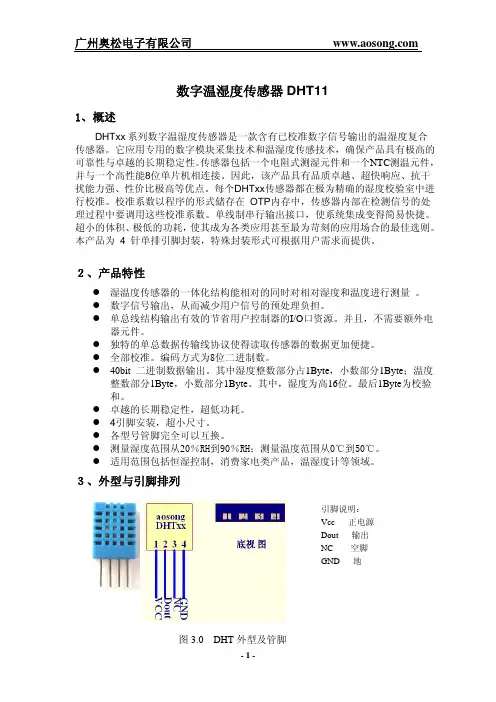
引脚说明1、VDD 供电3.3~5.5V DC2、DATA 串行数据,单总线3、NC 空脚4、GND 接地,电源负极一、产品概述DHT11数字温湿度传感器是一款含有已校准数字信号输出的温湿度复合传感器。
它应用专用的数字模块采集技术和温湿度传感技术,确保产品具有极高的可靠性与卓越的长期稳定性。
传感器包括一个电容式感二、应用范围暖通空调、除湿器、农业、冷链仓储、测试及检测设备、消费品、汽车、自动控制、数据记录器、气象站、家电、湿度调节器、医疗、其三、产品亮点成本低、长期稳定、相对湿度和温度测量、品质卓越、超快响应、抗干扰能力强、超长的信号传输距离、数字信号输出、精确校准。
四、外形尺寸(单位:mm )图1产品尺寸图五、产品参数5.1相对湿度表1相对湿度性能表5.2温度表2温度性能表5.3电气特性表3电气特性[1]此精度为出厂时检验时,传感器在25℃和5V,条件下测试的精度指标,其不包括迟滞和非线性,且只适合非冷凝环境。
[2]在25℃和1m/s气流的条件下,达到一阶响应63%所需要的时间。
[3]在挥发性有机混合物中数值可能会高一些。
见说明书应用储存信息。
六、典型电路图2DHT11典型电路图微处理器与DHT11的连接典型应用电路如上图(图2)所示,DATA上拉后与微处理器的I/O端口相连。
1、典型应用电路中建议连接线长度短于5m时用4.7K上拉电阻,大于5m时根据实际情况降低上拉电阻的阻值。
2、使用3.3V电压供电时连接线尽量短,接线过长会导致传感器供电不足,造成测量偏差。
3、每次读出的温湿度数值是上一次测量的结果,欲获取实时数据,需连续读取2次,但不建议连续多次读取传感器,每次读取传感器间隔大于2秒即可获得准确的数据。
4、电源部分如有波动,会影响到温度。
如使用开关电源,温度就会跳动。
#include<at89x52.h>#include<intrins.h>//加上这句下面的_nop_();就能用bit xianshiqiehuan;sbit dht11_dat=P1^6;unsigned char c,count, dht11temp,dht11dat;unsigned char dht11value[5];unsigned int x,y,z;unsigned char code dat[]={0xC0,0xF9,0xA4,0xB0,0x99,0x92,0x82,0xF8,0x80,0x90,0x88,};delay(){unsigned char a;for(a=200;a>0;a--);}display(unsigned char x){P0=dat[(x%100)/10];//十位P1_2=0;delay();P1_2=1;P0=dat[(x%100)%10];//个位P1_3=0;delay();P1_3=1;}delay_1s(){unsigned int i=50000;while(i--);}delay_10us() //10us{_nop_();_nop_();_nop_();_nop_();_nop_();_nop_();}void delayms(unsigned char x) //1ms单位延时程序{unsigned char j;while(x--){for(j=0;j<123;j++){;}}}read_dht11(){ unsigned char i;dht11_dat=1; _nop_(); //起始dht11_dat=0;//拉低总线delayms(18);//手册要求大于18msdht11_dat=1;//拉高总线等待dht11回应while(dht11_dat); // 等待dht11回应若有回应dht11_dat=0;往下执行while(!dht11_dat);//回应后dht11将总线拉低80us,过后又将总线拉高,进入下一步while(dht11_dat); //拉高80us 又变低,往下执行进入50us延时for(i=0;i<24;i++){while(!dht11_dat);//50us过后...... dht11_dat=1;往下执行delay_10us();delay_10us();delay_10us();//延时30us,查看总线是高是低,dht11temp=0; //先默认为0处理if(dht11_dat) dht11temp=1; //1处理dht11dat=dht11dat<<1; //必须先移动再或若先或再移本次数据就移动了dht11dat=dht11dat|dht11temp;dht11value[i/8]=dht11dat;while(dht11_dat);//如果处理的是1,30us过后总线还是1,那就在此等待总线变为0进入下一个50us低电平,不然会重复进行0处理}}main(){delay_1s(); //要求上电等1秒,让dht11稳定EA=1;//开放中断TMOD=0x01;//设T0 为16位计数方式ET0=1;//定时0中断允许TR0=1;//开启TR0while(1){if(!xianshiqiehuan) //显示温度display(dht11value[2]) ;else{display(dht11value[0]) ; //显示湿度P0=0x92&0x7f; //千位显S 代表湿度P1_0=0;delay();P1_0=1;}}}dingshi() interrupt 1 //定时器0服务程序{TH0=0;TL0=0;count++;if(count==55){count=0;read_dht11();xianshiqiehuan=~xianshiqiehuan; } //在切换显示时采集,以防中断采样带来的显示闪烁}。
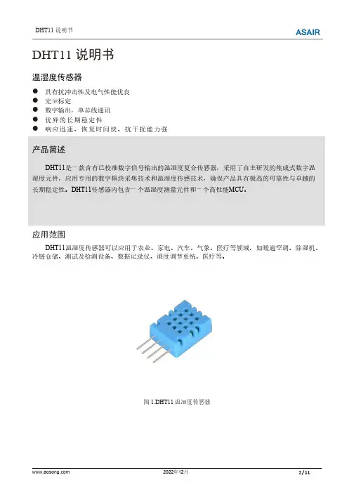
DHT11说明书温湿度传感器●具有抗冲击性及电气性能优良●完全标定●数字输出,单总线通讯●优异的长期稳定性●响应迅速、恢复时间快、抗干扰能力强产品简述DHT11是一款含有已校准数字信号输出的温湿度复合传感器,采用了自主研发的集成式数字温湿度元件,应用专用的数字模块采集技术和温湿度传感技术,确保产品具有极高的可靠性与卓越的长期稳定性。
DHT11传感器内包含一个温湿度测量元件和一个高性能MCU。
应用范围DHT11温湿度传感器可以应用于农业、家电、汽车、气象、医疗等领域,如暖通空调、除湿机、冷链仓储、测试及检测设备、数据记录仪、湿度调节系统、医疗等。
图1.DHT11温湿度传感器1.传感器性能1.1相对湿度表1.湿度特性表参数测试条件最小典型最大单位量程范围附加说明15-95%RH精度2--±5%RH重复性--±1-%RH互换性-完全互换响应时间3τ(63%)-<6-s迟滞--±0.3-%RH漂移4典型值-<0.5-%RH/yr 1.2电气特性表2.电气特性表符号参数测试条件最小典型最大单位VCC供电电压- 3.35 5.5VI平均电流5休眠-60-µA 测量-1000-µAV OL低电平输出电压I L6=5mA0-300mVV OH高电平输出电压Rp<25kΩ0.9*VCC-VCC VV IL低电平输入电压下降0-0.3VV IH高电平输入电压上升0.7-VCC VRp上拉电阻7VCC=5V1 4.7100kΩT S采样周期-2--s实际使用中的一些特性如功耗、输入和输出的高、低电平电压等都取决于供电电压。
在使用传感器时,要使系统获得鲁棒性,请确保各参数在表2所给出的范围内。
1正常工作范围:8~85%RH,超出此范围,传感器读数会有偏差(在90%RH湿度下60小时后,漂移>3%RH)。
工作范围进一步限定在-20~60℃。
2此精度为传感器出厂检验时,在25℃、VCC=5V条件下的测试精度。
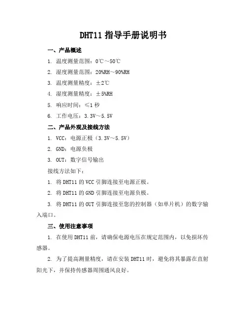
DHT11指导手册说明书一、产品概述1. 温度测量范围:0℃~50℃2. 湿度测量范围:20%RH~90%RH3. 温度测量精度:±2℃4. 湿度测量精度:±5%RH5. 响应时间:≤1秒6. 工作电压:3.3V~5.5V二、产品外观及接线方法1. VCC:电源正极(3.3V~5.5V)2. GND:电源负极3. OUT:数字信号输出接线方法如下:1. 将DHT11的VCC引脚连接至电源正极。
2. 将DHT11的GND引脚连接至电源负极。
3. 将DHT11的OUT引脚连接至您的控制器(如单片机)的数字输入端口。
三、使用注意事项1. 在使用DHT11前,请确保电源电压在规定范围内,以免损坏传感器。
2. 为了提高测量精度,请在安装DHT11时,避免将其暴露在直射阳光下,并保持传感器周围通风良好。
3. DHT11的OUT引脚输出的是数字信号,请确保控制器端的输入端口兼容数字信号。
4. 在长时间运行过程中,请定期检查DHT11的连接线是否牢固,防止因线缆松动导致的测量数据不准确。
DHT11指导手册说明书四、编程与通信协议1. 初始化:在开始通信前,请确保DHT11已经上电,并将控制器的输入端口设置为输入模式。
2. 开始信号:主机(控制器)将数据线拉低至少18毫秒,然后拉高,以唤醒DHT11。
3. DHT11响应:DHT11在检测到开始信号后,会拉低数据线80微秒,作为响应信号,随后拉高数据线80微秒,准备发送数据。
4. 数据接收:DHT11以每bit 50微秒的低电平表示“0”,以每bit 2628微秒的低电平后跟随70微秒的高电平表示“1”。
数据传输顺序为:湿度整数、湿度小数、温度整数、温度小数、校验和。
5. 校验和计算:校验和是前四个字节的简单累加,用于验证数据传输的正确性。
6. 编程示例:下面是一个简单的伪代码示例,用于读取DHT11的数据: void setup() {pinMode(DHT11_PIN, INPUT);}void loop() {int humidity = readDHT11Humidity();int temperature = readDHT11Temperature();// 处理温湿度数据}int readDHT11Humidity() {// 发送开始信号// 接收数据// 返回湿度值}int readDHT11Temperature() {// 发送开始信号// 接收数据// 返回温度值}五、安装与调试1. 安装位置:选择一个适合的环境进行安装,避免高温、高湿或直射阳光的地方,以确保测量准确性。
#include<reg51.h>#define uint unsigned int#define uchar unsigned charsbit TRH = P1^0;//温湿度传感器DHT11数据接入uchar str[]={0,0,0,0,0,0,0,0};uint TH,TL,RH,RL,CK;uint THc,TLc,RHc,RLc,CKc;uint xh,sum;// void delay(uchar s) //延时10us// {// uchar v;// for(;s>0;s--)// for(v=25;v>0;v--);// }void delay(uchar b) //误差0us{unsigned char a;for(;b>0;b--)for(a=2;a>0;a--);}//void delay1( )// 延时20ms//{//uchar x,y,z;//for(x=15;x>0;x--)//for(y=4;y>0;y--)//for(z=248;z>0;z--);//}void delay1(uchar c) //误差0us{unsigned char a,b;for(;c>0;c--)for(b=142;b>0;b--)for(a=2;a>0;a--);}void delay2()//数码管显示用的延时{uchar l,j,k;for(l=2;l>0;l--)for(j=4;j>0;j--)for(k=100;k>0;k--);}void start(){ TRH=1;delay(2);TRH=0; //主机拉低18msdelay1(20);TRH=1; //DATA总线由上拉电阻拉高主机延时20delay(3);}uchar receive(){ uchar i,temp;xh=0;while(TRH);for(i=0;i<8;i++){ while(!TRH);delay(3);if(TRH){ temp=1;while(TRH);}elsetemp=0;xh<<=1;xh|=temp;}return (xh);}void display(){uchar a[]={0xC0,0xF9,0xA4,0xB0,0x99,0x92,0x82,0xF8,0x80,0x90}; uchar m,n,s,i;m= str[3];//数码管显示部分n= str[4];s= str[5];while(1){for(i=0;i<10;i++){ if(m==i)m=a[i];}P0=m;P2=0x10;delay2();for(i=0;i<10;i++){ if(n==i)n=a[i];}P0=n-0X80;P2=0x20;delay2();for(i=0;i<10;i++){ if(s==i)s=a[i];}P0=s;P2=0x40;delay2();P0=0X9C;P2=0x80;delay2();}}void main(){while(1){start();TRH=1; // 读取数据并写入指令if(!TRH){while(!TRH); //判断DHT11发出80us 的低电平响应信号是否结束while(TRH);delay(8);RHc = receive(); //数据接收状态RLc = receive();THc = receive();TLc = receive();CKc = receive();}TRH=1;sum=(RHc+RLc+THc+TLc);//数据校验if(sum==CKc){ RH = RHc;RL = RLc;TH= THc;TL = TLc;CK = CKc;str[0] =RH/10; //湿度整数部分str[1] =RH%10;str[2] = RL/10 ;str[3] = TH/10; //温度整数部分str[4] = TH%10;str[5] = TL/10;}display();}}。
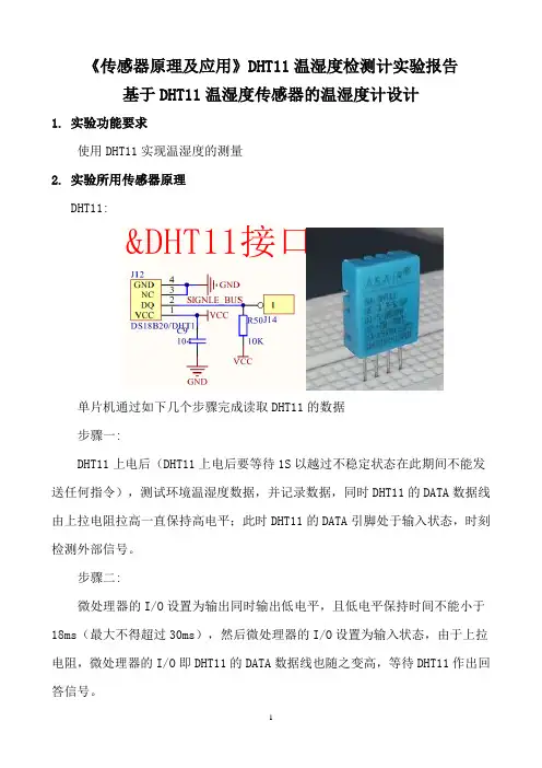
《传感器原理及应用》DHT11温湿度检测计实验报告基于DHT11温湿度传感器的温湿度计设计1.实验功能要求使用DHT11实现温湿度的测量2.实验所用传感器原理DHT11:单片机通过如下几个步骤完成读取DHT11的数据步骤一:DHT11上电后(DHT11上电后要等待1S以越过不稳定状态在此期间不能发送任何指令),测试环境温湿度数据,并记录数据,同时DHT11的DATA数据线由上拉电阻拉高一直保持高电平;此时DHT11的DATA引脚处于输入状态,时刻检测外部信号。
步骤二:微处理器的I/O设置为输出同时输出低电平,且低电平保持时间不能小于18ms(最大不得超过30ms),然后微处理器的I/O设置为输入状态,由于上拉电阻,微处理器的I/O即DHT11的DATA数据线也随之变高,等待DHT11作出回答信号。
步骤三:DHT11的DATA引脚检测到外部信号有低电平时,等待外部信号低电平结束,延迟后DHT11的DATA引脚处于输出状态,输出83微秒的低电平作为应答信号,紧接着输出87微秒的高电平通知外设准备接收数据,微处理器的I/O此时处于输入状态,检测到I/O有低电平(DHT11回应信号)后,等待87微秒的高电平后的数据接收。
步骤四:由DHT11的DATA引脚输出40位数据,微处理器根据I/O电平的变化接收40位数据,位数据“0”的格式为:54微秒的低电平和23-27微秒的高电平,位数据“1”的格式为:54微秒的低电平加68-74微秒的高电平。
低电平的时间一致,本质比较的是高电平的时间3.实验电路4.实验过程一.单片机上机后1s内不读取二. 主机(单片机)发送起始信号:1.主机先拉高data。
2.拉低data延迟18ms。
3.拉高data(通过此操作将单片机引脚设置为输入)。
三.DHT11收到起始信号后进行应答:拉低data,单片机读取到引脚被输出低电平持续80us后换为高电平,持续80us,直到高电平结束,意味着主机可以开始接受数据。
附录1:#include <regx52.h>#include <intrins.h>#include "DHT11.H"#include "DHT11.C"unsigned char range[4]={55,75,10,30}; //温湿度上下限初值unsigned char Humi_Temp_Tab[8]={6,9,0,0,7,8,0,0}; //数码管显示初值unsigned char numt1=0; //T1中断计数标志unsigned char numt0=0;unsigned char codeTab_Seg[10]={0x3f,0x06,0x5b,0x4f,0x66,0x6d,0x7d,0x07,0x7f,0x6f};//数码管段码 0-9unsigned char code Tab_Dig[8]={0x7f,0xbf,0xdf,0xef,0xf7,0xfb,0xfd,0xfe};//位选第一位到第八位unsigned char code units[4]={0x39,0x71,0x77,0x76}; //单位C/F/RH/**********************************************//* 温湿度采集函数 *//**********************************************/void getdata(){if(start_DHT11()){read_DHT11();}if(check_sum()){Humi_Temp_Tab[0]=DHT_data.DH_H/10;Humi_Temp_Tab[1]=DHT_data.DH_H%10;Humi_Temp_Tab[2]=DHT_data.DH_L/10; //存储湿度数据if(flag == 0){Humi_Temp_Tab[4]=DHT_data.T_H/10;Humi_Temp_Tab[5]=DHT_data.T_H%10;Humi_Temp_Tab[6]=DHT_data.T_L/10;//存储摄氏温度数据}else{Humi_Temp_Tab[4]=(9*DHT_data.T_H/5+32)/10;Humi_Temp_Tab[5]=(9*DHT_data.T_H/5+32)%10;Humi_Temp_Tab[6]=(18*DHT_data.T_H+320)%100%10;//存储华氏温度数据}}}/**********************************************//* 主函数 *//**********************************************/void main(){delay_ms(500); //先进行延时等待进入稳定状态P0 = 0;P1 = 0x0C; //初始化P1口EA = 0;TR1 = 0;TR0 = 0;TMOD = 0x11; //设置定时器 T0和T1,且工作方式都为方式1TH1 = (65536-5000)/256;TL1 = (65536-5000)%256;TH0 = (65536-2000)/256;TL0 = (65536-2000)%256; //设定初值2msTR1 = 1;TR0 = 1;EA = 1;ET0 = 1;ET1 = 1; //打开中断定时器T0和T1PT1 = 0;PT0 = 1; //强制设置优先级delay_ms(1000);while(1){if(DHT_data.DH_H<range[0]) //湿度小于下限{bee = 0;delay_ms(100);bee = 1;delay_ms(100);}if(DHT_data.DH_H>range[1]) //湿度大于上限{bee = 0;delay_ms(100);bee = 1;delay_ms(100);}if(DHT_data.T_H<range[2]) //温度小于下限{bee = 0;delay_ms(10);bee = 1;delay_ms(10);}if(DHT_data.T_H>range[3]) //温度大于上限{bee = 0;delay_ms(10);bee = 1;delay_ms(10);}}}/**********************************************//* 定时器T0中断 *//**********************************************/void T0_timer() interrupt 1{unsigned char KData = 0x00;TR0 = 0; //进入T0后将T0中断关闭TH0 = (65536-2000)/256;TL0 = (65536-2000)%256;switch(numt0){case 0: P0 = 0; Seg_ce = 1; Seg_ce = 0; //段选开关if(flag2 == 1)P0 = Tab_Seg[range[0]/10];//显示湿度下限的十位elseP0 = Tab_Seg[Humi_Temp_Tab[0]];//显示读取的湿度的十位Seg_ce = 1; Seg_ce = 0;.P0 = Tab_Dig[0]; //位选第一位Dig_ce = 1; Dig_ce = 0;numt0++;break;case 1: P0 = 0; Seg_ce = 1; Seg_ce = 0;if(flag2 == 1)P0 = Tab_Seg[range[0]%10];//显示湿度下限的个位elseP0 = Tab_Seg[Humi_Temp_Tab[1]];//显示读取的湿度的个位Seg_ce = 1; Seg_ce = 0;P0 = Tab_Dig[1]; //位选第二位Dig_ce = 1; Dig_ce = 0;numt0++;break;case 2: P0 = 0; Seg_ce = 1; Seg_ce = 0;if(flag2 == 1)P0 = Tab_Seg[range[1]/10];//显示湿度上限的十位elseP0 = units[2];//显示单位RSeg_ce = 1; Seg_ce = 0;P0 = Tab_Dig[2]; //位选第三位Dig_ce = 1; Dig_ce = 0;numt0++;break;case 3: P0 = 0; Seg_ce = 1; Seg_ce = 0;if(flag2 == 1)P0 = Tab_Seg[range[1]%10];//显示湿度上限的个位elseP0 = units[3]; //显示单位H Seg_ce = 1; Seg_ce = 0;P0 = Tab_Dig[3]; //位选第四位Dig_ce = 1; Dig_ce = 0;numt0++;break;case 4: P0 = 0; Seg_ce = 1; Seg_ce = 0;P0 = Tab_Dig[4];//位选第五位,且同时拉低键盘第四行Dig_ce = 1; Dig_ce = 0;Key_ce = 0;KData = P0; //扫描键盘第四行switch(KData){case 0xfe:case 0xfd:case 0xfb:case 0xf7:default:break;}while(KData != 0xff){KData = P0;}Key_ce = 1;if(flag2 == 1)P0 = Tab_Seg[range[2]/10];//显示温度下限的十位elseP0 = Tab_Seg[Humi_Temp_Tab[4]];//显示读取的温度的十位Seg_ce = 1; Seg_ce = 0;numt0++;break;case 5: P0 = 0; Seg_ce = 1; Seg_ce = 0;P0 = Tab_Dig[5];//位选第六位,且同时拉低键盘第三行Dig_ce = 1; Dig_ce = 0;Key_ce = 0;KData = P0;//扫描键盘第三行switch(KData){case 0xfe:if(range[0]<range[1]&&flag2==1)range[0]++;break; //湿度下限加case 0xfd:if(range[1]<90&&flag2==1)range[1]++;break; //湿度上限加case 0xfb:if(range[2]<range[3]&&flag2==1range[2]++;break; //温度下限加case 0xf7:if(range[3]<50&&flag2==1)range[3]++;break; //温度上限加default:break;}while(KData != 0xff){KData = P0;}Key_ce = 1;if(flag2 == 1)P0 = Tab_Seg[range[2]%10];//显示温度下限的个位elseP0 = Tab_Seg[Humi_Temp_Tab[5]]-0x80; //显示读取温度的个位(带小数点的)Seg_ce = 1; Seg_ce = 0;numt0++;break;case 6: P0 = 0; Seg_ce = 1; Seg_ce = 0;P0 = Tab_Dig[6];//位选第七位,且同时拉低键盘第二行Dig_ce = 1; Dig_ce = 0;Key_ce = 0;KData = P0; //扫描键盘第二行switch(KData){case 0xfe:if(range[0]>20&&flag2==1)range[0]--;break; //湿度下限减case 0xfd:if(range[0]<range[1]&&flag2==1)range[1]--;break; //湿度上限减case 0xfb:if(range[2]>0&&flag2==1)range[2]--;break; //温度下限减case 0xf7:if(range[2]<range[3]&&flag2==1)range[3]--;break; //温度上限减default:break;}while(KData != 0xff){KData = P0;}Key_ce = 1;if(flag2 == 1)P0 = Tab_Seg[range[3]/10];//显示温度上限的十位elseP0 = Tab_Seg[Humi_Temp_Tab[6]];//显示读取温度的小数位的十位Seg_ce = 1; Seg_ce = 0;numt0++;break;case 7: P0 = 0; Seg_ce = 1; Seg_ce = 0;P0 = Tab_Dig[7];//位选第八位,且同时拉低键盘第一行Dig_ce = 1; Dig_ce = 0;Key_ce = 0;KData = P0; //扫描键盘第一行switch(KData){case 0xfe:flag2 = ~flag2;TR1 = ~TR1;break;//进入和退出限制调整模式case 0xfd:flag = ~flag;break;//进行华氏摄氏温度的转换设置case 0xfb:case 0xf7:default:break;}while(KData != 0xff){KData = P0;}Key_ce = 1;if(flag == 0&&flag2 == 0)P0 = units[0]; //显示单位Celse if(flag == 1&&flag2 == 0)P0 = units[1]; //显示单位Felse if(flag2 == 1)P0 = Tab_Seg[range[3]%10];//显示温度上限的个位Seg_ce = 1; Seg_ce = 0;numt0 = 0;break;default:numt0 = 0;break;}TR0 = 1; //打开T0}/**********************************************//* 定时器T1中断 *//**********************************************/void T1_timer() interrupt 3{TR1 = 0; //关闭T0TH1 = (65536-50000)/256;TL1 = (65536-50000)%256;if(numt1 == 25){getdata(); //采集数据numt1 = 0;}elsenumt1++;TR1 = 1; //打开T0}#ifndef __DHT11_h__#define __DHT11_h__#include <REGX52.H>/**********************************************//* 引脚定义 *//**********************************************/sbit DHT_bus = P2^0 ; //DHT11数据传输口sbit Key_ce=P1^3; //按键输出使能sbit Seg_ce=P1^0; //段选位sbit Dig_ce=P1^1; //位选位sbit bee = P2^1; //蜂鸣器控制口/**********************************************//* 函数声明 *//**********************************************/bit start_DHT11(void); //开始void read_DHT11(void); //读取void delay_20us(void); //20us延时void delay_ms(unsigned char m); //N ms延时bit check_sum(void); //和校验/**********************************************//* 宏定义 *//**********************************************/#define HIGH 1#define LOW 0/**********************************************//* 变量定义 *//**********************************************/#define DHT_timeover 5 //高电平维持时间,用于识别“数据0”和“数据1”bit flag2 = 0; //设置调节上下限模式转换标志bit flag=0; //设置摄氏和华氏温度模式转换标志/**********************************************//* 结构体 *//**********************************************/struct DHT_data{unsigned char DH_H; //湿度整数unsigned char DH_L; //湿度小数unsigned char T_H; //温度整数unsigned char T_L; //温度小数unsigned char Checksum; //校验和}DHT_data;#endif#include "DHT11.h"#include <intrins.h>/**********************************************//* 开始 DHT11 温湿度计 *//* 输入:无 *//* 输出:应答标志 0:应答失败 1:应答成功 *//**********************************************/bit start_DHT11(void){bit DHT_start;DHT_start = 0;DHT_bus = HIGH;DHT_bus = LOW; //拉低18ms以上delay_ms(18);TR0 = 0;DHT_bus = HIGH;delay_20us();delay_20us(); //拉高20~40uswhile(!DHT_bus){DHT_start = 1;} //DHT应答,DHT拉低80us后拉高80us,然后开始传输数据//数据(40bit)=8bit湿度整数+8bit湿度小数+8bit温度整数+8bit 温度小数+8bit校验和while(DHT_bus){};return(DHT_start); //应答成功返回1}/**********************************************//* 读取 DHT11 温湿度计 *//* 读取结果存在DHT_data结构体内 *//* 输入:无输出:无 *//**********************************************/void read_DHT11(void){unsigned char m,n,timer_dht;unsigned char *p;p=&DHT_data.DH_H; //数据放在DHT_date的结构体中for(m=0;m<5;m++){for(n=0;n<8;n++){while(~DHT_bus); //DHT拉低12-14us表示1bit数据开始timer_dht=0x00;while(DHT_bus) //随后DHT拉高总线,单片机通过高电平维持的时间判断“数据0”还是“数据1”{ //数据0维持26~28us高电平,数据1维持116~118us高电平timer_dht++; //由于此处对延时时间的长度要求很高,所以采用另一种办法判断}if(timer_dht>DHT_timeover){*p<<=1;*p|=0x01;}else{*p<<=1;*p&=0xfe;}}p++;}TR0 = 1;}/**********************************************//* 20us 精确延时 *//* 51用在12Mhz晶振下 *//* 调用函数使用LCALL和RET指令,共花费4个周期 *//* 因此只有16个NOP *//**********************************************/.void delay_20us(void){_nop_ ();_nop_ ();_nop_ ();_nop_ ();_nop_ ();_nop_ ();_nop_ ();_nop_ ();_nop_ ();_nop_ ();_nop_ ();_nop_ ();_nop_ ();_nop_ ();_nop_ ();_nop_ ();}/**********************************************//* N ms 延时 *//* while()额外占用约5周期 *//* 因此内层while(40--)20us 大约1ms *//* Nms延时函数(未测试) *//**********************************************/void delay_ms(unsigned char m){unsigned char n = 38;while(m--){while(n--){delay_20us();}}}/**********************************************//* 校验和判断 *//* 校验位 = 湿度整数位+湿度小数位+温度整数位+温度小数位之和 *//* 校验正确返回:1 失败返回:0 *//**********************************************/bit check_sum(void){if(DHT_data.Checksum==(DHT_data.DH_H+DHT_data.DH_L+DHT_data.T _H+DHT_data.T_L))return(1); //校验正确elsereturn(0); //校验失败}Word 资料。
DHT11模块测量温湿度的流程概述本文将介绍D HT11模块的使用方法,包括连接电路、读取数据的流程以及温湿度的计算方法。
连接电路首先,我们需要将DH T11模块与单片机进行连接。
需要使用3个引脚:V C C、GN D和数据引脚。
具体的连接方式如下:-将DH T11模块的VC C引脚连接到单片机的3.3V或5V电源引脚上。
-将DH T11模块的GN D引脚连接到单片机的地(GN D)引脚上。
-将DH T11模块的数据引脚连接到单片机的任意可用的数字引脚上。
连接完成后,我们可以开始测量温湿度了。
测量温湿度的流程1.初始化在开始测量之前,我们需要对DH T11模块进行初始化。
初始化的步骤包括向D HT11发送一个低电平的信号,并延时至少18毫秒。
这个低电平信号将引导D HT11进入测量模式。
2.接收数据初始化完成后,D HT11模块会将测量到的温湿度数据以串行的形式发送回来。
我们需要准备好接收数据的缓冲区,并准备接收数据的引脚。
3.解析数据接收到数据后,我们需要对它进行解析。
D H T11模块发送的数据包括温度和湿度的整数部分和小数部分。
我们需要按照一定的规则将这些数据进行解析,得到最终的温度和湿度数值。
4.计算温湿度解析完数据后,我们可以根据DH T11模块的计算公式来得到真实的温度和湿度数值。
这个公式在D HT11模块的数据手册中有详细的说明。
5.显示结果最后,我们可以将测量得到的温湿度数据显示在单片机的L CD屏幕上,或者通过串口进行输出。
以上就是使用DH T11模块测量温湿度的完整流程。
通过连接电路、初始化、接收数据、解析数据和计算温湿度,我们可以准确地测量环境中的温度和湿度,为后续的应用提供数据支持。
小结本文介绍了使用D HT11模块测量温湿度的流程。
通过连接电路、初始化、接收数据、解析数据和计算温湿度,我们可以轻松地获取环境的温湿度数据。
这对于许多物联网和环境监测应用来说是非常重要的。
希望通过本文的介绍,你能够更好地理解和应用DH T11模块。
Temperature and humidity module DHT11 Product Manual1、Product OverviewDHT11digital temperature and humidity sensor is a composite Sensor contains a calibrated digital signal output of the temperature and humidity. Application of a dedicated digital modules collection technology and the temperature and humidity sensing technology, to ensure that the product has high reliability and excellent long-term stability. The sensor includes a resistive sense of wet components and an NTC temperature measurement devices, and connected with ahigh-performance 8-bit microcontroller.2、ApplicationsHVAC, dehumidifier, testing and inspection equipment, consumer goods, automotive, automatic control, data loggers, weather stations, home appliances, humidity regulator, medical and other humidity measurement and control.3、FeaturesLow cost, long-term stability, relative humidity and temperature measurement, excellent quality, fast response, strong anti-interference ability, long distance signal transmission, digital signal output, and precise calibration.4、Dimensions (unit: mm)5、Product parametersRelative humidityResolution: 16BitRepeatability: ±1% RHAccuracy: At 25℃±5% RHInterchangeability: fully interchangeableResponse time: 1 / e (63%) of 25℃6s1m / s air 6sHysteresis: <± 0.3% RHLong-term stability: <± 0.5% RH / yr inTemperatureResolution: 16BitRepeatability: ±0.2℃Range: At 25℃±2℃Response time: 1 / e (63%) 10SElectrical CharacteristicsPower supply: DC 3.5~5.5VSupply Current: measurement 0.3mA standby 60μA Sampling period: more than 2 secondsPin Description1, the VDD power supply 3.5~5.5V DC2 DATA serial data, a single bus3, NC, empty pin4, GND ground, the negative power6、Typical circuitMicroprocessor and DHT11 of connection typical application circuit as shown above, DATA pull the microprocessor I / O ports are connected.1.Typical application circuit recommended in the short cable length of 20 meters on the 5.1Kpull-up resistor, the resistance of greater than 20 meters under the pull-up resistor on the lower of the actual situation.2.When using a3.5V voltage supply cable length shall not be greater than 20cm. Otherwise, the line voltage drop will cause the sensor power supply shortage, caused by measurement error.3.Each read out the temperature and humidity values are the results of the last measurement For real-time data, sequential read twice, but is not recommended to repeatedly read the sensors, each read sensor interval is greater than 5 seconds can be obtainedaccurate data.7、Serial communication instructions (single-wire bi-directional)◎Single bus DescriptionDHT11uses a simplified single-bus communication. Single bus that only one data line, the system of data exchange, control by a single bus to complete. Device (master or slave) through an open-drain or tri-state port connected to the data line to allow the device does not send data to release the bus, while other devices use the bus; single bus usually require an external one about 5.1kΩ pull-up resistor, so that when the bus is idle, its status is high. Because they are the master-slave structure, and only when the host calls the slave, the slave can answer, the host access devices must strictly follow the single-bus sequence, if the chaotic sequence, the device will not respond to the host.◎Single bus to transfer data definedDATA For communication and synchronization between the microprocessor and DHT11, single-bus data format, a transmission of 40 data, the high first-out.Data format:The 8bit humidity integer data + 8bit the Humidity decimal data +8 bit temperature integer data + 8bit fractional temperature data +8 bit parity bit.◎Parity bit data definition“8bit humidity integer data + 8bit humidity decimal data +8 bit temperature integer data + 8bit temperature fractional data”8bit checksum is equal to the results of the last eight.Example 1: 40 data is received:0011 0101 0000 0000 0001 1000 0000 0000 0100 1101 High humidity 8 Low humidity 8 High temp. 8 Low temp. 8 Parity bit Calculate:0011 0101+0000 0000+0001 1000+0000 0000= 0100 1101Received data is correct:Humidity:0011 0101=35H=53%RHTemperature:0001 1000=18H=24℃Example 2: 40 data is received:0011 0101 0000 0000 0001 1000 0000 0000 0100 1001 High humidity 8 Low humidity 8 High temp. 8 Low temp. 8 Parity bit Calculate:0011 0101+0000 0000+0001 1000+0000 0000=0100 110101001101≠0100 1001The received data is not correct, give up, to re-receive data.◎Data Timing DiagramUser host (MCU) to send a signal, DHT11 converted from low-power mode to high-speed mode, until the host began to signal the end of the DHT11 send a response signal to send 40bit data, and trigger a letter collection. The signal is sent as shown.Data Timing DiagramNote: The host reads the temperature and humidity data from DHT11 always the last measured value, such as twice the measured interval of time is very long, continuous read twice to the second value of real-time temperature and humidity values.◎Peripherals read stepsCommunication between the master and slave can be done through the following steps (peripherals (such as microprocessors) read DHT11 the data of steps).Step 1:After power on DHT11 (DHT11 on after power to wait 1S across the unstable state during this period can not send any instruction), the test environment temperature and humidity data, and record the data, while DHT11 the DATA data lines pulled by pull-up resistor has been to maintainhigh; the DHT11 the DATA pin is in input state, the moment of detection of external signals.Step 2:Microprocessor I / O set to output at the same time output low, and low hold time can not be less than 18ms, then the microprocessor I / O is set to input state, due to the pull-up resistor, a microprocessor/ O DHT11 the dATA data lines also will be high, waiting DHT11 to answer signal, send the signal as shown:Host sends a start signalStep 3:DATA pin is detected to an external signal of DHT11 low, waiting for external signal low end the delay DHT11 DATA pin in the output state, the output low of 80 microseconds as the response signal, followed by the output of 80 micro-seconds of high notification peripheral is ready to receive data, the microprocessor I / O at this time in the input state is detected the I / O low (DHT11 response signal), wait 80 microseconds highdata receiving and sending signals as shown:Step 4:Output by DHT11 the DATA pin 40, the microprocessor receives 40 data bits of data "0" format: the low level of 50 microseconds and 26-28 microseconds according to the changes in the I / O levellevel, bit data "1" format: the high level of low plus, 50 microseconds to 70 microseconds. Bit data "0", "1" signal format as shown:End signal:Continue to output the low 50 microseconds after DHT11 the DATA pin output 40 data, and changed the input state, along with pull-up resistor goes high. But DHT11 internal re-test environmental temperature and humidity data, and record the data, waiting for the arrival of the external signal.8、Application of information1. Work and storage conditionsOutside the sensor the proposed scope of work may lead to temporary drift of the signal up to 300%RH. Return to normal working conditions, sensor calibration status will slowly toward recovery. To speed up the recovery process may refer to "resume processing". Prolonged use of non-normal operating conditions, will accelerate the aging of the product.Avoid placing the components on the long-term condensation and dry environment, as well as the following environment.A, salt sprayB, acidic or oxidizing gases such as sulfur dioxide, hydrochloric acidRecommended storage environmentTemperature: 10 ~ 40 ℃Humidity: 60% RH or less2. The impact of exposure to chemicalsThe capacitive humidity sensor has a layer by chemical vapor interference, the proliferation of chemicals in the sensing layer may lead to drift and decreased sensitivity of the measured values. In a pure environment, contaminants will slowly be released. Resume processing as described below will accelerate this process. The high concentration of chemical pollution (such as ethanol) will lead to the complete damage of the sensitive layer of the sensor.3. The temperature influenceRelative humidity of the gas to a large extent dependent on temperature. Therefore, in the measurement of humidity, should be to ensure that the work of the humidity sensor at the same temperature. With the release of heat of electronic components share a printed circuit board, the installation should be as far as possible the sensor away from the electronic components and mounted below the heat source, while maintaining good ventilation of the enclosure. To reduce the thermal conductivity sensor and printed circuit board copper plating should be the smallest possible, and leaving a gap between the two.4. Light impactProlonged exposure to sunlight or strong ultraviolet radiation, and degrade performance.5. Resume processingPlaced under extreme working conditions or chemical vapor sensor, which allows it to return to the status of calibration by the following handler. Maintain two hours in the humidity conditions of 45℃and <10% RH (dry); followed by 20-30℃and> 70% RH humidity conditions to maintain more than five hours.6. Wiring precautionsThe quality of the signal wire will affect the quality of the voltage output, it is recommended to use high quality shielded cable.7. Welding informationManual welding, in the maximum temperature of 300℃under the conditions of contact time shall be less than 3 seconds.8. Product upgradesDetails, please the consultation Aosong electronics department.9、The license agreementWithout the prior written permission of the copyright holder, shall not in any form or by any means, electronic or mechanical (including photocopying), copy any part of this manual, nor shall its contents be communicated to a third party. The contents are subject to change without notice.The Company and third parties have ownership of the software, the user may use only signed a contract or software license.10、Warnings and personal injuryThis product is not applied to the safety or emergency stop devices, as well as the failure of the product may result in injury to any other application, unless a particular purpose or use authorized. Installation, handling, use or maintenance of the product refer to product data sheets and application notes. Failure to comply with this recommendation may result in death and serious personal injury. The Company will bear all damages resulting personal injury or death, and waive any claims that the resulting subsidiary company managers and employees and agents, distributors, etc. that may arise, including: a variety of costs, compensation costs, attorneys' fees, and so on.11、Quality AssuranceThe company and its direct purchaser of the product quality guarantee period of three months (from the date of delivery). Publishes the technical specifications of the product data sheet shall prevail. Within the warranty period, the product was confirmed that the quality is really defective, the company will provide free repair or replacement. The user must satisfy the following conditions:①The product is found defective within 14 days written notice to the Company;②The product shall be paid by mail back to the company;③The product should be within the warranty period.The Company is only responsible for those used in the occasion of the technical condition of the product defective product. Without any guarantee, warranty or written statement of its products used in special applications. Company for its products applied to the reliability of the product or circuit does not make any commitment.。

DHT11传感器规格说明DHT11传感器规格说明1. 引言在当今科技发展的时代,传感器在各个领域中扮演着重要的角色。
其中,DHT11传感器是一款常见的数字温湿度传感器,被广泛应用于气象、环境监测、农业以及智能家居等领域。
本文将深入探讨DHT11传感器的规格说明,包括其工作原理、技术指标、应用范围等方面。
2. 工作原理DHT11传感器采用单总线数据传输方式,结合专用硬件和算法,实现对温度和湿度的精准测量。
其内部集成了一个温度传感器和一个湿度传感器,并通过内部的数据处理单元将测量值转换为数字信号输出。
DHT11传感器的工作原理可以简单描述如下:通过调用传感器的引脚,控制传感器进行工作,并从其输出引脚读取数据。
具体的工作原理涉及到精密的温度和湿度测量技术,超出了本文的讨论范围。
3. 技术指标DHT11传感器具有以下技术指标,这些指标直接影响着传感器的性能和可靠性:3.1 温度测量范围:DHT11传感器可以在-20摄氏度至60摄氏度的温度范围内进行测量。
超出该范围,传感器可能无法提供准确的测量结果。
3.2 湿度测量范围:DHT11传感器可以在20%RH至90%RH的湿度范围内进行测量。
超出该范围,传感器的测量结果可能不准确。
3.3 温度测量精度:DHT11传感器的温度测量精度约为±2摄氏度。
这意味着传感器提供的温度测量结果与实际温度之间的误差在±2摄氏度之内。
3.4 湿度测量精度:DHT11传感器的湿度测量精度约为±5%RH。
这意味着传感器提供的湿度测量结果与实际湿度之间的误差在±5%RH之内。
3.5 供电电压:DHT11传感器的工作电压范围为3.3V至5.5V。
在提供足够的电源供应下,传感器能够正常工作并提供准确的测量结果。
4. 应用范围DHT11传感器由于其简单、易用且成本低廉的特点,在各个领域有着广泛的应用。
以下是DHT11传感器常见的应用场景:4.1 气象数据采集:DHT11传感器可以用于实时采集和监测室内和室外的温度和湿度数据。
dht11使用手册摘要:一、产品简介二、功能特点三、使用方法四、注意事项五、故障处理六、售后服务正文:一、产品简介DHT11是一款具有高精度、低功耗的温湿度传感器。
它广泛应用于家庭、办公室、实验室等场所,可以帮助用户实时了解环境温湿度,为舒适生活提供科学依据。
本产品具有小巧的体积、简单的接口和稳定的性能,易于集成到各种智能设备中。
二、功能特点1.测量范围:温度-40℃~+70℃,湿度0%~100%2.精度:温度±0.5℃,湿度±5%3.响应时间:1秒4.低功耗:小于1μA5.抗干扰能力强:能适应各种恶劣环境6.自带校准功能:确保测量数据的准确性三、使用方法1.连接电路:将DHT11的VCC、GND和DATA引脚分别连接到电源、地和数据处理模块。
2.数据读取:通过I2C或SPI接口从DHT11读取温湿度数据。
3.数据处理:对读取到的数据进行处理,得到实际温湿度值。
4.显示和应用:将处理后的数据显示在相关设备上,或根据需求进行应用。
四、注意事项1.避免暴力拆卸和损坏传感器元件。
2.连接线路时,确保接头牢固可靠,防止松动。
3.传感器应安装在通风、避免阳光直射的地方。
4.定期检查传感器连接和电路,确保正常工作。
五、故障处理1.若传感器无法正常工作,首先检查电路连接是否正确。
2.若连接正常,检查电源电压是否稳定。
3.若电源电压正常,尝试重新校准传感器。
4.若仍无法正常工作,请联系售后服务。
六、售后服务本公司为您提供完善的售后服务,如有任何疑问或需求,请随时联系。
我们将尽快解决您的问题,确保您的权益。
总之,DHT11是一款性能优越的温湿度传感器,通过本文的介绍,相信您已经了解了它的功能特点和使用方法。
在实际应用中,请注意相关事项,确保传感器稳定工作。
如遇到故障,可参照本文进行处理。
D H T11中文说明书-CAL-FENGHAI.-(YICAI)-Company One1数字温湿度传感器DHT11►相对湿度和温度测量►全部校准,数字输出►卓越的长期稳定性►无需额外部件►超长的信号传输距离►超低能耗►4 引脚安装►完全互换DHT11产品概述DHT11数字温湿度传感器是一款含有已校准数字信号输出的温湿度复合传感器。
它应用专用的数字模块采集技术和温湿度传感技术,确保产品具有极高的可靠性与卓越的长期稳定性。
传感器包括一个电阻式感湿元件和一个NTC测温元件,并与一个高性能8位单片机相连接。
因此该产品具有品质卓越、超快响应、抗干扰能力强、性价比极高等优点。
每个DHT11传感器都在极为精确的湿度校验室中进行校准。
校准系数以程序的形式储存在OTP内存中,传感器内部在检测信号的处理过程中要调用这些校准系数。
单线制串行接口,使系统集成变得简易快捷。
超小的体积、极低的功耗,信号传输距离可达20米以上,使其成为各类应用甚至最为苛刻的应用场合的最佳选则。
产品为 4 针单排引脚封装。
连接方便,特殊封装形式可根据用户需求而提供。
应用领域►暖通空调►测试及检测设备►汽车►数据记录器►消费品►自动控制►气象站►家电►湿度调节器►医疗►除湿器型号测量范围测湿精度测温精度分辨力封装DHT1120-90%RH 0-50℃±5%RH±2℃14针单排直插1、传感器性能说明参数条件Min Typ Max单位湿度分辨率111%RH16Bit重复性±1%RH精度25℃±4%RH0-50℃±5%RH互换性可完全互换量程范围0℃3090%RH25℃2090%RH50℃2080%RH61015S响应时间1/e(63%)25℃,1m/s 空气迟滞±1%RH长期稳定性典型值±1%RH/yr 温度分辨率111℃161616Bit重复性±1℃精度±1±2℃量程范围050℃响应时间1/e(63%)630S建议连接线长度短于20米时用5K上拉电阻,大于20米时根据实际情况使用合适的上拉电阻3、电源引脚DHT11的供电电压为3-。
DHT11 温湿度传感器avr nega 16 c程序#include <reg51.h>#include <intrins.h>//typedef unsigned char U8; /* defined for unsigned 8-bits integer variable 无符号8位整型变量*/typedef signed char S8; /* defined for signed 8-bits integer variable 有符号8位整型变量*/typedef unsigned int U16; /* defined for unsigned 16-bits integer variable 无符号16位整型变量*/typedef signed int S16; /* defined for signed 16-bits integer variable 有符号16位整型变量*/typedef unsigned long U32; /* defined for unsigned 32-bits integer variable 无符号32位整型变量*/typedef signed long S32; /* defined for signed 32-bits integer variable 有符号32位整型变量*/typedef float F32; /* single precision floating point variable (32bits) 单精度浮点数(32位长度)*/typedef double F64; /* double precision floating point variable (64bits) 双精度浮点数(64位长度)*///#define uchar unsigned char#define uint unsigned int#define Data_0_time 4//----------------------------------------------////----------------IO口定义区--------------------////----------------------------------------------//sbit P2_0 = P2^0 ;sbit P2_1 = P2^1 ;sbit P2_2 = P2^2 ;sbit P2_3 = P2^3 ;//----------------------------------------------////----------------定义区--------------------////----------------------------------------------//U8 U8FLAG,k;U8 U8count,U8temp;U8 U8T_data_H,U8T_data_L,U8RH_data_H,U8RH_data_L,U8checkdata;U8U8T_data_H_temp,U8T_data_L_temp,U8RH_data_H_temp,U8RH_data_L_temp,U8che ckdata_temp;U8 U8comdata;U8 outdata[5]; //定义发送的字节数U8 indata[5];U8 count, count_r=0;U8 str[5]={"RS232"};U16 U16temp1,U16temp2;SendData(U8 *a){outdata[0] = a[0];outdata[1] = a[1];outdata[2] = a[2];outdata[3] = a[3];outdata[4] = a[4];count = 1;SBUF=outdata[0];}void Delay(U16 j){ U8 i;for(;j>0;j--){for(i=0;i<27;i++);}}void Delay_10us(void){U8 i;i--;i--;i--;i--;i--;i--;}void COM(void){U8 i;for(i=0;i<8;i++){U8FLAG=2;//----------------------P2_1=0 ; //TP2_1=1 ; //T//----------------------while((!P2_0)&&U8FLAG++);Delay_10us();Delay_10us();// Delay_10us();U8temp=0;if(P2_0)U8temp=1;U8FLAG=2;while((P2_0)&&U8FLAG++);//----------------------P2_1=0 ; //TP2_1=1 ; //T//----------------------//超时则跳出for循环if(U8FLAG==1)break;//判断数据位是0还是1// 如果高电平高过预定0高电平值则数据位为1U8comdata<<=1;U8comdata|=U8temp; //0}//rof}//--------------------------------//-----湿度读取子程序------------//--------------------------------//----以下变量均为全局变量--------//----温度高8位== U8T_data_H------//----温度低8位== U8T_data_L------//----湿度高8位== U8RH_data_H-----//----湿度低8位== U8RH_data_L-----//----校验8位== U8checkdata-----//----调用相关子程序如下----------//---- Delay();, Delay_10us();,COM();//--------------------------------void RH(void){//主机拉低18msP2_0=0;Delay(180);P2_0=1;//总线由上拉电阻拉高主机延时20usDelay_10us();Delay_10us();Delay_10us();Delay_10us();//主机设为输入判断从机响应信号P2_0=1;//判断从机是否有低电平响应信号如不响应则跳出,响应则向下运行if(!P2_0) //T !{U8FLAG=2;//判断从机是否发出80us 的低电平响应信号是否结束while((!P2_0)&&U8FLAG++);U8FLAG=2;//判断从机是否发出80us 的高电平,如发出则进入数据接收状态while((P2_0)&&U8FLAG++);//数据接收状态COM();U8RH_data_H_temp=U8comdata;COM();U8RH_data_L_temp=U8comdata;COM();U8T_data_H_temp=U8comdata;COM();U8T_data_L_temp=U8comdata;COM();U8checkdata_temp=U8comdata;P2_0=1;//数据校验U8temp=(U8T_data_H_temp+U8T_data_L_temp+U8RH_data_H_temp+U8RH_data_L_t emp);if(U8temp==U8checkdata_temp){U8RH_data_H=U8RH_data_H_temp;U8RH_data_L=U8RH_data_L_temp;U8T_data_H=U8T_data_H_temp;U8T_data_L=U8T_data_L_temp;U8checkdata=U8checkdata_temp;}//fi}//fi}//----------------------------------------------//main()功能描述: AT89C51 11.0592MHz 串口发//送温湿度数据,波特率9600//----------------------------------------------void main(){U8 i,j;//uchar str[6]={"RS232"};/* 系统初始化*/TMOD = 0x20; //定时器T1使用工作方式2TH1 = 253; // 设置初值TL1 = 253;TR1 = 1; // 开始计时SCON = 0x50; //工作方式1,波特率9600bps,允许接收ES = 1;EA = 1; // 打开所以中断TI = 0;RI = 0;SendData(str) ; //发送到串口Delay(1); //延时100US(12M晶振)while(1){//------------------------//调用温湿度读取子程序RH();//串口显示程序//--------------------------str[0]=U8RH_data_H;str[1]=U8RH_data_L;str[2]=U8T_data_H;str[3]=U8T_data_L;str[4]=U8checkdata;SendData(str) ; //发送到串口//读取模块数据周期不易小于2SDelay(20000);}//elihw}// mainvoid RSINTR() interrupt 4 using 2 {U8 InPut3;if(TI==1) //发送中断{TI=0;if(count!=5) //发送完5位数据{SBUF= outdata[count];count++;}}if(RI==1) //接收中断{InPut3=SBUF;indata[count_r]=InPut3;count_r++;RI=0;if (count_r==5)//接收完4位数据{//数据接收完毕处理。
dht11使用手册DHT11温湿度传感器是一种数字温湿度传感器,可以用于测量环境中的温度和湿度。
在使用DHT11之前,您需要了解一些基本的使用说明。
以下是DHT11的使用手册:1. 连接电路:将DHT11传感器的VCC引脚连接到5V电源,GND引脚连接到地线,以及数据引脚连接到微控制器的数字输入引脚。
还可以使用一个10K上拉电阻将数据引脚连接到5V电源。
2. 编程:使用适当的编程语言和库来读取DHT11传感器的数据。
您可以使用Arduino、Python、Raspberry Pi等平台来编写代码。
3. 初始化传感器:在开始读取数据之前,需要初始化传感器。
初始化可以通过发送一个低电平信号(例如设置为输出模式并放置在低电平)给传感器来完成。
4. 读取数据:通过将数据引脚设置为输入模式并读取从传感器发送的数字信号来读取温湿度数据。
接收到的数据包括温度值和湿度值。
您可以使用相关的库函数来解析这些数据。
5. 数据解析:DHT11传感器发送的数据是二进制编码的,您需要根据其协议来解析数据。
协议通常包括一个起始位、温度值、湿度值和校验和。
解析数据时,请确保校验和与其他数据一致,以确保数据的准确性。
6. 错误处理:在使用DHT11传感器时,可能会遇到一些错误。
例如传感器无响应、数据错误等。
为了确保测量结果的准确性和可靠性,您需要正确处理这些错误,例如重新尝试读取数据或检查传感器连接。
7. 数据显示:将读取的温湿度数据显示在适当的显示器上,如液晶显示器、终端窗口等。
您可以使用相应的库函数来将数据显示在你选择的显示设备上。
以上是DHT11温湿度传感器的基本使用手册。
根据特定的硬件和软件平台的要求,您可能需要进一步的参考资料来详细了解如何使用DHT11。
DHT11温湿度传感器C程序
说明:
DHT11温湿度传感器只有整数位没有小数,传感器内部小数位留空备用,使用该程序时,只需要在while循环里面调用RH函数即可,间隔时间大于1秒,读取以下几个效验后的变量可以获取温湿度值:
U8RH_data_H 湿度高8位整数位
U8RH_data_L 湿度低8位小数位(空的)
U8T_data_H 温度高8位整数位
U8T_data_L 温度低8位整数位(空的)
1,如果是用数码管显示,按时序延时18毫秒后如果有中断得关中断,取完40个Bit数据后开中断,防止MCU内部中断打断时序时间,引起读数误差或
读不出来的问题,LCD显示器无需该操作。
2,循环读取传感器时间得大于1秒,否则读不准。
自己做的实验板温度25,湿度45%
#include <reg52.h>
#include <intrins.h>
//
typedef unsigned char U8; /* defined for unsigned 8-bits integer variable 无符号8位整型变量*/
typedef signed char S8; /* defined for signed 8-bits integer variable 有符号8位整型变量*/
typedef unsigned int U16; /* defined for unsigned 16-bits integer variable 无符号16
位整型变量*/
typedef signed int S16; /* defined for signed 16-bits integer variable 有符号16位整型变量*/
typedef unsigned long U32; /* defined for unsigned 32-bits integer variable 无符号32位整型变量*/
typedef signed long S32; /* defined for signed 32-bits integer variable 有符号32位整型变量*/
typedef float F32; /* single precision floating point variable (32bits) 单精度浮点数(32位长度)*/
typedef double F64; /* double precision floating point variable (64bits) 双精度浮点数(64位长度)*/
//
#define uchar unsigned char
#define uint unsigned int
#define Data_0_time 4
//----------------------------------------------//
//----------------IO口定义区--------------------//
//----------------------------------------------//
sbit P2_0 = P3^2 ;
//----------------------------------------------//
//----------------定义区--------------------//
//----------------------------------------------//
U8 U8FLAG,k;
U8 U8count,U8temp;
U8 U8T_data_H,U8T_data_L,U8RH_data_H,U8RH_data_L,U8checkdata;
U8
U8T_data_H_temp,U8T_data_L_temp,U8RH_data_H_temp,U8RH_data_L_temp,U8checkdata_t emp;
U8 U8comdata;
U8 outdata[5]; //定义发送的字节数
U8 indata[5];
U8 count, count_r=0;
U8 str[5]={"RS232"};
U16 U16temp1,U16temp2;
void Delay(U16 j)
{ U8 i;
for(;j>0;j--)
{
for(i=0;i<27;i++);
}
}
void Delay_10us(void)
{
U8 i;
i--;
i--;
i--;
i--;
i--;
i--;
}
void COM(void)
{
U8 i;
for(i=0;i<8;i++)
{
U8FLAG=2;
while((!P2_0)&&U8FLAG++);
Delay_10us();
Delay_10us();
Delay_10us();
U8temp=0;
if(P2_0)U8temp=1;
U8FLAG=2;
while((P2_0)&&U8FLAG++);
//超时则跳出for循环
if(U8FLAG==1)break;
//判断数据位是0还是1
// 如果高电平高过预定0高电平值则数据位为1
U8comdata<<=1;
U8comdata|=U8temp; //0
}//rof
}
//--------------------------------
//-----湿度读取子程序------------
//--------------------------------
//----以下变量均为全局变量--------
//----温度高8位== U8T_data_H------
//----温度低8位== U8T_data_L------
//----湿度高8位== U8RH_data_H-----
//----湿度低8位== U8RH_data_L-----
//----校验8位== U8checkdata-----
//----调用相关子程序如下----------
//---- Delay();, Delay_10us();,COM();
//--------------------------------
void RH(void)
{
//主机拉低18ms
P2_0=0;
Delay(180);
P2_0=1;
//总线由上拉电阻拉高主机延时20us
EA=0;//关中断,如果是LCD删除此行。
Delay_10us();
Delay_10us();
Delay_10us();
Delay_10us();
//主机设为输入判断从机响应信号
P2_0=1;
//判断从机是否有低电平响应信号如不响应则跳出,响应则向下运行
if(!P2_0) //T !
{
U8FLAG=2;
//判断从机是否发出80us 的低电平响应信号是否结束
while((!P2_0)&&U8FLAG++);
U8FLAG=2;
//判断从机是否发出80us 的高电平,如发出则进入数据接收状态
while((P2_0)&&U8FLAG++);
//数据接收状态
COM();
U8RH_data_H_temp=U8comdata;
COM();
U8RH_data_L_temp=U8comdata;
COM();
U8T_data_H_temp=U8comdata;
COM();
U8T_data_L_temp=U8comdata;
COM();
U8checkdata_temp=U8comdata;
P2_0=1;
//数据校验
U8temp=(U8T_data_H_temp+U8T_data_L_temp+U8RH_data_H_temp+U8RH_data_L_temp);
if(U8temp==U8checkdata_temp)
{
U8RH_data_H=U8RH_data_H_temp;
U8RH_data_L=U8RH_data_L_temp;
U8T_data_H=U8T_data_H_temp;
U8T_data_L=U8T_data_L_temp;
U8checkdata=U8checkdata_temp;
}//fi
}//fi
EA=1;//开中断,如果是LCD删除此行
}。