ETS300温度传感器说明书
- 格式:pdf
- 大小:2.86 MB
- 文档页数:14
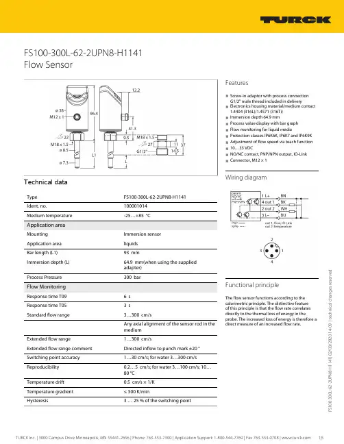
F S 100-300L -62-2U P N 8-H 1141 | 02/03/2020 14-09 | t e c h n i c a l c h a n g e s r e s e r v e dFS100-300L-62-2UPN8-H1141Flow SensorTechnical dataFS100-300L-62-2UPN8-H1141100001014Medium temperature-25…+85 °C Application areaImmersion sensor Application area liquids Bar length (L1)93 mmImmersion depth (L)64.9 mm(when using the supplied adapter) Process Pressure300 bar Flow MonitoringResponse time T096 s Response time T053 sStandard flow range3…300 cm/sAny axial alignment of the sensor rod in the mediumExtended flow range1…300 cm/sExtended flow range comment Directed inflow to punch mark ±20 °Switching point accuracy 1…30 cm/s; for water 3…300 cm/s Reproducibility 0.2…5 cm/s; for water 3…100 cm/s; 10…80 °C Temperature drift 0.5 cm/s × 1/K Temperature gradient ≤ 300 K/min3 … 25 % of the switching pointFeatures■Screw-in adaptor with process connection G1/2" male thread included in delivery■Electronics housing material/medium contact 1.4404 (316L)/1.4571 (316Ti)■Immersion depth 64.9 mm■Process value display with bar graph ■Flow monitoring for liquid media■Protection classes IP6K6K, IP6K7 and IP6K9K ■Adjustment of flow speed via teach function ■10…33 VDC■NO/NC contact, PNP/NPN output, IO-Link ■Connector, M12 × 1Wiring diagramFunctional principleThe flow sensor functions according to the calorimetric principle. The distinctive feature of this principle is that the flow rate correlates directly to the thermal loss of energy in theprobe. The increased loss of energy is therefore a direct measure of an increased flow rate.F S 100-300L -62-2U P N 8-H 1141 | 02/03/2020 14-09 | t e c h n i c a l c h a n g e s r e s e r v e d Technical dataF S 100-300L -62-2U P N 8-H 1141 | 02/03/2020 14-09 | t e c h n i c a l c h a n g e s r e s e r v e dTechnical dataMounting instructionsF S 100-300L -62-2U P N 8-H 1141 | 02/03/2020 14-09 | t e c h n i c a l c h a n g e s r e s e r v e dfrom being modified accidentally, for example.Teach functions (Quick and MAX/MIN)Quick Teach allows quick teaching in of theswitchpoint without teaching in a separate MAX/MIN range. With MAX/MIN Teach on the other hand, the flow range to be monitored is scaled to two limit values to be taught and the switchpoint is set within these two limits. Sensors with a switching output have both modes, whereas sensors without a switching output only have MAX/MIN Teach.F S 100-300L -62-2U P N 8-H 1141 | 02/03/2020 14-09 | t e c h n i c a l c h a n g e s r e s e r v e d LED displayLED Color Status DescriptionPWR Green On Operating voltage applied Device is operationalFlashingOperating voltage applied IO-Link communication active(inverted flash with T on 900 ms and T off 100 ms)FLT Red On Error displayed(for error pattern in combination with LEDs see manual)Off No errors displayed LOC Yellow On Device locked OffDevice unlockedFlashing Locking/unlocking process activeFLOWYellowOn NO: Flow switchpoint exceeded (output "high")NC: Flow below minimum switchpoint (output "high")Off NO: Flow below minimum switchpoint (output "low")NC: Flow switchpoint exceeded (output "low")FlashingTeach mode/display of diagnostic data (see manual for specification)TEMP YellowOnNO: Temperature switchpoint exceeded (output "high")NC: Temperature below minimum switchpoint (output "high")Off NO: Temperature below minimum switchpoint (output "low")NC: Temperature switchpoint exceeded (output "low")FlashingTeach mode/display of diagnostic data (see manual for specification)For detailed description of the display patterns and flashing codes, see manual D100002084IO-Link process data imageBit 1514131211109876543210Byte n 14 Bit Process Value (TEMP)State Out 2 (TEMP)State Out 1 (FLOW)Bit31302928272625242322212019181716Byte n+116 Bit Process Value (FLOW)Accessories Wiring accessoriesDimension drawingTypeIdent. no.RKC4.4T-2/TEL6625013Connection cable, female M12, straight,4-pin, cable length: 2 m, sheath material:PVC, black; cULus approval; other cable lengths and qualities available, see WKC4.4T-2/TEL 6625025Connection cable, female M12, angled,4-pin, cable length: 2 m, sheath material:PVC, black; cULus approval; other cable lengths and qualities available, see Accessories。

s Input–Resistance thermometer (2, 3, 4 wire circuit)–Thermocouples–Resistance remote signalling unit (0...5000 Ω)–Voltages, mV (–125...1200 mV)s Output–2 wire technique–4...20 mA, digital signals Electrical isolation (I/O)s 1 oder 2 independent channelss Digital low drift processing of measurement values s Customer specific linearizations Continuous sensor and self-monitoring–Parameter saved permanently in EEPROM–Monitoring of data integrety every 10 s s Substitution strategy in case of error (NE43)sApprovals for explosion protection–intrinsically safeEEx [ia] ib IIC T6, mount in zone 1II 3 G EEx n A II T6, mount in zone 2s Input functionality (absolute, differential, average value) s EMC acc. to EN 50082-2 and NE 21, CE conformables Parameterization–PC software application SMART VISION or–Parasofts 5 years warrantyTS 102 / TS 102-Ex Rail mountedtemperature transmitters,programmable,Pt 100 (RTD), thermocouples,electrical isolation10/11-8.50 ENPage 2 of 611.01OutputOutput signal (temperature linear) 4...20 mA Residual ripple (peak-to-peak)< 0.2 %Current consumption < 3.5 mA Max. output current22 mAParameterizable current error signal Underranging 3.5 mA Overranging 22 mA Manual value 3.5...22 mA Dampingt 63 = 0...30 sInputResistance (temperature linear)Resistance thermometer Pt 100, Pt 200...Pt 1000Ni 100, Ni 500min. span 20 K (15 K)Resistance 0...500 Ω/0...5000 Ωmin. span 5 Ω/50 ΩMeasuring current 300 µA Sensor short-circuit < 5 Ω (for RTD)Sensor break > 1.5 M ΩInput filter 50/60 HzThermocouples Types B, E, J, K, L, N, R, S, T, U Voltages –125 mV...125 mV –125 mV...1200 mV Min. span2 mV/50 mV Sensor monitoring current 70 nA Input filter50/60 HzInternal reference junctionPt 100, via software switchable (no jumper necessary)Power supply (at transmitter terminals/poling protected)(2 wire methode: power supply wires = signal wires))Supply voltageU s = 11.5...30 V DC for explosion protection application U i = 11.5...29.4 V DC Influence of supply voltage < 0.05 %/10 V Max. residual ripple≤ 1 % U S (< 500 Hz)Maximum loadR k Ω()Usmax Usmin –()22----------------------------------------------=Input elementMeasuring rangeMin. measuring span Standard SensorIEC 584-1Thermocouple Type B Thermocouple Type E Thermocouple Type J Thermocouple Type K Thermocouple Type R Thermocouple Type S Thermocouple Type T Thermocouple Type N 250...+1820 °C (+482...+3308 °F)–250...+1000 °C (–418...+1832 °F)–210...+1200 °C (–346...+2192 °F)–250...+1372 °C (–418...+2502 °F)–50...+1768 °C (–58...+3215 °F)–50...+1768 °C (–58...+3215 °F)–200...+400 °C (–328...+752 °F)–200...+1350 °C (–328...+2462 °F)235 °C (423 °F)30 °C ( 54 °F)37 °C ( 67 °F)54 °C (98 °F)171 °C (308 °F)193 °C (348 °F)50 °C ( 90 °F)60 °C (108 °F)DIN 43710Thermocouple Type L Thermocouple Type U–200...+900 °C (–76...+482 °F)–200...+600 °C (–328...+1112 °F)36 °C ( 65 °F)40 °C ( 72 °F)IEC 7511)2, 3 and 4 wire Resistance thermometer Pt 100Resistance thermometer Pt 1000–200...+850 °C (–328...+1562 °F)–200...+850 °C (–328...+1562 °F) 20°C ( 36 °F)15 °C ( 27 °F)DIN 437602)2, 3 and 4 wire Resistance thermometer Ni 100Resistance thermometer Ni 500–60...+250 °C (–76...+482 °F)–60...+250 °C (–76...+482 °F) 8 °C ( 15 °F)15 °C ( 27 °F)Resistance Ω0...500 Ω / 0...5000 Ω 5 Ω / 50 ΩVoltagemV–125 mV...+125 mV –125 mV...+1200 mV2 mV 50 mV1)IEC 751 a = 0.00385;2)Edison Curve No. 7General characteristicsOutput signal refreshment ratePt1000.4 s,(input signal change < 0.25 K/s) Thermocouples0.2 s,(input signal change < 2.5 K/s) Vibration resistanceVibration in operation 2 g acc. to DIN IEC 68 part 2-6 Electrical isolation (I/O) 1.5 kV AC (60 s)Long-term stability≤ 0.1 % p.a.Environment conditionsAmbient temperature range(–40)-20...85 °CTransport and storage temperature–40...100 °CRelative humidity< 100 %(100 % humidity with isolated terminals only)Condensation permittedMechanical constructionDimensions cf. dimensional drawing Weight250 gHousing material PolyamidClass of combustibility V0 acc. to UL 94Type of protection IP 20 DIN 40050)Class of protection 2 (IEC 348)Overvoltages catagory IIColor (Epoxy)light grey (RAL 9002) Electrical connectionTerminals, pluggable 2.5 mm2, screw terminalsCharacteristics at rated conditions1)(acc. to IEC 770, related to 25 °C)Measuring error incl. characteristic deviationPt 100/resistance measurement< 0.2 % or < 0.2 K/< 80 mΩWichever value is greater Thermocouple/mV< 0.2 % or < 10 µVWichever value is greater Additional influence of theinternal reference junction Pt 100 DIN IEC 751 Cl. BInfluencesInfluence effect of temperaturePt 100/resistance measurement2)ME (Ω)< (0.08 % + × 0.008 %) / 10KMS (Ω)Thermocouple/mV3)ME (mV)0.014 K< (0.08 % + × 0.01 % + × 100 %) / 10 KMS (mV)MS (K)Percentage related to measuring span MS = ME – MAMA = lower range value, ME = upper range value Explosion protectionIntrinsically safeZone 1EEx [ia] ib IIC T6EC certificate PTB No. Ex-97.D.2221 Temperature class T6/T5/T4< 50 °C/65 °C/85 °CZone 2II 3 G EEx n A II T6 Conformity declaration PTB 99 ATEX 2123 X Temperature class T6/T5/T4< 50 °C/65 °C/85 °CElectromagnetic compatibility (EMC)Pt 100: measuring range 0...100 °C, span 100 KAcc. to NAMUR NE 21 recommendationIn case of an input signal change > 0.25 K/s for Pt100 or > 2.5 K/s for thermocouples a measured value plausibility check is perfor-med.Supply circuit Output [ib]Input [ia]Max. voltage U i = 29.4 V U o = 5.6 VShort-circuit current I i = 130 mA I o = 145 mA4)Max. power P i = 0.8 W P o = 20 mWInternal inductance L i = 220 µH L o = 1 mHInternal capacitance C i = 15 nF C o = 1.55 µFType of test Degree Influence IECburst to signal/data lines2 kV< 0.5 %1000-4-4static dischargecontact discharge to:contact plateterminals for supplyterminals for sensors8 kV6 kV3.75kV< 1.0 %< 1.0 %< 1.0 %1000-4-2radiated field80 MHz...1 GHz10 V/m< 1.0 %1000-4-3coupling150 kHz - 80 MHz10 V< 1.0 %1000-4-61)Percentage related to set measuring span2)Pt 100 (0...400 °C): Effect of temperature influence< (0.08 % + 0.013 %)/10 K = 0.093 %/10 K3)Type K (0...1000 °C): Effect of temperature influence< (0.08 % + 0.01 % + 0.014 %)/10 K = 0.104 %/10 K4) Load current for connected transmitter [ia] < 1.5 mA11.01Page 3 of 6Communication/parameterizationParameterSensor type, measuring range, error signalling, general characteristics (i. e. TAG number), damping, signal simulation of outputSoftware-ToolsSMART VISION or Parasoft Software SMART VISION or Parasoft(optional)2-channel devices: programming channel 2 (terminals 41 and 42)Page 4 of 611.0111.01Page 5 of 6ABB Automation Products GmbH Borsigstrasse 2D-63755 AlzenauPhone +49(0)60 23 92 - 0Fax +49(0)60 23 92 - 33 00Subject to technical changes.Printed in the Fed. Rep. of Germany Data sheet 10/11-8.50 EN 11.01Connection diagramsDimensional diagram (dimensions in mm)。

ES300能源计量控制器手册北京华控自动化系统有限责任公司ES300简介ES300 能源计量控制器采用 12 位高精度 A/D转换器,先进的微处理器及浮点数运算方式,有效的保证了整机的信号测量精度和流量计量精度。
产品为 128×64 图形点阵液晶显示器,通过简单的设置可以实现对饱和蒸汽、过热蒸汽、液体和混合气体流量等参量的计量,并可以实现压力补偿密度,温度补偿密度,温度、压力补偿密度等。
ES300 能源计量控制器具有多种网络通信方式,仪表地址及通信波特率可通过窗口参数调整。
同一条总线上可挂接多个仪表。
ES300 能源计量控制器可直接与多种流量计配套,操作简易,功能齐全,可靠性高。
ES300 主要性能指标1、流量输入信号:传感器:差压、涡街、电磁、涡轮信号类型:0~10mA、4~20mA、脉冲(1~5,000Hz)2、压力输入信号(补偿信号):传感器:压力变送器信号类型:0~10mA、4~20mA3、温度输入信号(补偿信号):传感器:温度变送器、铂电阻(三线制)信号类型:0~10mA、4~20mA、Pt100等数据更新周期:≤0.5s4、基本误差:频率信号输入:读数的 0.1%温度信号输入:±0.5℃(-200~560℃)电压电流输入:满量程的±0.1%补偿后流量显示:满量程的±0.2%5、通信功能:具有RS485、以太网通信接口。
6、具有多种流量运算模式,可程序设定组合。
7、具有密度自动补偿功能,可程序设定组合。
8、显示功能:可显示累积流量、瞬时流量、密度、压力、温度、电流、频率、当前时间、系统信息及停电记录。
9、断电保护功能:机内的运算结果和用户设定的数据在断电时不会丢失,保存时间在十年以上。
11、供电电压:24VDC±10%12、功耗:<5W13、工作温度:-20℃~+70℃14、储藏温度:-30℃~+80℃15、相对湿度:≤90%16、外观尺寸:145mm×90mm×57mm17、重量:0.35kg工作原理安装方式本仪表采用标准 DIN35导轨,只需安装好导轨,将仪表固定在导轨上即可。


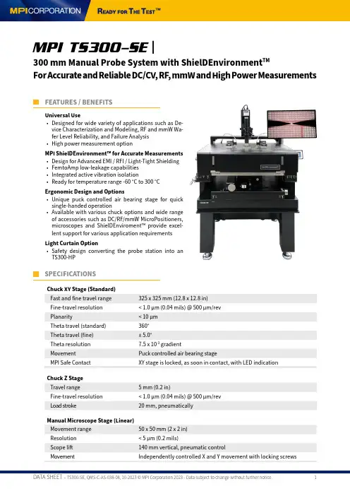
Universal Use• Designed for wide variety of applications such as De-vice Characterization and Modeling, RF and mmW Wa-fer Level Reliability, and Failure Analysis • High power measurement optionMPI ShielDEnvironment™ for Accurate Measurements • Design for Advanced EMI / RFI / Light-Tight Shielding • FemtoAmp low-leakage capabilities • Integrated active vibration isolation• Ready for temperature range -60 °C to 300 °CErgonomic Design and Options• Unique puck controlled air bearing stag e for quick single-handed operation• Available with various chuck options and wide range of accessories such as DC/RF/mmW MicroPositioners, microscopes and ShielDEnviroment™ provide excel-lent support for various application requirements Light Curtain Option• Safety desig n converting the probe station into an TS300-HPMPI TS300-SE |300 mm Manual Probe System with ShielDEnvironment TMFor Accurate and Reliable DC/CV, RF, mmW and High Power MeasurementsFEATURES / BENEFITSSPECIFICATIONSChuck XY Stage (Standard)Fast and fine travel range 325 x 325 mm (12.8 x 12.8 in)Fine-travel resolution < 1.0 µm (0.04 mils) @ 500 µm/rev Planarity< 10 µm Theta travel (standard)360°Theta travel (fine)± 5.0°Theta resolution 7.5 x 10⁻³ gradientMovement Puck controlled air bearing stageMPI Safe Contact XY stage is locked, as soon in contact, with LED indicationChuck Z Stage Travel range 5 mm (0.2 in)Fine-travel resolution < 1.0 µm (0.04 mils) @ 500 µm/rev Load stroke20 mm, pneumaticallyManual Microscope Stage (Linear)Movement range 50 x 50 mm (2 x 2 in) Resolution < 5 µm (0.2 mils)Scope lift 140 mm vertical, pneumatic controlMovementIndependently controlled X and Y movement with locking screwsSpecifications Material Nickel plated steel DimensionSee drawing Chuck to ShielDGuard height Min. 5 mmMax. No of MicroPositioners 8x DC MicroPositioners or 4x DC + 4x RF MicroPositioner Setup Platen lift control3 positions - contact (0), separation (300 µm), and loading (3 mm)MPI Probe Hover Control (PHC TM )Additional hover height (50, 100 or 150 µm) for easy probe to pad alignment Contact repeatability < 1 µm (0.04 mils) by “automated“ control RF MicroPositioner mounting Magnetic with guided rail MicroPositioner mounting Magnetic300 °C thermal isolationDepending on chuck configurationPROBE PLATENPLATEN LIFT WITH PROBE HOVER CONTROL ™MPI Probe Hover Control™ comes with hover heights (50, 100 or 150 µm) for easy and convenient probe to pad alignment.Separation Probe Hover Control™Probe in contactUniversal probe platen design for up to 8 DC MicroPositionersShielDEnvironment™MPI ShielDEnvironment™ is a high performance local environmental chamber providing excellent EMI- and light-tight shielded test environment for ultra-low noise, low capacitance measurements.MPI ShielDEnvironment™ allows up to 4-port RF or up to 8-ports DC/Kelvin or a combination of those configu-rations. MPI ShielDCap™ provides easy reconfiguration of measurement setup as well as EMI/noise shielding - which make great difference in simplifying day to day operations.ShielDEnvironment™ Electrical Specifications*EMI shielding> 30 dB (typical) @ 1 kHz to 1 MHzLight attenuation≥ 130 dBSpectral noise floor≤ -180 dBVrms/rtHz (≤ 1 MHz)System AC noise≤ 5 mVp-p (≤ 1 GHz)*Including 4 MicroPositioners.TYPICAL CONFIGURATION WITH MPI KELVIN AND MPI KELVIN-HIGH TEMPERATRUE PROBES INSIDE SHIELDENVIRONMENTTMTypical MPI configuration with Kelvin ProbesTS300-IFE WITH IceFreeEnvironment™As an alternative to the ShieDEnvironment TM , MPI IceFreeEnvironment TM provides unique capability to perform measurements with probe cards and MicroPositioners simultaneously, especially at neg ative temperatures down to -60 °C.Internal node probing with active/passive high impedance probes is very convenient.The optimized design with minimal tip drop for highest dynamic range and gamma of mmWave and Load Pullmeasurements make the system an ideal choice for RF/mmW applications on 300 mm wafers.NON-THERMAL CHUCKSStandard Wafer ChuckConnectivity Coax BNC (f)Diameter310 mm with 2 integrated AUX areasMaterial Nickel plated aluminum (flat with 0.5 mm holes) Chuck surface Planar with 0.5 mm diameter holes in centric sections Vacuum grooves sections (diameter) 4, 24, 48, 72, 96, 120, 144, 168, 192, 216, 240, 264, 288 mm SmartVacuum™ distribution In front for single DUT 5x5 mm (4 holes) and 75 mm (3 in)In center for 150, 200, 300 mm (6, 8, 12 in)Surface planarity≤± 5 µm**Rigidity< 15 µm / 10 N @edge*Single DUT testing requires higher vacuum conditions dependent upon testing application.**By using SENTIO® topographyTriaxial Wafer ChuckConnectivity Kelvin Triax (f)Diameter310 mmMaterial Nickel plated aluminum (flat with 0.5 mm holes) Chuck surface Planar with 0.5 mm diameter holes in centric sections Vacuum holes sections (diameter)4, 24, 48, 72, 96, 120, 144, 168, 192, 216, 240, 264, 288 mmSmartVacuum™ distribution In front for single DUT 5x5 mm (4 holes) and 75 mm (3 in)In center for 150, 200, 300 mm (6, 8, 12 in)Surface planarity≤± 5 µm**Rigidity< 15 µm / 10 N @edge**By using SENTIO® topographyTriaxial RF Wafer ChuckConnectivity Kelvin Triax (f)Diameter310 mm with 2 integrated AUX chucksMaterial Nickel plated aluminum (flat with 0.5 mm holes) Chuck surface Planar with 0.5 mm diameter holes in centric sections Vacuum holes sections (diameter)4, 24, 48, 72, 96, 120, 144, 168, 192, 216, 240, 264, 288 mmSmartVacuum™ distribution In front for single DUT 5x5 mm (4 holes) and 75 mm (3 in)In center for 150, 200, 300 mm (6, 8, 12 in)Surface planarity≤± 5 µm**Rigidity< 15 µm / 10 N @edge*Single DUT testing requires higher vacuum conditions dependent upon testing application.**By using SENTIO® topographyAuxiliary ChuckQuantity 2 AUX chucksPosition Integrated to front side of main chuckSubstrate size (W x L)Max. 25 x 25 mm (1 x 1 in)Material Ceramic, RF absorbing material for accurate calibration Surface planarity≤± 5 µmVacuum control Controlled independently, separate from chucksElectrical Specification (Triax)Chuck Isolation At 10 V Force-to-Guard> 5 T Ohm Guard-to-Shield> 1 T Ohm Force-to-Shield> 5 T OhmSpecifications of MPI ERS AirCool® PRIME TechnologyAmbient to20 °C to Ambient to 20 °C toElectrical isolation > 1 T Ω at 200 °C> 0.5 T Ω at 300 °C> 1 T Ω at 200 °C> 0.5 T Ω at 300 °CN/A N/ACapacitanceForce-to-Guard< 1600 pF< 1600 pF< 600 pF< 600 pF Guard-to-Shield< 2000 pF< 2000 pF < 2000 pF < 2000 pF *Typical data for all chucks based on FPS requirements.THERMAL CHUCKS> 1 T Ω at 200 °C> 0.5 T Ω at 300 °CCapacitanceForce-to-Guard< 1600 pF< 1600 pF< 1600 pF Guard-to-Shield< 2000 pF< 2000 pF < 2000 pF *Typical data for all chucks based on FPS requirements.Chuck type Ultra low noise Ultra low noise Ultra low noise Connectivity Kelvin Triax (f)Kelvin Triax (f)Kelvin Triax (f)Temperature control method Cooling air /Resistance heaterCooling air /Resistance heaterCooling air /Resistance heaterCoolant Air (user supplied)Air (user supplied)Air (user supplied) Smallest temperatureselection step0.1 °C0.1 °C0.1 °C Chuck temperaturedisplay resolution 0.01 °C0.01 °C0.01 °C External touchscreendisplay operation Yes Yes Yes Temperature stability ±0.08 °C±0.08 °C±0.08 °C Temperature accuracy 0.1 °C0.1 °C0.1 °C Control method Low noise DC/PID Low noise DC/PID Low noise DC/PID Interfaces RS232C RS232C RS232C Chuck pinhole surfaceplating: 200°C / 300°C Nickel / Gold Nickel / Gold Nickel / GoldSmartVacuum™ distribution In front for single DUT 5x5 mm (4 holes) and 75 mm (3 in)In center for 150, 200 and 300 mm (6, 8, 12 in)Temperature sensor Pt100 1/3DIN,4-line wired Pt100 1/3DIN,4-line wiredPt100 1/3DIN,4-line wiredTemperature uniformity< ±0.5 °C at ≤ 200 °C< ±1 °C at > 200 °C < ±0.5 °C at ≤ 200 °C< ±1 °C at > 200 °C< ±0.5 °C at ≤ 200 °C< ±1 °C at > 200 °CSurface flatness andbase parallelism < ±12 µm < ±12 µm < ±12 µm Max. Voltage betweenForce-to-GND600 V DC600 V DC600 V DC Force-to-Guard600 V DC600 V DC600 V DC Heating rates*25 °C-10 to 25 °C < 3 min-40 to 25 °C < 5 min-60 to 25 °C < 6 min200 °C25 to 200 °C < 18 min300 °C25 to 300 °C < 31 minCooling rates*AC3 Mode300 °C300 to 25 °C < 28 min300 to 25 °C < 28 min200 °C200 to 25 °C < 23 min200 to 25 °C < 24 min25 °C25 to -10 °C < 12 min25 to -40 °C < 20 min25 to -60 °C < 40 minTURBO Mode300 °C300 to 25 °C < 28 min300 to 25 °C < 27 min200 °C200 to 25 °C < 23 min200 to 25 °C < 23 min25 °C25 to -10 °C < 12 min25 to -40 °C < 18 min25 to -60 °C < 37 min300 °C< 50 fA < 50 fA < 50 fA CapacitanceForce-to-Guard< 600 pF< 600 pF< 600 pF Guard-to-Shield< 2000 pF< 2000 pF < 2000 pF*Typical data for all chucks based on FPS requirements.TS300-HP FOR HIGH POWER MEASUREMENTSDedicated designed for High Voltage and High Current application• On wafer high power device measurement up to 10 kV/600 A• Gold plated chuck surface for minimum contact re-sistance and vacuum holes optimized for thin wafer hand- ling down to 50 µm• Taiko wafer chuck option• Dedicated high voltage and high current probes • Anti-arcing solutionsLight CurtainLig ht Curtain Interlock protects user from accidental hig h voltag e shock by shutting down the instrument through interlock system. The interlock system at rear doors provides safety, easy and convenient initial mea-surement set-up.High Voltage Probes (HVP)Low leakag e probes specially desig ned to withstand hig h voltag e up to 10 kV (coaxial) and 3 kV (triaxial). Choice of various connectors options such as KeysightTriax/UHV, Keithley Triax/UHV, SHV or Banana.High Current Probe (HCP)High performance probes specially designed for on wa-fer measurement of hig h current up to 200 A (pulse). MPI multi-fingers high current probes are single piece consturction to efficiently handle high current and pro-vide low contact resistance.HIGH POWER PROBESHIGH POWER PROBES - SELECTION GUIDE[2]Keysight or Keithley [3]Banana: 100 A max, 1 ms max PW, 1% max PLC [4]BNC: 40 A max, 1 ms max PW, 1% Max PLCUltra High Power Probe (UHP)Desig ned for Ultra hig h voltag e and current on wafer measurement up to 10 kV/600 A (pulse). MPI replaceable multi-fingers probes tips and probe arms are design for low contact resistance for ultra-high current measure-ment and to support ultra-high voltage of up to 10 KV, without having to change probes for high voltage andcurrent application.1 finger4 fingers6 fingers8 fingers12 fingersMax current*20 A 80 A 120 A 160 A 250 A Max voltage10 KV 10 KV 10 KV 10 KV 10 KV Residual resistance (Typical)≤ 5 mΩ≤ 3 mΩ≤ 1 mΩ ≤ 1 mΩ≤ 1 mΩConnector options Banana Banana Banana Banana Banana Replaceable tip Yes Yes Yes Yes Yes Probe tip width 250 µm 250 µm 250 µm 250 µm 250 µm Probe pitch--650 µm650 µm650 µm650 µm*1 ms Max PW, 0.4% max PLCUL TRA HIGH POWER PROBES - SELECTION GUIDEUL TRA HIGH POWER PROBESHigh current probeDIMENSIONSUltra High Power probeOptional Anti-Arcing Probe CardIn addition, MPI is offering optional temperature controlof the pressurized air in a range of 20 to 200 °C, whichcorrelate direct with the chuck set temperature.High-voltage testing without arcing at higher tempera-tures are possible now.ANTI-ARCING SOLUTIONSOptional Anti-Arcing LiquidTray™Specially designed anti-arcing LiquidTray™ can be used for arcing suppressing by simply place on the high power chuck surface. Wafers can be safely placed inside the tray to submerge in the liquid for arcing free high voltage test.High Power Wafer ChucksConnectivity 110 kV Coaxial (Banana or SHV)Connectivity 2Kelvin Triax (f), 3 kV or 10 kV CoaxialDiameter310 mm with 2 integrated AUX areasMaterial Gold plated aluminum (flat with 100 µm holes)Chuck surface Planar with 0.5 mm diameter holes in centric sectionsVacuum holes sections (diameter)4, 24, 48, 72, 96, 120, 144, 168, 192, 216, 240, 264, 288 mm SmartVacuum™ distribution In front for single DUT 5x5 mm (4 holes) and 75 mm (3 in) In center for150, 200, 300 mm (6, 8, 12 in)Supported DUT sizes Single DUTs down to 5x5 mm size or wafers 100 mm (4 in) thru 300 mm(12 in)*Surface planarity≤± 5 µmRigidity< 15 µm / 10 N @edge*Single DUT testing requires higher vacuum conditions dependent upon testing application.NON-THERMAL CHUCKSElectrical Specification (Triax)Chuck isolation> 30 TΩForce to guard> 30 TΩGuard to shield> 500 GΩForce to shield> 100 GΩMPI Non-thermal Triaxial Hig h Power Chuck with g oldplated surface for low contact resistanceMPI 10 kV Triaxial Connector used for Kelvin chuck connectionHIGH POWER THERMAL CHUCKSSpecifications TC-300N Power TC-300NT Power TC-300NT ULN PowerCooling rates** (faster with -60 °C chiller)AC3 Mode25 to -10 °C< 11 min< 12 min< 18 min25 to -40 °C< 18 min< 28 min< 28 min25 to -60 °C< 36 min< 66 min< 66 min200 to 35 °C< 24 min< 35 min< 35 min200 to 20 °C< 28 min< 48 min< 48 min300 to 35 °C N/A N/A< 41 min300 to 20 °C N/A N/A< 54 min TURBO Mode25 to -10 °C< 11 min< 12 min< 18 min25 to -40 °C< 16 min< 27 min< 27 min25 to -60 °C< 34 min< 65 min< 65 min200 to 35 °C< 24 min< 35 min< 35 min200 to 20 °C< 28 min< 48 min< 48 min300 to 35 °C N/A N/A< 41 min300 to 20 °C N/A N/A< 54 minLeakage@ Voltage and:10 V 1.1 kV 10 V 3 kV 10 V 3 kV 10 kV @ -60 °C < 2 pA < 220 pA < 300 fA < 100 pA < 30 fA < 10 pA < 6 nA @ 25 °C < 1 pA < 110 pA < 150 fA < 50 pA < 15 fA < 5 pA < 6 nA @ 200 °C < 1 nA < 110 nA < 300 fA < 150 pA < 30 fA < 10 pA < 15 nA @ 300 °CN/AN/AN/AN/A< 50 fA < 15 pA < 40 nACapacitanceForce-to-Guard < 1600 pF < 600 pF < 600 pF ** Typical values, depends on chiller type and facility supply, please check MPI FPS for the certain chuck and system.System Controller / Chiller Dimensions and Power / Air Consumption System type W x D x H (mm)Weight (kg)Power cons. (VA)max. Air flow*(l/min)CDA dew PointAmbient300 x 360 x 135 121200400≤ 0 °C 20°C, -10 °C to 200 / 300 °C 300 x 360 x 135121200400≤ -30 °C -40 to 200 / 300 °C 420 x 300 x 520451200400≤ -40 °C -60 to 200 / 300 °C420 x 500 x 10201402400450≤ -40 °CElectrical primary connection 100 to 240 VAC auto switchElectrical frequency 50 Hz / 60 Hz Compressed air supply6.0 bar (0.8 MPa, 87 psi)THERMAL CHUCKS DIMENSIONSERS and MPI’s joint product AirCool® PRIME Chuck won “Electronics Industry Awards 2018” in the categ ory, “Test, Measurement and Inspection Product of the year”.ERS AirCool® Fusion*, Controller Integrated Chiller -40 °C / -60 °C ERS AirCool® Fusion*, ControllerIntegrated Chiller -10 °C*ERS electronic GmbH patented solutionTYPICAL TRANSITION TIME300 mm PRIME RF Chuck 20°C to +300°C300 mm PRIME ULN Chuck 20°C to +300°C300 mm PRIME RF Chuck -40°C to +300°C300 mm PRIME RF Chuck -60°C to +300°C300 mm PRIME ULN Chuck -10°C to +300°C300 mm PRIME ULN Chuck -60°C to +300°CThese chucks incorporate the ERS patented AC3 cooling technology and its air manage-ment system to purge the MPI ShielDEnvironment™ directly from “already used” air – re-ducing dry air consumption up to 30 to 50% as compared to other systems on the market.Copyright belongs to ERS electronic GmbH300 mm PRIME ULN Chuck -40°C to +300°CFACILITY REQUIREMENTSThermal Chuck Electrical SupplyElectrical Supply Hot only thermal chucksElectrical primary connection 100 to 240 VAC auto switchFrequency50 Hz / 60 HzCompressed Air SupplyOperating pressure 6.0 bar (0.6 MPa, 87 psi) at specified flow rateCDA dew point≤ 0 °C for hot chuck system (ambient to 300 °C)≤ -45 °C for hot and cold chuck system (-60 °C to 300 °C) General Probe SystemPower 100-240 V AC 50/60 Hz for optical accessories* only Vacuum-0.5 bar (for single DUT) / -0.3 bar (for wafers) Compressed air 6.0 ~ 7.0 bar*e.g. microscope illumination, CCD cameras, monitors.WARRANTY• Warranty*: 12 months• Extended service contract: contact MPI Corporation for more information*See MPI Corporation‘s Terms and Conditions of Sale for more details.PHYSICAL DIMENSIONSStation Platform with Bridge*Dimensions (W x D x H)1190 x 1155 x 1625 mm (46.9 x 45.5 x 64.0 in) Weight~600 kg (1322.8 lb.)*Station accessories, such as different microscopes, cameras, or laser cutters, may change the total height.MPI Global PresenceDirect contact:Asiaregion:****************************EMEAregion:******************************Americaregion:********************************MPI global presence: for your local support, please find the right contact here:/ast/support/local-support-worldwide© 2023 Copyright MPI Corporation. All rights reserved.TS300-SE with ITUN-TS300-SE and Instrument Shelf。

ES300能源计量控制器产品说明书北京华控自动化系统有限责任公司ES300简介ES300 能源计量控制器采用 16 位高精度 A/D转换器,先进的微处理器及浮点数运算方式,有效的保证了整机的信号测量精度和流量计量精度。
产品为 128×64 图形点阵液晶显示器,通过简单的设置可以实现对饱和蒸汽、过热蒸汽、液体和混合气体流量等参量的计量,并可以实现压力补偿密度,温度补偿密度,温度、压力补偿密度等。
ES300 能源计量控制器具有多种网络通信方式,仪表地址及通信波特率可通过窗口参数调整。
同一条总线上可挂接多个仪表。
ES300 能源计量控制器可直接与多种流量计配套,操作简易,功能齐全,可靠性高。
ES300 主要性能指标1、流量输入信号:传感器:差压、涡街、电磁、涡轮信号类型:0~10mA、4~20mA、脉冲(1~5,000Hz)2、压力输入信号(补偿信号):传感器:压力变送器信号类型:0~10mA、4~20mA3、温度输入信号(补偿信号):传感器:温度变送器、铂电阻(三线制)信号类型:0~10mA、4~20mA、Pt100等数据更新周期:≤0.5s4、基本误差:频率信号输入:读数的 0.1%温度信号输入:±0.5℃(-200~560℃)电压电流输入:满量程的±0.1%补偿后流量显示:满量程的±0.2%5、通信功能:具有RS485、以太网通信接口。
6、具有多种流量运算模式,可程序设定组合。
7、具有密度自动补偿功能,可程序设定组合。
8、显示功能:可显示累积流量、瞬时流量、密度、压力、温度、电流、频率、当前时间、系统信息及停电记录。
9、断电保护功能:机内的运算结果和用户设定的数据在断电时不会丢失,保存时间在十年以上。
11、供电电压:24VDC±10%12、功耗:<5W13、工作温度:-20℃~+70℃14、储藏温度:-30℃~+80℃15、相对湿度:≤90%16、外观尺寸:145mm×90mm×57mm17、重量:0.35kg工作原理安装方式本仪表采用标准 DIN35导轨,只需安装好导轨,将仪表固定在导轨上即可。
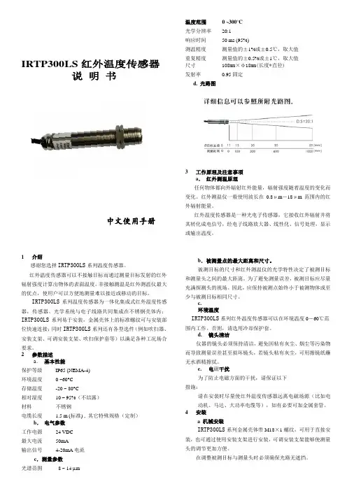
IRTP300LS 红外温度传感器说 明 书中文使用手册1介绍感谢您选择IRTP300LS 系列温度传感器。
红外温度传感器可以不接触目标而通过测量目标发射的红外辐射强度计算出物体的表面温度。
非接触测温是红外测温仪最大的优点,使用户可以方便地测量难以接近或移动的目标。
IRTP300LS 系列温度传感器为一体化集成式红外温度传感器,传感器、光学系统与电子线路共同集成在不锈钢壳体内;IRTP300LS 系列易于安装,金属壳体上的标准螺纹可与安装部位快速连接;同时IRTP300LS 系列还有各型选件(例如吹扫器、安装支架、可调安装支架、吹扫保护套等)以满足各种工况场合要求。
2 参数描述a . 基本性能保护等级 IP65 (NEMA-4) 环境温度 0 ~60°C 存储温度 -20 ~ 80°C相对湿度 10 – 95%(不结露) 材料 不锈钢电缆长度 1.5 m (标准) , 其它特殊规格(定制)b . 电气参数 工作电源 24 VDC 最大电流 50mA 输出信号 4-20mA 电流c .测量参数 光谱范围 8 ~ 14 µm温度范围 0 ~300°C 光学分辨率 20:1 响应时间 50 ms (95%)测温精度 测量值的±1%或±0.5℃,取大值 重复精度 测量值的±0.5%或±1℃,取大值 尺寸 108mm ×ф18mm(长度*直径) 发射率 0.95固定 d. 光路图3工作原理及注意事项 a . 红外测温原理任何物体都向外辐射红外能量,辐射强度随着温度的变化而变化。
红外测温仪一般使用波长在0.8μm -18μm 范围内的红外辐射能量。
红外温度传感器是一种光电子传感器,它接收红外辐射并将其转化成电信号,经电子线路放大器、线性化、信号处理,显示或输出温度。
b .被测量点的最大距离和尺寸。
被测目标的尺寸和红外测温仪的光学特性决定了被测目标和测量头之间的最大距离。
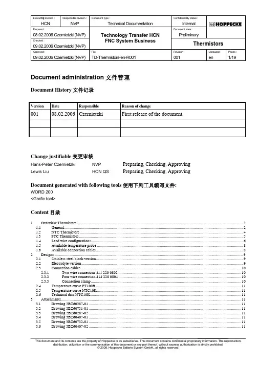
Executi ng division : Responsible division : Document type : Confidentiality status :HCN NVPTechnical Documentation InternalPrepared :Document state :08.02.2006 Czernietzki (NVP)Technology Transfer HCN PreliminaryChecked :09.02.2006 Czernietzki (NVP)FNC System BusinessThermistorsApproved :File:Revision :Language :Pages :09.02.2006 Czernietzki (NVP) TD-Thermistors-en-R001 001 en 1/19This document and its contents are the property of Hoppecke or its subsidiaries. This document contains confidential proprietary information. The reproduction,Document administration 文件管理Document History 文件记录VersionDateResponsibleReason of change001 08.02.2006 Czernietzki First release of the document.Change justifiable 变更审核Hans-Peter Czernietzki NVPPreparing , Checking , ApprovingLewis Liu HCN QS Preparing , Checking , ApprovingDocument generated with following tools 使用下列工具编写文件:WORD 200 <Grafic tool>Content 目录1 Overview Thermistors........................................................................................................................................................................2 1.1 General.....................................................................................................................................................................................2 1.2 NTC Thermistors.....................................................................................................................................................................4 1.3 PTC Thermistors......................................................................................................................................................................5 1.4 Lead wire configurations..........................................................................................................................................................6 1.5 Available temperature probe....................................................................................................................................................8 1.6 Available connection cables.....................................................................................................................................................8 2 Designs...............................................................................................................................................................................................9 2.1 Stainless steel block version.....................................................................................................................................................9 2.2 Electrolyte version...................................................................................................................................................................9 2.3 Connection cables..................................................................................................................................................................10 2.3.1 Two wire connection 414 220 0802.............................................................................................................................10 2.3.2 Four wire connection 414 220 0804............................................................................................................................10 2.3.3 Connection clamp........................................................................................................................................................10 2.4 Temperature curve PT100B...................................................................................................................................................11 2.5 Temperature curve NTC10K..................................................................................................................................................11 2.6 Technical data NTC10K.........................................................................................................................................................11 3 Attachments......................................................................................................................................................................................11 3.1 Drawing 2BZ60287-01..........................................................................................................................................................11 3.2 Drawing 3BZ60731-01..........................................................................................................................................................11 3.3 Drawing 2BZ60287-02..........................................................................................................................................................11 3.4 Drawing 3BZ60407-01..........................................................................................................................................................11 3.5 Drawing 3BZ60732-01..........................................................................................................................................................11 3.6 Drawing 3BZ60407-02. (11)1 Overview Thermistors电热调节器简介1.1 General总则Resistance elements come in many types conforming to different standards, capable of different temperature ranges, with various sizes and accuracies available. But they all function in the same manner: each has a pre-specified resistance value at a known temperature which changes in a predictable fashion. In this way, by measuring the resistance of the element, the temperature of the element can be determined from tables, calculations or instrumentation. These resistance elements are the heart of the RTD (Resistance Temperature Detector or short: Thermistor). Generally, a bare resistance element is too fragile and sensitive to be used in its raw form, so it must be protected by incorporating it into an housing.电阻元器件满足不同的标准,能够适用不同的温度范围,可满足多种尺寸和精度要求。

User GuideHeavy Duty CFM-CMM Thermo-Anemometer With built-in non-contact IR Thermometer and Laser PointerIntroductionCongratulations on your purchase of the Extech HD300 CFM Thermo-Anemometer. This handheld meter measures and displays air velocity, air flow (volume), temperature of air, and surface temperature (using the built-in non-contact IR thermometer). This meter is shipped fully tested and calibrated and, with proper use, will provide years of reliable service.FeaturesCFM/CMM Thermo-Anemometer with built-in non-contact IR Thermometer measures remote surfaces to 932°F (500°C) with a 30:1 distance to spot ratio andLaser pointer.Simultaneous display of Air Flow or Air Velocity plus ambient temperature.Eight (8) memory locations permit the user to store multiple air duct AREA values for fast and easy recall.Twenty (20) reading average for Air Flow or Air Velocity.Large backlit LCD display.3% velocity accuracy via low friction 2.83” (72mm) ball-bearing vane wheel on a3.9’ (120cm) cable.Data Hold and Max/Min/Avg.Auto Power OFF (can be disengaged).Safety•Use extreme caution when the laser pointer beam is on Array•Do not point the beam toward anyone's eye or allow the beamto strike the eye from a reflective surface•Do not use the laser near explosive gases or in otherpotentially explosive areasHD300-EU V2.0 4/082Meter Description1. LED display for Air Velocity, Air Flow, ProbeTemperature, and remote surfacetemperature. Units of measurement and useralerts are also displayed on the LCD.2. Vane Sensor. Hold the sensor in the flow ofair to take a reading.3. IR sensor: Non-contact temperaturemeasurement for remote surfaces.4. Laser Pointer: Helps the user aim the IRsensor.5. Battery access: Cover on rear panel6. PC interface jack: Use the supplied cable toconnect meter to a PC7. Upper Keypad (brief descriptions below):IRT: Press and hold to measure remote surface temperature. Release to hold the temperature value on the display.MAX/MIN (for air temperature measurements): Used to record and store the highest and lowest readings for temperature measurements made by the vaneprobe.AVG: Used to obtain Average for multi-point measurements in either FLOW or VELOCITY modes. Up to twenty (20) points can be averaged.HOLD (for air temperature measurements): Press to freeze the displayed temperature reading measured by the probe. Press again to unlock the display.Press and hold for 2 seconds to activate the LCD backlight. Press and hold againfor 2 seconds to turn the backlight off.8. Lower Keypad: Press to record and store the highest, lowest and continuous moving average readings for single point measurements. This button also functions as the decimal positioning tool in the AREA mode.mode, the meter displays air volume. In VELOCITY mode, the meter displays airspeed. This button also functions as the UP arrow button in AREA mode.AREA / NEXT: Press and hold to enter the AREA mode. The NEXT function allows the user to save AREA values to any of eight memory locations. This button is alsoused to clear stored readings in the MAX/MIN/AVG modes.Press to freeze the displayed air velocity or air flow reading. Press again to unlock display. Thisbutton also functions as the right arrow button in the AREA mode.NOTE: Battery Compartment and Tripod Mount are located on the reverse side of the meterHD300-EU V2.0 4/083HD300-EU V2.0 4/084 OperationAir Velocity Measurements1.Connect the sensor to the sensor input jack on top of the meter. 2.button. 3. Select the VELOCITY function using the UNITS button.Press the button repeatedly until the LCD displaysVEL .4. Press and hold the UNITS button for 2 seconds (untiltwo tones are heard) to change the temperature unitsfrom °C to °F or from °F to °C. The LCD will reflect theselection.5. Select the desired air velocity units using the UNITSbutton. The LCD will reflect the selection.6. Place the sensor in the air current to be measured withthe arrow on the inlet side of the vane (see diagram).7.View the air velocity and temperature readings on the LCD Display. Air Flow (Volume) Measurements (CFM / CMM)1.Connect the sensor to the sensor input jack on top of the meter. 2.3. Select the FLOW mode using the UNITS button. Press the button repeatedly until theLCD displays FLOW CFM (cubic feet per minute) or FLOW CMM (cubic meters perminute) as desired.4.Measure the dimensions of the duct or vent in question and calculate the area insquare feet or square meters Note: If the dimensional measurements are made in inches (or cm), convert them feet (ormeters) before calculating the square area.5.To begin entering the area in m 2 or ft 2press and hold the AREA button for approx. 2 seconds (until two tones are heard). 6.Momentarily press the NEXT button to select the desired memory location to store the area value (there are eight locations). 7.8.Press and hold the AREA button for approx. 2 seconds (until two tones are heard) to save the area value in memory. 9. Place the sensor in the air current to be measured with the symbol on the inlet side ofthe vane.10. View the air flow and temperature readings on the LCD Display.11. If the CFM or CMM reading exceeds 9999, the display will show the X10 or X100multiplier in the lower right hand corner of the LCD indicating that the displayed valuemust be multiplied by 10 or 100 to arrive at the correct flow measurement value.Arrow Side view of VaneHD300-EU V2.0 4/085 Non-contact IR Surface Temperature MeasurementsThe built-in IR sensor can remotely measure the temperature of just about any surface. The Laser pointer allows the user to aim accurately when taking remote measurements. 1.2.The IR sensor is located at the top of the meter. 3.Point the sensor toward the surface to be measured. 4. Press and hold the IRT button to begin measuring theIR TEMP andswitch on to help aim the meter.5. The measured IR surface temperature will appear on theLCD. The temperature displayed is the temperature ofthe area within the spot.6. When the IRT button is released, the laser pointer willswitch off and the reading will freeze (data hold) on thedisplay for approximately 7 seconds.7.After the 7 second hold time the meter returns to the AirVelocity/Flow and Air Temperature mode.WARNING: Do not directly view or direct the laser pointer at an eye. Low powervisible lasers do not normally present a hazard, but may present some potential forhazard if viewed directly for extended periods of time.Data Hold1.The HOLD button in the upper keypad area freezes the displayed vane temperature reading. Press again to unlock the display. 2. The HOLD button in the lower keypad area freezes the displayed air velocity or airflow measurements. Press again to unlock the display.3. The HOLDindicator will appear on the LCD when the display is in Data Hold mode.MIN-MAX-AVG Recording ModesThe HD300 has several MIN-MAX-AVG modes described separately below. MIN-MAX-AVG functions are available for all measurements made with the vane sensor (air velocity, air flow, and air temperature).Continuous Moving AverageIn the Continuous Moving Average mode the meter displays the continuous average of the measured readings for up to a 10 hour period.1. Turn the meter ON.2. Place the sensor in the air stream.3. Press the MAX-MIN button in the lower keypad area for air velocity / flow.4. Press the MAX-MIN button in the upper keypad area for air temperature.5. The meter will begin averaging readings once per second.Single Point Min-Max-AvgIn the Single Point Average Mode the meter takes a reading once per second andstores the highest, lowest, and average readings.1. Turn the meter ON.2. Place the sensor in the air stream.3. Press the MAX-MIN button (lower keypad area for air velocity/flow; upperkeypad area for air temperature) to enter the REC mode and display onlythe highest reading (display will show REC MAX).4. Press again to view the MIN value (display will show REC MIN). Now thedisplay will show only the lowest reading.5. Press again to view the AVG value (display will show REC AVG).6. To return to normal operation mode, press and hold the MAX-MIN buttonuntil two tones are heard.Multi-point AverageIn the Multi-Point Average Mode the meter averages up to 20 Air Velocity readings.1. Turn the meter ON.2. Press and hold the AVG button for 2 seconds (until two beeps are heard). A‘0’ will display in the upper right hand corner of the LCD and ‘AVG’ willappear on the bottom of the LCD.3. Place the sensor in the air stream under test.4. Press the AVG button momentarily to capture the reading (a single tone willbe heard) and the HOLD and AVG icons will appear on the bottom of theLCD. The ‘0’ that was displayed previously will increment to ‘1’. Thisnumber will increment with each successive press of the AVG button.5. Take more readings (up to a maximum of 20) in the same fashion asdescribed in step 4.6. The LCD will display the average of all the readings taken since the multi-point mode was accessed in step 2.7. To return to normal operation, press and hold the AVG button for 2 seconds(until two tones are heard).8. To clear the stored readings after exiting the Multi-point Average mode,press the AREA button once.HD300-EU V2.0 4/086HD300-EU V2.0 4/087 Battery ReplacementWhen the battery icon appears on the LCD, the 9V battery must be replaced.1.The battery compartment is located on the rear of the meter. 2.Press in and down on the arrow located above the tilt stand hinge. 3. Replace the 9V battery and the battery coverYou, as the end user, are legally bound (Battery ordinance) to return all usedbatteries and accumulators; disposal in the household garbage is prohibited!You can hand over your used batteries / accumulators, gratuitously, at thecollection points for our branches in your community or wherever batteries /accumulators are sold!Follow the valid legal stipulations in respect of the disposal of the device at theend of its lifecycleAuto Power OFF overrideThe HD300 is programmed to turn off automatically after idling for 15 minutes. This isdesigned to save battery life in the event the meter is left ON inadvertently. (Note: When the meter is in the “CFF/CMM” or “Average” mode, Auto Power Off is disabled.)To over-ride this feature:1.Turn the meter OFF 2.3.Release the button when appears in the display. 4.The meter will now remain ON until the user manually turns if OFF. 5. The next time the meter is turned OFF the Auto Power OFF function will be re-activated.USB PC Interface and SoftwareThe HD300 is equipped with a communication jack on its upper left side. The suppliedcommunications cable connects to this jack and to a USB port on a PC. The suppliedsoftware allows the user to view and save readings to the PC. Instructions for use andfeatures are detailed in the supplied software HELP utility.HD300-EU V2.0 4/088 IR TheoryIR thermometers measure the surface temperature of an object. The meter’s optics sense emitted, reflected, & transmitted energy that is collected and focused onto the meter’s detector. The meter’s circuitry translates this information into an LCD reading.InfraRed Measurement Considerations• When taking IR measurements the meter automatically compensates for ambient temperature changes. Note that it may take up to 30 minutes to adjust to extremelywide ambient changes.• Low temperature measurements quickly followed by high temperature measurements may require several minutes to stabilize as a result of the IR sensor cooling process. • If the surface of the object under test is covered with frost, oil, grime, etc., clean before taking measurements.• If an object's surface is highly reflective apply masking tape or flat black paint before measuring.• Steam, dust, smoke, etc. can obstruct measurements.• To find a hot spot, aim the meter outside the area of interest then scan across (in an up and down motion) until the hot spot is located.•IR measurements cannot be made through glass. IR Field of ViewEnsure that the desired target is larger than the spot size. As the distance from an object increases, the spot size of the area measured by the meter becomes larger. The meter’s field of view ratio is 30:1, meaning that if the meter is 30 inches (cm) from the target, the diameter (spot) of the object under test must be at least 1 inch (cm). Refer below to theEmissivityMost organic materials and painted or oxidized surfaces have an emissivity of 0.95.Inaccurate readings will result when measuring shiny or polished surfaces. Tocompensate, cover the surface under test with masking tape or flat black paint. Allow time for the tape to reach the same temperature as the material underneath then measure the temperature of the tape or the painted surface.Thermal Emissivity Table for Common MaterialsMaterial Emissivity Material Emissivity Asphalt 0.90 to 0.98 Cloth (black) 0.98skin 0.98 Concrete 0.94 HumanCement 0.96 Leather 0.75 to 0.80Sand 0.90 Charcoal0.96(powder) Earth 0.92 to 0.96 Lacquer 0.80 to 0.95(matt)0.97Water 0.67 LacquerIce 0.96 to 0.98 Rubber (black) 0.94Snow 0.83 Plastic 0.85 to 0.95Glass 0.85 to 1.00 Timber 0.90Ceramic 0.90 to 0.94 Paper 0.70 to 0.940.81oxides Marble 0.94 ChromiumPlaster 0.80 to 0.90 Copper Oxides 0.78Mortar 0.89 to 0.91 Iron Oxides 0.78 to 0.82Brick 0.93 to 0.96 Textiles 0.90HD300-EU V2.0 4/089HD300-EU V2.0 4/08 10Useful Equations and Conversions AREA equation for rectangular or square ductsArea equation for circular ductsCubic equationsNOTE: Measurements made in inchesmust be converted to feet or meters before using the above formulae.Unit of Measure Conversion Tablem/s ft/min knots km/h MPH 1 m/s1 196.87 1.944 3.6 2.24 1 ft/min0.00508 1 0.00987 0.01829 0.01138 1 knot0.5144 101.27 1 1.8519 1.1523 1 km/h0.2778 54.69 0.54 1 0.6222 1 MPH0.4464 87.89 0.8679 1.6071 1Width (W) Height (H) Area (A) = Width (W) x Height (H) CFM (ft 3/min) = Air Velocity (ft/min) x Area (ft 2) CMM (m 3/min) = Air Velocity (m/sec) x Area (m 2) x 60 Radius Area (A) = π x r 2 Where π = 3.14 and r 2 = radius x radiusSpecificationsGeneral SpecificationsDisplay Dual Display Multi-function LCD with 9999 countsMeasurements Air Velocity: m/s, km/h, ft/min, knots, mph;Air Flow: CMM (m3/min) and CFM (ft3/min);Air Temperature (through vane) and Surface Temperature(using the IR thermometer function): °C and °F Data Hold Freezes displayed readingSampling rate 1 reading per secondSensors Air velocity/Air flow sensor: Conventional angled vane armswith low-friction ball bearing. Air temperature sensor: Precisionthermistor (built into the vane assembly); Surface temperaturevia non-contact IR sensor.IR Distance to Spot ratio 30:1IR Spectral response 6 to 14µmIR Emissivity 0.95 fixedMIN-MAX-AVG Record and Recall lowest, highest, and average readings Auto Power OFF Automatic shut off after 15 minutes (can be disengaged) PC Interface USB PC Communication with supplied software and cable fordata acquisitionOver range indication Dashes appears on the LCDLow battery indication Battery symbol appears on the LCDPower supply 9V BatteryOperating conditions Meter: 0 to 50o C (32 to 122o F); 80% RH max.Sensor: 0 to 60o C (32 to 140o F)Dimensions / Weight Main instrument: 8.0 x 3.0 x1.9" (203 x 75 x 50mm)Sensor head: 2.8” (72mm) diameteroz.(280g)9.8WeightHD300-EU V2.0 4/0811Range SpecificationsAir Velocity Measurements Range Resolution Accuracy (%rdg) m/s (meters per second) 0.40 – 30.00 m/s 0.01 m/s ± (3% + 0.20m/s) km/h (kilometers per hour) 1.4 – 108.0 km/h 0.1 km/h ± (3% + 0.8km/h) ft/min (feet per minute) 80 – 5900 ft/min 1 ft/min ± (3% + 40ft/min) mph (miles per hour) 0.9 – 67.0 mph 0.1 mph ± (3% + 0.4m/h) knots (nautical miles per hour) 0.8 to 58.0 knots 0.1 knots ± (3% + 0.4knots)Air Flow Measurements Range Resolution Area CMM (cubic meters per minute) 0-999,900 m3/min 0.001 0 to 999.9m2CFM (cubic feet per minute) 0-999,900 ft3/min 0.001 0 to 999.9ft2 Temperature Range Resolution Accuracy0.1o C/F±2o C (4o F)Air Temperature (vane) -10 to 60o C (14 to140o F)Surface Temperature (IR) -50 to -20o C (-58 to -0.1o C/F± 5o C (9o F)4o F)0.1o C/F±2% or ±2o C (4o F)-20 to 500o C (-4 to932o F)Copyright © 2008 Extech Instruments Corporation (a FLIR company)All rights reserved including the right of reproduction in whole or in part in any form.HD300-EU V2.0 4/0812。
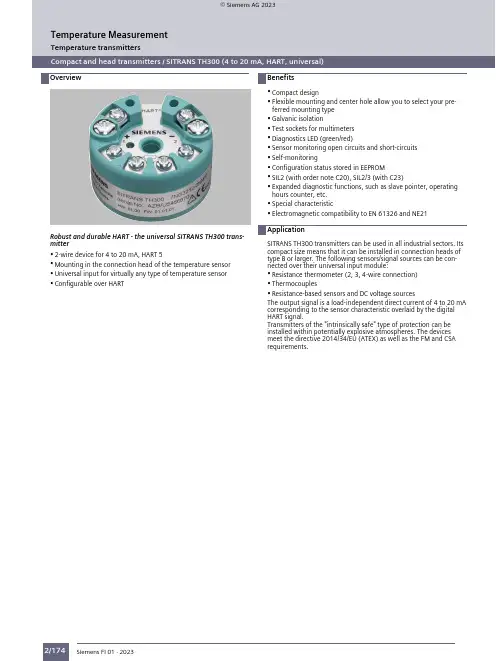
Temperature transmittersOverviewCompact and head transmitters / SITRANS TH300 (4 to 20 mA, HART, universal)Compact and head transmitters / SITRANS TH300 (4 to 20 mA, HART, universal)Robust and durable HART - the universal SITRANS TH300 transmitter•2-wire device for 4 to 20 mA, HART 5•Mounting in the connection head of the temperature sensor •Universal input for virtually any type of temperature sensor •Configurable over HART•Compact design•Flexible mounting and center hole allow you to select your preferred mounting type •Galvanic isolation•Test sockets for multimeters •Diagnostics LED (green/red)•Sensor monitoring open circuits and short-circuits •Self-monitoring•Configuration status stored in EEPROM•SIL2 (with order note C20), SIL2/3 (with C23)•Expanded diagnostic functions, such as slave pointer, operating hours counter, etc.•Special characteristic•Electromagnetic compatibility to EN 61326 and NE21SITRANS TH300 transmitters can be used in all industrial sectors. Its compact size means that it can be installed in connection heads of type B or larger. The following sensors/signal sources can be connected over their universal input module:•Resistance thermometer (2, 3, 4-wire connection)•Thermocouples•Resistance-based sensors and DC voltage sourcesThe output signal is a load-independent direct current of 4 to 20 mA corresponding to the sensor characteristic overlaid by the digital HART signal.Transmitters of the "intrinsically safe" type of protection can be installed within potentially explosive atmospheres. The devices meet the directive 2014/34/EU (ATEX) as well as the FM and CSA requirements.Temperature transmittersTemperature Measurement© Siemens AG 2023Temperature MeasurementTemperature transmittersCompact and head transmitters / SITRANS TH300 (4 to 20 mA, HART, universal)The SITRANS TH300 is configured over HART. This can be done using a handheld communicator or even more conveniently with a HART modem and the SIMATIC PDM parameterization software. The configuration data are then permanently stored in the non-volatile memory (EEPROM).Once the sensors and power supply have been correctly connected, the transmitter outputs a temperature-linear output signal and the diagnostics LED displays a green light. In the case of a sensor break, the LED flashes red, an internal device fault is indicated by a steady red light.The test socket can be used to connect an ammeter at any time for monitoring purposes and plausibility checks. The output current can be read without any interruption, or even without opening the current loop.Temperature transmittersCompact and head transmitters / SITRANS TH300 (4 to 20 mA, HART, universal)1)For customer-specific programming for RTD and TC, the start value and the end value of the required measuring span must be specified here.2)For this selection, Y01 or Y09 must also be selected.3)For this selection, Y01 must also be selected.4)Internal cold junction compensation is selected as the default for TC.5)For customer-specific programming for mV and ohm, the start value and the end value of the required measuring span and the unit must be entered here.AccessoriesFor supply units , see Catalog FI01 section "Supplementary components"Ordering example 1:7NG3212-0NN00-Z Y01+Y17+U03Y01: -10 ... +100 °C Y17: TICA123Ordering example 2:7NG3212-0NN00-Z Y01+Y23+U25Y01: -10 ... +100 °C Y23: TICA1234HEAT Factory setting:•Pt100 (IEC 751); 3-wire connection•Measuring range: 0 ... 100 °C (32 ... 212 °F)•Fault current: 22.8 mA •Sensor offset: 0 °C (0 °F)•Damping 0.0 sTemperature MeasurementTemperature MeasurementTemperature transmitters Compact and head transmitters / SITRANS TH300 (4 to 20 mA, HART, universal)Temperature MeasurementTemperature transmittersCompact and head transmitters / SITRANS TH300 (4 to 20 mA, HART, universal)Temperature MeasurementTemperature transmitters Compact and head transmitters / SITRANS TH300 (4 to 20 mA, HART, universal)Temperature MeasurementTemperature transmittersCompact and head transmitters / SITRANS TH300 (4 to 20 mA, HART, universal)Factory setting:•Pt100 (IEC 751) in the 3-wire connection•Measuring range: 0 ... 100 °C (32 ... 212 °F)•Fault current: 22.8 mA•Sensor offset: 0 °C (0 °F)•Damping 0.0 sDigital measuring errorResistance thermometerResistance-based sensorTemperature MeasurementTemperature transmittersCompact and head transmitters / SITRANS TH300 (4 to 20 mA, HART, universal)Thermocouples1)The digital accuracy in the range 100 to 300 °C (212 to 572 °F) is 3 °C (5.4 °F).2)The digital accuracy in the range 1750 to 2300 °C (3182 to 4172 °F) is 2 °C (3.6 °F).mV sensorThe digital accuracy is the accuracy after the analog/digital conversion including linearization and calculation of the measured value.An additional error is generated in the output current 4 to 20 mA as a result of the digital/analog conversion of 0.025% of the set measuring span (digital-analog error).The total error under reference conditions at the analog output is the sum from the digital error and the digital-analog error (poss. with the addition of reference junction errors in the case of thermocouple measurements).Temperature transmittersCompact and head transmitters / SITRANS TH300 (4 to 20 mA, HART, universal)(inch)Mounting on DIN railSITRANS TH300, mounting of transmitter on DIN rail59.6 (2.35)Mounting rail adapter, dimensions in mm (inch)Temperature MeasurementTemperature MeasurementTemperature transmittersCompact and head transmitters / SITRANS TH300 (4 to 20 mA, HART, universal)SITRANS TH300, sensor connection assignment。
ES300能源计量控制器产品说明书北京华控自动化系统有限责任公司ES300简介ES300 能源计量控制器采用 16 位高精度 A/D转换器,先进的微处理器及浮点数运算方式,有效的保证了整机的信号测量精度和流量计量精度。
产品为 128×64 图形点阵液晶显示器,通过简单的设置可以实现对饱和蒸汽、过热蒸汽、液体和混合气体流量等参量的计量,并可以实现压力补偿密度,温度补偿密度,温度、压力补偿密度等。
ES300 能源计量控制器具有多种网络通信方式,仪表地址及通信波特率可通过窗口参数调整。
同一条总线上可挂接多个仪表。
ES300 能源计量控制器可直接与多种流量计配套,操作简易,功能齐全,可靠性高。
ES300 主要性能指标1、流量输入信号:传感器:差压、涡街、电磁、涡轮信号类型:0~10mA、4~20mA、脉冲(1~5,000Hz)2、压力输入信号(补偿信号):传感器:压力变送器信号类型:0~10mA、4~20mA3、温度输入信号(补偿信号):传感器:温度变送器、铂电阻(三线制)信号类型:0~10mA、4~20mA、Pt100等数据更新周期:≤0.5s4、基本误差:频率信号输入:读数的 0.1%温度信号输入:±0.5℃(-200~560℃)电压电流输入:满量程的±0.1%补偿后流量显示:满量程的±0.2%5、通信功能:具有RS485、以太网通信接口。
6、具有多种流量运算模式,可程序设定组合。
7、具有密度自动补偿功能,可程序设定组合。
8、显示功能:可显示累积流量、瞬时流量、密度、压力、温度、电流、频率、当前时间、系统信息及停电记录。
9、断电保护功能:机内的运算结果和用户设定的数据在断电时不会丢失,保存时间在十年以上。
11、供电电压:24VDC±10%12、功耗:<5W13、工作温度:-20℃~+70℃14、储藏温度:-30℃~+80℃15、相对湿度:≤90%16、外观尺寸:145mm×90mm×57mm17、重量:0.35kg工作原理安装方式本仪表采用标准 DIN35导轨,只需安装好导轨,将仪表固定在导轨上即可。
贺德克HYDAC温度开关ETS3228-5-100-000产品功能贺德克HYDAC温度开关温度测量:为了采集及评定温度,提供一个连接到压力管路的温度传感器及用于油箱监测的电子温度开关。
ETS4000温度传感器,测量范围25℃...100℃,耐压可带600bar,标准输出信号位4...20mA;ETS1700系列温度开关,4点温度开关量并带1模拟量输出,4位可调整数字显示继电器,开关点及回程开关滞后值由触摸按键调整; ETS300系列温度开关,2点温度开关量并带1路模拟量输出,1点温度开关量输出,2点温度开关量输出,1点温度开关量并带1路模拟量输出,3位数字显示;HYDAC贺德克温度开关ETS3200是一款紧凑型电子产品带4位显示器的温度开关。
通过其集成的温度探头,ETS3200特别适用于直接储罐安装,有多种长度。
耐压高达600bar,集成18mm温度探头,模型可以直接安装在内联或液压块。
一个或两个不同的输出模型切换输出,可选择使用附加模拟输出信号,提供各种应用可能性。
开关点和相关可以非常快速地调整滞后轻松使用键盘。
为了最佳地适应特定环境应用,仪器有很多附加调整参数(例如。
开关延迟时间、N/C/N/O功能)。
ETS3200也有一种变体,菜单导航符合VDMA。
德国HYDAC贺德克温度开关大量现货供应,ETS32285100000(插头ZBE08 5芯)现货图参考:德国HYDAC贺德克温度开关大量现货供应;德国HYDAC贺德克电子产品:EDS300系列、EDS3000系列、EDS210系列、EDS510系列、EDS601系列、EDS1700系列、HDA3800系列、HDA3840系列、HDA4400系列、HDA4500系列、HDA4700、HDA4755系列、ETS300系列等。
贺德克HYDAC温度开关ETS386系列产品功能正品保障上海现货HYDAC贺德克温度开关;HYDAC贺德克机组可以调节太阳能设备的碗状槽,或者操作电厂中的阀门和配件。
to ETSI TETRAStandards home page (in this window)ETS/EN 300 392 seriesTETRA Voice + Data (V+D)Edition/Version & Dateclick link to downloadfrom ETSI(note green drafts willsupersede pink whenapproved)EN 300 392-1Voice+Data General Network Design V1.4.1; 2009-01 EN 300 392-2Voice+Data Air Interface (AI)Note 1: this is superseded by TS 100 392-2 V3.5.1 2011-10V3.4.1; 2010-08EN 300 392-3 Voice+Data Interworking - basic operation 392-3 is "part" number - see sub-parts below for ISIstandardEN 300 392-3-1 Interworking at the Inter-System Interface (ISI); General Design V1.3.1; 2010-08EN 300 392-3-2 Interworking at the Inter-System Interface (ISI); Additional Network FeatureIndividual Call (ANF-ISIIC)V1.4.1; 2010-08EN 300 392-3-3Interworking at the Inter-System Interface (ISI); Additional Network FeatureGroup Call (ANF-ISIGC)V1.3.1; 2011-11EN 300 392-3-4Interworking at the Inter-System Interface (ISI); Additional Network Feature ShortData Service (ANF-ISISDS)V1.3.1; 2010-08EN 300 392-3-5Interworking at the Inter-System Interface (ISI); Additional Network Feature forMobility Management (ANF-ISIMM)V1.4.1; 2010-06392-3-6, -7, -8Note - see TS 100 392-3-6, -7 & -8 for subsequent parts of ISI interworkingETS 300 392-4 Voice+Data Gateways - basic operation 392-4 is "part" number - see sub-parts below for V+D Gateway standardETS 300 392-4-1V+D Gateways - basic operation: PSTN Edition 1; Jan 99 ETS 300 392-4-2V+D Gateways - basic operation: ISDN Gateway Edition 1; Sep 00ETS 300 392-4-3V+D Gateways - basic operation: Data networks gateway (note, treat with caution -declared historical on 12/10/07 - now out of date and not maintained)Edition 1; Jun 99(historical)EN 300 392-5Peripheral Equipment Interface V2.2.1; 2010-07 ETS 300 392-6Voice+Data Line Connected Stations (Work Item deleted due to no support)n/aEN 300 392-7Voice+Data SecurityDraft V3.2.4; 2011-12V3.2.1; 2010-06 ETS 300 392-8Voice+Data Management Services (deleted in lieu of ETR 300-4)n/aEN 300 392-9General Requirements for Supplementary Services Final Draft V1.5.0; 2011-11V1.4.1; 2010-08EN 300 392-10V+D Supplementary Services (SS) Stage 1392-10 is "part" number - see sub-parts below for SS stage 1 standardEN 300 392-10-1SS Stage 1: Call identification V1.3.1; 2004-01 ETS 300 392-10-2SS Stage 1: Call report (CR)Edition 2; Aug 00 ETS 300 392-10-3SS Stage 1: Talking party identification (TPI)Edition 2; Jul 99 EN 300 392-10-4SS Stage 1: Call Forwarding (CF)V1.3.1; 2003-09 ETS 300 392-10-5SS Stage 1: List Search Call (LSC)Edition 2; Aug 00 EN 300 392-10-6SS Stage 1: Call authorized by dispatcher (CAD)V1.4.1; 2006-08 ETS 300 392-10-7SS Stage 1: Short number addressing Edition 2; Sep 99 EN 300 392-10-8SS Stage 1: Area selection (AS)V1.2.1; 2004-02 ETS 300 392-10-9SS stage 1: Access Priority Edition 2; Dec 98 EN 300 392-10-10SS Stage 1: Priority call (PC)V1.2.1; 2002-05 EN 300 392-10-11SS Stage 1: Call waiting (CW)V1.3.1; 2004-01 EN 300 392-10-12SS Stage 1: Call hold (CH)V1.3.1; 2004-02 ETS 300 392-10-13SS Stage 1: Call completion to busy subscriber Edition 2; Sep 99 EN 300 392-10-14SS Stage 1: Late entry (LE)V1.2.1; 2002-09ETS 300 392-10-15SS Stage 1: Transfer of control (note, treat with caution - declared historical on 23/2/04 -now out of date and not maintained)Edition 1; Apr 96(historical)EN 300 392-10-16SS Stage 1: Pre-emptive priority call (PPC)V1.3.1; 2006-08 EN 300 392-10-17SS Stage 1: Include call (IC)V1.2.1; 2002-05 EN 300 392-10-18SS Stage 1: Barring of outgoing calls (BOC)V1.3.1; 2003-10 EN 300 392-10-19SS Stage 1: Barring of incoming calls (BIC)V1.2.1; 2002-09 ETS 300 392-10-20SS Stage 1: Discreet listening (DL)Edition 2; May 99 EN 300 392-10-21SS Stage 1: Ambience listening (AL)V1.2.1; 2003-09 EN 300 392-10-22SS Stage 1: Dynamic group number assignment (DGNA)V1.2.1; 2002-01 ETS 300 392-10-23SS Stage 1: Call completion on no reply Edition 2; Sep 99ETS 300 392-10-24SS Stage 1: Call retention (CRT)Edition 2; Apr 00 ETS 300 392-10-25SS Stage 1: Advice of charge (withdrawn)n/aEN 300 392-11V+D Supplementary Services (SS) Stage 2392-11 is "part" number - see sub-parts below for SS stage 2 standardEN 300 392-11-1SS Stage 2: Call identification (CI)V1.2.1; 2004-01 ETS 300 392-11-2SS Stage 2: Call report (CR)Edition 1; Sep 00 ETS 300 392-11-3SS Stage 2: Talking party identification Edition 1; Jul 99 EN 300 392-11-4SS Stage 2: Call Forwarding (CF)V1.1.1; 2003-07 ETS 300 392-11-5SS Stage 2: List Search Call (LSC)Edition 1; Sep 00 EN 300 392-11-6SS Stage 2: Call authorized by dispatcher (CAD)V1.2.1; 2004-01 ETS 300 392-11-7SS Stage 2: Short number addressing (SNA)Edition 1; Apr 00 EN 300 392-11-8SS Stage 2: Area selection (AS)V1.1.1; 2000-12 ETS 300 392-11-9SS Stage 2; Access Priority (AP)Edition 1; Oct 98 EN 300 392-11-10SS Stage 2: Priority call (PC)V1.1.1; 2001-05 ETS 300 392-11-11SS Stage 2: Call waiting (CW)Edition 1; Sep 00 EN 300 392-11-12SS Stage 2: Call hold (CH)V1.1.2; 2003-05 ETS 300 392-11-13SS Stage 2: Call completion to busy subscriber (CCBS)Edition 1; Mar 00 EN 300 392-11-14SS Stage 2: Late entry (LE)V1.1.1; 2002-07 ETS 300 392-11-15SS Stage 2: Transfer of control (withdrawn)n/aEN 300 392-11-16SS Stage 2: Pre-emptive priority call (PPC)V1.2.1; 2004-09 EN 300 392-11-17SS Stage 2: Include call (IC)V1.1.2; 2002-01 EN 300 392-11-18SS Stage 2: Barring of outgoing calls (BOC)V1.1.1; 2001-08 EN 300 392-11-19SS Stage 2: Barring of incoming calls (BIC)V1.1.1; 2001-08 ETS 300 392-11-20SS Stage 2: Discreet listening (DL)Edition 1; Aug 99 EN 300 392-11-21SS Stage 2: Ambience listening V1.1.1; 2003-04 ETS 300 392-11-22SS Stage 2: Dynamic group number assignment (DGNA)Edition 1; Apr 00 ETS 300 392-11-23SS Stage 2: Call completion on no reply (CCNR)Edition 1; Apr 00 ETS 300 392-11-24SS Stage 2: Call retention (CRT)Edition 1; Sep 00 ETS 300 392-11-25SS Stage 2: Advice of charge (withdrawn)n/aEN 300 392-12V+D Supplementary Services (SS) Stage 3392-12 is "part" number - see sub-parts below for SS stage 3 standardEN 300 392-12-1SS Stage 3: Call identification (CI)V1.2.2; 2007-08 ETS 300 392-12-2SS Stage 3: Call report (CR)Edition 1; Sep 00 EN 300 392-12-3SS Stage 3: Talking party identification (TPI)V1.3.1; 2006-04EN 300 392-12-4SS Stage 3: Call Forwarding Final Draft V1.3.0; 2011-11V1.2.1; 2010-07ETS 300 392-12-5SS Stage 3: List Search Call (LSC)Edition 1; Sep 00 EN 300 392-12-6SS Stage 3; Call Authorized by Dispatcher (CAD)V1.3.1; 2006-02 ETS 300 392-12-7SS Stage 3: Short number addressing (SNA)Edition 1; Apr 00 EN 300 392-12-8SS Stage 3: Area selection (AS)V1.2.1; 2010-07 ETS 300 392-12-9SS Stage 3; Access Priority Edition 1; Oct 98 EN 300 392-12-10SS Stage 3: Priority call (PC)V1.2.1; 2004-02 ETS 300 392-12-11SS Stage 3: Call waiting (CW)Edition 1; Sep 00 EN 300 392-12-12SS Stage 3: Call hold (CH)V1.1.2; 2003-05EN 300 392-12-13SS Stage 3: Call completion to busy subscriber (CCBS)Draft Final Draft V1.2.0; 2011-11ETS 300 392-12-13Edition 1; Mar 00EN 300 392-12-14SS Stage 3: Late entry (LE)Final Draft V1.2.0; 2011-11V1.1.1; 2002-07ETS 300 392-12-15SS Stage 3: Transfer of control (withdrawn)n/aEN 300 392-12-16SS Stage 3: Pre-emptive priority call (PPC)V1.2.1; 2004-09 EN 300 392-12-17SS Stage 3: Include call (IC)V1.1.2; 2002-01 EN 300 392-12-18SS Stage 3: Barring of outgoing calls (BOC)V1.1.1; 2001-08 EN 300 392-12-19SS Stage 3: Barring of incoming calls (BIC)V1.1.1; 2001-08EN 300 392-12-20SS Stage 3: Discreet listening Final Draft V1.2.0; 2011-11ETS 300 392-12-20Edition 1; Aug 99EN 300 392-12-21SS Stage 3: Ambience listening (AL)Final Draft V1.5.0; 2011-11V1.4.1; 2011-04EN 300 392-12-22SS Stage 3: Dynamic group number assignment (DGNA)V1.3.1; 2005-04Final Draft V1.2.0; 2011-11。
ElektronischerTemperaturschalterETS 300Beschreibung:Der ETS 300 ist ein kompakter,elektronischer Temperaturschalter mitDigitalanzeige. Zur optimalen Anpassungan die jeweilige Applikation stehen zweiVarianten zur Verfügung.Der ETS 300 mit integriertemTemperatursensor bietet einenMessbereich -25 °C bis +100 °C.Er ist druckfest bis 600 bar und kann soz.B. direkt am Hydraulikblock montiertwerden.Die Variante mit separatemTemperatursensoreingang verfügt übereinen Anzeigebereich von -30 °Cbis +150 °C. Das Gerät wird vorrangigzusammen mit dem speziell für dieTankmontage entwickeltenTemperatursensor TFP 100 eingesetzt.Es ist aber auch möglich marktüblichePT 100 Temperatursensoren auszuwerten.Verschiedene Ausgangsvarianten miteinem oder zwei Schaltausgängen,optional mit zusätzlichem analogenAusgangssignal 4 .. 20 mA, eröffnen eineVielzahl von Anwendungsmöglichkeiten.Die Schaltpunkte und die dazugehörigenHysteresen können über die Folientastatursehr schnell und bedienerfreundlicheingestellt werden.Zur optimalen Anpassung an die jeweiligeApplikation bietet das Gerät vielezusätzliche Einstellparameter (z.B.Schaltverzögerungszeiten, Öffner/Schliesser-Funktion der Ausgänge).Besondere Merkmale:l Kompakter Temperaturschalter mitintergiertem oder mit separatemTemperatursensorl2 Transistor-Schaltausgänge,Ausgangsbelastbarkeit je 1,2 Al Option: Analogausgang 4 .. 20 mAl Schaltpunkt- oder Fensterfunktionl Viele hilfreiche ZusatzfunktionenETS 3X6-2Ausführung mit 1 Schaltausgang und 1 Analogausgang:Stecker 4 pol. M12x1Ausführung mit 2 Schaltausgängen und 1 Analogausgang:Stecker 5 pol. M12x1ETS 3X6-3ETS 3X8-5Sensoranschluss(Version mit separatem Sensor)1234ETS 38XGeräteeinbau-Buchse, 4-pol. M 12x1ZBE 06 (für ETS 3X6) Kupplungsdose abgewinkelt, 4-pol., M12x1ZBE 06-02 (für ETS 3X6) Kupplungsdose abgewinkelt mit 2 m Leitung, 4-pol., M12x1ZBE 06-05 (für ETS 3X6) Kupplungsdose abgewinkelt mit 5m Leitung, 4-pol., M12x1Farbkennung:braunweißblauschwarz ZBE 08-02 (für ETS 3X8)Kupplungsdose abgewinkelt mit 2mLeitung, 5-pol., M12x1ZBE 08-05 (für ETS 3X8)Kupplungsdose abgewinkelt mit 5mLeitung, 5-pol., M12x1Farbkennung:braunschwarzZBM 310Schelle zur Wandbefestigung desETS 38X(Werkstoffe: Polypropylen, AluminiumAlSi12, Stahl)Vibrationsfestigkeit:Geräteabmessungen:TFP-100 (Temp. Sensor)Schutzhülse6kt-SW276kt-SW27Kupplungsdose ZBE 03M 12x1GerätesteckerM 12x1GerätesteckerM 12x1Gerätestecker。
Thermal Conductivity InstrumentsDTC-300Site Preparation GuideTable of ContentsTable of Contents (1)Ideal Setup ................................................................................................................................... 2-3 System Components .. (3)Instrument Measurements (4)Utility Requirements (5)Power (5)Gas (6)Coolant (7)Water (8)Computer Requirements (9)Site Preparation Checklist (10)TA Instrument Offices (11)Ideal SetupIDEAL PLACEMENT AND BENCH MEASUREMENTSSelect a location with adequate floor space and a rigid laboratory bench that is level and is in a vibration-free environment.Bench length: 1.8 m (6 ft)Bench depth: 76 cm (30 in)Ideal Setup and ComponentsCOMPONENTSPlace the chiller on the same level as the instrument.A. ChillerB. InstrumentC. Computer (Controller)ABCInstrument Measurements INSTRUMENT MEASUREMENTSWidth: 64 cm (25 in)Depth: 71 cm (28 in)Height: 94 cm (37 in)Weight: 44 kg (98 lbs)POWERInstrument∙100–120 VAC, 10 A, 60 Hz (US)∙200–240 VAC, 10 A, 50/60 Hz (Non-US)∙Installation of a 16A Class B or C main fuse is recommended.Power cords providedUse power cords with plugs appropriate for your circuit.∙NEMA 5-15 plug for 100–120 VACOR∙NEMA 6-15 plug for 200–240 VACNEMA 6-15 plug NEMA 5-15 plugSupply voltages lower than indicated may result in a degradation of performance.Ensure that the mains assigned do not also supply power to noise generating equipment nearby, such as motors, welders, transformers, etc.An independent heavy GROUND wire must be provided through the power hookup. Improper grounding may cause severe damage for which the supplier will not accept responsibility. All power strips must be fully grounded and carry the ground through to the sockets into which the computer is plugged.GASPneumatic RamGas Requirements for Pneumatic Ram Type Must be nitrogen or airSource Must be from a gas cylinder, Grade 5 purityInlet Pressure Minimum: 40 psig (2.75 bar) Maximum: 50 psig (3.45 bar)Tubing ∙¼” tubing is supplied to connect f rom instrument to gas regulator∙Tubing is rated to 100 psig (7 bar)Purge GasGas Requirements for PurgeType Must be nitrogen; at sub-ambient temperatures to prevent frost and moisture buildup on internal metal componentsInlet Pressure Less than 5 psig needed–it is simply a low, steady flow to flush the furnace cavityTubing∙Purge gas port requires 1/8” tubing (provided)∙ A 1/8” stem to ¼” tubing adapter is also providedThe customer is required to supply either compressed air, dried and filtered, to 10 microns, or laboratory grade inert gas (such as nitrogen from a high pressure cylinder).COOLANTRequirementsPressure 4.3 psig (0.30 bar) maximumFlow Rate 20 L/min (5 gal/min) maximumOperating close to or below min. pressure will result inerratic operation.Cooling Capacity ∙At -20°C = 265W ∙At 0°C = 650W∙At +20°C = 1000WCoolant Liquid ∙50/50 mix of DI water and laboratory grade ethylene glycol for testing up to 300°C∙Denaturalized alcohol for sub-zero testingConnections Supplied: Two hoses (6 feet / 1.8 meters each) to connect to the Coolant Inlet and Outlet ports on the back of the furnace. The other end of each hose is blank; a male 3/8” barb with ¼” threads (provided) must be installed to connect to the coolant source.Place the chiller on the same level as the P/N 202612.001 (120V for 60Hz power) or202442.001 (240V for 50Hz power)Coolant Inlet and Outlet ports and hosesWATERExcessively cold water will result in “sweating” and corrosion of cooled metal surfaces. The purge of nitrogen gas through the furnace will prevent this.Operating below the minimum chiller coolant level will result in erratic operation. A chiller/circulator is recommended for this instrument.If a chiller/circulator is to be used, it must be placed at the same level as the instrument.Computer RequirementsHARDWARE REQUIREMENTS∙Unused RS-232 (serial) port∙Unused USB portInstrument drivers and software are provided on a CD.Computer should not be attached to other analytical instruments or LAN.SOFTWARE REQUIREMENTSItem RequirementOperatingSystem∙Windows 7 or 10, 32- or 64-bit, Ultimate, Enterprise & Professional∙Home version not supportedNetwork∙TA Instruments is not responsible for resolving issues associated withconnections to your corporate network.∙Network cards and/or certain network operation frequently interferewith the operation of the instrument and software.ConflictsTA Instruments is not responsible for resolving hardware/software conflictscreated by the addition of third party hardware or software to thecomputer.Site Preparation ChecklistThermal Conductivity Instruments: DTC-300 Sufficient bench space for instrument, computer, and chiller (if needed): ☐ Length: 1.8 m (6 ft)☐ Depth: 76 cm (30 in)Instrument power is☐ 100–120 VAC, 10 A max, 60 Hz (US)☐ 220–240 VAC, 10 A max, 50/60 Hz (Non-US)Computer, monitor, and chiller power is☐ 120 V (US)☐ 220–240 V, 6.4 A max, 50/60 Hz (Non-US)Pneumatic Ram Gas – Air or Nitrogen☐ Regulator to allow 40–50 psig (2.75–5.50 bar)Purge Gas – Dry Nitrogen☐ Under 5 psig (2.75–5.50 bar)Water Circulation☐ Nominal flow rate of 20 L/minute (5 gal/min)☐ Maximum pressure of 4.3 psig (0.30 bar)☐ Sufficient cooling capacity ☐ 50/50 mix of DI water and laboratory grade ethylene glycol (for temperatures up to 300°C)☐ Denaturalized alcohol (for sub-zero measurements) I hereby acknowledge that all utility requirements have been met per the checklist above and that they will be ready at the agreed time of installation.If all utility requirements are not met at the agreed time of installation, additional charges may be incurred for a return Service trip.CustomerDD MM YYYY CompanyCity State CountryPlease send a signed copy of the completed checklist to your local Service representative.TA Instruments Offices For information on our latest products, contact information, and more, see our website at: .To find your local TA Instruments office and contact information, visit/contact/ta-directory/TA Instruments – Waters LLCCorporate Headquarters159 Lukens DriveNew Castle, DE 19720USATelephone: 302-427-4000Fax: 302-427-4001Email: **********************。
Sistema de conexión de termopar inalámbricocompleto The Smart Connector™ (El conector inteligente)PENDIENTE DE PATENTEU E ntrada configurable por el usuario de termopar tipo J, K, T, E, R, S, B, N, CU E l software gratuito convierte su ordenador en un registrador de gráficos o un registrador de datos de múltiples canalesU C onformidad con FCC (todos los modelos)U C ompensación de junta fría y linealización incorporadasU D iseño patentado, acepta conectores y sondas de tamaño estándar y miniaturasU U n receptor funciona con múltiples conectores remotos inalámbricosU F uncionamiento con baja alimentación y modo de espera para una larga vida útil de la bateríaU C ada conector inalámbrico transmite la temperatura del termopar, la temperatura ambiental, la intensidad de señal y el estado de la batería en tiempo realU S e conecta con UWTC-REC1 para registro de gráficos y de datos en múltiples PC o el modelo UWTC-REC2 (transceptor industrial por canal único con alarma y salida analógica)Entrada de termopar Conector inalámbrico Bumper Band ®E n c h u f e s u s o n d a a u n c o n e c t o r i n t e l i g e n t e p a r a c o n s e g u i r u n s e n s o r i n t e l i g e n t e .A p r o b a d o p o r F C C /I n d u s t r y C a n a d a , A p r o b a d o p or S R R C La nueva serie de conectores para termopares inalámbricos de OMEGA incluye conectores de termopares alimentados por batería compactos e independientes que transmiten sus lecturas a un receptor anfitrión a una distancia de hasta 120 m (400'). Cada unidad puede programarse sobre el terreno para que funcione como un conector de calibración de tipo J, K, T , E, R, S, B, N o C. Cuando se activa, el conector transmite las lecturas de forma continua a intervalos preestablecidos por el usuario durante la configuración inicial. Cada unidad mide y transmite: lecturas de entrada del termopar, temperatura ambiente del conector, intensidad de señal de RF y condición de la batería al receptor y se muestra en la pantalla del PC en tiempo real con ayuda del software proporcionado. Cuando se utiliza con el receptor UWTC-REC1, pueden recibirse y mostrarse los datos de hasta 48 transmisores inalámbricos. Cada unidad incluye un software gratuito que convierte su ordenador en un registrador de banda o de datos, de modo que las lecturas quedan almacenadas y se pueden imprimir o exportar a una hoja de cálculo.Cuando se utiliza con el receptor modelo UWTC-REC2, los datos inalámbricos de un conector pueden retransmitirse desde el receptor mediante una conexión con cable comouna señal de tensión analógica, corriente o termopar para interactuar con un controlador, PLC o placa de adquisiciónde datos.AÑO DE1GARANTÍALos receptores UWTC-REC funcionan con hasta 48 transmisores UWTC y muestran/registran los datos en su PC o red. Se venden por separado.¡H a s t a 48 c a n a l e s !S o f t w a r e c e n t r a l p a r a t e r m o p ar i n c l u i d oW ESPECIFICACIONES (Visite para obtener las especificaciones completas)Entrada de UWTC: J, K, T , E, R, S, B, C o N;seleccionable con software Entrada de UWRTD: RTD de 100 Ω Pt; curva de 0,00385 o 0,00392; seleccionable con software Rango de medición: J: -100 a 760 °C (-148 a 1400 °F) K: -100 a 1260 °C (-148 a 2300 °F) T: -200 a 400 °C (-328 a 752 °F)E: -200 a 1000 °C (-328 a 1832 °F) R: 260 a 1760 °C (500 a 3200 °F) S: 260 a 1760 °C (500 a 3200 °F)B: 870 a 1820 °C (1598 a 3308 °F)C: 0 a 2315 °C (32 a 4200 °F) N: -100 a 1260 °C (-148 a 2300 °F) Pt100; 0.00385: -200 a 850 °C (-328 a 1562 °F)Pt100; 0.00392: -100 a 457 °C (-148 a 854 °F)Precisión: Tipos J y K: ±0,5% de lectura o ±1,0 °C (1,8 °F), cualquiera que sea mayor Tipos T, E, y N: ±0,5% de lectura o ±2,0 °C (3,6 °F), cualquiera que sea mayor Tipos R, S, B y C: ±0,5% escala completa Pt100: ±0,5 °C (1,0 °F)Resolución: 1 °C/1 °F Compensación de junta fría (automática): -10 a 70 °C (14 a 158 °F)Conexión del termopar: hembra universalpatentada que acepta tanto conectores de acoplamiento macho estándar (Serie OSTW) o macho miniatura (Serie SMPW)RTD: receptáculo de serie “T”, tipo T A4M; conector de acoplamiento T A4F incluido Entorno operativo: -10 a 70 °C (14 a 158 °F)Interfaz de ordenador: USB (se incluyeSe muestra el tipo K Conector miniatura (SMP)Entrada de termopar transceptores inalámbricos compatibles de la Serie UW. Los modelos UWTC vienen completos con una batería de litio “AA” de 3,6 V , soporte de montaje, termopar con cable rebordeado de tipo K y manual del operador.Los modelos UWRTD vienen completos con una batería de litio “AA” de 3,6 V , soporte de montaje, conector de acoplamiento T A4F y manual del operador. Ejemplo de pedido: UWTC-2, conector/transmisor de termopar inalámbrico con rango 120 m (400'), más anfitrión/receptor de 48 canales UWTC-REC1.Conectorestándar(OST)Los conectores inalámbricos convierten su termopar o RTD en una señal inalámbrica.Conector de acoplamiento Se incluyetermopar gratuito.Velocidad de muestreo de transmisión: transceptor de radio frecuencia (RF) programable de 1 muestra por minuto a 1 muestra cada 5 segundosSoporte: ISM 2,4 GHz; espectropropagado por secuencia directa; exento de licencia en todo el mundo(2,450 a 2,490 GHz -12 canales)Alimentación de salida de RF:UWTC-1, UWRTD-1: 0 dBm (1 mW)U WTC-2, UWRTD-2: 10 dBm (10 mW)Rango de enlace de RF:U WTC-1, UWRTD-1: hasta 60 m (200') en exteriores/línea de visión; hasta 20 m(65") en interiores/urbano U WTC-2, UWRTD-2: hasta 120 m(400') en exteriores/línea de visión; hasta 45 m (130") en interiores/urbanoPaquete de datos de RF estándar:arquitectura de comunicación abierta IEEE 802.15.4Software (incluido y gratuito):Compatible con sistema operativo Windows (2000, XP , Vista y 7)Batería interna del conector:una delitio de 3,6 V; capacidad 2,4 Ah (AA) (incluida)Vida útil de la batería (típica: a una velocidad delectura de 1 muestra/minuto a 25 °C [77 °F]): 1 año Transmisión de datos al ordenador central: lectura del termopar, lectura del ambiente del conector, intensidad de la transmisión de RF y condición de la batería Dimensiones:100 de largo x 50 de ancho x 25 de altura (sin antena) (4 x 2 x 1")Peso: 70 gramos Carcasa: plástico ABS UWTC-2Nota: debido a las normas de frecuencia de transmisión, estos productos únicamente pueden ser utilizados en Estados Unidos, Canadá, Europa y China. (Los modelos UWTC-1 y UWRTD-1 no pueden utilizarse Entrada RTD。