3M静电测试仪说明书
- 格式:pdf
- 大小:124.56 KB
- 文档页数:11
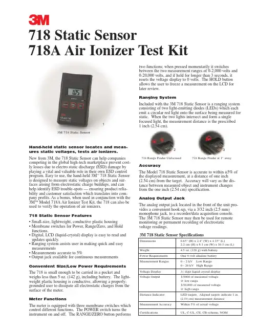
Hand-held static sensor locates and meas-ures static voltages, tests air ionizers.New from 3M,the 718 Static Sensor can help companies competing in the global high-tech marketplace prevent cost-ly losses due to electro static discharge (ESD) damage by playing a vital and valuable role in their own ESD control program. Easy to use,the hand-held 3M ™718 Static Sensor is designed to measure static voltages on objects and sur-faces arising from electrostatic charge buildups,and can help identify ESD trouble-spots — ensuring product relia-bility and customer satisfaction which translates into com-pany profits. As a bonus,when used in conjunction with the 3M TM Model 718A Air Ionizer Test Kit,the 718 can also be used to verify the operation of air ionizers.718 Static Sensor Features• Small-size,lightweight,conductive plastic housing • Membrane switches for Power,Range/Zero,and Hold functions.• Digital,LCD (liquid-crystal) display is easy to read and updates quickly.• Ranging system assists user in making quick and easy measurements• Measurements accurate to 5%• Output jack available for continuous measurements Convenient Size/Low Power Requirements The 718 is small enough to be carried in a pocket andweighs less than 5 oz. (142 g),including battery. The light-weight plastic housing is conductive,allowing a properly-grounded user to dissipate all electrostatic charges from the surface of the meter.Meter FunctionsThe meter is equipped with three membrane switches which control different functions. The POWER switch turns the instrument on and off. The RANGE/ZERO button performstwo functions; when pressed momentarily it switchesbetween the two measurement ranges of 0-2,000 volts and 0-20,000 volts,and if held for longer than 3 seconds,it resets the voltage display to 0 volts. The HOLD button allows the user to freeze a measurement on the LCD for later review.Ranging SystemIncluded with the 3M 718 Static Sensor is a ranging system consisting of two light-emitting diodes (LEDs) which each emit a circular red light onto the surface being measured for static. When the two lights intersect and form a single focused light,the measurement distance is the prescribed 1 inch (2.54 cm).AccuracyThe Model 718 Static Sensor is accurate to within ±5% of the displayed measurement,at a distance of one inch (2.54 cm) from the target. Accuracy will vary as the dis-tance between measured object and instrument changes from the one inch (2.54 cm) specification.Analog Output JackThe analog output jack located in the front of the unit pro-vides a convenient hook-up,via a 3/32 inch (2.5 mm)monophone jack,to a recorder/data acquisition console. The 3M 718 Static Sensor may then be used for remote monitoring or permanent recording of electrostatic voltage readings.3M 718 Static Sensor SpecificationsDimensions 0.85" (H) x 2.4" (W) x 4.15" (L)2.2 cm (H) x 6.1 cm (W) x 10.5 cm (L)Weight4.5 oz. (128 g) with battery Power Requirements One 9-volt alkaline battery Measurement Ranges0 – 2 kV Low Range 0 - 20 kV High Range V oltage Display 3) digit liquid crystal display V oltage Output1/1000 of measured voltage @ low range1/10,000 of measured voltage @ high rangeDistance IndicatorLED targets. Aligned targets indicate 1 in. (2.54 cm) measurement distance Measurement Accuracy Within 5% of actual voltage Certifications UL,C-UL,CE,CB-scheme,NOM3718 Static Sensor718A Air Ionizer Test Kit718 Range Finder Unfocused718 Range Finder at 1" away3M 718 Static Sensor123。
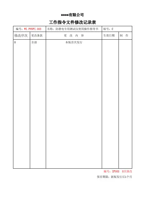
****有限公司工作指令文件修改记录表编号:SF008 0次修改保存期限:新版发行后1个月****有限公司部门工作指令文件编号 : WI.PNNPI.003页数:共 11 页版本号:第 C 版修改次数:第 0 次修改防静电专用测试仪使用操作指导书制订:审核:批准:生效日期:WI.PNNPI.003目录1. 目的2. 适用范围3. 职责4. 相关文件5 仪器使用指导5.1. 接地阻抗分析仪61-164CN的使用5.1.1设备功能简介、面板使用和其它。
5.1.2.电源插座地线测试步骤5.1.3.辅助地线测试步骤(这里指独立的防静电地线的测试).5.2 静电电压测试仪MODEL 520的使用5.2.1设备功能简介、面板使用和其它。
5.2.2静电电压测试步骤.5.3. 兆欧表MODEL 152的使用5.3.1设备功能简介、面板使用和其它。
5.3.2.表面点对点电阻测试步骤.5.3.3.表面点对地电阻测试步骤.5.3.4.体积电阻测试步骤5.4. 静电消除测试仪MODEL 156A使用。
5.4.1设备功能简介、面板使用和其它。
5.4.2. 静电消除测试仪MODEL 156A测试离子风机参数设置步骤。
5.4.3.静电消除测试仪MODEL 156A测试离子风机静电性能步骤。
5.5. 静电消除测试仪MODEL 158使用。
5.5.1设备功能简介、面板使用和其它。
5.5.2. 静电消除测试仪MODEL 158测试离子风机参数设置步骤。
5.5.3. 静电消除测试仪MODEL 158测试离子风机静电性能步骤。
5.6屏蔽袋测试仪ACL500的使用5.6.1设备功能简介、面板使用和其它5.6.2 . 屏蔽袋屏蔽性能测试步骤。
1. 目的规范接地阻抗分析仪61-164CN、静电电压测试仪MODEL 520、兆欧表MODEL 152、静电消除测试仪MODEL 156A、静电消除测试仪MODEL 1568、屏蔽袋测试仪ACL500等专用仪表的使用,以确保操作人员能正确操作相应测试设备。
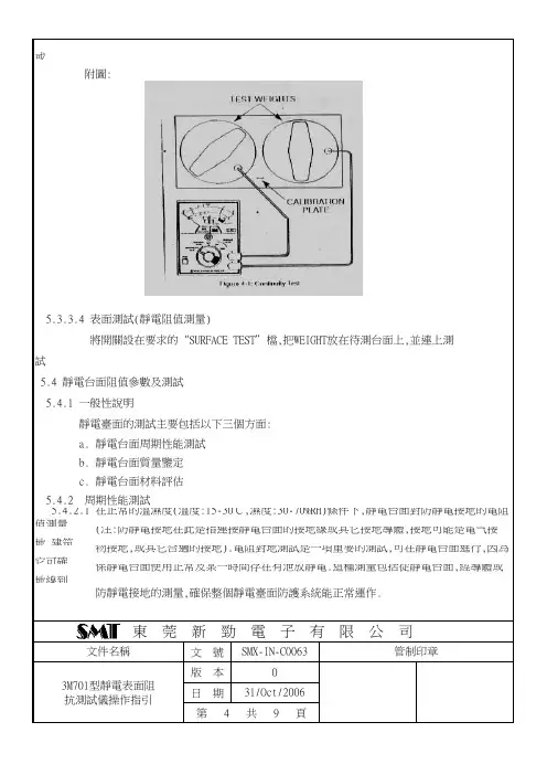
或WEIGHT需要維護或清洗. 試引線,接住“TEST”5秒,從歐姆刻度上讀取電阻值,用完后將儀表關閉;
文 號版 本日 期 b. 靜電台面質量鑒定
將開關設在要求的“SURFACE TEST”檔,把WEIGHT放在待測台面上,並連上測
5.4 靜電台面阻值參數及測試
5.4.1 一般性說明
靜電臺面的測試主要包括以下三個方面:
管制印章
5.3.3.4 表面測試(靜電阻值測量)
東 莞 新 勁 電 子 有 限 公 司
3M701型靜電表面阻
抗測試儀操作指引0第 4 共 9 頁31/Oct/2006 a. 靜電台面周期性能測試
文件名稱
SMX-IN-C0063 附圖:
c. 靜電台面材料評估
5.4.2 周期性能測試
5.4.2.1 在正常的溫濕度(溫度:15-30℃,濕度:30-70%RH)條件下,靜電台面對防靜電接地的電阻值測量 防靜電接地的測量,確保整個靜電臺面防護系統能正常運作.
(注:防靜電接地在此是指連接靜電台面的接地線或其它接地導體,接地可能是電气接地, 物接地,或其它合適的接地).電阻對地測試是一項重要的測試,可在靜電台面進行,因為它 保靜電台面使用正常及某一時間存在有泄放靜電.這種測量包括從靜電台面,經導體或地PCAR 2001年B 2002年C…月份(10月:A,11月:B,12月:C)流水號。
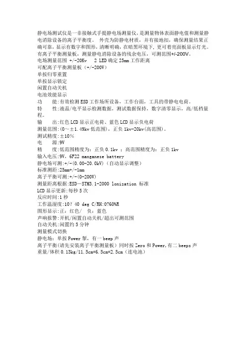
静电场测试仪是一非接触式手提静电场测量仪,是测量物体表面静电值和测量静电消除设备的离子平衡度。
外壳为防静电材质,并有接地扣,确保测量结果正确可靠,显示有数字和图形,清晰明确,在暗黑环境下, 更可着亮面板显示灯光。
有离子平衡测量板,测量静电消除设备的残余电压,可测范围+/-200V。
电场测量范围 +/-20Kv 2 LED确定25mm工作距离可配离子平衡测量板(+/-200V)单按归零重置单按显示锁定闲置自动关机电池效能显示功能:有效检测ESD工作场所设备,工作台面,工具的带静电电荷。
特性:液晶/电平显示检测数据,测试数据保持,数字清零显示,高/低档量程。
输出:红色LCD显示正电荷、蓝色LCD显示负电荷测量范围:(0~±1.49kv低范围),正负1kv-20kv(高范围)。
测试精度:±10%电源:9V精度:低范围精度为:正负0.1kv ;高范围精度为:正负1kv输入电压:9V,6F22 manganese battery静电场可测:+/-(0.00-20.0kV)(自动显示调整)标准测距:25mm+/-1mm离子平衡可测:+/-(0-200V)测量距离根据:ESD-STM3.1-2000 lonization 标准LCD显示更新:每秒5次反应时间:1秒工作温湿度:10?40 deg C/RH:0?60%R图形显示:正:红色/ 负:蓝色声响报警:开机/闲置自动关机/超出可测范围自动关机:闲置约5分钟测量模式切换静电场:单按Power掣,有一beep声离子平衡(请先安装离子平衡测量板)同时按Zero和Power,有二beeps声重量/体积0.13kg/11.5cm*6.5cm*2.5cm(连电池)(注:素材和资料部分来自网络,供参考。
请预览后才下载,期待你的好评与关注!)。

M静电测试仪 This manuscript was revised on November 28, 2020718静电测试仪使用指南安全须知3M718静电测试仪便携,可手持的设计便于测量静电电荷的电压数。
主要用于测量物体表面产生的0~20千伏静电电压。
任何其他使用行为都可能损坏仪器的能效或造成操作不安全。
3M718空气离子测试装置是与718静电测试仪配套使用装置。
主要通过中和抵消金属盘表面静电时间来检验空气离子发生器。
任何其他使用行为都可能损坏仪器的能效或造成操作不安全。
警告·718静电测试仪和718A充电器使用9V直流碱性电池。
使用任何其他电源都可能损害仪器。
·718静电测试仪和718A空气离子测试装置没有用户服务机构。
无论任何原因切勿自行拆卸仪器。
任何未经授权的行为都将终止保修协议。
·718和718A并不被设计为危险环境中使用,如任何可能有火源存在的环境。
安装与操作本仪器之前请阅读理解所有的安全须知信息1.0说明3M718静电测试仪为手携式仪器,用于定位及测量静电电荷。
他能定位ESD严重区域,是工程人员管控静电的得力助手。
本产品与3M718i空气离子发生器(另外供应)配套使用时,可校验空气离子发生器。
718静电检测仪采用电池供电有多种量测特征:使用范围:可选择测量0~2千伏或0~20千伏范围自动归零:凸起按键的设置方便归零。
无需旋钮或拨号。
HOLD功能:使得用户能够“冻结”屏显的数值,以便之后的评估。
自动关机:保护电池电量,20秒未操作即自动关机。
2.0电量需求及电池的安装2.1718和718A充电器均需要9伏碱性电池供应直流电。
2.2给两个仪器安装电池时:2.2.2卸下电池的外壳,找到内部指示相应的正负方向对准。
2.3718静电检测仪带有低电量指示标志,一旦电池电压低于大约6.5伏的时候,仪器的屏幕就会显示BAT字样。
此时,718不能输出精确的结果,应更换新电池。
文件制修订记录
1.0目的
确保使用时得到正确数据,保证使用者有一致操作方法。
2.0范围
适用本厂用来检测使用的FMX-003静电测试仪。
3.0操作使用规范内容
3.1使用之前首先要确认静电测试仪是否在校正期限内;超出期限不可使用,必需送校正合格后方可使用。
3.2首先将静电测试仪的导线夹夹到静电线上,并确认接触牢固。
3.3取出静电测试仪顶部的平行板,单击机器上的POWER键打开静电测试仪,显示屏上方带(+)(-)的符号表示正负极,在测被测物的时候该物体是带正电的时候就在(+)的方格里面显示,在测被测物的时候该物体是带负电的时候就在(-)的方格里面显示。
3.4静电测试仪开启的时候其正前方的两个LED灯同时也会亮,这两个灯就是控制机体与被测物体的距离,他们的最佳距离是25毫米(也就是前方两个LED灯聚焦为一个点的距离)。
3.5根据被测物体电压不同则可以用单位转换键(IB)来转换单位,如果需要保持最大读数的时候单击HOLD键就可以保持,显示屏上会出现HOLD字样;如取消保持,则再单击HOLD键,显示屏上的HOLD字样会消失.如要归零则单击ZERO键。
3.6该机有一个特点在打开机子8分钟的时候它有一个节约电池的模式会自动关机.如果你不需要他在一定时间内关机的时候,就要在开机的时候按住开关键POWER3秒钟显示屏里面出现A.OFF就可以了。
4.0使用静电测试仪时按照被测静电的要求去按各按键的功能,读出显示数值。
5.0测试完毕后,关掉静电测试仪电源开关,静电测试仪为精密测量仪器,各按键不可随意乱按,不可撞击及跌落。
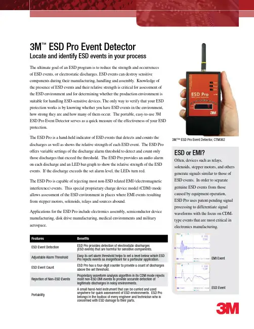
3M ™ ESD Pro Event DetectorLocate and identify ESD events in your processThe ultimate goal of an ESD program is to reduce the strength and occurrences of ESD events, or electrostatic discharges. ESD events can destroy sensitive components during their manufacturing, handling and assembly. Knowledge of the presence of ESD events and their relative strength is critical for assessment of the ESD environment and for determining whether the production environment is suitable for handling ESD-sensitive devices. The only way to verify that your ESD protection works is by knowing whether you have ESD events in the environment, how strong they are and how many of them occur. The portable, easy-to-use 3M ESD Pro Event Detector serves as a quick measure of the effectiveness of your ESD protection.The ESD Pro is a hand-held indicator of ESD events that detects and counts the discharges as well as shows the relative strength of each ESD event. The ESD Pro offers variable settings of the discharge alarm threshold to detect and count only those discharges that exceed the threshold. The ESD Pro provides an audio alarm on each discharge and an LED bar-graph to show the relative strength of the ESD events. If the discharge exceeds the set alarm level, the LEDs turn red.The ESD Pro is capable of rejecting most non-ESD related EMI (electromagnetic interference) events. This special proprietary charge device model (CDM) mode allows assessment of the ESD environment in places where EMI events resulting from stepper motors, solenoids, relays and sources abound.Applications for the ESD Pro include electronics assembly, semiconductor device manufacturing, disk drive manufacturing, medical environments and military aerospace.33M™ ESD Pro Event Detector, CTM082Features BenefitsESD Event Detection ESD Pro provides detection of electrostatic discharges (ESD events) that are harmful for sensitive components.Adjustable Alarm Threshold Easy-to-set alarm threshold helps to set a level below which ESD Pro rejects events as insignificant for a particular application.ESD Event CountESD Pro has a four-digit counter to provide a count of discharges above the set threshold.Rejection of Non-ESD EventsProprietary waveform analysis algorithm in its CDM mode rejects most non-ESD EMI events to provide accurate detection of legitimate discharges in noisy environments.PortabilityA small hand-held instrument that can be carried and used anywhere for quick assessment of ESD environments. ESD Pro belongs in the toolbox of every engineer and technician who is concerned with ESD damage to their parts.ESD or EMI?Often, devices such as relays, solenoids, stepper motors, and others generate signals similar to those of ESD events. In order to separate genuine ESD events from those caused by equipment operation, ESD Pro uses patent-pending signal processing to differentiate signal waveforms with the focus on CDM-type events that are most critical in electronics manufacturing.EMI EventESD EventImportant NoticeAll statements, technical information, and recommendations related to 3M’s products are based on information believed to be reliable, but the accuracy or completeness is not guaranteed. Before using this product, you must evaluate it and determine if it is suitable for your intended application. You assume all risks and liability associated with such use. Any statements related to the product which are not contained in 3M’s current publications, or any contrary statements contained on your purchase order shall have no force or effect unless expressly agreed upon, in writing, by an authorized officer of 3M.Warranty; Limited Remedy; Limited Liability.This product will be free from defects in material and manufacture for a period of one year from the time of purchase. 3M MAKES NO OTHERWARRANTIES INCLUDING, BUT NOT LIMITED TO, ANY IMPLIED WARRANTY OF MERCHANTABILITY OR FITNESS FOR A PARTICULAR PURPOSE . If this product is defective within the warranty period stated above, your exclusive remedy shall be, at 3M’s option, to replace or repair the 3M product or refund the purchase price of the 3M product. Except where prohibited by law, 3M will not be liable for any indirect, special, incidental or consequential loss or damage arising from this 3M product, regardless of the legal theory asserted.Please recycle. Printed in USA.© 3M 2008. All rights reserved.98-0799-0786-53Electronic Solutions Division Static Control Products6801 River Place Blvd.Austin, TX 78726-9000Ordering information: 1-866-722-3736Technical support: 831-459-7488FAX 800//static3M is a trademark of 3M Company.Where to Use the 3M ™ ESD Pro?ESD Pro is a versatile instrument with several important applications, among which are:• E SD Diagnostics and TroubleshootingWhenever an ESD issue comes up, ESD Pro is your best tool to identify the location of the problem occurrence. Find the specific steps in your process that cause ESD events, and the relative strength of an ESD event at each step. It also can be used to verify whether the problem still remains or it has been corrected.• E valuation of ESD-protective EquipmentDoes your ionizer really improve your ESD situation in a particular location? Simply run your process with your ionizer on and then off and ESD Pro will show you whether this ionizer makes a difference in your process. With ESD Pro you will be able to select and to install your ESD protective measures with the maximum efficiency.• T ool QualificationCan you process your sensitive components on a particular tool? Find it out with ESD Pro before damaging your devices.• N ext StepFor more advanced ESD diagnostics and qualification, use 3M™ EM Aware ESD Monitors that can provide you with the actual discharge strength values and enable you to have a record of your ESD environment in several locations simultaneously.Functional Sensitivity 1..1000V Threshold Adjustable Discharge Polarity Both Event Count 4-digit counter Event Magnitude LED Bar ESD Event Indication LED bar, buzzerEMI Event Rejection CDM mode select;all events select Power9V alkaline batteryOrdering InformationESD Pro is shipped with Antenna CTA110, Battery 9V Alkaline, User’s Guide and Storage Case. Please contact the factory for other options and accessories.Mechanical Dimensions (approx.)without antenna 4.73”H x 2.56”W x 0.9”D 120 mm x 65 mm x 23 mm with antenna6.82”H x 2.56”W x 0.9”D 173 mm x 65 mm x 23 mmAll specifications are subject to change without notice.。

718 静电测试仪使用指南安全须知3M 718静电测试仪便携,可手持的设计便于测量静电电荷的电压数。
主要用于测量物体表面产生的0~20千伏静电电压。
任何其他使用行为都可能损坏仪器的能效或造3M警告·718·718·7181.03M 718静电测试仪为手携式仪器,用于定位及测量静电电荷。
他能定位ESD严重区域,是工程人员管控静电的得力助手。
本产品与3M 718i空气离子发生器(另外供应)配套使用时,可校验空气离子发生器。
718静电检测仪采用电池供电有多种量测特征:使用范围:可选择测量0~2千伏或0~20千伏范围自动归零:凸起按键的设置方便归零。
无需旋钮或拨号。
HOLD功能:使得用户能够“冻结”屏显的数值,以便之后的评估。
自动关机:保护电池电量,20秒未操作即自动关机。
2.0 电量需求及电池的安装2.1 718和718A充电器均需要9伏碱性电池供应直流电。
2.2 给两个仪器安装电池时:2.2.22.3718静电检测仪是精密电子设备。
使用不当或粗暴对待会损坏仪器并使其无法提供精确的量测数据3.1 开启仪器和关闭仪器:开启718静电检测仪,需按POWER键片刻。
通过LCD屏显以及前方红色二极管灯是否亮起确认是否已开机。
关闭仪器需按POWER键片刻,通过LCD屏显确认是否已关机3.2产生静电电压量测:手持测量仪距受测物1英寸距离。
屏显会随着量测电压以千伏为单位更新。
若量测电压超出量测范围,屏显将显示-1字样。
此时,请将范围设置更大。
假如设置为最大范围0~20千伏之后仍超过范围,则718静电检测仪无法测量该物品的静电电压。
3.3键状态。
状态下LED3.53.6测量精度仪器正面有2个LED指示灯。
将这两个会发出红光的灯对准被测物表面,让两个红光聚在同一点。
当将仪器渐渐靠近被测物时,红光会渐渐聚合,当红光聚合在一点时,就是距离大约为1英寸的时刻,此时便可测量。
为得到更精确的测量,建议用户人工测量仪器外壳与待测物的距离。
一、仪表介绍
电源开关 定位光圈输出端
二、使用方法
1、打开测试仪的电源开关,LCD上显示一个零点几千伏的读数;
2、打开电源开关的同时,仪器的前端会发出两个光圈,如图1;
3、前后移动仪器,将光圈重合在待测物体的表面,这时仪表的读数就是被测物的表面静电压。
如图2。
静电场强度测试仪12
1
2
图1图2
三、离子风机新购设备的验收及使用中的定期检测方法
新购设备测试:
偏移电压(offset voltage):在置于离子化环境中的CPM的充电平板上观测到的残留电压,小于±35V为合格。
衰减时间(decay time):在置于离子化环境中的CPM的充电平板上的电压由±1000V变化到±100所用的时间,td≤10s为合格。
使用当中的离子化设备用以下方法每季度检测一次其有效性:
A、准备好OHP纸,使用OHP纸摩擦OHP纸,摩擦使之带电,对带电的OHP纸进行电位测试,希望带电量在 ±0.5 KV 以上。
B、将带电的OHP纸,放在离子风机有效范围内,放置2-3秒钟,再对进行OHP电位测试,电压
静电压测试仪
下降到100V以内为合格。
离子风机
离子风
OHP纸
C、使用SIMCO FMX003多功能静电电压测量仪,安装专用充离子平衡测量板后,置于离子化设备作用的工作区(离子风机一般距离为30~100CM)开机状态下记录其电压值,该指标每季度测量一次。
测量结果记录在《静电消除设备--定期检测记录表》中
压,。
****有限公司工作指令文件修改记录表编号:SF008 0次修改保存期限:新版发行后1个月****有限公司部门工作指令文件编号 : WI.PNNPI.003页数:共 11 页版本号:第 C 版修改次数:第 0 次修改防静电专用测试仪使用操作指导书制订:审核:批准:生效日期:WI.PNNPI.003目录1. 目的2. 适用范围3. 职责4. 相关文件5 仪器使用指导5.1. 接地阻抗分析仪61-164CN的使用5.1.1设备功能简介、面板使用和其它。
5.1.2.电源插座地线测试步骤5.1.3.辅助地线测试步骤(这里指独立的防静电地线的测试).5.2 静电电压测试仪MODEL 520的使用5.2.1设备功能简介、面板使用和其它。
5.2.2静电电压测试步骤.5.3. 兆欧表MODEL 152的使用5.3.1设备功能简介、面板使用和其它。
5.3.2.表面点对点电阻测试步骤.5.3.3.表面点对地电阻测试步骤.5.3.4.体积电阻测试步骤5.4. 静电消除测试仪MODEL 156A使用。
5.4.1设备功能简介、面板使用和其它。
5.4.2. 静电消除测试仪MODEL 156A测试离子风机参数设置步骤。
5.4.3.静电消除测试仪MODEL 156A测试离子风机静电性能步骤。
5.5. 静电消除测试仪MODEL 158使用。
5.5.1设备功能简介、面板使用和其它。
5.5.2. 静电消除测试仪MODEL 158测试离子风机参数设置步骤。
5.5.3. 静电消除测试仪MODEL 158测试离子风机静电性能步骤。
5.6屏蔽袋测试仪ACL500的使用5.6.1设备功能简介、面板使用和其它5.6.2 . 屏蔽袋屏蔽性能测试步骤。
1. 目的规范接地阻抗分析仪61-164CN、静电电压测试仪MODEL 520、兆欧表MODEL 152、静电消除测试仪MODEL 156A、静电消除测试仪MODEL 1568、屏蔽袋测试仪ACL500等专用仪表的使用,以确保操作人员能正确操作相应测试设备。
3M CTM048 静电放电探测仪
3M CTM048静电放电探测仪EM EYE 和EM AWARE TNG
EM EYE METER:
▪监测HBM,MM和CDM模式下产生的静电放电电压
▪可测EMI干扰信号;
▪可将EMI信号屏蔽掉,测试出ESD放电电压值.
优点:
▪轻便,方便携带;
▪使用简单:触摸屏幕,ESD放电电压直接显示于屏幕上;
▪精准的定位测试和查找,探测出操作过程中发生的ESD放电;可屏蔽掉干扰信号,测出真实的ESD值;
▪数据直接存储到SD卡中,并可以导出EXCEL表格供保存和分析.
EM AWARE TNG
•在线实时监测ESD DISCHARGE放电电压值;
•在线实时监测STATIC VOLTAGE静电电压值;
•当ESD放电电电压值和静电电压值超出设定阀值,设备发出警报;
•屏弊EMI干扰信号,探测出真实的ESD EVENT放电。
• LCD DISPLAY 显示监测数据;
静电放电探测仪器选择指南。
3740 Wrist strap +shoe testerOperating Instructions MO 0688-0201February, 2001II. Declaration of ConformityThe 740 Wrist Strap and Shoe Tester is in conformity with the regulations of the EMC-directive 89/336/EWG. The following standards have been taken into account while designing and manufacturing the instrument: EN 60204-1/85,EN 60204-1/91, EN 61010 (Safety),EN 50082-1/92 and EN 50082-2/92.I. GeneralPersonnel grounding devices such as wrist straps and conductive footwear are the primary method to minimise charge generation on the human body. They must be able to drain this charge as rapidly as it is generated.For this reason, it is important to test wrist straps and conductive footwear on a regular basis to ensure they are functioning properly and that the test results can be recordedGround cord 4 mm studContact plate for wrist strap teste.g. - data transfer to PC, electrical door opening system, acoustic signal, etc.selection for wrist strap and shoe testshoe electrode On / Off switchRmax III. DescriptionThe 740 wrist strap and shoe tester is an electronic test instrument which is easy to operate and designed to be wall mounted. An AC/DC -transformer is supplied. The 740 switches off automatically after non-use for approximately 30minutes.The unit consists of two measurement circuits with an open circuit test voltage of 20 V for wrist strap and shoe test applications. For wrist strap and footwear testing, a minimum thresholdresistance of 750 k Ω is set internally. The desired maximum allowable resistance level can be selected separately for each measurement. If the resistance of the tested wrist strap or footwear is within the selected range, the green "o.k."-LED will illuminate. The red "<" -LED alerts theoperator that the resistance of the tested device isunder 750 k Ω. The red ">"-LED indicates that theselected maximum resistance is exceeded.The 740 can be connected to external devices such as computers (for data recording), electrical door opening systems, counter or other evaluating components.The 740 wrist strap and shoe testerconsists of:-3.5" - diskette containing instruction manual and 740 daily log sheet - Base unit-Data output connector plug-Wall mounting kit, 3M Dual Lock ™ fastening system and template-Cover for wrist strap plug-in jack -AC/DC - transformer -Ground cordAccessories:-Shoe electrodes type 741 (single electrode) or 741D (dual electrode) (to be ordered separately).IV. OperationConnect the AC/DC - transformer (DC 24-30 V,150 mA) to the 740 tester.Note: If you notice a delay in the response time of the LED illumination please connect the ground cord supplied to the ground socket of the 740.Please ensure proper earth ground connection!Switch the unit on. All LEDs will flash forapproximately 1 s to check their function. Selectthe desired upper maximum resistance level forboth the wrist strap and shoe test by using a smallscrew driver.The 741/741D shoe electrode must be connected if footwear testing is required.V. Wall MountingThe enclosed 3M Dual Lock™ fastening discsmust be screwed to the wall using the attachedtemplate approximately 1500 mm (5 feet) abovethe floor. Drill three holes of 5mm (0.2 in)diameter at marked locations. Make sure the areaon the 740 in which the Dual Lock™ fasteningstrips are placed is free of dust and dirt. Attach the3M Dual Lock™ fastening strips to the rear of the740 tester to the bottom and top in parallel; seedrawing for locations.For securing on the wall, press the 740 firmlyagainst the discs. For removal of the 740, lift thetop corners with both hands.VI. Wrist Strap TestPut the wrist band on with ground cord attachedand insert the ground cord into the wrist strapplug-in jack. Depress the metal contact plate andhold it. One of the indicator-LEDs will illuminate.An illuminated green LED indicates that the wriststrap performs within the resistance range of750kΩ to the upper selected value of 2, 5, 10 or35 MΩ. If a red "<"-LED is on, the currentlimiting resistor in the ground cord is bypassedand the cord has to be replaced. The red ">"-LEDindicates that the selected resistance range isexceeded. Check to see if the high resistance is inthe cord, the wrist band or in the contact betweenwrist band and the operator’s skin. To check theresistance of the ground cord, leave the plug endof the ground cord attached to the tester anddisconnect the snap end from the wrist band.Connect ground cord snap to the stud in the handsymbol or press it onto the contact plate anddepress the plate until one of the LEDs isilluminated.TemplateIf the green LED illuminatesnow, the ground cord can beused.If the red ">"-LED is lit,replace the ground cord.In some cases, high contact resistance between theskin and wrist band will cause the tester to show ared ">" - LED condition. This resistance may becaused by dry skin or the presence of hair in thewrist area. The use of a skin lotion isrecommended to solve this problem.If a red ">"- LED condition still exists, replace thewrist band.VII. Shoe testEither the 741/741D shoe electrode must be connected to the 740 shoe jack.a) when the 741 single shoe electrode is used:If the red ">"-LED is illuminated, clean the soles of the shoes or check shoe grounding system (heel ground or toe ground strap) and retest. If, after cleaning, the red ">"-LED remains lit, replace it by an appropriate device. If the red "<"-LED is illuminated, the minimum resistance of the shoes or shoe grounding system is under 750 k Ω.An electrical hazard to personnel may exist at the work place.b) when the 741D dual shoe electrode is used:The dual shoe electrode allows differentiation between the right and left shoe; giving the right shoe a preference in indication. This means, if both shoes or just the right one are out of range,you will get identical indications as it would be with the single shoe electrode. If just the left shoe is out of range, the corresponding red LED will flash. Consequently, in case of a steadily lit red LED, you shall clean or remove right shoe first and retest. If the right shoe is in the "ok"-range then, you will obtain information aboutperformance of the left shoe and you can react accordingly.The shoe test does not influence the wrist strap test, therefore the shoes can be tested while the wrist strap is still connected to the 740 or the wrist strap can be tested while the operator is standing on the 741 shoe electrode. Both metal plates shall not be pressed at the same time.Switch the 740 on. Stand on the applied shoe electrode. If you are using shoe straps with a 1M Ω - resistor on both feet to be tested with the 741 shoe electrode, you have to test the straps one after the other, to avoid a red "too low" -indication. Care must be taken not to put the non-tested foot on ESD - protective flooring to avoid a bypass to ground. Depress the metal contact plate for shoe test until one of the indicator - LEDs lights up. The green LED indicates that theresistance of the person through the footwear is in the range between 750 k Ω and the desired upper maximum level (10, 35, 50 or 100 M Ω).VIII. Data Output ConnectorIf you are going to use the data output connector you must follow a test sequence. It must be wrist strap test first and then the shoe test. If this sequence is not strictly kept, the output at the pins described on page 7 will be mixed up .The 740 will provide digital signals (high/low) while testing the personnel grounding devices. These digital signals can be used for data recording (Example 1) and authorisation control equipment such as electrical door opening systems (Example 2). The output of the 740 will give you permanently +5 V at pin 3 and DC-return at pin 6. The remaining pins 1, 2, 4 and 5 (open collector) will be high(max.+30 V/20 mA have to be provided externally) or low (DC-return) while pressing on the contact plates either for wrist strap or shoe tests. The chart on page 7 shows all of the possible test results and the corresponding output levels.Example 1: Output connection for use with a computer Example 2: Output connection for use with a controlling deviceComputer input Computer groundData output connector pin status when testing wrist strap/shoeThe sequence for testing must be wrist strap test first and then the shoe test.Shaded pin indicators will read "hi" if the sequence is reversed or only the shoe tests are performed.Data Output Connectorpin 1, 2, 4, 5-high or low pin 3-+5 V pin 6-DC-returnIX. SpecificationsDimension of base unit :138 mm x 190 mm x 53 mm (5.25 x 7.5 x 2) inches Weight :450 g (15.75 oz)Power supply :external AC/DC - transformer,DC 24-30 V/150 mAAccuracy :± 10% of 2, 5, 10, 35 and 50 M Ω-ranges ± 20% of 100 M Ω-range Output :open collector at pin 1,2, 4, 5(max. +30 V/20 mA)DC-return at pin 6, +5 V at pin 3Measurement voltage :DC (20±1) V (open circuit)750 k ΩᕡᕣᕢX. Calibration ProcedureThe following procedure can be used to determine if the 740 operates within its specifications.Please note: The tester has no adjustable components.Equipment needed:1.Resistors750 k Ω - 120 M Ω, tolerance ± 1%2. 2 leadsas required to connect the reference resistora) calibration of wrist strap test circuit:Connect the reference resistor to the 740 as shown in the figure below. Switch the 740 unit on. Select the 2 M Ω-range and use the reference resistors as indicated in the test table and press contact plate A.b) calibration of shoe test circuits:The 740 Tester can either operate with the single or dual shoe electrode. They are identified by the wiring in the 3-pin plug according to DIN 41 524,type HIRSCHMANN MAS 3100, that connects the shoe electrode to the 740. For the single shoe electrode, the cord is connected to pin 1 while pins 2 and 3 are shunted and grounded.The dual shoe electrode uses the same plug but has got the following connections:pin 1: right shoe electrode pin 2: openpin 3: left shoe electrode.Reference Resistance LED -resistor range settings Indication *750 k Ω 2 M Ω - rangeRed 900 k ΩGreen 1.8 M ΩGreen >2.2 M ΩRed 4.5 M Ω 5 M Ω - range Green >5.5 M ΩRed 9.0 M Ω10 M Ω - range Green >11.0 M ΩRed 31.5 M Ω35 M Ω - rangeGreen >38.5 M ΩRed*This example is used aboveThe LEDs will indicate as shown below if the 740performs within specifications. Repeat this procedure for 5, 10 and 35 M Ω-ranges.11.1 MΩII) calibration of the dual shoe test circuits: The 740 Tester measures the resistance of both shoes almost at the same time. The test result for the circuit of the right shoe has got priority. The calibration can be either performed with two reference resistors for both circuits to be checked at the same time or -corresponding to the single shoe test - with one reference resistor for one circuit to be checked and an appropriate bridge resistor (1MΩ e.g.) for the other circuit. For completion of calibration, the test has to be repeated with connections of the resistors vice versa. Follow the instructions for the single electrode calibration test accordingly.For the operation with two reference resistors proceed as follows: Connect one reference resistor between contact 1 of the socket and the stud and the other one between contacts 2 and 3. Select the 10 MΩ-range and set the reference resistors as indicated in the test table and press contactplate B. The LEDs shall light as shown below. Repeat this procedure for 35, 50 and 100 MΩ-ranges.Right shoe Left shoeelectrode electrodecircuit circuit SignalOK OK green steadily high OK>red steadilylow OK<red steadilyOK high>red flashingOK low<red flashing high low>red steadilylow high<red steadily high high>red steadilylow low<red steadilyI) calibration of the single shoe test circuit: Connect a reference resistor to the 740 between contact 1 of the socket and the stud as shown below. Contacts 2 and 3 of the socket shall be bridged via an appropriate resistor (1MΩ e.g.) Select the 10 MΩ-range and set the reference resistors as indicated in the test table and press contact plate B.The LEDs shall light as shown below. Repeat this procedure for 35, 50 and 100MΩ-ranges.Shoe electrodecircuit SignalOK green steadilyhigh>red steadilylow<red steadily3M 740 Wrist Strap + Shoe Tester Logbook11 / 11MO 0688-0201Distributed by:SJM Eurostat UK Ltd.Countess Avenue Stanley Green Trading Estate Cheadle Hulme, Cheshire SK8 6QS United Kingdom Tel: +44 (0) 161 485 5002Fax: +44 (0) 161 485 46783M France Electronic Handling & Protection Boulevard de l ’Oise 95006 Cergy Pontoise Cedex T él.: +33 (0) 130316809Fax: +33 (0) 130316181SA au capital de 52500000francs RC Pontoise b 542078555, ape 246 C 3Magnab Eurostat Skvasta Industriby 16BN 61192 Nyk öping Sweden Tel: +46 (0) 155 20 26 80Fax: +46 (0) 155 26 98 34Important notice to purchaser "Warranty-3M expressly warrants that for a period of twelve (12) months from the date of purchase,3M Static Control Products will be free of defects in materials (parts) and workmanship (labor).Defects occurring during the warranty period will be repaired or products will be replaced at 3M ’s option and expense, if 3M receives notice during the warranty period. Defective products must be returned to 3M with proof of purchase date.Warranty exclusions: the foregoing express warranty is made in lieu of all other productwarranties, express and implied, including fitness and merchantability. The express warranty will not apply to defects or damage due to accidents,neglect, misuse, alterations, operator error, or failure to properly maintain, clean, or repair products.Limit of liability-in no event will 3M or seller be responsible or liable for special, incidental, orconsequential losses or damages, whether based in tort or contract. Fulfillment of 3M ’s warranty obligations will be customer ’s exclusive remedy and 3M ’s and seller ’s limit of liability for any breach of warrant or otherwise."。