emulate5000仿真软件的使用
- 格式:pdf
- 大小:468.47 KB
- 文档页数:14
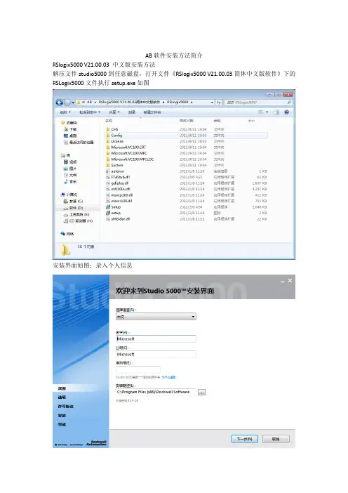
AB软件安装方法简介RSlogix5000 V21.00.03 中文版安装方法解压文件studio5000到任意磁盘,打开文件《RSlogix5000 V21.00.03简体中文版软件》下的RSLogix5000文件执行setup.exe如图安装界面如图:录入个人信息选择需要的组件,默认安装即可。
软件安全许可协议,选择同意所有。
安装进行中界面。
中途会提示是否安装相应的驱动组件,一一同意安装。
结束安装后继续安装仿真软件。
RSLogix Emulate 5000安装方法解压文件studio5000到任意磁盘,打开文件RSLogix Emulate 5000 21.00.00 (CPR 9 SR 5.1)》运行autorun文件,会弹出安装对话:如图选择第一项,根据向导进一步安装如图安装此软件会询问你是否同意罗克韦尔的安全协议,此时选择同意,否则安装不能继续,如图录入个人信息:用户名组织产品序列号安装方式:完全向导安装或自定义安装,这里选择完全向导安装,你也选择自定义安装确认安装:单击install安装完成:询问是否生成桌面快捷图标,至此安装结束,根据软件安装包提供的破解文件进行软件破解授权,具体操作步骤详见《studio5000序列号及破解方法》专业版-序列号:2845012678使用说明:破解使用方法:就是安装一个LIC授权,替换2个DLL文件。
studio5000具体过程如下:1、安装LIC授权lic授权文件“rsi.master2017_new.lic”复制到C:\users\public\documents\Rockwell Automation\Activations注:此路径和操作系统安装盘符有关,默认是C盘这个路径2、替换ECC补丁:如果是FTACommon.dll补丁,只需复制到c:\Program Files\Common Files\Rockwell\或c:\Program Files (x86)\Common Files\Rockwell\注意:FTACommon.dll不通用,复制前要先确认一下原来的文件版本。
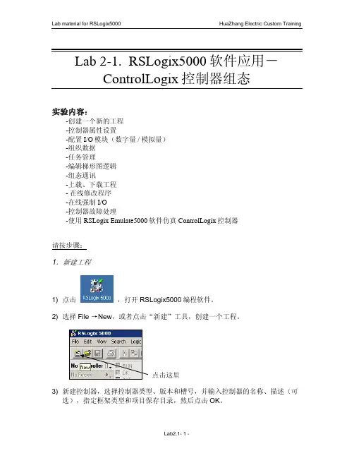
Lab 2-1. RSLogix5000软件应用-ControlLogix控制器组态实验内容:-创建一个新的工程-控制器属性设置-配置I/O模块(数字量 / 模拟量)-组织数据-任务管理-编辑梯形图逻辑-组态通讯-上载、下载工程- 在线修改程序-在线强制I/O-控制器故障处理-使用RSLogix Emulate5000软件仿真ControlLogix控制器请按步骤:1.新建工程1) 点击,打开RSLogix5000编程软件。
2) 选择File →New,或者点击“新建”工具,创建一个工程。
点击这里3) 新建控制器,选择控制器类型、版本和槽号,并输入控制器的名称、描述(可选),指定框架类型和项目保存目录,然后点击OK。
Revision:项目中选用的处理器版本要跟实际处理器的硬件版本相一致(模块的硬件版本可在RSLinx平台中查看)。
Logix 平台提供了固件升级手段。
Type:可选择基于Logix 平台的多种处理器。
Chassis Type:项目中选用的框架类型要跟实际处理器所在的机架相一致。
Slot:确定CPU 所在槽位。
CPU 不受槽位限制,可以插在任意槽中。
4) 树形目录项目管理器控制器文件夹任务文件夹数据类型文件夹I/O组态文件夹2.I/O配置5) 组态本地数字量I/O模块。
右键点击背板图标1756 Backplane,1756-A10,然后选择 New Module。
在模块类型列表中选择1756-OB16D(数字量直流输出模块),单击OK;确定版本信息后在跳出的对话框中设置模块属性,输入模块的名称、描述(可选),选择槽号、通讯格式、电子锁方式等;点击Connection等其余子页面逐步设置RPI时间等内容。
所有组态完成后,点击Finish。
选中IO块,类型应该和框架上的实际模块相符选择OKComm Format:通讯格式决定了I/O模块使用的数据结构,也决定了模块与模块控制器所有权的连接类型,即模块被组态为宿主拥有模式还是只监听模式;输入模块可以有多个宿主,而输出模块只能有一个宿主。
RSLogix Emulator5000快速入门RSLogix Emulator5000是一个软件仿真器,用于Allen BradleyLogix5000控制器系列(ControlLogix®,CompactLogix®,FlexLogix®,SoftLogix5800®and DriveLogix®)。
目的是为了仿真PLC的功能而不需要实际的硬件,并且还可以做进一步的调试。
更多信息可以在AB发布的LGEM5K-GR015A-EN-P中找到。
我们通过一个仿真设置的简单例子,以便更快地介绍。
这个例子主要包括三个步骤。
设置机架监视器。
建立RSLinx连接。
建立一个与仿真硬件相关连的项目。
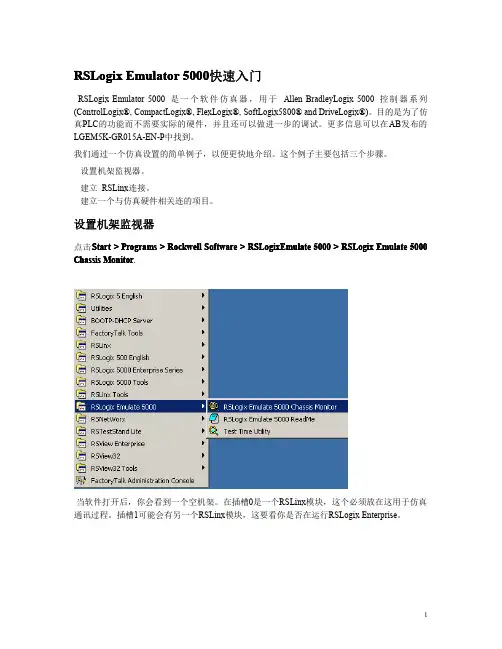
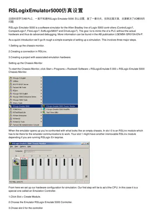
设置机架监视器点击Start>Programs>Rockwell Software>RSLogixEmulate5000>RSLogix Emulate5000 Chassis Monitor.当软件打开后,你会看到一个空机架。
在插槽0是一个RSLinx模块,这个必须放在这用于仿真通讯过程。
插槽1可能会有另一个RSLinx模块,这要看你是否在运行RSLogix Enterprise。
从这里开始,我们设置用于仿真的硬件组态。
第一步,我们要添加CPU。
它被称为仿真控制器。
点击Slot>Create Module.选择Emulator RSLogix Emulate5000Controller.选择插槽2来安放这个控制器。
点击OK把它增加到机架监视器上。
Default lt 在这点上,你可能会有一个原来组态的信息提示。
只管选择Reset the Configuration to Defau Values并点击NEXT。
以下两个对话框显示控制器组态的详细信息。
点击NEXT和FINISH接收隐函操作。
下面我们将增加一些输入/输出仿真。
点击Slot>Create Module.选择1789-SIM32Point Input/Output Simulator.选择插槽3安放并点击OK.接收隐函操作并点击NEXT和FINISH.机架监视器现在有了两个仿真模块准备操作了。

A Quick Tutorial on RSLogix Emulator 5000RSLogix Emulator 5000 is a software simulator for the Allen Bradley line of Logix 5000 controllers (ControlLogix®, CompactLogix®, FlexLogix®, SoftLogix5800® andDriveLogix®. The goal is to mimic the function of a PLC without the actual hardware and thus do advanced debugging. More information can be found in the AB publication LGEM5K-GR015A-EN-P.As a quick introduction we’ll go through a simple example of setting up a simulation. This involves three major steps.1. Setting up the chassis monitor. 建立机架2. Creating a connection in RSLinx. 在 RSlinx 建立连接3. Creating a project with associated emulation hardware. 创建带虚拟控制器的项目 Setting up the Chassis MonitorTo start the Chassis Monitor, click Start > Programs > Rockwell Software > RSLogixEmulate 5000 > RSLogix Emulate 5000 Chassis Monitor.When the emulator opens up you’re confronted with what looks like an empty chassis.In slot 0 is an RSLinx module which has to be there for the emulator communications to work. Your slot 1 might have another irremovable RSLinx module depending if you are running RSLogix Enterprise.From here we set up our hardware configuration for simulation. Our first step will be to add the CPU . In this case it is a special one called an Emulation Controller.1. Click Slot > Create Module.2. Choose the Emulator RSLogix Emulate 5000 Controller.3. Chose slot 2 for the controller4. Click OK to add it to the chassis monitor.5. At this point you may be accosted with a message about previousconfigurations. Just select Reset the Configuration to Default Values and click NEXT .6. The next two dialog screens are for setting up the controller details. Click NEXT and FINISH to accept all the defaults.Next we’ll add some input/output simulation.1. Click Slot > Create Module.2. Choose the 1789-SIM 32 Point Input/Output Simulator.3. Chose slot 3 for the simulator and click OK.4. Accept the defaults for the setup by clicking NEXT and FINISH .The chassis monitor will now have two emulation modules in it ready to go.Creating a connection in RSLinx1. Start RSLinx under Start > Programs > Rockwell Software > RSLinx > RSLinx Classic2. Click Communications > Configure Drivers.3. Select the Virtual Backplane (SoftLogix 58xx driver from the Available Driver Types list.4. Click Add New. The Add New RSLinx Driver dialog box appears. Click OK .5. The new driver appears in the Configured Drivers list. Click Close .Using RSLogix Emulator in a ProjectTo use the emulator in a project you must setup the hardware correctly.1. Start the RSLogix 5000 software and create a new project.2. Under the New Controller window type select an Emulator – RSLogix Emulator 5000 Controller. Give it a name and assign it to the same slot as the one youput in the Chassis Monitor which in our example is slot 2. Click OK.3. In RSLogix 5000's Controller Organizer, right click on the I/O Configuration folder, and then click New Module. The software displays the Select Module window.4. Open the Other folder. Select the 1756-MODULE from the modules list and then click OK.5. The software displays the New Module window. a. Add a Name for the card.b. In the Slot field put the number that corresponds with the Chassis Monitor.c. For the Connection Parameters put in the following and click OK Assembly Instance Input Output Configuration 1 2 16 Size 2 1 0 6. 注意:按上表填,下图中显示的数不准确注意:按上表填,7. 8. On the next Module Properties screen make sure to change the Requested Packet Interval to 50.0 ms.(必须 50ms 以上,否则出错)以上,否则出错)(模块也行,(实际不仿真 I/O 模块也行,只要在 rslinx5000 中建 tag)) Ready, Set,Go You are now ready to use the emulator just like you would any other PLC. Active and set the path to the RSLogix 5000 Emulator. Open WhoThe inputs can be simulated in the emulator’s Chassis Monit or by right clicking on the module and selecting Properties. Under the I/O Data tab is the ability to toggle each of the inputs on or off. Note: RSLogix Emulator is sometimes erroneously called RSEmulator.。
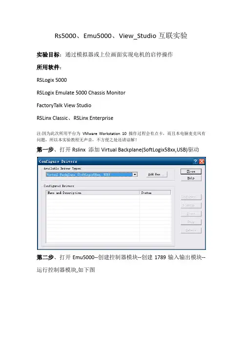
Rs5000、Emu5000、View_Studio互联实验实验目标:通过模拟器或上位画面实现电机的启停操作所用软件:RSLogix 5000RSLogix Emulate 5000 Chassis MonitorFactoryTalk View StudioRSLinx Classic、RSLinx Enterprise注:因为此次所用平台为VMware Workstation 10 操作过程会有点卡,而且本电脑麦克风有问题,所以本实验教程无声音,不方便之处还请谅解!第一步、打开Rslinx 添加Virtual Backplane(SoftLogix58xx,USB)驱动第二步、打开Emu5000--创建控制器模块--创建1789输入输出模块--运行控制器模块,如下图第三步、打开Rs5000--创建新项目--选择控制器模块--然后添加新模块--选择其他--1756模块1756模块的相关参数配置见下图:第四步、编写PLC程序:输入输出模块在3槽,即PLC程序输入点地址Locol:3:I.Data[1].0对应模拟器的inputs 位00,PLC程序输出点地址Locol:3:O.Data[0].对应模拟器的Outputs 位00注意:一个是Data[1],一个是Data[0],不要混淆见下图然后添加程序段--编辑好变量标签--选择网络下载到控制器中并保存、运行控制器。
第五步、打开View_Studio--新建项目-- RSLinx Enterprise链接设置选择创建一个新组态--添加快捷方式--在1789-A17处鼠标右键选开始浏览,直到扫描出配置好的控制器模块和输入输出模块(也可以手动添加控制器模块和输入输出模块)。
然后点击从“设计”复制到“运行时”—点击浏览脱机标签文件—选择已编辑好的程序—验证无问题后,确定再确定。
(脱机文件是用来OFF line标签变量的)第六步、打开图形显示的main画面,画启动、停止按钮、运行状态等图形,设置相关参数,连接变量标签,如下图所示—刷新全部文件夹然后连接相应的标签变量。
RSLogixEmulator5000仿真设置这段时间学习AB PLC,⼀直不知道RSLogix Emulator 5000 怎么设置,废了⼀番功夫,找到这篇⽂章,总算解决了I/O模块的问题RSLogix Emulator 5000 is a software simulator for the Allen Bradley line of Logix 5000 contr ollers (ControlLogix?, CompactLogix?, FlexLogix?, SoftLogix5800? and DriveLogix?). The goa l is to mimic the of a PLC without the actual hardware and thus do advanced debugging. More information can be found in the AB publication LGEM5K-GR015A-EN-P. As a quick introduction we’ll go th rough a simple example of setting up a simulation. This involves three major steps.1.Setting up the chassis monitor.2.Creating a connection in RSLinx.3.Creating a project with associated emulation hardware.Setting up the Chassis MonitorTo start the Chassis Monitor, click Start > Programs > Rockwell Software > RSLogixEmulate 5 000 > RSLogix Emulate 5000 Chassis Monitor.When the emulator opens up you’re confronted with what looks like an empty chassis. In slo t 0 is an RSLinx module which has to be there for the emulator communications to work. Your slot 1 might have another irremovable RSLinx module depending if you are running RSLogix En terprise.From here we set up our hardware configuration for simulation. Our first step will be to ad d the CPU. In this case it is a special one called an Emulation Controller.1.Click Slot > Create Module.2.Choose the Emulator RSLogix Emulate 5000 Controller.3.Chose slot 2 for the controller4.Click OK to add it to the chassis monitor.5.At this point you may be accosted with a message about previous configurations. Jus t select Reset the Configuration to Default s and click NEXT.6.The next two dialog screens are for setting up the controller details. Click NEXT a nd FINISH to accept all the defaults.Next we’ll add some input/output simulation.1.Click Slot > Create Module.2.Choose the 1789-SIM 32 Point Input/Output Simulator.3.Chose slot 3 for the simulator and click OK.4.Accept the defaults for the setup by clicking NEXT and FINISH.The chassis monitor will now have two emulation modules in it ready to go.Creating a connection in RSLinx1.Start RSLinx under Start > Programs > Rockwell Software > RSLinx > RSLinx Classic2.Click Communications > Configure Drivers.3.Select the Virtual Backplane (SoftLogix 58xx) driver from the Available Driver Types list.4.Click Add New. The Add New RSLinx Driver dialog box appears. Click OK.5.The new driver appears in the Configured Drivers list. Click Close.Using RSLogix Emulator in a ProjectTo use the emulator in a project you must setup the hardware correctly.1.Start the RSLogix 5000 software and create a new project.2.Under the New Controller window type select an Emulator – RSLogix Emulator 5000 Controller. Give it a name and assign it to the same slot as the one you put in the Ch assis Monitor which in our example is slot 2. Click OK.3.In RSLogix 5000's Controller Organizer, right click on the I/O Configuration folder,and then click New Module. The software displays the Select Module4.Open the Other folder. Select the 1756-MODULE from the modules list and then click OK.5.The software displays the New Modulea. Add a Name for the card.b. In the Slot field put the number that corresponds with the Chassis Monitor.c. For the Connection Parameters put in the following and click OK6.7.8.On the next Module Properties screen make sure to change the Requested Packet Inter val to 50.0 ms.Ready, Set, GoYou are now ready to use the emulator just like you would any other PLC. Open Who Active a nd set the path to the RSLogix 5000 Emulator.The inputs can be simulated in the emulator’s Chassis Monitor by right clicking on the modu le and selecting Properties. Under the I/O Data tab is the ability to toggle each of the in puts on or off.。
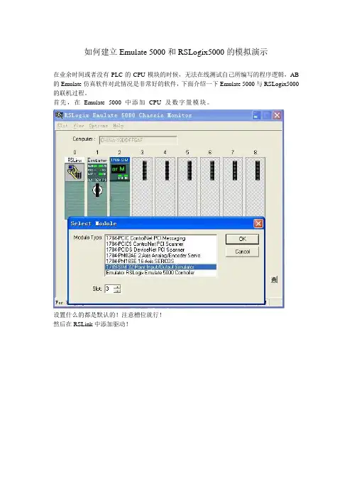
如何建立Emulate 5000和RSLogix5000的模拟演示
在业余时间或者没有PLC的CPU模块的时候,无法在线测试自己所编写的程序逻辑,AB 的Emulate仿真软件对此情况是非常好的软件,下面介绍一下Emulate 5000与RSLogix5000的联机过程。
首先,在Emulate 5000中添加CPU及数字量模块。
设置什么的都是默认的!注意槽位就行!
然后在RSLink中添加驱动!
基本上就可以搜索到CUP及数字量模块了!
然后在RSLogix5000中配置模块!
CPU在创建新程序时选择,一般没问题,主要是数字量模块的通讯!选择模块型号!
注意红色选项中的数据,按这个来没问题!还有后面的程序,是个例子!
1 2
2 1
16 0
时间改为50MS
然后在运行状态下就可以试验了!
可以看到,在例程的运行下,可以控制输入,并输出!。
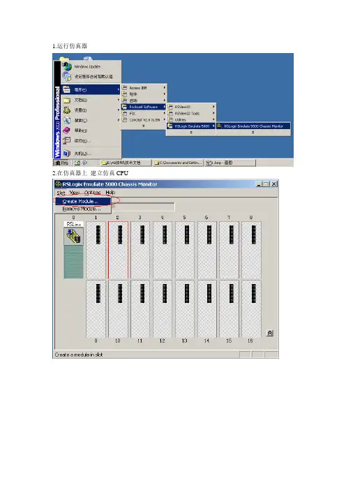
1.运行仿真器
2.在仿真器上建立仿真CPU
3.选择仿真器,选择槽位点击OK
4.默认选项点击下一步
5. 默认选项点击完成
6.仿真器建立完成
7.打开5000工程,点击Offline 选择控制器属性(Controller Properties)
8.选择控制器类型点击Change Controller…
9.选择Emulator 仿真CPU
10.选择版本完成点击OK
11.点击网络路径选择仿真器所在位置点击设置工程路径(Set Project Path)
12.点击在线(Go Online)
13.点击下载(Download)
14.确认下载点击下载(Download)
15.弹出等待窗口工程正在下载中…
16.将仿真器切换到运行模式点击远程模式(Rem Prog) 运行模式(Run Mode)
17.弹出确认窗口点击是运行
18.CPU为运行模式如图绿灯亮
19.打开View32工程在编辑模式下双击系统中的节点
20.选择数据源为OPC服务器选择节点名,服务器,类型最后点击启用接受退出完成
21.选择节点名服务器为内部进程(RSLinx OPC Server)
22.打开需要监视的画面点击运行查看是否与仿真器连上
23.连接正常如图所示。
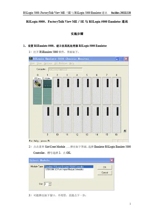
RSLogix 5000、FactoryTalk View ME/SE与RSLogix 5000 Emulator通讯实施步骤1、设置RSEmulate 5000,建立仿真机处理器RSLogix 5000 Emulator1)打开RSEmulate 5000软件,界面如下;2)点击菜单Slot\Creat Module …,弹出如下界面,选择Emulator RSLogix Emulate 5000 Controller,槽号选择2,点OK;3)可能弹出如下窗口,不用管,直接点下一步;4)弹出如下界面,选择RSLogix 5000软件版本,其他默认,点下一步;5)弹出如下界面,点完成;6)完成RSEmulate 5000设置,可看到槽2位置的RSLogix 5000 Emulator处理器。
2、设置RSLinx1)打开RSLinx软件,界面如下;2)点击工具栏图标,弹出如下界面;3)点击下拉列表,选择虚拟背板驱动,点击Add New …;4)弹出如下界面,给OPC服务器取名,点击OK;5)弹出如下界面,槽号选0,点击OK;6) 完成RSLinx 设置,点击Close 关闭界面;7) 点击工具栏图标,可在弹出界面内找到RSLogix 5000 Emulator 处理器。
3、 设置RSLogix 5000,实现RSLogix 5000与仿真机处理器RSLogix 5000 Emulator 通讯通讯、、PLC 程序程序下载及下载及下载及在线监控在线监控1)打开RSLogix 5000软件,界面如下;2)点击菜单File\New …,弹出如下界面,处理器选型如下,版本19,槽号选为2,点击OK;3)建一个简单程序;4)点击图标,弹出窗口,找到如下RSLogix 5000 Emulator,点击Set Project Path,然后点击Go Online;5)弹出如下窗口,点击Download;6)弹出如下窗口,点击Download;7)显示如下界面,开始下载程序到仿真器;8)完成后,在如下界面,选择模式为Run Mode;9)弹出如下界面,点击是;10)完成RSLoigx 5000设置;11)下图为程序在线监控。
AB软件安装纪要
1.Logix5000 20.01安装
打开“RSLogix5000-20.01.00-Lite英文版”文件夹,进行安装,安装完成后进行破解;
打开“RSLogix 5000 2.0授权”文件夹,进行文件替换破解
如果想用1769PLC,则还需要安装一个AOP文件,打开AOP文件夹进行安装
如需将此版本更换成中文版,则打开RSLogix5000 V20.01 文件夹重新安装一遍,则可完成,不过目前为止还没有试过
2.Rslogix Emulate5000 v20安装
打开“仿真软件Emulate5000版本20”文件夹进行安装
安装完成后打开“包含Rslogix Emulate5000 v20授权”文件夹进行授权
授权分两大步,第二步有两个环节,2.2和2.7
3.SE6.0-ZHE安装
打开”SE6.0-ZHE”文件夹进行安装,打开安装盘后,需要安装3和5选项,安装完成后,打开软件
在左上角的项目名称鼠标右键,添加RSlinx Enterprise 可建立连接
打开“AB授权及工具包”进行授权,参照授权方法,授权完成后即可达到运行效果4.三个软件建议按照如下安装顺序:
Logix5000—仿真—SE。
打开SE安装界面后只安装3和5,不然Logix5000中的RSlinx无法使用,因为SE中的RSlinx为低版本,安装后即出错了。
RSLogix 5000、FactoryTalk View ME/SE与RSLogix 5000 Emulator通讯实施步骤1、设置RSEmulate 5000,建立仿真机处理器RSLogix 5000 Emulator1)打开RSEmulate 5000软件,界面如下;2)点击菜单Slot\Creat Module …,弹出如下界面,选择Emulator RSLogix Emulate 5000 Controller,槽号选择2,点OK;3)可能弹出如下窗口,不用管,直接点下一步;4)弹出如下界面,选择RSLogix 5000软件版本,其他默认,点下一步;5)弹出如下界面,点完成;6)完成RSEmulate 5000设置,可看到槽2位置的RSLogix 5000 Emulator处理器。
2、设置RSLinx1)打开RSLinx软件,界面如下;2)点击工具栏图标,弹出如下界面;3)点击下拉列表,选择虚拟背板驱动,点击Add New …;4)弹出如下界面,给OPC服务器取名,点击OK;5)弹出如下界面,槽号选0,点击OK;6) 完成RSLinx 设置,点击Close 关闭界面;7) 点击工具栏图标,可在弹出界面内找到RSLogix 5000 Emulator 处理器。
3、 设置RSLogix 5000,实现RSLogix 5000与仿真机处理器RSLogix 5000 Emulator 通讯通讯、、PLC 程序程序下载及下载及下载及在线监控在线监控1)打开RSLogix 5000软件,界面如下;2)点击菜单File\New …,弹出如下界面,处理器选型如下,版本19,槽号选为2,点击OK;3)建一个简单程序;4)点击图标,弹出窗口,找到如下RSLogix 5000 Emulator,点击Set Project Path,然后点击Go Online;5)弹出如下窗口,点击Download;6)弹出如下窗口,点击Download;7)显示如下界面,开始下载程序到仿真器;8)完成后,在如下界面,选择模式为Run Mode;9)弹出如下界面,点击是;10)完成RSLoigx 5000设置;11)下图为程序在线监控。
RSLogix5000仿真快速讲解RSLogix Emulator 5000是一个软件模拟5000 Logix控制器的软件。
其目的是在没有硬件的情况下,模拟的真实功能PLC,. 并进行调试。
更多的信息可以参考LGEM5K-GR015A-EN-P AB出版。
As a quick introduction we’ll go through a simple example of setting up a simulation. 作为一个快速的介绍,我们通过过一个简单的例子建立的仿真。
三个主要步骤。
1.建立一个主机监控。
2.RSLinx.创建一个连接RSLinx。
3.构建一个项目相关的仿真硬件。
建立一个主机架点击开始> > > > RSLogixEmulate RSLogix5000 Chassis Monitor。
当仿真打开,只有一个空的机架。
一个RSLinx模块已经在0槽内。
在slot 1 可以根据模拟项目的需要来加入另一个RSLinx 模块来进入通讯扩展。
在这里我们搭建项目相关的硬件配置。
第一步将会增加CPU模块。
这是一个叫做Emulation Controller模块。
点击槽>创建模块。
1.选择模拟器RSLogix模仿5000控制器。
2.槽号选择23.点击加入4.在这一点上,你可能会出现一个讯息配置对话框。
配置默认值并单击“下一步”。
5.接下来的两个对话框设置,是控制器的细节。
点击“下一步”并完成对接受所有的默认值。
接下来我们将加入一些输入/输出的模块。
1.点击槽>创建模块。
2.选择1789 -SIM 32点输入/输出模拟器。
3.槽号选择3,然后点击OK。
4.A.接受缺省设置,点击下结束。
机架上将现在有两个仿真模块。
RSLinxRSLinx创建一个连接1.开始>程序下RSLinx > > >罗克韦尔软件RSLinx专业版2.点击Communications >配置Configure Drivers.3.选择the Virtual Backplane (SoftLogix 58xx) driver现有的驱动类型列表。
编号:AL032_17044_桑河二级_170909 关键词:桑河、AB 变频器报告日期:2017-09-09类似案例问题现象描述桑河二级项目渗漏排水、检修排水、中低压空压机等采用RockWell公司AB PLC,PLC编程软件RSLogic5000。
渗漏排水、检修排水控制对象类似,分别控制三台水泵启停,用于集水井排水。
三台泵其中两台为主用泵,一台为备用泵,三台泵需要进行轮换,实现水泵科学运行。
渗漏排水LCU上电后发现出所备份程序中关于泵轮换部分有问题,上电后从触摸屏上可以观察到主泵2泵号等于3,而主泵1与备用泵本号由1-2/2-1不停地切换。
检修排水所在楼层低,当地环境温度接近40℃,同时厂房内土建工作还没有结束,粉尘、噪声极大。
加之现场PLC仅由临时电源供电,非常不利于调试和分析,于是考虑通过安装仿真软件的方法,在办公室进行测试和调试。
网上了解到AB PLC官方提供了仿真软件:RSLogic Emulate。
原因分析处理方案及结果准备内容:1.RSLogic Emulate 5000仿真软件(版本V20.01);2.flexsvr.exe授权软件;3.ftasystem.lic授权文件库;4.RSLogic 5000 PLC软件(不再详细描述);5.RSLinx Classic管理软件(不再详细描述);编号:AL032_17044_桑河二级_170909 关键词:桑河、AB 变频器报告日期:2017-09-09 安装步骤:1.确保已正确安装RSLinx Classic及RSLogic 5000软件;2.安装RSLogic Emulate 5000仿真软件,确保仿真软件版本与已安装的PLC版本一致,如下图所示。
然后直接运行setup.exe执行安装;(建议将360安全卫士退出)3.替换授权文件,替换前先备份原来的文件:将ftasystem.lic放到覆盖同名文件:C:\Documents and Settings\All Users\Documents\RockwellAutomation\Activations4.替换授权软件,替换前先备份原来的文件:将flexsvr.exe放到以下目录,覆盖同名文件(建议备份一下原文件):C:\Program Files\RockwellSoftware\FactoryTalk Activation 。
仿真软件的应用软件安装:实验1:建立仿真系统,模拟计数器的运行双击仿真软件图标:上图表示一个17槽机架。
在3号槽添加处理器:右击3#槽,选择create,在对话框中选择emulator rslogix emulate5000 control 处理器按OK下图显示:处理器16版,内存3M,按下一步。
按完成打开左上角的RSLinx,点击communictions\configure drive从available drive下拉菜单中选择virtual backplane driver,点击ADD newOK选择close.确认在RSWho窗口,可以看到3#槽的CPU.打开RSLogix5000,新建工程,名称:“PZW”,注意选择的CPU型号,槽号,版本号和虚拟机架上的保持一致.OK. 编程:创建一个计数器下载,运行,这时计数器进入循环计数状态本实验结束。
实验2:两个处理器之间的通信在仿真机架4号槽再添加一个CPU在controll tags中新增生产者标签,名称为”produced_tag”按“监控tags”,将值变为77存盘,下载为4槽处理器再创建一个程序,工程名称:PP确认后I/O配置如下:在数据库中建立一个tag,名称为“consumed_tag”,类型DINT 在I/O配置右击,添加新模块新CPU名称随意,取为“ZW”,3号槽下图显示在3号槽添加了新模块在数据库右击”consumed_tag”,选择:编辑consumedtag属性,将类型改为“消费”,在连接页:设置生产者名称和远程数据(即要读取的数据)这时数据库变为:编程(这是随便编制的)保存,下载,运行程序可以看到消费者的值是77,说明通信成功。
为了进一步验证,生产者改为200消费者也变为200。
本实验结束。
实验3:集成运动控制将工程PZW离线I/O配置添加新模块OK点击新建axis,名称“x_axis”确定后,将轴分配给0通道确认后I/O配置为:在数据库中新建运动组,名称“group1”右击gruup1,选择“group1向导”将轴移到右边的窗口按“完成”保存,下载。
仿真软件的应用
软件安装:
实验1:建立仿真系统,模拟计数器的运行
双击仿真软件图标:
上图表示一个17槽机架。
在3号槽添加处理器:右击3#槽,选择create,在对话框中选择emulator rslogix emulate5000 control 处理器
按OK
下图显示:处理器16版,内存3M,
按下一步。
按完成
打开左上角的RSLinx,点击communictions\configure drive
从available drive下拉菜单中选择virtual backplane driver,点击ADD new
OK
选择close.确认在RSWho窗口,可以看到3#槽的CPU.
打开RSLogix5000,新建工程,名称:“PZW”,注意选择的CPU型号,槽号,版本号和虚拟机架上的保持一致.
OK. 编程:创建一个计数器
下载,运行,这时计数器进入循环计数状态
本实验结束。
实验2:两个处理器之间的通信
在仿真机架4号槽再添加一个CPU
在controll tags中新增生产者标签,名称为”produced_tag”
按“监控tags”,将值变为77
存盘,下载
为4槽处理器再创建一个程序,工程名称:PP
确认后I/O配置如下:
在数据库中建立一个tag,名称为“consumed_tag”,类型DINT 在I/O配置右击,添加新模块
新CPU名称随意,取为“ZW”,3号槽
下图显示在3号槽添加了新模块
在数据库右击”consumed_tag”,选择:编辑consumedtag属性,将类型改为“消费”,在连接页:设置生产者名称和远程数据(即要读取的数据)
这时数据库变为:
编程(这是随便编制的)
保存,下载,运行程序
可以看到消费者的值是77,说明通信成功。
为了进一步验证,生产者改为200
消费者也变为200。
本实验结束。
实验3:集成运动控制
将工程PZW离线
I/O配置添加新模块
OK
点击新建axis,名称“x_axis”
确定后,将轴分配给0通道
确认后I/O配置为:
在数据库中新建运动组,名称“group1”
右击gruup1,选择“group1向导”
将轴移到右边的窗口
按“完成”
保存,下载。
本实验结束。